EP4375106A1 - Engin agricole autonome équipé d'un système de motorisation éclaté - Google Patents
Engin agricole autonome équipé d'un système de motorisation éclaté Download PDFInfo
- Publication number
- EP4375106A1 EP4375106A1 EP23203428.0A EP23203428A EP4375106A1 EP 4375106 A1 EP4375106 A1 EP 4375106A1 EP 23203428 A EP23203428 A EP 23203428A EP 4375106 A1 EP4375106 A1 EP 4375106A1
- Authority
- EP
- European Patent Office
- Prior art keywords
- autonomous agricultural
- air
- agricultural machine
- air circulation
- machine
- Prior art date
- Legal status (The legal status is an assumption and is not a legal conclusion. Google has not performed a legal analysis and makes no representation as to the accuracy of the status listed.)
- Granted
Links
Images

Classifications
-
- F—MECHANICAL ENGINEERING; LIGHTING; HEATING; WEAPONS; BLASTING
- F02—COMBUSTION ENGINES; HOT-GAS OR COMBUSTION-PRODUCT ENGINE PLANTS
- F02M—SUPPLYING COMBUSTION ENGINES IN GENERAL WITH COMBUSTIBLE MIXTURES OR CONSTITUENTS THEREOF
- F02M35/00—Combustion-air cleaners, air intakes, intake silencers, or induction systems specially adapted for, or arranged on, internal-combustion engines
- F02M35/10—Air intakes; Induction systems
- F02M35/10242—Devices or means connected to or integrated into air intakes; Air intakes combined with other engine or vehicle parts
- F02M35/10262—Flow guides, obstructions, deflectors or the like
-
- B—PERFORMING OPERATIONS; TRANSPORTING
- B60—VEHICLES IN GENERAL
- B60K—ARRANGEMENT OR MOUNTING OF PROPULSION UNITS OR OF TRANSMISSIONS IN VEHICLES; ARRANGEMENT OR MOUNTING OF PLURAL DIVERSE PRIME-MOVERS IN VEHICLES; AUXILIARY DRIVES FOR VEHICLES; INSTRUMENTATION OR DASHBOARDS FOR VEHICLES; ARRANGEMENTS IN CONNECTION WITH COOLING, AIR INTAKE, GAS EXHAUST OR FUEL SUPPLY OF PROPULSION UNITS IN VEHICLES
- B60K11/00—Arrangement in connection with cooling of propulsion units
- B60K11/08—Air inlets for cooling; Shutters or blinds therefor
-
- A—HUMAN NECESSITIES
- A01—AGRICULTURE; FORESTRY; ANIMAL HUSBANDRY; HUNTING; TRAPPING; FISHING
- A01C—PLANTING; SOWING; FERTILISING
- A01C23/00—Distributing devices specially adapted for liquid manure or other fertilising liquid, including ammonia, e.g. transport tanks or sprinkling wagons
- A01C23/04—Distributing under pressure; Distributing mud; Adaptation of watering systems for fertilising-liquids
- A01C23/047—Spraying of liquid fertilisers
-
- A—HUMAN NECESSITIES
- A01—AGRICULTURE; FORESTRY; ANIMAL HUSBANDRY; HUNTING; TRAPPING; FISHING
- A01M—CATCHING, TRAPPING OR SCARING OF ANIMALS; APPARATUS FOR THE DESTRUCTION OF NOXIOUS ANIMALS OR NOXIOUS PLANTS
- A01M7/00—Special adaptations or arrangements of liquid-spraying apparatus for purposes covered by this subclass
- A01M7/0025—Mechanical sprayers
- A01M7/0032—Pressure sprayers
- A01M7/0042—Field sprayers, e.g. self-propelled, drawn or tractor-mounted
-
- B—PERFORMING OPERATIONS; TRANSPORTING
- B60—VEHICLES IN GENERAL
- B60K—ARRANGEMENT OR MOUNTING OF PROPULSION UNITS OR OF TRANSMISSIONS IN VEHICLES; ARRANGEMENT OR MOUNTING OF PLURAL DIVERSE PRIME-MOVERS IN VEHICLES; AUXILIARY DRIVES FOR VEHICLES; INSTRUMENTATION OR DASHBOARDS FOR VEHICLES; ARRANGEMENTS IN CONNECTION WITH COOLING, AIR INTAKE, GAS EXHAUST OR FUEL SUPPLY OF PROPULSION UNITS IN VEHICLES
- B60K13/00—Arrangement in connection with combustion air intake or gas exhaust of propulsion units
- B60K13/02—Arrangement in connection with combustion air intake or gas exhaust of propulsion units concerning intake
-
- F—MECHANICAL ENGINEERING; LIGHTING; HEATING; WEAPONS; BLASTING
- F01—MACHINES OR ENGINES IN GENERAL; ENGINE PLANTS IN GENERAL; STEAM ENGINES
- F01P—COOLING OF MACHINES OR ENGINES IN GENERAL; COOLING OF INTERNAL-COMBUSTION ENGINES
- F01P1/00—Air cooling
- F01P1/06—Arrangements for cooling other engine or machine parts
-
- F—MECHANICAL ENGINEERING; LIGHTING; HEATING; WEAPONS; BLASTING
- F01—MACHINES OR ENGINES IN GENERAL; ENGINE PLANTS IN GENERAL; STEAM ENGINES
- F01P—COOLING OF MACHINES OR ENGINES IN GENERAL; COOLING OF INTERNAL-COMBUSTION ENGINES
- F01P5/00—Pumping cooling-air or liquid coolants
- F01P5/02—Pumping cooling-air; Arrangements of cooling-air pumps, e.g. fans or blowers
-
- F—MECHANICAL ENGINEERING; LIGHTING; HEATING; WEAPONS; BLASTING
- F01—MACHINES OR ENGINES IN GENERAL; ENGINE PLANTS IN GENERAL; STEAM ENGINES
- F01P—COOLING OF MACHINES OR ENGINES IN GENERAL; COOLING OF INTERNAL-COMBUSTION ENGINES
- F01P5/00—Pumping cooling-air or liquid coolants
- F01P5/02—Pumping cooling-air; Arrangements of cooling-air pumps, e.g. fans or blowers
- F01P5/06—Guiding or ducting air to, or from, ducted fans
-
- F—MECHANICAL ENGINEERING; LIGHTING; HEATING; WEAPONS; BLASTING
- F02—COMBUSTION ENGINES; HOT-GAS OR COMBUSTION-PRODUCT ENGINE PLANTS
- F02B—INTERNAL-COMBUSTION PISTON ENGINES; COMBUSTION ENGINES IN GENERAL
- F02B29/00—Engines characterised by provision for charging or scavenging not provided for in groups F02B25/00, F02B27/00 or F02B33/00 - F02B39/00; Details thereof
- F02B29/04—Cooling of air intake supply
- F02B29/0406—Layout of the intake air cooling or coolant circuit
- F02B29/0425—Air cooled heat exchangers
- F02B29/0431—Details or means to guide the ambient air to the heat exchanger, e.g. having a fan, flaps, a bypass or a special location in the engine compartment
-
- F—MECHANICAL ENGINEERING; LIGHTING; HEATING; WEAPONS; BLASTING
- F02—COMBUSTION ENGINES; HOT-GAS OR COMBUSTION-PRODUCT ENGINE PLANTS
- F02M—SUPPLYING COMBUSTION ENGINES IN GENERAL WITH COMBUSTIBLE MIXTURES OR CONSTITUENTS THEREOF
- F02M35/00—Combustion-air cleaners, air intakes, intake silencers, or induction systems specially adapted for, or arranged on, internal-combustion engines
- F02M35/02—Air cleaners
- F02M35/04—Air cleaners specially arranged with respect to engine, to intake system or specially adapted to vehicle; Mounting thereon ; Combinations with other devices
-
- F—MECHANICAL ENGINEERING; LIGHTING; HEATING; WEAPONS; BLASTING
- F02—COMBUSTION ENGINES; HOT-GAS OR COMBUSTION-PRODUCT ENGINE PLANTS
- F02M—SUPPLYING COMBUSTION ENGINES IN GENERAL WITH COMBUSTIBLE MIXTURES OR CONSTITUENTS THEREOF
- F02M35/00—Combustion-air cleaners, air intakes, intake silencers, or induction systems specially adapted for, or arranged on, internal-combustion engines
- F02M35/10—Air intakes; Induction systems
- F02M35/10006—Air intakes; Induction systems characterised by the position of elements of the air intake system in direction of the air intake flow, i.e. between ambient air inlet and supply to the combustion chamber
- F02M35/10013—Means upstream of the air filter; Connection to the ambient air
-
- F—MECHANICAL ENGINEERING; LIGHTING; HEATING; WEAPONS; BLASTING
- F02—COMBUSTION ENGINES; HOT-GAS OR COMBUSTION-PRODUCT ENGINE PLANTS
- F02M—SUPPLYING COMBUSTION ENGINES IN GENERAL WITH COMBUSTIBLE MIXTURES OR CONSTITUENTS THEREOF
- F02M35/00—Combustion-air cleaners, air intakes, intake silencers, or induction systems specially adapted for, or arranged on, internal-combustion engines
- F02M35/10—Air intakes; Induction systems
- F02M35/10242—Devices or means connected to or integrated into air intakes; Air intakes combined with other engine or vehicle parts
- F02M35/10268—Heating, cooling or thermal insulating means
-
- F—MECHANICAL ENGINEERING; LIGHTING; HEATING; WEAPONS; BLASTING
- F02—COMBUSTION ENGINES; HOT-GAS OR COMBUSTION-PRODUCT ENGINE PLANTS
- F02M—SUPPLYING COMBUSTION ENGINES IN GENERAL WITH COMBUSTIBLE MIXTURES OR CONSTITUENTS THEREOF
- F02M35/00—Combustion-air cleaners, air intakes, intake silencers, or induction systems specially adapted for, or arranged on, internal-combustion engines
- F02M35/16—Combustion-air cleaners, air intakes, intake silencers, or induction systems specially adapted for, or arranged on, internal-combustion engines characterised by use in vehicles
- F02M35/161—Arrangement of the air intake system in the engine compartment, e.g. with respect to the bonnet or the vehicle front face
-
- F—MECHANICAL ENGINEERING; LIGHTING; HEATING; WEAPONS; BLASTING
- F02—COMBUSTION ENGINES; HOT-GAS OR COMBUSTION-PRODUCT ENGINE PLANTS
- F02M—SUPPLYING COMBUSTION ENGINES IN GENERAL WITH COMBUSTIBLE MIXTURES OR CONSTITUENTS THEREOF
- F02M35/00—Combustion-air cleaners, air intakes, intake silencers, or induction systems specially adapted for, or arranged on, internal-combustion engines
- F02M35/16—Combustion-air cleaners, air intakes, intake silencers, or induction systems specially adapted for, or arranged on, internal-combustion engines characterised by use in vehicles
- F02M35/164—Heavy duty vehicles, e.g. trucks, trains, agricultural or construction machines
-
- A—HUMAN NECESSITIES
- A01—AGRICULTURE; FORESTRY; ANIMAL HUSBANDRY; HUNTING; TRAPPING; FISHING
- A01M—CATCHING, TRAPPING OR SCARING OF ANIMALS; APPARATUS FOR THE DESTRUCTION OF NOXIOUS ANIMALS OR NOXIOUS PLANTS
- A01M7/00—Special adaptations or arrangements of liquid-spraying apparatus for purposes covered by this subclass
- A01M7/0003—Atomisers or mist blowers
- A01M7/0014—Field atomisers, e.g. orchard atomisers, self-propelled, drawn or tractor-mounted
-
- A—HUMAN NECESSITIES
- A01—AGRICULTURE; FORESTRY; ANIMAL HUSBANDRY; HUNTING; TRAPPING; FISHING
- A01M—CATCHING, TRAPPING OR SCARING OF ANIMALS; APPARATUS FOR THE DESTRUCTION OF NOXIOUS ANIMALS OR NOXIOUS PLANTS
- A01M7/00—Special adaptations or arrangements of liquid-spraying apparatus for purposes covered by this subclass
- A01M7/0082—Undercarriages, frames, mountings, couplings, tanks
-
- B—PERFORMING OPERATIONS; TRANSPORTING
- B60—VEHICLES IN GENERAL
- B60K—ARRANGEMENT OR MOUNTING OF PROPULSION UNITS OR OF TRANSMISSIONS IN VEHICLES; ARRANGEMENT OR MOUNTING OF PLURAL DIVERSE PRIME-MOVERS IN VEHICLES; AUXILIARY DRIVES FOR VEHICLES; INSTRUMENTATION OR DASHBOARDS FOR VEHICLES; ARRANGEMENTS IN CONNECTION WITH COOLING, AIR INTAKE, GAS EXHAUST OR FUEL SUPPLY OF PROPULSION UNITS IN VEHICLES
- B60K11/00—Arrangement in connection with cooling of propulsion units
- B60K11/02—Arrangement in connection with cooling of propulsion units with liquid cooling
- B60K11/04—Arrangement or mounting of radiators, radiator shutters, or radiator blinds
-
- B—PERFORMING OPERATIONS; TRANSPORTING
- B60—VEHICLES IN GENERAL
- B60K—ARRANGEMENT OR MOUNTING OF PROPULSION UNITS OR OF TRANSMISSIONS IN VEHICLES; ARRANGEMENT OR MOUNTING OF PLURAL DIVERSE PRIME-MOVERS IN VEHICLES; AUXILIARY DRIVES FOR VEHICLES; INSTRUMENTATION OR DASHBOARDS FOR VEHICLES; ARRANGEMENTS IN CONNECTION WITH COOLING, AIR INTAKE, GAS EXHAUST OR FUEL SUPPLY OF PROPULSION UNITS IN VEHICLES
- B60K11/00—Arrangement in connection with cooling of propulsion units
- B60K11/06—Arrangement in connection with cooling of propulsion units with air cooling
-
- B—PERFORMING OPERATIONS; TRANSPORTING
- B60—VEHICLES IN GENERAL
- B60K—ARRANGEMENT OR MOUNTING OF PROPULSION UNITS OR OF TRANSMISSIONS IN VEHICLES; ARRANGEMENT OR MOUNTING OF PLURAL DIVERSE PRIME-MOVERS IN VEHICLES; AUXILIARY DRIVES FOR VEHICLES; INSTRUMENTATION OR DASHBOARDS FOR VEHICLES; ARRANGEMENTS IN CONNECTION WITH COOLING, AIR INTAKE, GAS EXHAUST OR FUEL SUPPLY OF PROPULSION UNITS IN VEHICLES
- B60K17/00—Arrangement or mounting of transmissions in vehicles
- B60K17/04—Arrangement or mounting of transmissions in vehicles characterised by arrangement, location or kind of gearing
- B60K17/10—Arrangement or mounting of transmissions in vehicles characterised by arrangement, location or kind of gearing of fluid gearing
-
- B—PERFORMING OPERATIONS; TRANSPORTING
- B60—VEHICLES IN GENERAL
- B60Y—INDEXING SCHEME RELATING TO ASPECTS CROSS-CUTTING VEHICLE TECHNOLOGY
- B60Y2200/00—Type of vehicle
- B60Y2200/20—Off-Road Vehicles
- B60Y2200/22—Agricultural vehicles
-
- B—PERFORMING OPERATIONS; TRANSPORTING
- B62—LAND VEHICLES FOR TRAVELLING OTHERWISE THAN ON RAILS
- B62D—MOTOR VEHICLES; TRAILERS
- B62D49/00—Tractors
- B62D49/06—Tractors adapted for multi-purpose use
- B62D49/0607—Straddle tractors, used for instance above vine stocks, rows of bushes, or the like
-
- F—MECHANICAL ENGINEERING; LIGHTING; HEATING; WEAPONS; BLASTING
- F02—COMBUSTION ENGINES; HOT-GAS OR COMBUSTION-PRODUCT ENGINE PLANTS
- F02B—INTERNAL-COMBUSTION PISTON ENGINES; COMBUSTION ENGINES IN GENERAL
- F02B29/00—Engines characterised by provision for charging or scavenging not provided for in groups F02B25/00, F02B27/00 or F02B33/00 - F02B39/00; Details thereof
- F02B29/04—Cooling of air intake supply
- F02B29/0406—Layout of the intake air cooling or coolant circuit
- F02B29/0425—Air cooled heat exchangers
-
- F—MECHANICAL ENGINEERING; LIGHTING; HEATING; WEAPONS; BLASTING
- F05—INDEXING SCHEMES RELATING TO ENGINES OR PUMPS IN VARIOUS SUBCLASSES OF CLASSES F01-F04
- F05D—INDEXING SCHEME FOR ASPECTS RELATING TO NON-POSITIVE-DISPLACEMENT MACHINES OR ENGINES, GAS-TURBINES OR JET-PROPULSION PLANTS
- F05D2220/00—Application
- F05D2220/40—Application in turbochargers
Definitions
- the present invention relates to the field of autonomous agricultural machinery.
- the present invention relates to an autonomous agricultural machine, in particular adapted for spraying treatment product on crops, comprising in particular two tanks arranged on each side, between the front wheel and the rear wheel, in the wheelbase of the machine, and aims for such an autonomous agricultural machine equipped with an exploded thermal motorization system.
- the state of the art includes examples of autonomous agricultural machinery, in particular autonomous agricultural spraying machinery whose function is to spray a liquid treatment product on crops.
- autonomous agricultural spraying machinery whose function is to spray a liquid treatment product on crops.
- such a known autonomous agricultural spraying machine can be configured to spray an active product on vines.
- Such autonomous agricultural machines have a frame and four wheels, as well as tools and/or two side tanks, arranged on their sides, between the front wheel and the rear wheel, on each side.
- a general problem in this context concerns a need for more power.
- Known autonomous agricultural machines have electric or thermal gasoline engine systems with a power generally less than 30 HP.
- the present invention proposes an autonomous agricultural machine with a split thermal motor system and a specific cooling system.
- the subject of the invention is an autonomous agricultural machine comprising a frame having an inverted U-shaped section, to which at least one front wheel and at least one rear wheel are connected and defining a track, the frame having two sides, corresponding to the branches of the inverted U and a roof, corresponding to the base of the inverted U;
- the autonomous agricultural machine also includes a thermal power system comprising a motor.
- the autonomous agricultural machine comprises a cooling system having an air circulation gallery arranged in the upper part of the frame, directly under the roof, the air circulation gallery having at least one opening to allow the admission of outside air in the air circulation gallery and a top air outlet to expel warm air upwards, above the roof.
- the cooling system also includes a ventilation device to ensure air circulation in the air circulation gallery.
- the air circulation gallery is configured to allow the circulation of air to cool the engine, in particular to cool a flow of water circulating in the engine and/or a flow of oil circulating in hydraulic circuits of hydraulic systems of autonomous agricultural machinery.
- the air circulation gallery comprises longitudinal and transverse corridors arranged to provide, between these corridors, at least one volume, the autonomous agricultural machine comprising at least one radiator arranged in said volume, so as to dissipate heat into the air circulating in the air circulation gallery.
- the ventilation device comprises at least one fan arranged above the roof.
- the air circulation gallery has a rear opening and two longitudinal openings to allow the admission of outside air into the air circulation gallery.
- the at least one opening of the air circulation gallery can be closed by a mesh configured to let air pass and to block the admission of foreign bodies into the air circulation gallery.
- the motor system also comprises an exhaust device and an air filter, the motor being arranged on one side of the frame, that is to say substantially in alignment with a branch of the U-shaped section of the frame, and the air filter being arranged opposite the engine, that is to say substantially in alignment with an opposite branch of the U-shaped section of the framework, the air filter being connected to the engine by an air circulation channel.
- the autonomous agricultural machine also comprises at least one main advancement pump, a booster pump for the main advancement pump and an accessory pump arranged in a volume located between a tool-carrying zone, located in the track and in the wheelbase of the autonomous agricultural machine, and the roof, the main advancement pump being configured to provide hydraulic energy to hydraulic systems allowing the advancement of the autonomous agricultural machine and the accessory pump being configured to provide hydraulic energy to hydraulic systems allowing the animation of tools mounted on the tool holder.
- the autonomous agricultural machine comprises a turbo and an intercooler, in which the cooling system is also configured to cool an intake air flow at the outlet of the turbo, the air flow of admission at the exit of the turbo being cooled by the air circulating in the air circulation gallery by means of the intercooler.
- the engine is a diesel engine, for example having a power greater than 50 HP.
- the autonomous agricultural machine forms an autonomous agricultural spraying machine comprising two side tanks arranged substantially between the front wheel and the rear wheel, respectively on each side of the autonomous agricultural spraying machine, the agricultural machine autonomous spraying system further comprising a spraying system, the spraying system comprising at least two side recovery panels, the side tanks and the recovery panels being located in the path of the autonomous agricultural spraying machine, corresponding to its width, substantially in the alignment of each side defined by the framework, on each side of the autonomous agricultural spraying machine.
- the invention relates to an autonomous agricultural machine.
- the autonomous agricultural machine is configured to allow the spraying of active product.
- the autonomous agricultural machine includes side tanks containing a treatment product.
- the autonomous agricultural machine is an autonomous four-wheel straddler, allowing in particular, for example, the processing of vines.
- the side tanks are particularly arranged on either side, between the front wheel and the rear wheel, in the impasto of the autonomous agricultural spraying machine.
- the autonomous agricultural machine can, however, be configured to perform other functions using other tools.
- the autonomous agricultural machine can be equipped with a trimmer.
- the present invention applies to an autonomous agricultural machine 1 equipped with recovery panels and treatment product tanks, the autonomous agricultural machine being configured to allow the spraying of a plot of vines.
- This example is, however, illustrative.
- the possibility of integrating recovery panels and side treatment product tanks is advantageous and this possibility constitutes a preferred embodiment.
- the autonomous agricultural machine can be configured to perform other functions.
- the autonomous agricultural machine 1 may not be equipped with recovery panels or product tanks, but be equipped with a tool holder on which a trimmer or any other soil working tool is mounted.
- the autonomous agricultural machine includes a tool holder located in the track and in the wheelbase of the machine, in particular for carrying tools placed on the sides of the machine, inside.
- the tool holder can accommodate trimming type tools for example.
- the tool holder area can also receive side recovery panels, under which side tanks 11, 12 are arranged.
- the autonomous agricultural machine 1 represented on the figures 1 to 3 comprises a frame 2 having an inverted U-shaped section.
- the autonomous agricultural machine 1 here has side tanks 11 and 12 intended to contain a treatment product, in particular a liquid or a mixture, for treating crops, in particular vines.
- the U-shaped section comprises two vertical branches and a horizontal base defining the upper part of the framework 2.
- the framework 2 thus comprises two branches defining the sides of the autonomous agricultural machine 1 and a base defining a roof of the machine .
- the machine here includes four wheels 13, i.e. two front wheels and two rear wheels.
- the front wheels have an axis of rotation and the rear wheels have an axis of rotation, the front axes of rotation and rear defining a wheelbase of the machine.
- the width of the frame 2, corresponding to the distance between the left wheels and the right wheels, defines the track of the autonomous agricultural machine 1.
- the autonomous agricultural machine 1 shown for illustrative purposes on the figures 1 to 3 thus forms an autonomous spray straddle 1
- the autonomous agricultural spraying machine 1 here comprises recovery panels configured to capture any droplet of treatment product passing through the vegetation to be treated. These recovery panels are preferably associated with recovery tanks arranged below and connected to peristaltic pumps to reintroduce the recovered treatment product into the side tanks 11, 12.
- the autonomous agricultural machine 1 also comprises a motor system based on a thermal engine 3, in particular of the diesel type, with its cooling system.
- the motor system comprises an exhaust device connected to the engine 3.
- the engine 3 being of the diesel type
- the exhaust device comprises, at the end of the exhaust pipe 31, a particle filter 32
- the particle filter 32 is adapted to European regulations relating to diesel-type thermal engines.
- the roof of the autonomous agricultural machine 1 is preferably as low as possible in order to guarantee the lowest possible center of gravity and therefore better stability on slopes and slopes.
- the recovery panels must preferably be arranged in the wheelbase and in the track of the machine.
- the motorization system is split: the air filter 33 is on the opposite side to the engine 3. This makes it possible to accommodate the recovery panels in the wheelbase and in the track without increasing the size or height of the machine autonomous agricultural 1.
- the engine 3 is cooled by a cooling system.
- the cooling system is configured to cool the engine 3 of the motorization system, in particular the water circulating in the engine 3, but also, where appropriate, the oil circulating in the hydraulic systems of the autonomous agricultural machine 1 and possibly intake air at the outlet of a turbo when the engine system is equipped with one.
- the cooling system comprises an air circulation gallery 4 placed immediately under the roof of the autonomous agricultural machine 1.
- the air circulation gallery 4 comprises corridors 41 with closed walls and has at least one opening 43 to allow the admission of outside air into the gallery.
- the at least one opening 43 can be screened to prevent the admission of foreign bodies.
- the air circulation gallery 4 comprises two lateral corridors extending on the sides of the autonomous agricultural machine 1 and a rear corridor extending transversely, towards the rear of the machine.
- the side corridors and the rear corridor can each include an air intake opening 43.
- the air cooling system, in the invention, is thus less subject to clogging.
- the fresh outside air is thus admitted into the air circulation gallery 4 and supplies coolers to cool the respective fluids of the engine 3.
- the hot air is expelled upwards, above the roof.
- the corridors 41 forming the gallery comprise longitudinal and transverse corridors providing volumes, between these corridors, said volumes 42 receiving radiators configured to transmit to the air circulating in the gallery heat captured by thermal exchange with the water circulating in the engine 3 or with the oil circulating in the hydraulic circuits of the machine or with the intake air at the turbo outlet of the engine system, for the purposes of cooling these elements.
- three volumes 42 can thus be defined for three radiators.
- the autonomous agricultural machine 1 notably comprises, on the roof of the machine, at least one fan 6, to circulate the air admitted into the air circulation gallery 4.
- the autonomous agricultural machine 1 comprises three electric fans 6 for this purpose.
- the autonomous agricultural machine 1 may comprise at least one hydraulic fan for this purpose.
- An advantage of the invention is that, taking into account the arrangement of the air circulation gallery 4 at the top of the autonomous agricultural machine 1, at the level of the roof corresponding to the base of the inverted U shape of the frame 2, we can have a circulation gallery air of large size, in particular extending substantially over the entire width of the autonomous agricultural machine 1, and over a substantial portion of its length. Thus, the pressure losses in the air flow circulating in said air circulation gallery 4 are reduced.
- the cooling system is thermally connected to the engine 3, the water circulating in the engine 3 being cooled by means of the fresh air coming from the air circulation gallery 4.
- the cooling system can also be thermally connected to the turbo of the engine system, if it is equipped with one, the intake air at the outlet of the turbo being cooled by means of the fresh air coming from the air circulation gallery 4.
- the cooling system can also be thermally connected to hydraulic circuits of the autonomous agricultural machine, the oil circulating in these hydraulic circuits being cooled by means of the air circulating in the air circulation gallery 4.
- the intake air leaving the turbo can also be cooled by the fresh air circulating in the air circulation gallery 4, in particular by means of an intercooler (referred to as “intercooler” in English), making it possible to cool the intake air at the outlet of the turbo, and thus to increase the performance and the quality of combustion in the engine 3, and to reduce consumption.
- intercooler in English
- the autonomous agricultural machine 1 is part of a template, represented in the Figure 4 . No tool or any element protrudes from this template 100, all tool being confined inside the tunnel delimited by the framework 2. Thus, it is not possible for an accident to occur due to a tools located offset from the framework 2. This simplifies the management of the safety of the autonomous agricultural machine 1.
- the template 100 is defined by the desired use of the autonomous agricultural machine 1.
- the width interior 101 of the tunnel defined by the template 100 and the framework 2 of the autonomous agricultural machine 1 is for example adapted to span a row of vines.
- the exterior width 102 of the template 100 is adapted to allow, for example, the circulation of the autonomous agricultural machine 1 between the rows adjacent to the spanned row.
- the length 103 of the template is further limited by the desired use of the autonomous agricultural machine 1.
- the length 103 is limited so that the maneuverability of the autonomous agricultural machine 1 is adapted to the use, in particular spraying vines.
- the machine can thus carry recovery panels without increasing the wheelbase and without extending beyond the path of the machine.
- the autonomous agricultural machine also has at least one main advancement pump, a booster pump for the main advancement pump and an accessory pump arranged in a volume located between the tool holder zone, where for example there are recovery panels, and the roof.
- the main advancement pump is in particular configured to supply hydraulic energy to hydraulic systems allowing the advancement of the autonomous agricultural machine 1.
- the accessory pump notably supplies hydraulic energy to hydraulic systems allowing the animation of tools mounted on the tool holder of the autonomous agricultural machine 1.
- the offset of these pumps is made possible in particular by the implementation of a belt or chain transmission for example.
- the power of engine 3 is notably greater than 50 HP.
- the engine is a diesel engine.
Landscapes
- Engineering & Computer Science (AREA)
- Mechanical Engineering (AREA)
- Chemical & Material Sciences (AREA)
- Combustion & Propulsion (AREA)
- General Engineering & Computer Science (AREA)
- Life Sciences & Earth Sciences (AREA)
- Environmental Sciences (AREA)
- Transportation (AREA)
- Insects & Arthropods (AREA)
- Zoology (AREA)
- Pest Control & Pesticides (AREA)
- Water Supply & Treatment (AREA)
- Soil Sciences (AREA)
- Wood Science & Technology (AREA)
- Physics & Mathematics (AREA)
- Thermal Sciences (AREA)
- Catching Or Destruction (AREA)
- Cooling, Air Intake And Gas Exhaust, And Fuel Tank Arrangements In Propulsion Units (AREA)
- Soil Working Implements (AREA)
- Guiding Agricultural Machines (AREA)
- Greenhouses (AREA)
Abstract
Description
- La présente invention concerne le domaine des engins agricoles autonomes. En particulier, la présente invention vise un engin agricole autonome, notamment adapté pour de la pulvérisation de produit de traitement sur des cultures, comprenant notamment deux réservoirs disposés sur chaque côté, entre la roue avant et la roue arrière, dans l'empattement de l'engin, et vise un tel engin agricole autonome doté d'un système de motorisation thermique éclaté.
- L'état de la technique comprend des exemples d'engin agricole autonome, notamment des engins agricoles autonomes de pulvérisation dont la fonction est de pulvériser un produit de traitement liquide sur des cultures. Par exemple, un tel engin agricole autonome de pulvérisation connu peut être configuré pour pulvériser un produit actif sur des vignes.
- De tels engins agricoles autonomes présentent une ossature et quatre roues, ainsi que des outillages et/ou deux réservoirs latéraux, disposés sur leurs flancs, entre la roue avant et la roue arrière, de chaque côté.
- Une problématique générale, dans ce contexte, concerne un besoin de davantage de puissance. Les engins agricoles autonomes connus présentent des systèmes de motorisation électrique ou thermique à essence présentant une puissance généralement inférieure à 30 CV.
- Cela peut être insuffisant, notamment pour certains outillages ou dans l'hypothèse où l'engin doit porter davantage d'équipements.
- Pour satisfaire ce besoin, il est envisagé l'utilisation d'un système de motorisation thermique de type diesel.
- Mais l'intégration d'un tel système de motorisation thermique de type diesel rend nécessaire l'intégration d'un échappement, d'un filtre à air, d'un système de refroidissement, etc.
- Pour intégrer un tel système de motorisation avec ses accessoires, il est a priori nécessaire d'augmenter le volume de l'engin agricole autonome, soit en disposant des équipements et accessoire en déport longitudinal, c'est-à-dire s'étendant au moins en partie au-delà de l'ossature de l'engin, en longueur, vers l'extérieur, soit en disposant des équipements sur le dessus de l'engin, de sorte à augmenter la hauteur totale de l'engin. Sinon, il faudrait élargir l'engin agricole, ce qui est impossible dans la plupart des cas, la largeur et l'empattement des engins agricoles étant contraints par la largeur de la végétation, typiquement des rangs de vignes, et par l'espacement entre les rangs. La longueur des engins est quant à elle contrainte par le besoin de disposer d'une manoeuvrabilité adaptée.
- Ainsi, les solutions connues ou a priori envisageables présentent des inconvénients. La présence d'éléments en déport longitudinal augmente l'encombrement et le risque de choc avec l'environnement. En effet, si des outils montés sur l'engin agricole autonome devaient se trouver à l'avant ou à l'arrière de l'engin, en déport, alors ces outils ne se trouveraient plus sur des positions et trajectoires totalement connues, anticipables et maitrisables, et présenteraient par conséquent un risque dans la planification de la navigation autonome de l'engin agricole autonome, et induiraient par conséquent un risque en matière de sécurité.
- En outre, l'augmentation de la hauteur de l'engin engendre une élévation de son centre de gravité, ce qui réduit sa stabilité et augmente le risque de renversement de l'engin, notamment sur une parcelle comprenant pentes et dévers. L'augmentation de la largeur n'est pas souhaitable, voire est impossible.
- Pour pallier ces inconvénients, la présente invention propose un engin agricole autonome avec un système de motorisation thermique éclaté et un système de refroidissement spécifique.
- Plus précisément, l'invention a pour objet un engin agricole autonome comprenant une ossature ayant une section en U inversé, à laquelle est reliée au moins une roue avant et au moins une roue arrière et définissant une voie, l'ossature présentant deux flancs, correspondant aux branches du U inversé et un toit, correspondant à la base du U inversé ;
- L'engin agricole autonome comprend par ailleurs un système de motorisation thermique comportant un moteur.
- L'engin agricole autonome comprend un système de refroidissement ayant une galerie de circulation d'air disposée en partie supérieure de l'ossature, directement sous le toit, la galerie de circulation d'air ayant au moins une ouverture pour permettre l'admission d'air extérieur dans la galerie de circulation d'air et une sortie d'air supérieure pour expulser de l'air chaud vers le haut, au-dessus du toit.
- Le système de refroidissement comporte également un dispositif de ventilation pour assurer la circulation d'air dans la galerie de circulation d'air.
- La galerie de circulation d'air est configurée pour permettre la circulation d'air pour refroidir le moteur, notamment pour refroidir un flux d'eau circulant dans le moteur et/ou un flux d'huile circulant dans des circuits hydrauliques de systèmes hydrauliques de l'engin agricole autonome.
- Selon un mode de réalisation, la galerie de circulation d'air comprend des couloirs longitudinaux et transversaux agencés pour ménager, entre ces couloirs, au moins un volume, l'engin agricole autonome comprenant au moins un radiateur disposé dans ledit volume, de sorte à dissiper de la chaleur dans l'air circulant dans la galerie de circulation d'air.
- Avantageusement, le dispositif de ventilation comprend au moins un ventilateur disposé au-dessus du toit.
- Selon un mode de réalisation, la galerie de circulation d'air a une ouverture arrière et deux ouvertures longitudinales pour permettre l'admission d'air extérieur dans la galerie de circulation d'air.
- Notamment, l'au moins une ouverture de la galerie de circulation d'air peut être fermée par un grillage configuré pour laisser passer l'air et pour bloquer l'admission de corps étrangers dans la galerie de circulation d'air.
- Selon un mode de réalisation, le système de motorisation comprend également un dispositif d'échappement et un filtre à air, le moteur étant disposé d'un côté de l'ossature, c'est-à-dire sensiblement dans l'alignement d'une branche de la section en U de l'ossature, et le filtre à air étant disposé à l'opposé du moteur, c'est-à-dire sensiblement dans l'alignement d'une branche opposée de la section en U de l'ossature, le filtre à air étant relié au moteur par un canal de circulation d'air.
- Avantageusement, l'engin agricole autonome comprend par ailleurs au moins une pompe principale d'avancement, une pompe de gavage de la pompe principale d'avancement et une pompe accessoire disposée dans un volume situé entre une zone porte-outil, située dans la voie et dans l'empattement de l'engin agricole autonome, et le toit, la pompe principale d'avancement étant configurée pour fournir de l'énergie hydraulique à des systèmes hydrauliques permettant l'avancement de l'engin agricole autonome et la pompe accessoire étant configurée pour fournir de l'énergie hydraulique à des systèmes hydrauliques permettant l'animation d'outillage monté sur le porte-outil.
- Selon un mode de réalisation, l'engin agricole autonome comprend un turbo et un refroidisseur intermédiaire, dans lequel le système de refroidissement est par ailleurs configuré pour refroidir un flux d'air d'admission en sortie du turbo, le flux d'air d'admission en sortie du turbo étant refroidi par l'air circulant dans la galerie de circulation d'air au moyen du refroidisseur intermédiaire.
- Notamment, le moteur est un moteur diesel, par exemple ayant une puissance supérieure à 50 CV.
- Selon un mode de réalisation, l'engin agricole autonome forme un engin agricole autonome de pulvérisation comprenant deux réservoirs latéraux disposés substantiellement entre la roue avant et la roue arrière, respectivement de chaque côté de l'engin agricole autonome de pulvérisation, l'engin agricole autonome de pulvérisation comprenant par ailleurs un système de pulvérisation, le système de pulvérisation comprenant au moins deux panneaux récupérateurs latéraux, les réservoirs latéraux et les panneaux récupérateurs étant situés dans la voie de l'engin agricole autonome de pulvérisation, correspondant à sa largeur, sensiblement dans l'alignement de chaque flanc défini par l'ossature, de chaque côté de l'engin agricole autonome de pulvérisation.
- L'invention sera mieux comprise à la lecture de la description qui va suivre, donnée uniquement à titre d'exemple, et se référant aux dessins annexés donnés à titre d'exemples non limitatifs, dans lesquels des références identiques sont données à des objets semblables et sur lesquels :
- la
figure 1 montre une vue en perspective d'un exemple de l'engin agricole autonome selon l'invention ; - la
figure 2 montre une vue en perspective d'un exemple de l'engin agricole autonome selon l'invention, faisant apparaître la galerie de circulation d'air ; - la
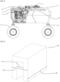
figure 3 montre une vue de côté d'un exemple de l'engin agricole autonome selon l'invention ; - la
figure 4 représente un gabarit de l'engin agricole autonome. - Il faut noter que les figures exposent l'invention de manière détaillée pour permettre de mettre en oeuvre l'invention ; bien que non limitatives, lesdites figures servent notamment à mieux définir l'invention le cas échéant.
- L'invention concerne un engin agricole autonome. Dans un mode de réalisation, l'engin agricole autonome est configuré pour permettre la pulvérisation de produit actif. Dans ce cas, l'engin agricole autonome comprend des réservoirs latéraux contenant un produit de traitement.
- Par exemple, l'engin agricole autonome est un enjambeur quatre roues, autonome, permettant notamment, par exemple, le traitement de vignes. Dans ce cas, les réservoirs latéraux sont notamment disposés de part et d'autre, entre la roue avant et la roue arrière, dans l'empâtement de l'engin agricole autonome de pulvérisation.
- L'engin agricole autonome peut toutefois être configuré pour réaliser d'autres fonctions au moyen d'autres outillages. Par exemple, l'engin agricole autonome peut être équipé d'une rogneuse.
- En référence aux
figures 1 à 3 , la présente invention s'applique à un engin agricole autonome 1 équipé de panneaux récupérateurs et de réservoirs de produit de traitement, l'engin agricole autonome étant configuré pour permettre la pulvérisation d'une parcelle de vignes. Cet exemple est toutefois illustratif. La possibilité d'intégrer des panneaux récupérateurs et des réservoirs latéraux de produit de traitement est avantageuse et cette possibilité constitue un mode de réalisation préféré. Toutefois, l'engin agricole autonome peut être configuré pour réaliser d'autres fonctions. Notamment, l'engin agricole autonome 1 peut ne pas être équipé de panneaux récupérateurs ni de réservoirs de produit, mais être équipé d'un porte-outil sur lequel est monté une rogneuse ou tout autre outil de travail du sol. - Ainsi, l'engin agricole autonome comprend un porte-outil situé dans la voie et dans l'empattement de l'engin, notamment pour porter un outillage disposé sur les flancs de l'engin, à l'intérieur. Le porte-outil peut recevoir un outillage de type rogneuse par exemple. La zone du porte outil peut aussi recevoir des panneaux récupérateurs latéraux, sous lesquels sont disposés des réservoirs latéraux 11, 12.
- L'engin agricole autonome 1 représenté sur les
figures 1 à 3 comprend une ossature 2 ayant une section en U inversé. L'engin agricole autonome 1 présente ici des réservoirs latéraux 11 et 12 destinés à contenir un produit de traitement, notamment un liquide ou une bouillie, pour traiter des cultures, notamment des vignes. - La section en U comprend deux branches verticales et une base horizontale définissant la partie supérieure de l'ossature 2. L'ossature 2 comprend ainsi deux branches définissant les flancs de l'engin agricole autonome 1 et une base définissant un toit de l'engin. L'engin comprend ici quatre roues 13, soit deux roues avant et deux roues arrière. Les roues avant ont un axe de rotation et les roues arrière ont un axe de rotation, les axes de rotation avant et arrière définissant un empattement de l'engin. La largeur de l'ossature 2, correspondant à la distance entre les roues gauche et les roues droites, définit la voie de l'engin agricole autonome 1. L'engin agricole autonome 1 représenté à titre illustratif sur les
figures 1 à 3 forme ainsi un enjambeur autonome 1 de pulvérisation - L'engin agricole autonome 1 de pulvérisation comprend ici des panneaux récupérateurs configurés pour capturer toute gouttelette de produit de traitement traversant la végétation à traiter. Ces panneaux récupérateurs sont de préférence associés à des cuves de récupération disposés en-dessous et reliées à des pompes péristaltiques pour réintroduire le produit de traitement récupéré dans les réservoirs latéraux 11, 12.
- L'engin agricole autonome 1 comprend par ailleurs un système de motorisation fondé sur un moteur thermique 3, notamment de type diesel, avec son système de refroidissement. Le système de motorisation comporte un dispositif d'échappement relié au moteur 3. De préférence, le moteur 3 étant de type diesel, le dispositif d'échappement comprend, à l'extrémité de la tubulure d'échappement 31, un filtre à particules 32. En particulier, le filtre à particules 32 est adapté à la réglementation européenne en matière de moteur thermique de type diesel.
- Le toit de l'engin agricole autonome 1 est de préférence le plus bas possible afin de garantir un centre de gravité le plus bas possible et donc une meilleure stabilité dans la pente et le devers.
- De plus, lorsque l'engin agricole autonome 1 est configuré, comme ici, pour de la pulvérisation, alors les panneaux récupérateurs doivent de préférence être disposés dans l'empattement et dans la voie de l'engin.
- Selon l'invention, le système de motorisation est éclaté : le filtre à air 33 est côté opposé au moteur 3. Cela permet de loger les panneaux récupérateurs dans l'empattement et dans la voie sans augmenter la taille ni la hauteur de l'engin agricole autonome 1. Le moteur 3 est refroidi par un système de refroidissement. Le système de refroidissement est configuré pour refroidir le moteur 3 du système de motorisation, notamment l'eau circulant dans le moteur 3, mais aussi, le cas échéant, l'huile circulant dans des systèmes hydrauliques de l'engin agricole autonome 1 et éventuellement l'air d'admission en sortie d'un turbo lorsque le système de motorisation en est équipé.
- Selon l'invention, le système de refroidissement comprend une galerie de circulation d'air 4 disposée immédiatement sous le toit de l'engin agricole autonome 1.
- La galerie de circulation d'air 4 comprend des couloirs 41 avec des parois fermées et comporte au moins une ouverture 43 pour permettre l'admission d'air extérieur dans la galerie. L'au moins une ouverture 43 peut être grillagée pour éviter l'admission de corps étrangers.
- De préférence, la galerie de circulation d'air 4 comprend deux couloirs latéraux s'étendant sur les flancs de l'engin agricole autonome 1 et un couloir arrière s'étendant transversalement, vers l'arrière de l'engin.
- Les couloirs latéraux et le couloir arrière peuvent chacun comprendre une ouverture 43 d'admission d'air.
- Un avantage de la galerie de circulation d'air 4 située au sommet de l'engin agricole autonome 1 et comprenant des ouvertures 43 d'admission d'air, par définition également au sommet de l'engin, réside dans le fait que l'air aspiré dans la galerie de circulation d'air 4 et permettant le refroidissement du moteur 3 est moins sujet à contenir des résidus végétaux par rapport à des systèmes pour lesquels l'admission d'air est réalisée plus bas, notamment à proximité de la végétation. Le système de refroidissement à air, dans l'invention, est ainsi moins sujet à l'encrassement.
- L'air extérieur, frais, est ainsi admis dans la galerie de circulation d'air 4 et alimente des refroidisseurs pour refroidir les fluides respectifs du moteur 3. L'air chaud est expulsé vers le haut, au-dessus du toit.
- Par exemple, les couloirs 41 formant la galerie comprennent des couloirs longitudinaux et transversaux ménageant des volumes, entre ces couloirs, lesdits volumes 42 recevant des radiateurs configurés pour transmettre à l'air circulant dans la galerie de la chaleur capturée par échange thermique avec l'eau circulant dans le moteur 3 ou avec l'huile circulant dans des circuits hydrauliques de l'engin ou avec l'air d'admission en sortie de turbo du système de motorisation, aux fins de refroidissement de ces éléments. Notamment, il peut être ainsi défini trois volumes 42 pour trois radiateurs.
- L'engin agricole autonome 1 comprend notamment, sur le toit de l'engin, au moins un ventilateur 6, pour mettre en circulation l'air admis dans la galerie de circulation d'air 4. Par exemple, l'engin agricole autonome 1 comporte à cette fin trois ventilateurs électriques 6. Alternativement, l'engin agricole autonome 1 peut comporter à cette fin au moins un ventilateur hydraulique.
- Un avantage de l'invention est que, compte tenu de la disposition de la galerie de circulation d'air 4 au somment de l'engin agricole autonome 1, au niveau du toit correspondant à la base de la forme de U inversé de l'ossature 2, on peut disposer d'une galerie de circulation d'air de grande dimension, notamment s'étendant sensiblement sur toute la largeur de l'engin agricole autonome 1, et sur une portion substantielle de sa longueur. Ainsi, les pertes de charge dans le flux d'air circulant dans ladite galerie de circulation d'air 4 sont réduites. En conséquence, des ventilateurs électriques ne nécessitant pas de courant supérieur à 25 A sont suffisants pour obtenir un fonctionnement adéquate du système de refroidissement, c'est-à-dire pour compenser les pertes de charge et permettre un débit d'air suffisant dans le système de refroidissement pour assurer le refroidissement du moteur 3, dont l'eau circulant dans le moteur et/ou l'huile circulant dans des circuits hydrauliques de l'engin et/ou l'air d'admission en sortie de turbo du système de motorisation.
- Le système de refroidissement est thermiquement connecté au moteur 3, l'eau circulant dans le moteur 3 étant refroidie par l'intermédiaire de l'air frais issu de la galerie de circulation d'air 4. Le système de refroidissement peut également être thermiquement connecté au turbo du système de motorisation, s'il en est équipé, l'air d'admission en sortie du turbo étant refroidi par l'intermédiaire de l'air frais issu de la galerie de circulation d'air 4. Le système de refroidissement peut également être thermiquement connecté à des circuits hydrauliques de l'engin agricole autonome, l'huile circulant dans ces circuits hydrauliques étant refroidie par l'intermédiaire de l'air circulant dans la galerie de circulation d'air 4.
- En outre, dans le cas où le système de motorisation comprend un turbo, l'air d'admission en sortie du turbo peut égalent être refroidi par l'air frais circulant dans la galerie de circulation d'air 4, en particulier au moyen d'un refroidisseur intermédiaire (désigné sous le terme « intercooler » en anglais), permettant de refroidir l'air d'admission en sortie du turbo, et ainsi d'augmenter les performances et la qualité de la combustion dans le moteur 3, et de réduire la consommation.
- Il faut noter que l'absence d'élément en déport améliore la sécurité. En effet, l'engin agricole autonome 1 s'inscrit dans un gabarit, représenté à la
figure 4 . Aucun outillage ni aucun élément ne fait saillie par rapport à ce gabarit 100, tout outillage étant confiné à l'intérieur du tunnel délimité par l'ossature 2. Ainsi, il n'est pas possible qu'un accident survienne à raison d'un outillage situé en déport par rapport à l'ossature 2. Cela simplifie la gestion de la sécurité de l'engin agricole autonome 1. Le gabarit 100 est défini par l'usage souhaité de l'engin agricole autonome 1. En particulier, la largeur intérieure 101 du tunnel défini par le gabarit 100 et l'ossature 2 de l'engin agricole autonome 1 est par exemple adaptée pour enjamber un rang de vignes. La largeur extérieure 102 du gabarit 100 est adaptée pour permettre par exemple la circulation de l'engin agricole autonome 1 entre les rangs adjacents au rang enjambé. - La longueur 103 du gabarit est en outre limitée par l'usage souhaité de l'engin agricole autonome 1. En particulier, la longueur 103 est limitée de sorte que la manoeuvrabilité de l'engin agricole autonome 1 soit adaptée à l'usage, notamment la pulvérisation de vignes.
- L'engin peut ainsi porter des panneaux récupérateurs sans augmenter l'empattement et sans déborder de la voie de l'engin.
- Notamment, l'engin agricole autonome par ailleurs au moins une pompe principale d'avancement, une pompe de gavage de la pompe principale d'avancement et une pompe accessoire disposées dans un volume situé entre la zone porte-outil, où se trouvent par exemple des panneaux récupérateurs, et le toit. La pompe principale d'avancement est notamment configurée pour fournir de l'énergie hydraulique à des systèmes hydrauliques permettant l'avancement de l'engin agricole autonome 1. La pompe accessoire fournit notamment de l'énergie hydraulique à des systèmes hydrauliques permettant l'animation d'outillage monté sur le porte-outil de l'engin agricole autonome 1. Le déport de ces pompes est notamment rendu possible par la mise en oeuvre d'une transmission à courroie ou à chaîne par exemple.
- La puissance du moteur 3 est notamment supérieure à 50 CV. En particulier, le moteur est un moteur diesel.
Claims (10)
- Engin agricole autonome (1) comprenant une ossature (2) ayant une section en U inversé, à laquelle est reliée au moins une roue (13) avant et au moins une roue (13) arrière et définissant une voie, l'ossature (2) présentant deux flancs, correspondant aux branches du U inversé et un toit, correspondant à la base du U inversé,l'engin agricole autonome (1) comprenant par ailleurs un système de motorisation thermique comportant un moteur (3),l'engin agricole autonome (1) comprenant un système de refroidissement ayant une galerie de circulation d'air (4) disposée en partie supérieure de l'ossature (2), directement sous le toit, la galerie de circulation d'air (4) ayant au moins une ouverture (43) pour permettre l'admission d'air extérieur dans la galerie de circulation d'air (4) et une sortie d'air supérieure pour expulser de l'air chaud vers le haut, au-dessus du toit,le système de refroidissement comportant également un dispositif de ventilation pour assurer la circulation d'air dans la galerie de circulation d'air (4),la galerie de circulation d'air (4) étant configurée pour permettre la circulation d'air pour refroidir le moteur (3), notamment pour refroidir un flux d'eau circulant dans le moteur (3) et/ou un flux d'huile circulant dans des circuits hydrauliques de systèmes hydrauliques de l'engin agricole autonome (1).
- Engin agricole autonome (1) selon la revendication 1, dans lequel la galerie de circulation d'air (4) comprend des couloirs (41) longitudinaux et transversaux agencés pour ménager, entre ces couloirs (41), au moins un volume (42), l'engin agricole autonome (1) comprenant au moins un radiateur disposé dans ledit volume (42), de sorte à dissiper de la chaleur dans l'air circulant dans la galerie de circulation d'air (4).
- Engin agricole autonome (1) selon la revendication 1 ou 2, le dispositif de ventilation comprenant au moins un ventilateur (6) disposé au-dessus du toit.
- Engin agricole autonome (1) selon l'une des revendications précédentes, la galerie de circulation d'air (4) ayant une ouverture (43) arrière et deux ouvertures (43) longitudinales pour permettre l'admission d'air extérieur dans la galerie de circulation d'air (4).
- Engin agricole autonome (1) selon l'une des revendications précédentes, l'au moins une ouverture (43) de la galerie de circulation d'air (4) étant fermée par un grillage configuré pour laisser passer l'air et pour bloquer l'admission de corps étrangers dans la galerie de circulation d'air (4).
- Engin agricole autonome (1) selon l'une des revendications précédentes, le système de motorisation comprenant également un dispositif d'échappement et un filtre à air (33), le moteur (3) étant disposé d'un côté de l'ossature (2), c'est-à-dire sensiblement dans l'alignement d'une branche de la section en U de l'ossature (2), et le filtre à air (33) étant disposé à l'opposé du moteur (3), c'est-à-dire sensiblement dans l'alignement d'une branche opposée de la section en U de l'ossature (2), le filtre à air (33) étant relié au moteur (3) par un canal de circulation d'air.
- Engin agricole autonome (1) selon l'une des revendications précédentes, comprenant par ailleurs au moins une pompe principale d'avancement, une pompe de gavage de la pompe principale d'avancement et une pompe accessoire disposée dans un volume situé entre une zone porte-outil, située dans la voie et dans l'empattement de l'engin agricole autonome (1), et le toit, la pompe principale d'avancement étant configurée pour fournir de l'énergie hydraulique à des systèmes hydrauliques permettant l'avancement de l'engin agricole autonome (1) et la pompe accessoire étant configurée pour fournir de l'énergie hydraulique à des systèmes hydrauliques permettant l'animation d'outillage monté sur le porte-outil.
- Engin agricole autonome (1) selon l'une des revendications précédentes, comprenant un turbo et un refroidisseur intermédiaire, dans lequel le système de refroidissement est par ailleurs configuré pour refroidir un flux d'air d'admission en sortie du turbo, le flux d'air d'admission en sortie du turbo étant refroidi par l'air circulant dans la galerie de circulation d'air (4) au moyen du refroidisseur intermédiaire.
- Engin agricole autonome (1) selon l'une des revendications précédentes, le moteur (3) étant un moteur diesel ayant une puissance supérieure à 50 CV.
- Engin agricole autonome (1) selon l'une des revendications précédentes, formant un engin agricole autonome de pulvérisation comprenant deux réservoirs latéraux (11, 12) disposés substantiellement entre la roue (13) avant et la roue (13) arrière, respectivement de chaque côté de l'engin agricole autonome (1) de pulvérisation, l'engin agricole autonome (1) de pulvérisation comprenant par ailleurs un système de pulvérisation, le système de pulvérisation comprenant au moins deux panneaux récupérateurs latéraux, les réservoirs latéraux (11, 12) et les panneaux récupérateurs étant situés dans la voie de l'engin agricole autonome (1) de pulvérisation, correspondant à sa largeur (102), sensiblement dans l'alignement de chaque flanc défini par l'ossature (2), de chaque côté de l'engin agricole autonome (1) de pulvérisation.
Applications Claiming Priority (1)
| Application Number | Priority Date | Filing Date | Title |
|---|---|---|---|
| FR2212419A FR3142441B1 (fr) | 2022-11-28 | 2022-11-28 | Engin agricole autonome équipé d’un système de motorisation éclaté |
Publications (2)
| Publication Number | Publication Date |
|---|---|
| EP4375106A1 true EP4375106A1 (fr) | 2024-05-29 |
| EP4375106B1 EP4375106B1 (fr) | 2025-06-04 |
Family
ID=85175865
Family Applications (1)
| Application Number | Title | Priority Date | Filing Date |
|---|---|---|---|
| EP23203428.0A Active EP4375106B1 (fr) | 2022-11-28 | 2023-10-13 | Engin agricole autonome équipé d'un système de motorisation éclaté |
Country Status (6)
| Country | Link |
|---|---|
| US (1) | US12385453B2 (fr) |
| EP (1) | EP4375106B1 (fr) |
| JP (1) | JP2024077604A (fr) |
| AU (1) | AU2023254859A1 (fr) |
| ES (1) | ES3038654T3 (fr) |
| FR (1) | FR3142441B1 (fr) |
Citations (6)
| Publication number | Priority date | Publication date | Assignee | Title |
|---|---|---|---|---|
| FR2608989A1 (fr) * | 1986-12-26 | 1988-07-01 | Poncin Gilles | Tracteur enjambeur a chenilles |
| EP1496214A1 (fr) * | 2003-07-11 | 2005-01-12 | Deere & Company | Véhicule tous terrains |
| DE102009023771A1 (de) * | 2009-06-03 | 2010-12-09 | Claas Selbstfahrende Erntemaschinen Gmbh | Erntemaschine mit Kühleraggregat |
| EP3210467A1 (fr) * | 2016-02-23 | 2017-08-30 | Yanmar Co., Ltd. | Vehicule de travail |
| WO2017201445A1 (fr) * | 2016-05-19 | 2017-11-23 | Vermeer Manufacturing Company | Véhicules autopropulsés |
| EP3987898A1 (fr) * | 2019-06-20 | 2022-04-27 | Yanmar Power Technology Co., Ltd. | Système de conduite automatique pour véhicule de travail |
Family Cites Families (3)
| Publication number | Priority date | Publication date | Assignee | Title |
|---|---|---|---|---|
| US9731591B2 (en) * | 2015-04-28 | 2017-08-15 | Cnh Industrial America Llc | Heat transfer airflow through engine compartment |
| JP6448507B2 (ja) * | 2015-10-20 | 2019-01-09 | ヤンマー株式会社 | 作業車両 |
| JP7134121B2 (ja) * | 2019-03-22 | 2022-09-09 | ヤンマーパワーテクノロジー株式会社 | 農作業用車両 |
-
2022
- 2022-11-28 FR FR2212419A patent/FR3142441B1/fr active Active
-
2023
- 2023-10-13 EP EP23203428.0A patent/EP4375106B1/fr active Active
- 2023-10-13 ES ES23203428T patent/ES3038654T3/es active Active
- 2023-10-23 AU AU2023254859A patent/AU2023254859A1/en active Pending
- 2023-10-31 US US18/498,393 patent/US12385453B2/en active Active
- 2023-11-10 JP JP2023192515A patent/JP2024077604A/ja active Pending
Patent Citations (6)
| Publication number | Priority date | Publication date | Assignee | Title |
|---|---|---|---|---|
| FR2608989A1 (fr) * | 1986-12-26 | 1988-07-01 | Poncin Gilles | Tracteur enjambeur a chenilles |
| EP1496214A1 (fr) * | 2003-07-11 | 2005-01-12 | Deere & Company | Véhicule tous terrains |
| DE102009023771A1 (de) * | 2009-06-03 | 2010-12-09 | Claas Selbstfahrende Erntemaschinen Gmbh | Erntemaschine mit Kühleraggregat |
| EP3210467A1 (fr) * | 2016-02-23 | 2017-08-30 | Yanmar Co., Ltd. | Vehicule de travail |
| WO2017201445A1 (fr) * | 2016-05-19 | 2017-11-23 | Vermeer Manufacturing Company | Véhicules autopropulsés |
| EP3987898A1 (fr) * | 2019-06-20 | 2022-04-27 | Yanmar Power Technology Co., Ltd. | Système de conduite automatique pour véhicule de travail |
Also Published As
| Publication number | Publication date |
|---|---|
| JP2024077604A (ja) | 2024-06-07 |
| FR3142441A1 (fr) | 2024-05-31 |
| ES3038654T3 (en) | 2025-10-14 |
| EP4375106B1 (fr) | 2025-06-04 |
| FR3142441B1 (fr) | 2024-11-15 |
| US20240175414A1 (en) | 2024-05-30 |
| AU2023254859A1 (en) | 2024-06-13 |
| US12385453B2 (en) | 2025-08-12 |
Similar Documents
| Publication | Publication Date | Title |
|---|---|---|
| EP2726805B1 (fr) | Lame d'echangeur de chaleur a zone de contournement | |
| EP2558353B1 (fr) | Appareil de traction compact | |
| FR3021911A1 (fr) | Machine de travail mobile, notamment sous la forme d'un camion a benne ou camion | |
| WO2012010939A1 (fr) | Moteur hydraulique, production electrique, air, climatisation, chauffage | |
| EP3409524A1 (fr) | Dispositif de contrôle du flux d'air dans un bloc moteur de véhicule automobile | |
| EP4375106B1 (fr) | Engin agricole autonome équipé d'un système de motorisation éclaté | |
| FR3132001A1 (fr) | Support de circuit de fluide diélectrique et ensemble de régulation thermique correspondant, notamment pour véhicule automobile | |
| FR2737838A1 (fr) | Systeme de refroidissement integre pour convertisseur de puissance utilisant l'air d'admission d'une turbine | |
| FR2875376A1 (fr) | Tondeuse a gazon avec moteur dispose a l'arriere du siege conducteur | |
| FR2774463A1 (fr) | Module echangeur refroidisseur de fluide et utilisation du module echangeur refroidisseur | |
| FR3131870A1 (fr) | Dispositif de régulation thermique, notamment pour véhicule automobile, et ensemble de régulation thermique correspondant | |
| EP0727033A1 (fr) | Refrigerant atmospherique humide a dispositif antigel | |
| FR3140479A1 (fr) | dispositif de régulation thermique comprenant un collecteur de sortie positionné sous le bloc batterie. | |
| FR3082791A1 (fr) | Vehicule pour transport de conteneur a moteur electrique et a batterie | |
| FR3062164A1 (fr) | Appareil de recuperation de chaleur d'echappement | |
| EP4288645B1 (fr) | Plaque anti-émulsion avec passage gaz blow-by | |
| EP1769145B1 (fr) | Dispositif de regulation thermique d'un moteur a combustion interne | |
| EP1774149A1 (fr) | Dispositif de regulation thermique d'un moteur a combustion interne | |
| FR3101684A1 (fr) | Dispositif amélioré de lubrification et de refroidissement pour roulements de turbomachine d’aéronef | |
| WO2022112674A1 (fr) | Dispositif anti-recyclage à amélioration d'admission d'air | |
| FR3134761A1 (fr) | Engin agricole autonome comprenant un système de motorisation principal à hydrogène | |
| EP2927991B1 (fr) | Dispositif de stockage de cellules de batterie | |
| EP4385830A1 (fr) | Obturateur pour grille d' entrée d' air de pare-chocs de véhicule automobile | |
| FR3137130A1 (fr) | DISPOSITIF DE REFROIDISSEMENT DU MOTEUR DES vÉhicules automobiles | |
| WO2024074500A1 (fr) | Dispositif de refroidissement pour module de batterie |
Legal Events
| Date | Code | Title | Description |
|---|---|---|---|
| PUAI | Public reference made under article 153(3) epc to a published international application that has entered the european phase |
Free format text: ORIGINAL CODE: 0009012 |
|
| STAA | Information on the status of an ep patent application or granted ep patent |
Free format text: STATUS: THE APPLICATION HAS BEEN PUBLISHED |
|
| AK | Designated contracting states |
Kind code of ref document: A1 Designated state(s): AL AT BE BG CH CY CZ DE DK EE ES FI FR GB GR HR HU IE IS IT LI LT LU LV MC ME MK MT NL NO PL PT RO RS SE SI SK SM TR |
|
| STAA | Information on the status of an ep patent application or granted ep patent |
Free format text: STATUS: REQUEST FOR EXAMINATION WAS MADE |
|
| 17P | Request for examination filed |
Effective date: 20241114 |
|
| RBV | Designated contracting states (corrected) |
Designated state(s): AL AT BE BG CH CY CZ DE DK EE ES FI FR GB GR HR HU IE IS IT LI LT LU LV MC ME MK MT NL NO PL PT RO RS SE SI SK SM TR |
|
| GRAP | Despatch of communication of intention to grant a patent |
Free format text: ORIGINAL CODE: EPIDOSNIGR1 |
|
| STAA | Information on the status of an ep patent application or granted ep patent |
Free format text: STATUS: GRANT OF PATENT IS INTENDED |
|
| RIC1 | Information provided on ipc code assigned before grant |
Ipc: F02M 35/04 20060101ALI20250306BHEP Ipc: B62D 49/06 20060101ALI20250306BHEP Ipc: B60K 11/06 20060101ALI20250306BHEP Ipc: A01M 7/00 20060101ALI20250306BHEP Ipc: B60K 17/10 20060101ALI20250306BHEP Ipc: F02B 29/04 20060101ALI20250306BHEP Ipc: F02M 35/16 20060101ALI20250306BHEP Ipc: F02M 35/024 20060101ALI20250306BHEP Ipc: F02M 35/10 20060101ALI20250306BHEP Ipc: B60K 13/02 20060101ALI20250306BHEP Ipc: B60K 11/04 20060101ALI20250306BHEP Ipc: B60K 11/08 20060101AFI20250306BHEP |
|
| GRAS | Grant fee paid |
Free format text: ORIGINAL CODE: EPIDOSNIGR3 |
|
| INTG | Intention to grant announced |
Effective date: 20250327 |
|
| GRAA | (expected) grant |
Free format text: ORIGINAL CODE: 0009210 |
|
| STAA | Information on the status of an ep patent application or granted ep patent |
Free format text: STATUS: THE PATENT HAS BEEN GRANTED |
|
| AK | Designated contracting states |
Kind code of ref document: B1 Designated state(s): AL AT BE BG CH CY CZ DE DK EE ES FI FR GB GR HR HU IE IS IT LI LT LU LV MC ME MK MT NL NO PL PT RO RS SE SI SK SM TR |
|
| REG | Reference to a national code |
Ref country code: GB Ref legal event code: FG4D Free format text: NOT ENGLISH |
|
| REG | Reference to a national code |
Ref country code: CH Ref legal event code: EP |
|
| REG | Reference to a national code |
Ref country code: DE Ref legal event code: R096 Ref document number: 602023003834 Country of ref document: DE |
|
| REG | Reference to a national code |
Ref country code: IE Ref legal event code: FG4D Free format text: LANGUAGE OF EP DOCUMENT: FRENCH |
|
| REG | Reference to a national code |
Ref country code: NL Ref legal event code: MP Effective date: 20250604 |
|
| PG25 | Lapsed in a contracting state [announced via postgrant information from national office to epo] |
Ref country code: FI Free format text: LAPSE BECAUSE OF FAILURE TO SUBMIT A TRANSLATION OF THE DESCRIPTION OR TO PAY THE FEE WITHIN THE PRESCRIBED TIME-LIMIT Effective date: 20250604 |
|
| REG | Reference to a national code |
Ref country code: LT Ref legal event code: MG9D |
|
| PG25 | Lapsed in a contracting state [announced via postgrant information from national office to epo] |
Ref country code: NO Free format text: LAPSE BECAUSE OF FAILURE TO SUBMIT A TRANSLATION OF THE DESCRIPTION OR TO PAY THE FEE WITHIN THE PRESCRIBED TIME-LIMIT Effective date: 20250904 Ref country code: GR Free format text: LAPSE BECAUSE OF FAILURE TO SUBMIT A TRANSLATION OF THE DESCRIPTION OR TO PAY THE FEE WITHIN THE PRESCRIBED TIME-LIMIT Effective date: 20250905 |
|
| REG | Reference to a national code |
Ref country code: ES Ref legal event code: FG2A Ref document number: 3038654 Country of ref document: ES Kind code of ref document: T3 Effective date: 20251014 |
|
| PG25 | Lapsed in a contracting state [announced via postgrant information from national office to epo] |
Ref country code: PL Free format text: LAPSE BECAUSE OF FAILURE TO SUBMIT A TRANSLATION OF THE DESCRIPTION OR TO PAY THE FEE WITHIN THE PRESCRIBED TIME-LIMIT Effective date: 20250604 |
|
| PG25 | Lapsed in a contracting state [announced via postgrant information from national office to epo] |
Ref country code: BG Free format text: LAPSE BECAUSE OF FAILURE TO SUBMIT A TRANSLATION OF THE DESCRIPTION OR TO PAY THE FEE WITHIN THE PRESCRIBED TIME-LIMIT Effective date: 20250604 |
|
| PG25 | Lapsed in a contracting state [announced via postgrant information from national office to epo] |
Ref country code: HR Free format text: LAPSE BECAUSE OF FAILURE TO SUBMIT A TRANSLATION OF THE DESCRIPTION OR TO PAY THE FEE WITHIN THE PRESCRIBED TIME-LIMIT Effective date: 20250604 |
|
| PG25 | Lapsed in a contracting state [announced via postgrant information from national office to epo] |
Ref country code: RS Free format text: LAPSE BECAUSE OF FAILURE TO SUBMIT A TRANSLATION OF THE DESCRIPTION OR TO PAY THE FEE WITHIN THE PRESCRIBED TIME-LIMIT Effective date: 20250904 |
|
| PG25 | Lapsed in a contracting state [announced via postgrant information from national office to epo] |
Ref country code: LV Free format text: LAPSE BECAUSE OF FAILURE TO SUBMIT A TRANSLATION OF THE DESCRIPTION OR TO PAY THE FEE WITHIN THE PRESCRIBED TIME-LIMIT Effective date: 20250604 |
|
| PG25 | Lapsed in a contracting state [announced via postgrant information from national office to epo] |
Ref country code: NL Free format text: LAPSE BECAUSE OF FAILURE TO SUBMIT A TRANSLATION OF THE DESCRIPTION OR TO PAY THE FEE WITHIN THE PRESCRIBED TIME-LIMIT Effective date: 20250604 |
|
| PG25 | Lapsed in a contracting state [announced via postgrant information from national office to epo] |
Ref country code: PT Free format text: LAPSE BECAUSE OF FAILURE TO SUBMIT A TRANSLATION OF THE DESCRIPTION OR TO PAY THE FEE WITHIN THE PRESCRIBED TIME-LIMIT Effective date: 20251006 |
|
| REG | Reference to a national code |
Ref country code: AT Ref legal event code: MK05 Ref document number: 1800034 Country of ref document: AT Kind code of ref document: T Effective date: 20250604 |
|
| PG25 | Lapsed in a contracting state [announced via postgrant information from national office to epo] |
Ref country code: IS Free format text: LAPSE BECAUSE OF FAILURE TO SUBMIT A TRANSLATION OF THE DESCRIPTION OR TO PAY THE FEE WITHIN THE PRESCRIBED TIME-LIMIT Effective date: 20251004 |
|
| PG25 | Lapsed in a contracting state [announced via postgrant information from national office to epo] |
Ref country code: SM Free format text: LAPSE BECAUSE OF FAILURE TO SUBMIT A TRANSLATION OF THE DESCRIPTION OR TO PAY THE FEE WITHIN THE PRESCRIBED TIME-LIMIT Effective date: 20250604 Ref country code: AT Free format text: LAPSE BECAUSE OF FAILURE TO SUBMIT A TRANSLATION OF THE DESCRIPTION OR TO PAY THE FEE WITHIN THE PRESCRIBED TIME-LIMIT Effective date: 20250604 |
|
| PGFP | Annual fee paid to national office [announced via postgrant information from national office to epo] |
Ref country code: IT Payment date: 20251031 Year of fee payment: 3 |
|
| PGFP | Annual fee paid to national office [announced via postgrant information from national office to epo] |
Ref country code: FR Payment date: 20251027 Year of fee payment: 3 |
|
| PG25 | Lapsed in a contracting state [announced via postgrant information from national office to epo] |
Ref country code: CZ Free format text: LAPSE BECAUSE OF FAILURE TO SUBMIT A TRANSLATION OF THE DESCRIPTION OR TO PAY THE FEE WITHIN THE PRESCRIBED TIME-LIMIT Effective date: 20250604 |
|
| PG25 | Lapsed in a contracting state [announced via postgrant information from national office to epo] |
Ref country code: EE Free format text: LAPSE BECAUSE OF FAILURE TO SUBMIT A TRANSLATION OF THE DESCRIPTION OR TO PAY THE FEE WITHIN THE PRESCRIBED TIME-LIMIT Effective date: 20250604 |
|
| PG25 | Lapsed in a contracting state [announced via postgrant information from national office to epo] |
Ref country code: SK Free format text: LAPSE BECAUSE OF FAILURE TO SUBMIT A TRANSLATION OF THE DESCRIPTION OR TO PAY THE FEE WITHIN THE PRESCRIBED TIME-LIMIT Effective date: 20250604 |
|
| PGFP | Annual fee paid to national office [announced via postgrant information from national office to epo] |
Ref country code: ES Payment date: 20251110 Year of fee payment: 3 |
|
| REG | Reference to a national code |
Ref country code: DE Ref legal event code: R097 Ref document number: 602023003834 Country of ref document: DE |
|
| PG25 | Lapsed in a contracting state [announced via postgrant information from national office to epo] |
Ref country code: RO Free format text: LAPSE BECAUSE OF FAILURE TO SUBMIT A TRANSLATION OF THE DESCRIPTION OR TO PAY THE FEE WITHIN THE PRESCRIBED TIME-LIMIT Effective date: 20250604 |
|
| PLBE | No opposition filed within time limit |
Free format text: ORIGINAL CODE: 0009261 |
|
| STAA | Information on the status of an ep patent application or granted ep patent |
Free format text: STATUS: NO OPPOSITION FILED WITHIN TIME LIMIT |
|
| PG25 | Lapsed in a contracting state [announced via postgrant information from national office to epo] |
Ref country code: DK Free format text: LAPSE BECAUSE OF FAILURE TO SUBMIT A TRANSLATION OF THE DESCRIPTION OR TO PAY THE FEE WITHIN THE PRESCRIBED TIME-LIMIT Effective date: 20250604 |
|
| REG | Reference to a national code |
Ref country code: CH Ref legal event code: L10 Free format text: ST27 STATUS EVENT CODE: U-0-0-L10-L00 (AS PROVIDED BY THE NATIONAL OFFICE) Effective date: 20260416 |
|
| REG | Reference to a national code |
Ref country code: DE Ref legal event code: R119 Ref document number: 602023003834 Country of ref document: DE |
|
| 26N | No opposition filed |
Effective date: 20260305 |
|
| PG25 | Lapsed in a contracting state [announced via postgrant information from national office to epo] |
Ref country code: LU Free format text: LAPSE BECAUSE OF NON-PAYMENT OF DUE FEES Effective date: 20251013 |
|
| REG | Reference to a national code |
Ref country code: BE Ref legal event code: MM Effective date: 20251031 |
|
| PG25 | Lapsed in a contracting state [announced via postgrant information from national office to epo] |
Ref country code: LT Free format text: LAPSE BECAUSE OF FAILURE TO SUBMIT A TRANSLATION OF THE DESCRIPTION OR TO PAY THE FEE WITHIN THE PRESCRIBED TIME-LIMIT Effective date: 20250604 |
|
| PG25 | Lapsed in a contracting state [announced via postgrant information from national office to epo] |
Ref country code: MC Free format text: LAPSE BECAUSE OF FAILURE TO SUBMIT A TRANSLATION OF THE DESCRIPTION OR TO PAY THE FEE WITHIN THE PRESCRIBED TIME-LIMIT Effective date: 20250604 |
|
| PG25 | Lapsed in a contracting state [announced via postgrant information from national office to epo] |
Ref country code: DE Free format text: LAPSE BECAUSE OF NON-PAYMENT OF DUE FEES Effective date: 20260501 |
|
| PG25 | Lapsed in a contracting state [announced via postgrant information from national office to epo] |
Ref country code: BE Free format text: LAPSE BECAUSE OF NON-PAYMENT OF DUE FEES Effective date: 20251031 |
|
| PG25 | Lapsed in a contracting state [announced via postgrant information from national office to epo] |
Ref country code: SE Free format text: LAPSE BECAUSE OF FAILURE TO SUBMIT A TRANSLATION OF THE DESCRIPTION OR TO PAY THE FEE WITHIN THE PRESCRIBED TIME-LIMIT Effective date: 20250604 |