EP4375057A1 - Rubber die for use in cold isotropic pressure molding, production method for material for ceramic balls, and production method for ceramic balls - Google Patents
Rubber die for use in cold isotropic pressure molding, production method for material for ceramic balls, and production method for ceramic balls Download PDFInfo
- Publication number
- EP4375057A1 EP4375057A1 EP22845973.1A EP22845973A EP4375057A1 EP 4375057 A1 EP4375057 A1 EP 4375057A1 EP 22845973 A EP22845973 A EP 22845973A EP 4375057 A1 EP4375057 A1 EP 4375057A1
- Authority
- EP
- European Patent Office
- Prior art keywords
- rubber mold
- green compact
- isostatic pressing
- cold isostatic
- hole section
- Prior art date
- Legal status (The legal status is an assumption and is not a legal conclusion. Google has not performed a legal analysis and makes no representation as to the accuracy of the status listed.)
- Pending
Links
Images





Classifications
-
- B—PERFORMING OPERATIONS; TRANSPORTING
- B30—PRESSES
- B30B—PRESSES IN GENERAL
- B30B11/00—Presses specially adapted for forming shaped articles from material in particulate or plastic state, e.g. briquetting presses, tabletting presses
- B30B11/001—Presses specially adapted for forming shaped articles from material in particulate or plastic state, e.g. briquetting presses, tabletting presses using a flexible element, e.g. diaphragm, urged by fluid pressure; Isostatic presses
-
- B—PERFORMING OPERATIONS; TRANSPORTING
- B28—WORKING CEMENT, CLAY, OR STONE
- B28B—SHAPING CLAY OR OTHER CERAMIC COMPOSITIONS; SHAPING SLAG; SHAPING MIXTURES CONTAINING CEMENTITIOUS MATERIAL, e.g. PLASTER
- B28B11/00—Apparatus or processes for treating or working the shaped or preshaped articles
- B28B11/08—Apparatus or processes for treating or working the shaped or preshaped articles for reshaping the surface, e.g. smoothing, roughening, corrugating, making screw-threads
- B28B11/10—Apparatus or processes for treating or working the shaped or preshaped articles for reshaping the surface, e.g. smoothing, roughening, corrugating, making screw-threads by using presses
-
- B—PERFORMING OPERATIONS; TRANSPORTING
- B28—WORKING CEMENT, CLAY, OR STONE
- B28B—SHAPING CLAY OR OTHER CERAMIC COMPOSITIONS; SHAPING SLAG; SHAPING MIXTURES CONTAINING CEMENTITIOUS MATERIAL, e.g. PLASTER
- B28B3/00—Producing shaped articles from the material by using presses; Presses specially adapted therefor
- B28B3/003—Pressing by means acting upon the material via flexible mould wall parts, e.g. by means of inflatable cores, isostatic presses
-
- B—PERFORMING OPERATIONS; TRANSPORTING
- B30—PRESSES
- B30B—PRESSES IN GENERAL
- B30B15/00—Details of, or accessories for, presses; Auxiliary measures in connection with pressing
- B30B15/02—Dies; Inserts therefor; Mounting thereof; Moulds
- B30B15/022—Moulds for compacting material in powder, granular of pasta form
- B30B15/024—Moulds for compacting material in powder, granular of pasta form using elastic mould parts
-
- B—PERFORMING OPERATIONS; TRANSPORTING
- B30—PRESSES
- B30B—PRESSES IN GENERAL
- B30B5/00—Presses characterised by the use of pressing means other than those mentioned in the preceding groups
- B30B5/02—Presses characterised by the use of pressing means other than those mentioned in the preceding groups wherein the pressing means is in the form of a flexible element, e.g. diaphragm, urged by fluid pressure
-
- C—CHEMISTRY; METALLURGY
- C04—CEMENTS; CONCRETE; ARTIFICIAL STONE; CERAMICS; REFRACTORIES
- C04B—LIME, MAGNESIA; SLAG; CEMENTS; COMPOSITIONS THEREOF, e.g. MORTARS, CONCRETE OR LIKE BUILDING MATERIALS; ARTIFICIAL STONE; CERAMICS; REFRACTORIES; TREATMENT OF NATURAL STONE
- C04B35/00—Shaped ceramic products characterised by their composition; Ceramics compositions; Processing powders of inorganic compounds preparatory to the manufacturing of ceramic products
- C04B35/01—Shaped ceramic products characterised by their composition; Ceramics compositions; Processing powders of inorganic compounds preparatory to the manufacturing of ceramic products based on oxide ceramics
- C04B35/10—Shaped ceramic products characterised by their composition; Ceramics compositions; Processing powders of inorganic compounds preparatory to the manufacturing of ceramic products based on oxide ceramics based on aluminium oxide
-
- C—CHEMISTRY; METALLURGY
- C04—CEMENTS; CONCRETE; ARTIFICIAL STONE; CERAMICS; REFRACTORIES
- C04B—LIME, MAGNESIA; SLAG; CEMENTS; COMPOSITIONS THEREOF, e.g. MORTARS, CONCRETE OR LIKE BUILDING MATERIALS; ARTIFICIAL STONE; CERAMICS; REFRACTORIES; TREATMENT OF NATURAL STONE
- C04B35/00—Shaped ceramic products characterised by their composition; Ceramics compositions; Processing powders of inorganic compounds preparatory to the manufacturing of ceramic products
- C04B35/01—Shaped ceramic products characterised by their composition; Ceramics compositions; Processing powders of inorganic compounds preparatory to the manufacturing of ceramic products based on oxide ceramics
- C04B35/10—Shaped ceramic products characterised by their composition; Ceramics compositions; Processing powders of inorganic compounds preparatory to the manufacturing of ceramic products based on oxide ceramics based on aluminium oxide
- C04B35/111—Fine ceramics
-
- C—CHEMISTRY; METALLURGY
- C04—CEMENTS; CONCRETE; ARTIFICIAL STONE; CERAMICS; REFRACTORIES
- C04B—LIME, MAGNESIA; SLAG; CEMENTS; COMPOSITIONS THEREOF, e.g. MORTARS, CONCRETE OR LIKE BUILDING MATERIALS; ARTIFICIAL STONE; CERAMICS; REFRACTORIES; TREATMENT OF NATURAL STONE
- C04B35/00—Shaped ceramic products characterised by their composition; Ceramics compositions; Processing powders of inorganic compounds preparatory to the manufacturing of ceramic products
- C04B35/01—Shaped ceramic products characterised by their composition; Ceramics compositions; Processing powders of inorganic compounds preparatory to the manufacturing of ceramic products based on oxide ceramics
- C04B35/48—Shaped ceramic products characterised by their composition; Ceramics compositions; Processing powders of inorganic compounds preparatory to the manufacturing of ceramic products based on oxide ceramics based on zirconium or hafnium oxides, zirconates, zircon or hafnates
-
- C—CHEMISTRY; METALLURGY
- C04—CEMENTS; CONCRETE; ARTIFICIAL STONE; CERAMICS; REFRACTORIES
- C04B—LIME, MAGNESIA; SLAG; CEMENTS; COMPOSITIONS THEREOF, e.g. MORTARS, CONCRETE OR LIKE BUILDING MATERIALS; ARTIFICIAL STONE; CERAMICS; REFRACTORIES; TREATMENT OF NATURAL STONE
- C04B35/00—Shaped ceramic products characterised by their composition; Ceramics compositions; Processing powders of inorganic compounds preparatory to the manufacturing of ceramic products
- C04B35/01—Shaped ceramic products characterised by their composition; Ceramics compositions; Processing powders of inorganic compounds preparatory to the manufacturing of ceramic products based on oxide ceramics
- C04B35/48—Shaped ceramic products characterised by their composition; Ceramics compositions; Processing powders of inorganic compounds preparatory to the manufacturing of ceramic products based on oxide ceramics based on zirconium or hafnium oxides, zirconates, zircon or hafnates
- C04B35/486—Fine ceramics
-
- C—CHEMISTRY; METALLURGY
- C04—CEMENTS; CONCRETE; ARTIFICIAL STONE; CERAMICS; REFRACTORIES
- C04B—LIME, MAGNESIA; SLAG; CEMENTS; COMPOSITIONS THEREOF, e.g. MORTARS, CONCRETE OR LIKE BUILDING MATERIALS; ARTIFICIAL STONE; CERAMICS; REFRACTORIES; TREATMENT OF NATURAL STONE
- C04B35/00—Shaped ceramic products characterised by their composition; Ceramics compositions; Processing powders of inorganic compounds preparatory to the manufacturing of ceramic products
- C04B35/515—Shaped ceramic products characterised by their composition; Ceramics compositions; Processing powders of inorganic compounds preparatory to the manufacturing of ceramic products based on non-oxide ceramics
- C04B35/58—Shaped ceramic products characterised by their composition; Ceramics compositions; Processing powders of inorganic compounds preparatory to the manufacturing of ceramic products based on non-oxide ceramics based on borides, nitrides, i.e. nitrides, oxynitrides, carbonitrides or oxycarbonitrides or silicides
- C04B35/583—Shaped ceramic products characterised by their composition; Ceramics compositions; Processing powders of inorganic compounds preparatory to the manufacturing of ceramic products based on non-oxide ceramics based on borides, nitrides, i.e. nitrides, oxynitrides, carbonitrides or oxycarbonitrides or silicides based on boron nitride
-
- C—CHEMISTRY; METALLURGY
- C04—CEMENTS; CONCRETE; ARTIFICIAL STONE; CERAMICS; REFRACTORIES
- C04B—LIME, MAGNESIA; SLAG; CEMENTS; COMPOSITIONS THEREOF, e.g. MORTARS, CONCRETE OR LIKE BUILDING MATERIALS; ARTIFICIAL STONE; CERAMICS; REFRACTORIES; TREATMENT OF NATURAL STONE
- C04B35/00—Shaped ceramic products characterised by their composition; Ceramics compositions; Processing powders of inorganic compounds preparatory to the manufacturing of ceramic products
- C04B35/515—Shaped ceramic products characterised by their composition; Ceramics compositions; Processing powders of inorganic compounds preparatory to the manufacturing of ceramic products based on non-oxide ceramics
- C04B35/58—Shaped ceramic products characterised by their composition; Ceramics compositions; Processing powders of inorganic compounds preparatory to the manufacturing of ceramic products based on non-oxide ceramics based on borides, nitrides, i.e. nitrides, oxynitrides, carbonitrides or oxycarbonitrides or silicides
- C04B35/584—Shaped ceramic products characterised by their composition; Ceramics compositions; Processing powders of inorganic compounds preparatory to the manufacturing of ceramic products based on non-oxide ceramics based on borides, nitrides, i.e. nitrides, oxynitrides, carbonitrides or oxycarbonitrides or silicides based on silicon nitride
-
- C—CHEMISTRY; METALLURGY
- C04—CEMENTS; CONCRETE; ARTIFICIAL STONE; CERAMICS; REFRACTORIES
- C04B—LIME, MAGNESIA; SLAG; CEMENTS; COMPOSITIONS THEREOF, e.g. MORTARS, CONCRETE OR LIKE BUILDING MATERIALS; ARTIFICIAL STONE; CERAMICS; REFRACTORIES; TREATMENT OF NATURAL STONE
- C04B35/00—Shaped ceramic products characterised by their composition; Ceramics compositions; Processing powders of inorganic compounds preparatory to the manufacturing of ceramic products
- C04B35/515—Shaped ceramic products characterised by their composition; Ceramics compositions; Processing powders of inorganic compounds preparatory to the manufacturing of ceramic products based on non-oxide ceramics
- C04B35/58—Shaped ceramic products characterised by their composition; Ceramics compositions; Processing powders of inorganic compounds preparatory to the manufacturing of ceramic products based on non-oxide ceramics based on borides, nitrides, i.e. nitrides, oxynitrides, carbonitrides or oxycarbonitrides or silicides
- C04B35/584—Shaped ceramic products characterised by their composition; Ceramics compositions; Processing powders of inorganic compounds preparatory to the manufacturing of ceramic products based on non-oxide ceramics based on borides, nitrides, i.e. nitrides, oxynitrides, carbonitrides or oxycarbonitrides or silicides based on silicon nitride
- C04B35/593—Shaped ceramic products characterised by their composition; Ceramics compositions; Processing powders of inorganic compounds preparatory to the manufacturing of ceramic products based on non-oxide ceramics based on borides, nitrides, i.e. nitrides, oxynitrides, carbonitrides or oxycarbonitrides or silicides based on silicon nitride obtained by pressure sintering
-
- C—CHEMISTRY; METALLURGY
- C04—CEMENTS; CONCRETE; ARTIFICIAL STONE; CERAMICS; REFRACTORIES
- C04B—LIME, MAGNESIA; SLAG; CEMENTS; COMPOSITIONS THEREOF, e.g. MORTARS, CONCRETE OR LIKE BUILDING MATERIALS; ARTIFICIAL STONE; CERAMICS; REFRACTORIES; TREATMENT OF NATURAL STONE
- C04B35/00—Shaped ceramic products characterised by their composition; Ceramics compositions; Processing powders of inorganic compounds preparatory to the manufacturing of ceramic products
- C04B35/622—Forming processes; Processing powders of inorganic compounds preparatory to the manufacturing of ceramic products
- C04B35/64—Burning or sintering processes
- C04B35/645—Pressure sintering
-
- C—CHEMISTRY; METALLURGY
- C04—CEMENTS; CONCRETE; ARTIFICIAL STONE; CERAMICS; REFRACTORIES
- C04B—LIME, MAGNESIA; SLAG; CEMENTS; COMPOSITIONS THEREOF, e.g. MORTARS, CONCRETE OR LIKE BUILDING MATERIALS; ARTIFICIAL STONE; CERAMICS; REFRACTORIES; TREATMENT OF NATURAL STONE
- C04B35/00—Shaped ceramic products characterised by their composition; Ceramics compositions; Processing powders of inorganic compounds preparatory to the manufacturing of ceramic products
- C04B35/622—Forming processes; Processing powders of inorganic compounds preparatory to the manufacturing of ceramic products
- C04B35/64—Burning or sintering processes
- C04B35/645—Pressure sintering
- C04B35/6455—Hot isostatic pressing
-
- F—MECHANICAL ENGINEERING; LIGHTING; HEATING; WEAPONS; BLASTING
- F16—ENGINEERING ELEMENTS AND UNITS; GENERAL MEASURES FOR PRODUCING AND MAINTAINING EFFECTIVE FUNCTIONING OF MACHINES OR INSTALLATIONS; THERMAL INSULATION IN GENERAL
- F16C—SHAFTS; FLEXIBLE SHAFTS; ELEMENTS OR CRANKSHAFT MECHANISMS; ROTARY BODIES OTHER THAN GEARING ELEMENTS; BEARINGS
- F16C33/00—Parts of bearings; Special methods for making bearings or parts thereof
- F16C33/30—Parts of ball or roller bearings
- F16C33/32—Balls
-
- C—CHEMISTRY; METALLURGY
- C04—CEMENTS; CONCRETE; ARTIFICIAL STONE; CERAMICS; REFRACTORIES
- C04B—LIME, MAGNESIA; SLAG; CEMENTS; COMPOSITIONS THEREOF, e.g. MORTARS, CONCRETE OR LIKE BUILDING MATERIALS; ARTIFICIAL STONE; CERAMICS; REFRACTORIES; TREATMENT OF NATURAL STONE
- C04B2235/00—Aspects relating to ceramic starting mixtures or sintered ceramic products
- C04B2235/02—Composition of constituents of the starting material or of secondary phases of the final product
- C04B2235/30—Constituents and secondary phases not being of a fibrous nature
- C04B2235/38—Non-oxide ceramic constituents or additives
- C04B2235/3852—Nitrides, e.g. oxynitrides, carbonitrides, oxycarbonitrides, lithium nitride, magnesium nitride
- C04B2235/3873—Silicon nitrides, e.g. silicon carbonitride, silicon oxynitride
- C04B2235/3882—Beta silicon nitrides
-
- C—CHEMISTRY; METALLURGY
- C04—CEMENTS; CONCRETE; ARTIFICIAL STONE; CERAMICS; REFRACTORIES
- C04B—LIME, MAGNESIA; SLAG; CEMENTS; COMPOSITIONS THEREOF, e.g. MORTARS, CONCRETE OR LIKE BUILDING MATERIALS; ARTIFICIAL STONE; CERAMICS; REFRACTORIES; TREATMENT OF NATURAL STONE
- C04B2235/00—Aspects relating to ceramic starting mixtures or sintered ceramic products
- C04B2235/60—Aspects relating to the preparation, properties or mechanical treatment of green bodies or pre-forms
- C04B2235/604—Pressing at temperatures other than sintering temperatures
-
- C—CHEMISTRY; METALLURGY
- C04—CEMENTS; CONCRETE; ARTIFICIAL STONE; CERAMICS; REFRACTORIES
- C04B—LIME, MAGNESIA; SLAG; CEMENTS; COMPOSITIONS THEREOF, e.g. MORTARS, CONCRETE OR LIKE BUILDING MATERIALS; ARTIFICIAL STONE; CERAMICS; REFRACTORIES; TREATMENT OF NATURAL STONE
- C04B2235/00—Aspects relating to ceramic starting mixtures or sintered ceramic products
- C04B2235/65—Aspects relating to heat treatments of ceramic bodies such as green ceramics or pre-sintered ceramics, e.g. burning, sintering or melting processes
- C04B2235/66—Specific sintering techniques, e.g. centrifugal sintering
- C04B2235/661—Multi-step sintering
-
- C—CHEMISTRY; METALLURGY
- C04—CEMENTS; CONCRETE; ARTIFICIAL STONE; CERAMICS; REFRACTORIES
- C04B—LIME, MAGNESIA; SLAG; CEMENTS; COMPOSITIONS THEREOF, e.g. MORTARS, CONCRETE OR LIKE BUILDING MATERIALS; ARTIFICIAL STONE; CERAMICS; REFRACTORIES; TREATMENT OF NATURAL STONE
- C04B2235/00—Aspects relating to ceramic starting mixtures or sintered ceramic products
- C04B2235/70—Aspects relating to sintered or melt-casted ceramic products
- C04B2235/74—Physical characteristics
- C04B2235/77—Density
-
- C—CHEMISTRY; METALLURGY
- C04—CEMENTS; CONCRETE; ARTIFICIAL STONE; CERAMICS; REFRACTORIES
- C04B—LIME, MAGNESIA; SLAG; CEMENTS; COMPOSITIONS THEREOF, e.g. MORTARS, CONCRETE OR LIKE BUILDING MATERIALS; ARTIFICIAL STONE; CERAMICS; REFRACTORIES; TREATMENT OF NATURAL STONE
- C04B2235/00—Aspects relating to ceramic starting mixtures or sintered ceramic products
- C04B2235/70—Aspects relating to sintered or melt-casted ceramic products
- C04B2235/94—Products characterised by their shape
-
- C—CHEMISTRY; METALLURGY
- C04—CEMENTS; CONCRETE; ARTIFICIAL STONE; CERAMICS; REFRACTORIES
- C04B—LIME, MAGNESIA; SLAG; CEMENTS; COMPOSITIONS THEREOF, e.g. MORTARS, CONCRETE OR LIKE BUILDING MATERIALS; ARTIFICIAL STONE; CERAMICS; REFRACTORIES; TREATMENT OF NATURAL STONE
- C04B2235/00—Aspects relating to ceramic starting mixtures or sintered ceramic products
- C04B2235/70—Aspects relating to sintered or melt-casted ceramic products
- C04B2235/96—Properties of ceramic products, e.g. mechanical properties such as strength, toughness, wear resistance
-
- C—CHEMISTRY; METALLURGY
- C04—CEMENTS; CONCRETE; ARTIFICIAL STONE; CERAMICS; REFRACTORIES
- C04B—LIME, MAGNESIA; SLAG; CEMENTS; COMPOSITIONS THEREOF, e.g. MORTARS, CONCRETE OR LIKE BUILDING MATERIALS; ARTIFICIAL STONE; CERAMICS; REFRACTORIES; TREATMENT OF NATURAL STONE
- C04B2235/00—Aspects relating to ceramic starting mixtures or sintered ceramic products
- C04B2235/70—Aspects relating to sintered or melt-casted ceramic products
- C04B2235/96—Properties of ceramic products, e.g. mechanical properties such as strength, toughness, wear resistance
- C04B2235/963—Surface properties, e.g. surface roughness
Definitions
- An embodiment described below relates to a rubber mold for cold isostatic pressing, a method of manufacturing a ceramic ball material, and a method of manufacturing a ceramic ball.
- Various ceramic materials have properties such as high hardness, insulation properties, and abrasion resistance and, in particular, fine ceramics of which purity has been enhanced and a particle size has been homogenized exhibit properties that lead to use in various fields such as capacitors, actuator materials, and refractory materials.
- bearing balls are products that take advantage of abrasion resistance and insulation properties.
- Materials such as aluminum oxide, silicon nitride, and zirconium oxide are used in bearing balls.
- Patent Document 1 and Japanese Patent No. 2764589 Patent Document 2 disclose bearings using a silicon nitride material and Japanese Patent Laid-Open No.
- Patent Document 3 discloses bearings using a zirconium oxide material. Furthermore, while bearings with a structure combining a mortar and a pestle as described in Patent Document 5 are also known, a hole section is not an approximately columnar shape (with a value of "depth of end/maximum depth" of around 0.8) and a space capable of accommodating a green compact (or powder compact) obtained when an upper rubber mold and a lower rubber mold being the mortar and the pestle are engaged with each other has a spherical shape as in related art.
- a method of sintering a green compact is used.
- a press molding apparatus using a die is used.
- the press molding apparatus includes an upper die 1 and a lower die 2 and adopts a system in which a powder is filled between the upper die 1 and the lower die 2 and pressure is applied.
- a binder or the like has been added as necessary to the powder to be filled.
- the press molding must be performed while providing a gap between a tip portion 3 of the upper die 1 and a tip portion 4 of the lower die 2 in order to protect the dies.
- a spherical section 6 and a band-shaped section 7 are formed in a green compact 5 (illustrated in FIG. 2 ).
- Patent Document 4 discloses a green compact including a spherical section and a band-shaped section.
- a green compact is illustrated in FIG. 2 .
- reference sign 5 denotes a green compact
- reference sign 6 denotes a spherical section
- reference sign 7 denotes a band-shaped section
- reference sign L denotes a maximum dimension (or a maximum diameter) of the spherical section 6.
- the band-shaped section 7 has a width W and a height H with respect to a surface of the spherical section 6.
- the green compact is formed by uniaxial pressing, a force applied to the powder is in one direction and it is difficult to completely eliminate an internal void.
- reliability of a bearing ball after finish machining drops significantly.
- density inhomogeneity in the green compact increases, contraction irregularities during a sintering step are more likely to occur and products are more prone to defects such as distortions and cracks.
- CIP processing is a method of applying isostatic hydraulic pressure to the green compact 5 from a periphery thereof in a state where the periphery of the green compact 5 is sealed by rubber, film, or the like.
- FIG. 3 illustrates a conventional rubber mold for CIP.
- reference sign 18 denotes the rubber mold for CIP.
- FIG. 3(A) is a perspective view of the rubber mold 18 for CIP
- FIG. 3(B) is a lateral sectional view of the rubber mold 18 for CIP.
- the rubber mold 18 for CIP for processing the green compact 5 is a forming mold used when performing CIP forming.
- the rubber mold 18 for CIP has a plate shape.
- having a plate shape means having a certain thickness (height).
- a plurality of hemispherical hole sections 19 are respectively provided on two opposing bottom surfaces (in the diagram, an upper surface and a lower surface excluding a side surface).
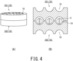
- FIG. 4 is a diagram illustrating a state where two conventional rubber molds 18 for CIP are stacked on top of each other. In FIG.
- reference sign 181 denotes an upper rubber mold
- reference sign 182 denotes a lower rubber mold
- reference sign 5 denotes a green compact being an object of CIP.
- the upper rubber mold 181 and the lower rubber mold 182 are examples of the rubber mold 18 for CIP.
- FIG. 4(A) is a perspective view of the upper and lower rubber molds 181 and 182 in a stacked state
- FIG. 4(B) is a lateral sectional view of the upper and lower rubber molds 181 and 182 in a stacked state.
- the green compact 5 is sealed between the upper rubber mold 181 and the lower rubber mold 182 (refer to FIG. 4(B) ).
- isostatic hydraulic pressure to the upper and lower rubber molds 181 and 182 which are stacked on top of each other, voids in the green compact 5 are evenly squashed from each direction and density inhomogeneity in the green compact 5 can be reduced.
- the hole sections 19 provided in the upper rubber mold 181 have approximately the same shape and a high symmetry of shape with respect to the hole sections 19 provided in the lower rubber mold 182.
- a diameter of an opening of the hole sections 19 of the upper and lower rubber molds 181 and 182 is denoted by a and a maximum depth of the hole sections 19 is denoted by b
- the hole sections 19 have a hemispherical shape with a ratio "a/b" of around 2.0.
- a ratio between a maximum depth and a depth near an edge was around 0.8 (Comparative examples 1 and 3 in Tables 1 and 2 to be described later).
- the rubber mold described in Patent Document 5 has a structure which combines a mortar and a pestle and a space obtained by a combination thereof has a spherical shape in a similar manner to the spaces observed in other related art. Therefore, even with the rubber mold described in Patent Document 5, when the rubber mold deviates in the horizontal direction, a torsional shear stress may occur in the green compact 5 particularly in a boundary section of engagement.
- Strength of the green compact 5 is often low and, due to rubbing between the upper and lower rubber molds 181 and 182 and shear stress on the green compact 5, defects such as partial chips and cracks occur in the green compact 5.
- a defect also occurs in a sintered compact that is generated after the CIP processing. For example, when bearing balls are processed from defective sintered compacts, only bearing balls with low reliability are obtained.
- the present invention has been made in order to solve such problems and an object thereof is to provide a rubber mold capable of reducing rubbing of a green compact which occurs between upper and lower rubber molds 181 and 182 and an occurrence of a torsional shear stress to the green compact when performing CIP processing.
- a rubber mold according to an embodiment is for CIP processing of a green compact with a plate shape.
- the rubber mold includes one or more approximately columnar hole sections are provided on at least one or more bottom surfaces. Further, when a diameter of an opening of the hole section is denoted by a and a maximum depth of the hole section is denoted by b, a/b ⁇ 2.0 is satisfied.
- a feature of the rubber mold for CIP according to the embodiment is that one or more approximately columnar hole sections are provided on at least one or more surfaces.
- FIG. 5 is a diagram showing a first example of the rubber mold for CIP according to the embodiment.
- FIG. 5(A) is a perspective view and
- FIG. 5(B) is a top view.
- FIG. 6 is a lateral sectional view showing a state where two of the first example of the rubber mold for CIP according to the embodiment have been stacked.
- reference sign 5 denotes a green compact being a CIP processing object prior to being subjected to CIP processing (hereinafter, simply described as a "green compact")
- reference sign 8 denotes a rubber mold for CIP (hereinafter, simply described as a “rubber mold”)
- reference sign 9 denotes an approximately columnar hole section (hereinafter, simply described as a "hole section")
- reference sign P denotes a groove section (engaging depression)
- reference sign Q denotes a projecting section (engaging projection).
- reference sign 81 denotes an upper rubber mold as an example of the rubber mold 8
- reference sign 82 denotes a lower rubber mold as an example of the rubber mold 8.
- a green compact obtained by CIP processing with respect to the green compact 5 is not limited to a spherical shape and may be a columnar shape (roller). Furthermore, a green compact obtained by CIP processing may be obtained by CIP processing with respect to the green compact 5 obtained by die molding or rolling granulation or may be solely obtained by CIP processing from filled powder.
- the fact that the green compact 5 may be obtained by die molding or rolling granulation means that the green compact 5 may or may not have the band-shaped section 7.
- CIP processing is more preferably performed with respect to the green compact 5 obtained by a method such as die molding or rolling granulation.
- the green compact 5 may have the band-shaped section 7 as shown in FIG.
- a shape of hole sections provided on one or more bottom surfaces is taken into consideration. Therefore, a side surface shape of the rubber mold 8 is not particularly limited. Consequently, the side surface of the rubber mold 8 may be completely absent of depressions or the like or a depression or a projection may be provided on the side surface as a guide.
- the depression is preferably not excessively large.
- a projection is preferably not excessively large.
- a space which is formed when the upper rubber mold 81 and the lower rubber mold 82 are engaged with each other and which includes the approximately columnar hole section 9 in which a green compact can be placed has an approximately columnar shape instead of a spherical shape.
- the rubber mold 8 is provided with one or more approximately columnar hole sections 9 on one or more bottom surfaces among two bottom surfaces which oppose each other.
- Reference sign a in FIG. 6 denotes a diameter of an opening of the hole section 9.
- the opening has one diameter if the hole section 9 is a right column, when the opening is not a precise circle but a shape similar to a precise circle, the diameter is a specific diameter (for example, a maximum diameter) among a plurality of diameters present in the opening. Therefore, for example, when the shape similar to a precise circle is an elliptical shape, reference sign a denotes a long axis diameter. Reference sign b denotes a maximum depth of the hole section 9.
- Reference sign c denotes a horizontal distance (a distance in a direction orthogonal to a depth direction) between adjacent hole sections 9 on a same rubber mold 8.
- the horizontal distance c is an average value of distances between side surfaces of a given hole section 9 and a hole section adjacent to the given hole section 9. Therefore, for example, when there are three hole sections 9 from first to third hole sections 9, an average value thereof is an average value of the three distances including a distance between the first hole section 9 and the second hole section 9, a distance between the second hole section 9 and the third hole section 9, and a distance between the third hole section 9 and the first hole section 9.
- Reference sign d denotes a vertical distance (a distance in the depth direction) between hole sections 9 when the upper and lower rubber molds 81 and 82 are stacked on top of each other.
- the vertical distance d is an average value between the bottom surfaces of the hole sections 9 of the upper rubber mold 81 and the openings of the hole sections 9 of the lower rubber mold 82 in a state where the upper and lower rubber molds 81 and 82 are stacked on top of each other.
- the rubber mold 8 is used for CIP processing.
- CIP processing includes so-called WET-CIP and so-called DRY-CIP.
- WET-CIP is a method of sealing powder or directly sealing a green compact with a bag or the like which has low deformation resistance and a certain level of strength or more and applying fluid pressure while preventing the powder or the green compact from coming into contact with a fluid.
- DRY-CIP is a pressurizing method which is performed via a rubber mold and which includes an object (like a stand) beneath the rubber mold 8 for supporting the rubber mold 8. Since the pressurization uses fluid pressure, molding due to isostatic pressure without directionality can be performed. Isostatic pressure enables an uneven density distribution in the green compact 5 to be suppressed.
- CIP is sometimes also referred to as cold isostatic press or rubber press. Particularly, among these methods, the rubber mold 8 produces favorable results when adopting DRY-CIP.
- the rubber mold 8 has one or more hole sections 9 on one bottom surface among opposing bottom surfaces.
- the hole section 9 has a substantially columnar shape.
- the green compact 5 has a spherical section 6 and the band-shaped section 7.
- the green compact 5 may be the spherical section 6 having a spherical shape without the band-shaped section 7.
- the hole section 9 further preferably has a size that enables the hole section 9 to comfortably accommodate the entire green compact 5. A position of the hole section 9 of the rubber mold 8 will be described.
- the hole section 9 is more preferably provided in plurality on one bottom surface among two opposing bottom surfaces.
- the ratio "a/b" is within a range of Expression (1) above, a void can be provided between the rubber mold 8 and the green compact 5 and an effect of reducing rubbing of the green compact 5 and a torsional shear stress to the green compact 5 can be expected.
- the ratio "a/b" more preferably satisfies Expression (2) below. The reason therefor is to maintain a yield of a ceramic ball material at a high level. a / b ⁇ 1.7
- the ratio "a/b” is small, such as less than 2.0 as indicated in Expression (1) described above, a gap is created between the green compact 5 and the hole section 9 and concentration of stress during conveyance of the upper and lower rubber molds 81 and 82 into a CIP processing apparatus or the like can be reduced.
- the ratio "a/b” so as to be less than 1.7 or equal to or less than 1.6 as indicated in Expressions (2) and (3) described above, in addition to improving yield, the effect of reducing stress concentration can be further increased.
- the ratio "a/b" when the ratio "a/b" is small, such as less than 0.4, since each stack needs to be unnecessarily thick in order to maintain strength per stack and there is a risk that the number of green compacts 5 that can be processed at the same time may decrease, such a small ratio "a/b” is not preferable. More preferably, the ratio "a/b" satisfies Expression (4) below. 0.6 ⁇ a / b ⁇ 1.6
- the ratio "a/b" satisfies Expression (5) below. 0.7 ⁇ a / b ⁇ 1.6
- the ratio "a/b” is preferably within a range indicated by Expression (6) below. Moreover, the ratio "a/b” is preferably within a range of Expression (7) below. The reason therefor is to maintain the yield of a ceramic ball material at a high level. 0.7 ⁇ a / b ⁇ 1.3 0.9 ⁇ a / b ⁇ 1.1
- FIGS. 7(A) and 7(B) show examples of a lateral sectional view in which a vicinity of one hole section 9 has been enlarged.
- a depth (maximum depth b) of the hole section 9 near a center of a bottom surface of the hole section 9 if a depth of the hole section 9 in the vicinity of an edge of the bottom surface of the hole section 9 is denoted by g, then a relationship of Expression (8) below preferably exists.
- FIG. 7(A) shows a case where the depth g of the hole section 9 in the vicinity of the edge of the bottom surface is equal to the maximum depth b.
- the depth of the hole section in the vicinity of the edge of the bottom surface in this case is no more and no less than the depth of the bottom surface and, for example, a case where an opening becomes damaged or a case of using a design in which the periphery of the opening is widened in order to facilitate retrieval do not correspond to the bottom surface and will not be taken into consideration as a depth.
- FIG. 7(C) shows a lateral sectional view in which a vicinity of one hole section 9 has been enlarged.
- a surface orthogonal to the depth direction of the hole section 9 is present in plurality in the depth direction in addition to the opening.
- a diameter of the opening among orthogonal surfaces that are present in plurality in the depth direction is denoted by a and a maximum diameter among surfaces which are parallel to the opening and which are present in plurality in the depth direction is denoted by h.
- the diameter a of the opening with respect to the maximum diameter h is preferably within a range of Expression (9) below. Note that in FIG.
- the size of the hole section 9 has been emphasized in order to facilitate understanding of a relationship between the diameter a of the opening and the maximum diameter h.
- the relationship between the diameter a of the opening and the maximum diameter h is not solely limited to the state shown in FIG. 7(C) and the relationship can be appropriately modified within a range of Expression (9) below. 0.9 ⁇ a / h ⁇ 1.0
- a range of a maximum diameter a with respect to a minimum diameter i is preferably within a range of Expression (10) below.
- a shape of the opening of the hole section 9 is expressed by exaggerating a difference between the maximum diameter a and the minimum diameter i for the sake of convenience.
- a shape of the hole section 9 having a depth and a diameter that satisfy Expression (8) above will be referred to as an approximately columnar shape.
- the shape more preferably also satisfies Expressions (9) and (10) described above.
- the diameter a and the maximum depth b of the opening of the hole section 9 are set large enough to accommodate the green compact 5. Giving the hole section 9 an approximately columnar shape enables pressure to the green compact 5 to be made isostatic. Furthermore, since the green compact 5 is not placed in a space created by stacking the upper and lower rubber molds 181 and 182 with hemispherical hole sections 19 as shown in FIGS. 3 and 4 , damage to the green compact 5 due to displacement of the upper and lower rubber molds 181 and 182 can be prevented.
- the rubber mold 8 has one or more hole sections 9. The hole section 9 becomes a location where the green compact 5 is to be accommodated. Due to the rubber mold 8 having a plurality of hole sections 9, a larger number of green compacts can be processed in one execution of CIP.
- the rubber mold 8 preferably has one or more engaging sections (a set of an engaging depression P and an engaging projection Q) for preventing surface disengagement.
- the engaging sections P and Q are more preferably provided so as to be approximately point-symmetric with respect to a center S of the bottom surface of the rubber mold 8 and continuous or intermittent along a circle or a polygon around the center S.
- the upper rubber mold 81 is more readily fitted into the lower rubber mold 82 without considering orientations even if the engaging sections P and Q are provided at a plurality of locations and the upper and lower rubber molds 81 and 82 are more readily engaged with each other.
- the engaging sections P and Q are more preferably arranged at one or more locations among locations closer to an edge T of the bottom surface of the rubber mold 8 (hereinafter, referred to as an "edge proximal section") than an intermediate line U between the center S and the edge T of the bottom surface of the rubber mold 8.
- an edge proximal section located closer to an edge T of the bottom surface of the rubber mold 8 (hereinafter, referred to as an "edge proximal section") than an intermediate line U between the center S and the edge T of the bottom surface of the rubber mold 8.
- the engaging sections P and Q are more preferably provided along the edge T among the edge proximal section of the bottom surface.
- the engaging sections P and Q are also arranged in a circle, and when the bottom surface of the rubber mold 8 is a polygon, the engaging sections P and Q are also arranged in a polygon.
- the engaging depression P and the engaging projection Q have an effect of preventing surface disengagement when the upper rubber mold 81 is stacked on top of the lower rubber mold 82.
- the engaging sections P and Q are assumed to be formed within a range of 50 [%] or more and 100 [%] or less of a length of a circumference of the edge T of the rubber mold 8.
- the locations where the engaging depression P is provided may correspond to 100 [%] of the length of a circumference of the edge T of the rubber mold 8 and the engaging projection Q may correspond to 50 [%] of the length of the circumference of the edge T of the rubber mold 8.
- lengths over which the engaging depression P and the engaging projection Q are to be provided may be the same or may differ from each other.
- the engaging projection Q may be longer, there is a risk when the engaging projection Q is longer that an excessively long engaging projection Q may prevent engagement from being realized. Therefore, when the engaging projection Q is longer, a difference in length is preferably small (for example, comparable to an error). In addition, when the lengths differ, the engaging projection Q is more preferably shorter than the engaging depression P.
- the engaging depression P may be provided on one bottom surface of the rubber mold 8 and the engaging projection Q may be provided on the other bottom surface or the engaging depression P and the engaging projection Q may be alternately provided on one bottom surface of the rubber mold 8 and the engaging depression P and the engaging projection Q may be alternately provided on the other bottom surface.
- the engaging sections P and Q may be continuously or intermittently provided, more preferably, there is only a small deviation in locations where the engaging sections P and Q are provided in the edge proximal section of the bottom surfaces. When there is only a small deviation, an effect of providing the engaging sections P and Q is more readily produced. On the other hand, when the deviation is large, depending on an orientation of a force applied when the engaging sections P and Q are provided, there is a risk that the engaging sections P and Q become more readily disengaged.
- the engaging sections P and Q arranged in the edge proximal section of the bottom surfaces of the rubber mold 8 are continuously provided. Providing the engaging sections P and Q along an entire circumference of the edge proximal section of the bottom surfaces of the rubber mold 8 enables the upper and lower rubber molds 81 and 82 to be readily positioned.
- a thickness of the provided engaging sections P and Q is preferably 3 [%] or more of the diameter of the rubber mold 8 and more preferably 7 [%] or less. When the thickness (wall thickness) of the engaging sections P and Q is thin, such as less than 3 [%] of the diameter of the rubber mold 8, there is a risk that sufficient durability may not be obtained.
- the wall thickness may differ in each of the engaging depression P and the engaging projection Q.
- a difference between the wall thickness of the engaging depression P and the wall thickness of the engaging projection Q is preferably 0 [%] or more and 3 [%] or less and more preferably [%] or more and 2 [%] or less of the diameter of the rubber mold 8.
- the engaging depression P is more preferably thicker than the engaging projection Q.
- the engaging depression P is provided on the bottom surface provided with the hole section 9 among the two opposing bottom surfaces and the engaging projection Q is provided on the other bottom surface in FIGS. 5 and 6
- the engaging depression P and the engaging projection Q may be reversed.
- the engaging projection Q may be provided on the bottom surface provided with the hole section 9 and the engaging depression P may be provided on the other bottom surface.
- the engaging sections P and Q need only be provided in the edge proximal section of the bottom surfaces of the rubber mold 8 and are not limited to a case of being provided along the edge T as shown in FIGS. 5 and 6 .
- the engaging depression P may be arranged at a location separated from the edge T so that a length j of an outer circumferential flat section with respect to the diameter of the rubber mold 8 is 2 [%] or less.
- the engaging depression P is more preferably arranged at a location separated from the edge T so that the length j of the outer circumferential flat section with respect to the diameter of the rubber mold 8 is 1 [%] or less.
- the length j of the outer circumferential flat section is more preferably within 1 [cm].
- the thickness of the engaging sections P and Q of the rubber mold 8 will be described.
- the thickness of the engaging sections P and Q is preferably 3 [%] or more and 7 [%] or less of the diameter of the rubber mold 8.
- the thickness of the engaging sections P and Q is thin, such as less than 3 [%] of the diameter of the rubber mold 8, there is a risk that sufficient durability of the engaging sections P and Q may not be obtained.
- the thickness of the engaging sections P and Q is large, such as more than 7 [%] of the diameter of the rubber mold 8, since the number of the hole sections 9 decreases, the number of green compacts 5 that can be subjected to one execution of CIP processing decreases, creating a risk of a drop in mass productivity.
- a difference between a thinnest location and a thickest location is preferably small.
- a volume V1 occupied by a space of the engaging depression P may be larger or smaller than a volume V2 occupied by the engaging projection Q, a difference between the volumes is preferably not excessively large.
- the volume V2 occupied by the engaging projection Q with respect to the volume V1 occupied by the space of the engaging depression P (ratio "V2/V1") satisfies Expression (11) below. More preferably, the ratio "V2/V1" satisfies Expression (12) below.
- a depth e of the engaging depression P is 1.5 [mm] or more and a height f of the engaging projection Q is 1.5 [mm] or more.
- the depth e of the engaging depression P and the height f of the engaging projection Q preferably satisfy Expressions (13) and (14) below.
- the rubber mold 8 does not have a depression of which a depth is 1.5 [mm] or more and a projection of which a height is 1.5 [mm] or more other than the engaging sections P and Q on the bottom surfaces.
- the engaging depression P and the engaging projection Q for positioning when stacking the upper and lower rubber molds 81 and 82 are not formed outside of the outer circumferential section.
- positioning when stacking the upper and lower rubber molds 81 and 82 is characteristically performed by fitting the engaging depression P of the lower rubber mold 82 and the engaging projection Q of the upper rubber mold 81 to each other.
- the hole sections 9 for accommodating the green compacts 5 are not counted as the engaging depression P.
- the hole section 9 is provided in plurality, there may be some hole sections 9 which do not accommodate green compacts 5.
- the engaging depression P of the upper rubber mold 81 and the engaging projection Q of the lower rubber mold 82 are fitted to each other. Therefore, the hole sections 9 and the engaging depression P can be distinguished from each other.
- providing depressions of which a depth is less than 1.5 [mm] in the rubber mold 8 enables a weight of the rubber mold 8 to be reduced. From the perspective of equalizing an amount of deformation of the rubber mold 8, more preferably, there is no depression of which a depth is less than 1.5 [mm] and no projection of which a height is less than 1.5 [mm] other than the engaging depression P and the engaging projection Q.
- the diameter a refers to a diameter in the opening of the hole section 9 (a maximum diameter when the opening is not a precise circle).
- the maximum depth b of the hole section 9 refers to a maximum depth among depths of the hole section 9.
- a boundary between the side surface and the bottom surfaces of the hole section 9 may be a right angle (refer to FIG. 7(A) )
- the boundary between the side surface and the bottom surfaces may be chamfered (refer to FIG.
- the diameter a of the opening of the hole section 9 with respect to a maximum dimension L of the green compact 5 is preferably within a range of 1.01 or more and 1.82 or less and the maximum depth b with respect to the maximum dimension L of the green compact 5 (ratio "b/L”) is preferably within a range of 1.01 or more and 1.82 or less.
- the ratio "a/L” and the ratio "b/L” are preferably respectively within ranges of Expressions (15) and (16) below. 1.01 ⁇ a / L ⁇ 1.82 1.01 ⁇ b / L ⁇ 1.82
- the hole section 9 becomes excessively large.
- a torsional shear stress due to the rubber mold 8 may be created on the green compact 5.
- a torsional shear stress is a stress that reacts when the rubber mold 8 is twisted so as to stop the twisting.
- isostatic pressure is not applied to the green compact 5.
- one hole section 9 becomes filled by a plurality of green compacts 5.
- the range of the ratio "a/L” indicated in Expression (15) above is more preferably within a range of 1.03 or more and 1.35 or less and the range of the ratio "b/L” indicated in Expression (16) above is more preferably within a range of 1.03 or more and 1.35 or less.
- the range of the ratio "a/L” is more preferably within a range of Expression (17) below and the range of the ratio "b/L” is more preferably within a range of Expression (18) below. 1.03 ⁇ a / L ⁇ 1 .35 1.03 ⁇ b / L ⁇ 1.35
- isostatic hydraulic pressure can be applied to the green compact 5.
- a reduction of voids in the green compact 5 and suppression of density inhomogeneity can be performed.
- a method of measuring the diameter a, the maximum depth b, and the horizontal distance c of the opening of the hole section 9 will now be described. It is assumed that a noncontact measurement method is to be used for the measurements. This is because, with contact length measurement using a Vernier caliper, a depth meter, or the like, values vary due to deformation of the rubber mold 8 upon contact.
- An optical three-dimensional shape measuring apparatus is to be used for shape measurement.
- VR-5000 manufactured by KEYENCE Corporation is to be used as the three-dimensional shape measuring apparatus and the measurement is to be performed using analysis software of the apparatus.
- a measurement apparatus need only be functionally equivalent to the apparatus described above.
- the vertical distance d of the hole sections 9 when stacking the rubber molds 8 is to be measured using a cross section which passes centers of the hole sections 9 of the rubber molds 8.
- a method of measurement using the three-dimensional shape measuring apparatus described above with respect to the cross section is preferable.
- a vertical distance between each hole section 9 and a nearest hole section 9 is measured and an average value of a plurality of vertical distances corresponding to the plurality of hole sections 9 is denoted by d.
- measurements may be performed using a micrometer with a shape that does not cause the shape of the rubber mold 8 to change or a depth meter.
- the diameter a, the maximum depth b, the horizontal distance c, and the vertical distance d of the opening are average values.
- the ratio "a/b” satisfies any of Expressions (1) to (7) above and the ratio "a/L” or “b/L” satisfies Expressions (15) and (16) above or Expressions (17) or (18) above.
- the ratio "a/b” satisfies any of Expressions (1) to (7) above and the ratio "a/L” or “b/L” satisfies Expressions (15) and (16) above or Expressions (17) or (18) above.
- the diameter a (ratio "a/c") and the maximum depth b (ratio "b/c") of the opening of the hole section 9 are preferably 4 or less.
- the ratio "a/c” and the ratio "b/c” are preferably within a range of Expressions (19) and (20) below.
- the ratio "a/c” and the ratio "b/c” respectively being within the ranges of Expressions (19) and (20) above indicate that the secured horizontal distance c is sufficient with respect to the diameter a of the opening of adjacent hole sections 9. In a similar manner, it is indicated that the secured horizontal distance c is sufficient with respect to the maximum depth b.
- the ratio "a/c” and the ratio "b/c” exceeding 4 indicate that the distance between adjacent hole sections 9 is near. When the distance between adjacent hole sections 9 is near, there is a possibility that the rubber mold 8 is unable to sufficiently deform. When deformation of the rubber mold 8 is insufficient, there is a possibility that isotropy of pressure applied to the green compact 5 may break down and prevent density from being homogenized. Note that the lower limit values of the ratio "a/c” and the ratio "b/c” are not particularly limited and need only be within the ranges of expressions (19) and (20) above.
- the range of the ratio "a/c” indicated in Expression (19) above is more preferably within a range of 0.1 or more and 4.0 or less and the range of the ratio "b/c” indicated in Expression (20) above is more preferably within a range of 0.1 or more and 4.0 or less.
- the range of the ratio "a/c” is more preferably within a range of Expression (21) below and the range of the ratio "b/c” is more preferably within a range of Expression (22) below.
- the ratio "a/c” and the ratio “b/c” are more preferably both 0.2 or more and even more preferably both 0.3 or more.
- the ratios are preferably controlled to 0.2 or more or 0.3 or more.
- the vertical distance d with respect to the horizontal distance c is preferably 0.9 or more.
- the ratio "d/c” is preferably within a range of Expression (23) below.
- isostatic pressure can be applied to the green compact 5 when stacking the upper and lower rubber molds 81 and 82 and performing CIP processing.
- the ratio "d/c" being smaller than 0.9 means that the vertical distance d is short with respect to the horizontal distance c.
- a difference in amounts of deformation of the upper and lower rubber molds 81 and 82 between a horizontal direction and a vertical direction increases.
- isotropy of pressure applied to the green compact 5 may break down.
- the ratio "d/c” is more preferably 200 or less.
- the range of the ratio "d/c” is more preferably a range of Expression (24) below. 0.9 ⁇ d / c ⁇ 200
- the ratio "d/c" is preferably 100 or less and more preferably controlled to 50 or less. Since exercising control as described above enables a thickness per stack to be controlled and the number of green compacts 5 subjected to CIP processing per unit volume to be increased, CIP processing can be performed in an efficient manner.
- the rubber mold 8 preferably has a plate shape such as an approximately precise disc shape.
- An approximately precise disc shape indicates a right column shape or an elliptical column shape of which a height between two opposing bottom surfaces is relatively low.
- the plate-shaped rubber mold 8 is not limited to a disc shape and may be a polygonal shape or the like. When the rubber mold 8 has a polygonal shape, the polygon is preferably a pentagon or more.
- the rubber mold 8 is provided with engaging sections P and Q in an outer circumferential section thereof. When the rubber mold 8 has a disc shape, positioning is more readily performed when stacking the plurality of rubber molds 8 on top of each other.
- the upper and lower rubber molds 81 and 82 are directionless and can be readily stacked. Furthermore, when transporting the rubber molds 8 having been stacked in multiple stacks, the rubber molds 8 can be prevented from collapsing.
- the number of stacks of the rubber mold 8 is preferably two stacks or more. Stacking a plurality of rubber molds 8 enables a larger number of green compacts 5 to be subjected to CIP processing at the same time.
- the number of stacks of the rubber mold 8 is not particularly limited, the number of stacks is preferably 100 or less.
- the number of stacks is more preferably 2 stacks or more and 40 stacks or less. More preferably, the number of stacks is 2 stacks or more and 25 stacks or less.
- the number of stacks is more preferably 3 stacks or more and 20 stacks or less.
- the heights of the plurality of rubber molds 8 preferably have a small error.
- the error is preferably 10% or lower. This is because there is a risk of collapsing during transportation when the error of heights of the plurality of rubber molds 8 is large.
- areas of stacking surfaces of the plurality of rubber molds 8 also have a small error. This is because of a risk that uniformly applying pressure during CIP processing may become difficult when the error among areas of stacking surfaces in the plurality of rubber molds 8 is large.
- a depression, a projection, or the like may be provided on the side surface or the lower bottom surface (the surface not provided with a hole section) of the rubber mold 8 as a guide or for the purpose of reducing weight or the like.
- the shape of the side surface or the lower bottom surface of the rubber mold 8 is not particularly limited.
- Shore hardness Hs of rubber of the rubber mold 8 is preferably within a range of 30 or more and 50 or less. As described earlier, isostatic pressure is applied to the rubber mold 8 accommodating the green compact 5. When the Shore hardness Hs is within a range of 30 or more and 50 or less, an amount of deformation can be homogenized. Therefore, a deformation ability that enables a surface of the green compact and the rubber mold to come into contact with each other in a uniform manner can be provided. In addition, durability of the rubber mold is also favorable. Note that the Shore hardness Hs is measured in conformance with JIS-Z-2246 (2000).
- the green compact 5 may have a spherical shape, a columnar shape, a plate shape, or the like.
- the green compact 5 preferably has a spherical shape as shown in FIG. 2 .
- the spherical shape has the spherical section 6 and the band-shaped section 7.
- isostatic pressure can be applied to the green compact 5.
- an effect of isostatic pressure is more readily produced when the green compact 5 has a ball shape.
- the diameter a of the opening of the hole section 9 is set in accordance with the maximum dimension L of the green compact 5 according to Expression (15) or (17) above and the maximum depth b is set in accordance with the maximum dimension L of the green compact 5 according to Expression (16) or (18) above.
- the horizontal distance c is set in accordance with the set diameter a and the maximum depth b of the opening according to Expressions (19) and (20) above or Expressions (21) and (22) above.
- the vertical distance d is set in accordance with the set horizontal distance c according to Expression (23) or (24) above.
- the green compact 5 preferably contains one or more of the group consisting of aluminum oxide, silicon nitride, boron nitride, zirconium oxide, silicon carbide, and aluminum nitride as a main component (50 [mass %] or more) and more preferably contains 85 [mass %] or more of one or more of the group consisting of aluminum oxide, silicon nitride, boron nitride, zirconium oxide, silicon carbide, and aluminum nitride.
- the green compact 5 preferably contains 85 [mass %] or more of silicon nitride. After CIP, the green compact 5 goes through a sintering step and becomes a ceramic sintered compact.
- the ceramic sintered compact When the green compact 5 has a ball shape, the ceramic sintered compact also acquires a ball shape.
- a ceramic sintered compact with a ball shape is used as a bearing ball.
- the materials described above are used in a ceramic bearing ball.
- a silicon nitride sintered compact has superior abrasion resistance and is effective as a bearing ball.
- the green compact 5 containing 85 [mass %] or more of one or two or more of the group consisting of aluminum oxide, silicon nitride, boron nitride, zirconium oxide, silicon carbide, and aluminum nitride means that the obtained ceramic sintered compact also contains 85 [mass %] or more of one or two or more of the group consisting of aluminum oxide, silicon nitride, boron nitride, zirconium oxide, silicon carbide, and aluminum nitride.
- the green compact 5 may contain 15 [mass %] or less of a sintering aid.
- the green compact 5 containing 85 [mass %] or more of any one of the group consisting of aluminum oxide, silicon nitride, boron nitride, and zirconium oxide means that the obtained ceramic sintered compact also contains 85 [mass %] or more of any one of the group consisting of aluminum oxide, silicon nitride, boron nitride, and zirconium oxide.
- the green compact 5 may contain 15 [mass %] or less of a sintering aid.
- an aluminum oxide sintered compact or a zirconium oxide sintered compact has a Vickers hardness of around 1200 or more and 1700 or less.
- a toughness value is low at around 3 [MPa ⁇ m 1/2 ] or more and 6 [MPa ⁇ m 1/2 ] or less.
- a silicon nitride sintered compact has a higher Vickers hardness of around 1400 or more and 1800 or less.
- a toughness value is higher at around 5 [MPa ⁇ m 1/2 ] or more and 10 [MPa ⁇ m 1/2 ] or less.
- a silicon nitride sintered compact has both a high toughness value and a high Vickers hardness and, therefore, has superior abrasion resistance.
- Beta-silicon nitride crystal particles have an elongated shape and a high toughness value is achieved by complicated entanglement of the elongated crystal particles.
- the spherical ceramic sintered compact after the sintering step is called a ceramic ball material.
- the ceramic ball material is a spherical body with a band-shaped section attributable to the band-shaped section 7 (illustrated in FIG. 2 ) of the green compact 5.
- the ceramic ball material subjected to polishing processing and made into a spherical body is called a bearing ball.
- the rubber mold 8 is suitable for applying isostatic pressure to the green compact 5.
- the rubber mold 8 is suitable for subjecting the green compact 5 to CIP processing.
- bearing balls are available in various diameters within a range of 1 [mm] or more and 50 [mm] or less. The rubber mold 8 can be applied to green compacts 5 of various sizes.
- the method of manufacturing the ceramic ball material according to the embodiment is a method of using the rubber mold 8 described above.
- a green compact is a spherical ceramic green compact and the method includes a step of subjecting the ceramic green compact to CIP processing using the rubber mold 8 and a step of sintering the green compact having been subjected to CIP processing.
- the step of subjecting the green compact 5 to CIP processing is preferably performed by stacking a plurality of rubber molds 8.
- the ratio "d/c" of the vertical distance d with respect to the horizontal distance c of the stacked rubber molds 8 is preferably within the range of Expression (23) or (24) above.
- a method of preparing the green compact 5 will be described using silicon nitride as an example.
- silicon nitride any one or more of the group consisting of aluminum oxide, boron nitride, and zirconium oxide is to be used as a main component (50 mass % or more)
- the term "silicon nitride" is to be replaced with any one or more of aluminum oxide, boron nitride, and zirconium oxide.
- a molding method is not limited thereto.
- a rolling granulation method may be adopted as the molding method.
- uniaxial pressing will be cited as an example of obtaining the green compact 5 in Examples of the present invention, a molding method is not limited thereto. Therefore, for example, a green compact obtained by a rolling granulation method may be used.
- a sintering aid an additive, a solvent, a binder, and the like are added to silicon nitride to be a raw material, and after mixing and crushing, granulation is performed by a spray drier. Granulated powder of raw material powder is prepared by this step.
- the silicon nitride powder is preferably 85 [mass %] or more.
- the additive is a plasticizer or the like.
- the solvent is water or an organic solvent. Examples of the organic solvent include alcohol, ketone, and benzene.
- the binder is an organic substance.
- an additive amount of the binder is 3 parts by mass or more and 20 parts by mass or less. Adjusting the binder amount enables a shape retention force and density uniformity of the green compact during uniaxial pressing and CIP to be adjusted. Furthermore, using granulated powder enables the silicon nitride powder and the sintering aid powder to be uniformly mixed.
- uniaxial pressing is performed using the granulated powder.
- the uniaxial pressing include a die molding method using the upper die 1 and the lower die 2 shown in FIG. 1 .
- a shape of the green compact can be adjusted according to shapes of the dies.
- the green compact 5 with a spherical shape can be obtained by respectively making insides of the upper die 1 and the lower die 2 a hemispherical shape.
- the green compact with a roller shape (approximately columnar shape) can be obtained by respectively making insides of the upper die 1 and the lower die 2 an approximately columnar shape.
- the green compact 5 obtained by the uniaxial pressing exhibits a spherical shape (illustrated in FIG. 2 ) or a columnar shape having the spherical section 6 and the band-shaped section 7.
- the green compact obtained by uniaxial pressing is the green compact 5 being an object of CIP.
- the rubber mold 8 is used when performing CIP processing.
- the green compact 5 is placed inside the hole section 9 of the rubber mold 8.
- Providing a plurality of the hole sections 9 in the rubber mold 8 enables a larger number of green compacts 5 to be processed.
- all of the hole sections 9 are preferably filled with the green compacts 5. While a part of the hole sections 9 need not be filled with the green compacts 5, filling all of the hole sections 9 with the green compacts 5 more readily enables isostatic pressure to be homogenized.
- the hole section 9 is preferably filled with the green compact 5 so that the band-shaped section 7 of the green compact 5 faces the depth direction of the hole section 9.
- an orientation of the band-shaped section 7 is optional. Giving the opening the diameter a and the maximum depth b suitable for the maximum dimension L of the green compact 5 enables the orientation of the band-shaped section 7 to be optional. Therefore, the rubber mold 8 can be described a rubber mold suitable for CIP processing of the green compact 5 having the band-shaped section 7.
- the green compact 5 is molded using granulated powder. Applying isostatic pressure to the green compact 5 by CIP processing crushes the granulated powder and suppresses variability in density. Using granulated powder when molding the green compact 5 enables silicon nitride powder and sintering aid powder to be uniformly dispersed and enables density variability to be suppressed. When pressure applied to the green compact 5 during CIP processing is inhomogeneous, granulated powder remains without being crushed. Portions that remain without being crushed cause density variability.
- pressure of CIP molding is preferably higher than pressure of pressing in uniaxial pressing.
- a condition of CIP processing is preferably within a pressure range of 30 [MPa] or higher and 300 [MPa] or lower. When the pressure is within this range, density variability of the green compact after the CIP processing can be reduced. In particular, this is effective when using a rubber mold with a Shore hardness Hs of 30 or more and 50 or less. Pressure may possibly be insufficient when CIP pressure is less than 30 MPa. In addition, durability of the rubber mold 8 may decline when pressure is high, such as higher than 300 [MPa].
- the degreasing step is a step of heating at a decomposition temperature of organic components such as the binder or at a higher temperature to blast away the organic components.
- the degreasing step may be performed in a nitrogen atmosphere or an ambient atmosphere. A degreased body can be obtained through the degreasing step.
- a sintering step of sintering the degreased body is performed.
- the sintering step is preferably at 1700 degrees Celsius or higher and 2000 degrees Celsius or lower.
- the sintering step is preferably performed in a nitrogen atmosphere.
- HIP (hot isostatic pressing) processing may also be performed with respect to the sintered body obtained by the sintering process.
- a ceramic ball material can be obtained.
- the ceramic ball material is to be a ceramic sintered compact with a theoretical density of 98 [%] or higher.
- a ceramic ball can be manufactured by subjecting the ceramic ball material to polishing processing.
- polishing processing include surface plate processing.
- the ceramic ball material is inserted between surface plates provided vertically so as to be parallel to each other. Due to motion of the polishing surface plates, the ceramic ball material can be processed to a pearl shape.
- Surface roughness of bearing balls is defined in ASFM F2094.
- grades conforming to ASTM F2094, ISO 26602, or JIS R1669 are adopted. Polishing is performed to a surface roughness Ra conforming to the grades. At higher grades, mirror finishing to a surface roughness Ra of 0.01 [ ⁇ m] or less may be performed.
- the green compact 5 of Example 1 and Comparative example 1 is an aluminum oxide green compact
- the green compact 5 of Examples 2 and 3, 5 to 9, and 12 to 14 and Comparative example 3 is a silicon nitride green compact
- the green compact of Examples 4, 10, and 11 and Comparative example 2 is a zirconium oxide green compact.
- the aluminum oxide green compact of Example 1 and Comparative example 1 contains 85 [mass %] or more of aluminum oxide.
- the silicon nitride green compact of Examples 2 and 3, 5 to 9, and 12 to 14 and Comparative example 3 contains 85 [mass %] or more of silicon nitride.
- the zirconium oxide green compact of Examples 4, 10, and 11 and Comparative example 2 contains 85 [mass %] or more of zirconium oxide.
- press molding was performed using granulated powder.
- Press molding is performing by die molding using upper and lower dies in the press molding apparatus shown in FIG. 1 .
- the press molding using upper and lower dies is uniaxial pressing.
- the dies are for making a spherical green compact. Accordingly, the green compact 5 being an object of CIP was fabricated. Furthermore, as shown in FIG. 2 , the green compact 5 has the spherical section 6 and the band-shaped section 7.
- the rubber mold 8 with a Shore hardness Hs of 30 or more and 50 or less was used for the CIP processing.
- a plurality of hole sections 9 were provided on one of the bottom surfaces of the rubber mold 8. The diameter a and the maximum depth b of the opening of the hole section 9 with respect to the maximum dimension L of the green compact 5 were respectively set in a relationship with the maximum dimension L of the green compact 5 within the range of Expression (15) or (16) above.
- the hole section 9 of the rubber mold 8 was filled with the green compact 5 so that the band-shaped section 7 of the green compact 5 became vertical.
- the rubber mold 8 was stacked in plurality.
- the green compact 5 was subjected to CIP processing in this state. Pressure of CIP was set within a range of 30 [MPa] or more and 300 [MPa] or less and hydrostatic pressure higher than the pressure of uniaxial pressing was applied. According to this step, the green compact after CIP processing was fabricated.
- a degreasing step of the green compact after CIP processing was performed.
- a sintering step was performed.
- the sintering step was performed at 1800 degrees Celsius in a nitrogen atmosphere under atmospheric pressure.
- HIP processing was performed at a temperature of 1700 degrees Celsius or more and 1900 degrees Celsius or less in a nitrogen atmosphere under pressure of 50 [MPa] or more and 200 [MPa] or less.
- a ceramic ball material made of a ceramic sintered compact according to Examples was manufactured.
- a ceramic ball material was fabricated by appropriately changing shapes of the rubber mold used in the CIP processing after the press molding step from the shape of the rubber mold 8.
- Features of the rubber mold 8 according to Examples 1 to 14 and features of the rubber mold according to Comparative examples 1 and 2 are as shown in Table 1.
- a "shape of hole section" described in Table 1 will now be described.
- An approximately columnar rubber mold satisfying any of Expressions (8) to (10) is described as "column".
- a presence or absence of engaging sections in an edge proximal section is described as a presence or absence of an engaging depression and a presence or absence of an engaging projection.
- a presence or absence of a depression or a projection other than the engaging depression and the engaging projection is a description of a presence or absence of a depression or a projection of which a height or a depth is 1.5 [mm] or more other than the engaging sections in the edge proximal section.
- a visual inspection of a sintered compact prior to polishing was performed using ceramic ball materials manufactured from the green compacts 5 according to Examples 1 to 14 and Comparative examples 1 to 3.
- the number of sintered compacts for 1.34 [mm] bearings to be inspected was 10,000.
- the number of sintered compacts for 5/16 inch bearings to be inspected was 1000.
- a green compact with a chip or a crack with a width of 0.7 [mm] or more or a depth of 0.5 [mm] or more on a surface thereof was defined as a defect.
- Examples 1, 2, 6, 11, 12, and 13 and Comparative example 1 shown in Tables 1 and 2 above are ceramic ball materials to become a 1.34 [mm] ceramic ball after polishing processing.
- Examples 3 to 5, 7 to 10, and 14 and Comparative example 2 are ceramic ball materials to become a 5/16 inch (7.9375 [mm]) ceramic ball. Both ceramic balls can be used as a bearing ball.
- Example 5 since the Shore hardness Hs of the rubber mold 8 was 20 and outside of a preferable range (30 or more and 50 or less) and the value of the ratio "a/b" of the rubber mold 8 was outside of a most preferable range (Expression (7) above), yield was “good”. Furthermore, in Examples 11 to 14, while the value of the ratio "a/b” satisfied Expression (1) above, since the value of the ratio "a/b” was outside of a preferable range (any of Expressions (2) to (7) above), yield was “good".
- the hole section 9 in an approximately columnar shape and adjusting the ratio "a/b" to less than 2.0, rubbing of a green compact which occurs between upper and lower rubber molds and an occurrence of a torsional shear stress to the green compact when performing CIP processing can be reduced.
- a yield of a ceramic ball material can be maintained at a high level.
Landscapes
- Engineering & Computer Science (AREA)
- Chemical & Material Sciences (AREA)
- Ceramic Engineering (AREA)
- Manufacturing & Machinery (AREA)
- Structural Engineering (AREA)
- Materials Engineering (AREA)
- Organic Chemistry (AREA)
- Mechanical Engineering (AREA)
- Physics & Mathematics (AREA)
- Fluid Mechanics (AREA)
- General Engineering & Computer Science (AREA)
- Composite Materials (AREA)
- Inorganic Chemistry (AREA)
- Moulds For Moulding Plastics Or The Like (AREA)
Abstract
Description
- An embodiment described below relates to a rubber mold for cold isostatic pressing, a method of manufacturing a ceramic ball material, and a method of manufacturing a ceramic ball.
- Various ceramic materials have properties such as high hardness, insulation properties, and abrasion resistance and, in particular, fine ceramics of which purity has been enhanced and a particle size has been homogenized exhibit properties that lead to use in various fields such as capacitors, actuator materials, and refractory materials. Among such fine ceramics, bearing balls are products that take advantage of abrasion resistance and insulation properties. Materials such as aluminum oxide, silicon nitride, and zirconium oxide are used in bearing balls. For example,
Japanese Patent Laid-Open No. H6-48813 Japanese Patent No. 2764589 Japanese Patent Laid-Open No. S60-18620 Patent Document 5 are also known, a hole section is not an approximately columnar shape (with a value of "depth of end/maximum depth" of around 0.8) and a space capable of accommodating a green compact (or powder compact) obtained when an upper rubber mold and a lower rubber mold being the mortar and the pestle are engaged with each other has a spherical shape as in related art. - In a process of manufacturing these materials for bearings, a method of sintering a green compact is used. In addition, as a molding method, a press molding apparatus using a die is used. Generally, as shown in
FIG. 1 , the press molding apparatus includes an upper die 1 and alower die 2 and adopts a system in which a powder is filled between the upper die 1 and thelower die 2 and pressure is applied. A binder or the like has been added as necessary to the powder to be filled. During press molding, the press molding must be performed while providing a gap between a tip portion 3 of the upper die 1 and atip portion 4 of thelower die 2 in order to protect the dies. To this end, a spherical section 6 and a band-shaped section 7 are formed in a green compact 5 (illustrated inFIG. 2 ). - For example,
Japanese Patent No. 4761613 FIG. 2 . InFIG. 2 ,reference sign 5 denotes a green compact, reference sign 6 denotes a spherical section,reference sign 7 denotes a band-shaped section, and reference sign L denotes a maximum dimension (or a maximum diameter) of the spherical section 6. The band-shaped section 7 has a width W and a height H with respect to a surface of the spherical section 6. In addition, given that the green compact is formed by uniaxial pressing, a force applied to the powder is in one direction and it is difficult to completely eliminate an internal void. When there is a residual void of a certain size or more in the green compact, reliability of a bearing ball after finish machining drops significantly. Furthermore, since density inhomogeneity in the green compact increases, contraction irregularities during a sintering step are more likely to occur and products are more prone to defects such as distortions and cracks. As a method of preventing a residual void of a green compact, performing cold isostatic pressing (CIP) processing with respect to the green compact 5 is effective. The CIP processing is a method of applying isostatic hydraulic pressure to the green compact 5 from a periphery thereof in a state where the periphery of the green compact 5 is sealed by rubber, film, or the like. -
- Patent Document 1:
Japanese Patent Laid-Open No. H6-48813 - Patent Document 2:
Japanese Patent No. 2764589 - Patent Document 3:
Japanese Patent Laid-Open No. S60-18620 - Patent Document 4:
Japanese Patent No. 4761613 - Patent Document 5:
Japanese Patent Laid-Open No. H10-6093 -
FIG. 3 illustrates a conventional rubber mold for CIP. InFIG. 3 ,reference sign 18 denotes the rubber mold for CIP. In addition,FIG. 3(A) is a perspective view of therubber mold 18 for CIP, andFIG. 3(B) is a lateral sectional view of therubber mold 18 for CIP. - In this case, the
rubber mold 18 for CIP for processing the green compact 5 (illustrated inFIG. 2 ) is a forming mold used when performing CIP forming. Therubber mold 18 for CIP has a plate shape. In this case, having a plate shape means having a certain thickness (height). In theconventional rubber mold 18 for CIP, a plurality ofhemispherical hole sections 19 are respectively provided on two opposing bottom surfaces (in the diagram, an upper surface and a lower surface excluding a side surface).FIG. 4 is a diagram illustrating a state where twoconventional rubber molds 18 for CIP are stacked on top of each other. InFIG. 4 ,reference sign 181 denotes an upper rubber mold,reference sign 182 denotes a lower rubber mold, andreference sign 5 denotes a green compact being an object of CIP. Theupper rubber mold 181 and thelower rubber mold 182 are examples of therubber mold 18 for CIP. In addition,FIG. 4(A) is a perspective view of the upper andlower rubber molds FIG. 4(B) is a lateral sectional view of the upper andlower rubber molds - In related art, by placing the
green compact 5 in thehole sections 19 of thelower rubber mold 182 and stacking theupper rubber mold 181 and thelower rubber mold 182 so that thehole sections 19 of theupper rubber mold 181 are aligned with opposinghole sections 19 of thelower rubber mold 182, thegreen compact 5 is sealed between theupper rubber mold 181 and the lower rubber mold 182 (refer toFIG. 4(B) ). By applying isostatic hydraulic pressure to the upper andlower rubber molds green compact 5 are evenly squashed from each direction and density inhomogeneity in thegreen compact 5 can be reduced. - In addition, while a mold with a structure combining a mortar and a pestle as described in
Patent Document 5 are also known, a space into which a green compact can be placed when an upper rubber mold and a lower rubber mold being the mortar and the pestle are engaged with each other has a spherical shape as in related art. - On the other hand, the
hole sections 19 provided in theupper rubber mold 181 have approximately the same shape and a high symmetry of shape with respect to thehole sections 19 provided in thelower rubber mold 182. In addition, when a diameter of an opening of thehole sections 19 of the upper andlower rubber molds hole sections 19 is denoted by b, thehole sections 19 have a hemispherical shape with a ratio "a/b" of around 2.0. Furthermore, in rubber molds of which the ratio "a/b" is around 1.0 among the rubber molds described in related art, a ratio between a maximum depth and a depth near an edge was around 0.8 (Comparative examples 1 and 3 in Tables 1 and 2 to be described later). Therefore, according to the conventional method of providing hemispherical hole sections, when the mgreen compact 5 is placed in thehole sections 19 of a bottom surface on an upper side of thelower rubber mold 182, an upper hemisphere of thegreen compact 5 protrudes from the bottom surface. When installing theupper rubber mold 181 on thelower rubber mold 182 in which thegreen compact 5 protrudes from the upper-side bottom surface, correctly aligning positions is difficult and thegreen compact 5 may rub against the upper andlower rubber molds - Furthermore, even if the
upper rubber mold 181 is successfully installed on thelower rubber mold 182 without any rubbing, when the upper andlower rubber molds green compact 5. In addition, the rubber mold described inPatent Document 5 has a structure which combines a mortar and a pestle and a space obtained by a combination thereof has a spherical shape in a similar manner to the spaces observed in other related art. Therefore, even with the rubber mold described inPatent Document 5, when the rubber mold deviates in the horizontal direction, a torsional shear stress may occur in thegreen compact 5 particularly in a boundary section of engagement. - Strength of the
green compact 5 is often low and, due to rubbing between the upper andlower rubber molds green compact 5, defects such as partial chips and cracks occur in thegreen compact 5. When there is a defect in thegreen compact 5, a defect also occurs in a sintered compact that is generated after the CIP processing. For example, when bearing balls are processed from defective sintered compacts, only bearing balls with low reliability are obtained. - The present invention has been made in order to solve such problems and an object thereof is to provide a rubber mold capable of reducing rubbing of a green compact which occurs between upper and
lower rubber molds - A rubber mold according to an embodiment is for CIP processing of a green compact with a plate shape. The rubber mold includes one or more approximately columnar hole sections are provided on at least one or more bottom surfaces. Further, when a diameter of an opening of the hole section is denoted by a and a maximum depth of the hole section is denoted by b, a/b < 2.0 is satisfied.
-
-
FIG. 1 is a diagram showing an example of die press molding. -
FIG. 2 is a diagram showing an example of a green compact after die press molding. -
FIG. 3 is a diagram showing an example of a conventional rubber mold for CIP. -
FIG. 4 is a diagram showing an example of filling the rubber mold for CIP shown inFIG. 3 with a green compact. -
FIG. 5 is a diagram showing a first example of a rubber mold for CIP according to an embodiment. -
FIG. 6 is a lateral sectional view showing a state where two rubber molds for CIP shown inFIG. 5 have been stacked. -
FIG. 7 is a diagram showing an example of a lateral cross section showing a shape of a hole section of the rubber mold for CIP according to the embodiment. -
FIG. 8 is a diagram showing a second example of the rubber mold for CIP according to the embodiment. -
FIG. 9 is a diagram showing an example of a lateral cross section showing a state where two rubber molds for CIP shown inFIG. 8 have been stacked. - Hereinafter, an embodiment of a rubber mold for cold isostatic pressing (CIP), a method of manufacturing a ceramic ball material, and a method of manufacturing the ceramic ball will be described in detail with reference to the drawings.
- A feature of the rubber mold for CIP according to the embodiment is that one or more approximately columnar hole sections are provided on at least one or more surfaces.
-
FIG. 5 is a diagram showing a first example of the rubber mold for CIP according to the embodiment.FIG. 5(A) is a perspective view andFIG. 5(B) is a top view.FIG. 6 is a lateral sectional view showing a state where two of the first example of the rubber mold for CIP according to the embodiment have been stacked. In the diagram,reference sign 5 denotes a green compact being a CIP processing object prior to being subjected to CIP processing (hereinafter, simply described as a "green compact"),reference sign 8 denotes a rubber mold for CIP (hereinafter, simply described as a "rubber mold"),reference sign 9 denotes an approximately columnar hole section (hereinafter, simply described as a "hole section"), reference sign P denotes a groove section (engaging depression), and reference sign Q denotes a projecting section (engaging projection). In addition,reference sign 81 denotes an upper rubber mold as an example of therubber mold 8 andreference sign 82 denotes a lower rubber mold as an example of therubber mold 8. In addition, a green compact obtained by CIP processing with respect to thegreen compact 5 is not limited to a spherical shape and may be a columnar shape (roller). Furthermore, a green compact obtained by CIP processing may be obtained by CIP processing with respect to thegreen compact 5 obtained by die molding or rolling granulation or may be solely obtained by CIP processing from filled powder. The fact that thegreen compact 5 may be obtained by die molding or rolling granulation means that thegreen compact 5 may or may not have the band-shapedsection 7. Among the methods described above, CIP processing is more preferably performed with respect to thegreen compact 5 obtained by a method such as die molding or rolling granulation. In addition, thegreen compact 5 may have the band-shapedsection 7 as shown inFIG. 2 or may not have the band-shapedsection 7. Furthermore, in therubber mold 8, a shape of hole sections provided on one or more bottom surfaces is taken into consideration. Therefore, a side surface shape of therubber mold 8 is not particularly limited. Consequently, the side surface of therubber mold 8 may be completely absent of depressions or the like or a depression or a projection may be provided on the side surface as a guide. However, when providing a depression on the side surface of therubber mold 8, since an excessively large depression results in the depression becoming too close to the approximatelycolumnar hole section 9 and may create a risk of insufficient strength, the depression is preferably not excessively large. In addition, similarly, a projection is preferably not excessively large. This is because an excessively large projection may create a risk of reducing the number ofgreen compacts 5 that can be processed by therubber mold 8 at the same time. Furthermore, a space which is formed when theupper rubber mold 81 and thelower rubber mold 82 are engaged with each other and which includes the approximatelycolumnar hole section 9 in which a green compact can be placed has an approximately columnar shape instead of a spherical shape. - In addition, the
rubber mold 8 is provided with one or more approximatelycolumnar hole sections 9 on one or more bottom surfaces among two bottom surfaces which oppose each other. Reference sign a inFIG. 6 denotes a diameter of an opening of thehole section 9. Although the opening has one diameter if thehole section 9 is a right column, when the opening is not a precise circle but a shape similar to a precise circle, the diameter is a specific diameter (for example, a maximum diameter) among a plurality of diameters present in the opening. Therefore, for example, when the shape similar to a precise circle is an elliptical shape, reference sign a denotes a long axis diameter. Reference sign b denotes a maximum depth of thehole section 9. Reference sign c denotes a horizontal distance (a distance in a direction orthogonal to a depth direction) betweenadjacent hole sections 9 on asame rubber mold 8. When there are a plurality ofhole sections 9 on therubber mold 8, the horizontal distance c is an average value of distances between side surfaces of a givenhole section 9 and a hole section adjacent to the givenhole section 9. Therefore, for example, when there are threehole sections 9 from first tothird hole sections 9, an average value thereof is an average value of the three distances including a distance between thefirst hole section 9 and thesecond hole section 9, a distance between thesecond hole section 9 and thethird hole section 9, and a distance between thethird hole section 9 and thefirst hole section 9. Reference sign d denotes a vertical distance (a distance in the depth direction) betweenhole sections 9 when the upper andlower rubber molds hole sections 9 of theupper rubber mold 81 and the openings of thehole sections 9 of thelower rubber mold 82 in a state where the upper andlower rubber molds - First, the
rubber mold 8 is used for CIP processing. CIP processing includes so-called WET-CIP and so-called DRY-CIP. WET-CIP is a method of sealing powder or directly sealing a green compact with a bag or the like which has low deformation resistance and a certain level of strength or more and applying fluid pressure while preventing the powder or the green compact from coming into contact with a fluid. On the other hand, DRY-CIP is a pressurizing method which is performed via a rubber mold and which includes an object (like a stand) beneath therubber mold 8 for supporting therubber mold 8. Since the pressurization uses fluid pressure, molding due to isostatic pressure without directionality can be performed. Isostatic pressure enables an uneven density distribution in thegreen compact 5 to be suppressed. CIP is sometimes also referred to as cold isostatic press or rubber press. Particularly, among these methods, therubber mold 8 produces favorable results when adopting DRY-CIP. - The
rubber mold 8 has one ormore hole sections 9 on one bottom surface among opposing bottom surfaces. Thehole section 9 has a substantially columnar shape. For example, as shown inFIG. 2 , thegreen compact 5 has a spherical section 6 and the band-shapedsection 7. In addition, thegreen compact 5 may be the spherical section 6 having a spherical shape without the band-shapedsection 7. Furthermore, thehole section 9 further preferably has a size that enables thehole section 9 to comfortably accommodate the entiregreen compact 5. A position of thehole section 9 of therubber mold 8 will be described. Thehole section 9 is more preferably provided in plurality on one bottom surface among two opposing bottom surfaces. - When a diameter of an opening of the
hole section 9 of therubber mold 8 is denoted by a and a maximum depth of thehole section 9 is denoted by b, the diameter a of the opening with respect to the maximum depth b (ratio "a/b") preferably satisfies Expression (1) below.
- If the ratio "a/b" is within a range of Expression (1) above, a void can be provided between the
rubber mold 8 and thegreen compact 5 and an effect of reducing rubbing of thegreen compact 5 and a torsional shear stress to thegreen compact 5 can be expected. In addition, the ratio "a/b" more preferably satisfies Expression (2) below. The reason therefor is to maintain a yield of a ceramic ball material at a high level.
- The ratio "a/b" even more preferably satisfies Expression (3) below. The reason therefor is to maintain the yield of a ceramic ball material at a higher level.

- When the ratio "a/b" is small, such as less than 2.0 as indicated in Expression (1) described above, a gap is created between the
green compact 5 and thehole section 9 and concentration of stress during conveyance of the upper andlower rubber molds green compacts 5 that can be processed at the same time may decrease, such a small ratio "a/b" is not preferable. More preferably, the ratio "a/b" satisfies Expression (4) below.
- Even more preferably, the ratio "a/b" satisfies Expression (5) below.

- By further controlling the ratio "a/b" so as to be equal to or more than 0.6 or equal to or more than 0.7 as indicated in Expressions (4) and (5) described above, in addition to improving yield, the number of
green compacts 5 that can be processed by therubber mold 8 at the same time can also be increased. - Furthermore, the ratio "a/b" is preferably within a range indicated by Expression (6) below. Moreover, the ratio "a/b" is preferably within a range of Expression (7) below. The reason therefor is to maintain the yield of a ceramic ball material at a high level.


- When the ratio "a/b" is within the ranges of Expressions (6) and (7) described above, in addition to improving yield, isotropy of pressure applied to the
green compact 5 can be improved. In particular, Expressions (6) and (7) described above are preferably satisfied with respect togreen compacts 5 with a spherical shape (including thegreen compact 5 with the band-shapedsection 7 shown inFIG. 2 ). - A depth of the
hole section 9 of therubber mold 8 will be described.FIGS. 7(A) and 7(B) show examples of a lateral sectional view in which a vicinity of onehole section 9 has been enlarged. With respect to a depth (maximum depth b) of thehole section 9 near a center of a bottom surface of thehole section 9, if a depth of thehole section 9 in the vicinity of an edge of the bottom surface of thehole section 9 is denoted by g, then a relationship of Expression (8) below preferably exists. In addition,FIG. 7(A) shows a case where the depth g of thehole section 9 in the vicinity of the edge of the bottom surface is equal to the maximum depth b. Furthermore, the depth of the hole section in the vicinity of the edge of the bottom surface in this case is no more and no less than the depth of the bottom surface and, for example, a case where an opening becomes damaged or a case of using a design in which the periphery of the opening is widened in order to facilitate retrieval do not correspond to the bottom surface and will not be taken into consideration as a depth.
- A diameter of the
hole section 9 of therubber mold 8 will be described.FIG. 7(C) shows a lateral sectional view in which a vicinity of onehole section 9 has been enlarged. A surface orthogonal to the depth direction of thehole section 9 is present in plurality in the depth direction in addition to the opening. As shown inFIG. 7(C) , a diameter of the opening among orthogonal surfaces that are present in plurality in the depth direction is denoted by a and a maximum diameter among surfaces which are parallel to the opening and which are present in plurality in the depth direction is denoted by h. In addition, the diameter a of the opening with respect to the maximum diameter h (ratio "a/h") is preferably within a range of Expression (9) below. Note that inFIG. 7(C) , the size of thehole section 9 has been emphasized in order to facilitate understanding of a relationship between the diameter a of the opening and the maximum diameter h. The relationship between the diameter a of the opening and the maximum diameter h is not solely limited to the state shown inFIG. 7(C) and the relationship can be appropriately modified within a range of Expression (9) below.
- In addition, when the
hole section 9 is not a right column and has a plurality of diameters in the opening thereof, a range of a maximum diameter a with respect to a minimum diameter i (ratio "a/i") in the opening of thehole section 9 shown inFIG. 5(B) is preferably within a range of Expression (10) below. Note that inFIG. 5(B) (and similarly inFIG. 8(B) ), a shape of the opening of thehole section 9 is expressed by exaggerating a difference between the maximum diameter a and the minimum diameter i for the sake of convenience. A case where the shape of the opening of the hole section is an ellipse will now be described as an example. When the shape of the opening is an ellipse, a denotes a major axis diameter and i denotes a minor axis diameter.
- A shape of the
hole section 9 having a depth and a diameter that satisfy Expression (8) above will be referred to as an approximately columnar shape. The shape more preferably also satisfies Expressions (9) and (10) described above. - In addition, the diameter a and the maximum depth b of the opening of the
hole section 9 are set large enough to accommodate thegreen compact 5. Giving thehole section 9 an approximately columnar shape enables pressure to thegreen compact 5 to be made isostatic. Furthermore, since thegreen compact 5 is not placed in a space created by stacking the upper andlower rubber molds hemispherical hole sections 19 as shown inFIGS. 3 and4 , damage to thegreen compact 5 due to displacement of the upper andlower rubber molds rubber mold 8 has one ormore hole sections 9. Thehole section 9 becomes a location where thegreen compact 5 is to be accommodated. Due to therubber mold 8 having a plurality ofhole sections 9, a larger number of green compacts can be processed in one execution of CIP. - A position of an engaging section of the
rubber mold 8 will be described. As shown inFIG. 6 , therubber mold 8 preferably has one or more engaging sections (a set of an engaging depression P and an engaging projection Q) for preventing surface disengagement. The engaging sections P and Q are more preferably provided so as to be approximately point-symmetric with respect to a center S of the bottom surface of therubber mold 8 and continuous or intermittent along a circle or a polygon around the center S. In this manner, as long as the engaging sections P and Q are point-symmetric with respect to the center S, theupper rubber mold 81 is more readily fitted into thelower rubber mold 82 without considering orientations even if the engaging sections P and Q are provided at a plurality of locations and the upper andlower rubber molds - As shown in
FIG. 6 , the engaging sections P and Q are more preferably arranged at one or more locations among locations closer to an edge T of the bottom surface of the rubber mold 8 (hereinafter, referred to as an "edge proximal section") than an intermediate line U between the center S and the edge T of the bottom surface of therubber mold 8. When the engaging sections P and Q of the bottom surface are close to the edge T, an effect of a displacement that occurs when a space of the engaging depression P occupies a larger area than the engaging projection Q on a same plane as the surface on which thehole sections 9 are provided can be suppressed. Therefore, providing the engaging sections P and Q at the positions described above reduces an effect of a slight error in control of sizes of the engaging sections P and Q. In addition, as shown inFIGS. 5 and6 , the engaging sections P and Q are more preferably provided along the edge T among the edge proximal section of the bottom surface. In such a case, when the bottom surface of therubber mold 8 is a circle, the engaging sections P and Q are also arranged in a circle, and when the bottom surface of therubber mold 8 is a polygon, the engaging sections P and Q are also arranged in a polygon. The engaging depression P and the engaging projection Q have an effect of preventing surface disengagement when theupper rubber mold 81 is stacked on top of thelower rubber mold 82. - In addition, the engaging sections P and Q are assumed to be formed within a range of 50 [%] or more and 100 [%] or less of a length of a circumference of the edge T of the
rubber mold 8. Alternatively, the locations where the engaging depression P is provided may correspond to 100 [%] of the length of a circumference of the edge T of therubber mold 8 and the engaging projection Q may correspond to 50 [%] of the length of the circumference of the edge T of therubber mold 8. In other words, lengths over which the engaging depression P and the engaging projection Q are to be provided (proportions with respect to the circumference of the edge T) may be the same or may differ from each other. Therefore, while the engaging projection Q may be longer, there is a risk when the engaging projection Q is longer that an excessively long engaging projection Q may prevent engagement from being realized. Therefore, when the engaging projection Q is longer, a difference in length is preferably small (for example, comparable to an error). In addition, when the lengths differ, the engaging projection Q is more preferably shorter than the engaging depression P. - Furthermore, the engaging depression P may be provided on one bottom surface of the
rubber mold 8 and the engaging projection Q may be provided on the other bottom surface or the engaging depression P and the engaging projection Q may be alternately provided on one bottom surface of therubber mold 8 and the engaging depression P and the engaging projection Q may be alternately provided on the other bottom surface. In addition, while the engaging sections P and Q may be continuously or intermittently provided, more preferably, there is only a small deviation in locations where the engaging sections P and Q are provided in the edge proximal section of the bottom surfaces. When there is only a small deviation, an effect of providing the engaging sections P and Q is more readily produced. On the other hand, when the deviation is large, depending on an orientation of a force applied when the engaging sections P and Q are provided, there is a risk that the engaging sections P and Q become more readily disengaged. - In addition, more preferably, the engaging sections P and Q arranged in the edge proximal section of the bottom surfaces of the
rubber mold 8 are continuously provided. Providing the engaging sections P and Q along an entire circumference of the edge proximal section of the bottom surfaces of therubber mold 8 enables the upper andlower rubber molds rubber mold 8 and more preferably 7 [%] or less. When the thickness (wall thickness) of the engaging sections P and Q is thin, such as less than 3 [%] of the diameter of therubber mold 8, there is a risk that sufficient durability may not be obtained. When the thickness is large, such as more than 7 [%] of the diameter of therubber mold 8, since the number of thehole sections 9 are limited, the number ofgreen compacts 5 that can be subjected to one execution of CIP processing decreases, creating a risk of a drop in mass productivity. Furthermore, the wall thickness may differ in each of the engaging depression P and the engaging projection Q. A difference between the wall thickness of the engaging depression P and the wall thickness of the engaging projection Q is preferably 0 [%] or more and 3 [%] or less and more preferably [%] or more and 2 [%] or less of the diameter of therubber mold 8. When there is a difference in wall thicknesses, the engaging depression P is more preferably thicker than the engaging projection Q. There is a risk that surface disengagement may readily occur when the difference in wall thicknesses is larger than 3 [%]. Therefore, the smaller the difference in wall thicknesses, the more preferable. - In addition, while the engaging depression P is provided on the bottom surface provided with the
hole section 9 among the two opposing bottom surfaces and the engaging projection Q is provided on the other bottom surface inFIGS. 5 and6 , the engaging depression P and the engaging projection Q may be reversed. In other words, the engaging projection Q may be provided on the bottom surface provided with thehole section 9 and the engaging depression P may be provided on the other bottom surface. By providing the engaging sections P and Q in an outer circumferential section of the bottom surfaces, a space for providing thehole section 9 can be secured on the bottom surfaces. In addition, by providing the engaging sections P and Q in the outer circumferential section of the bottom surfaces, a plurality of therubber molds 8 can be stacked. In other words, three ormore rubber molds 8 can be stacked. As described earlier, by providing the engaging sections P and Q in 100 [%] of the length of the outer circumferential section of the bottom surfaces (when therubber mold 8 is a circular plate, a length of the circle), positional displacement when a plurality of therubber molds 8 are stacked can be prevented. - On the other hand, the engaging sections P and Q need only be provided in the edge proximal section of the bottom surfaces of the
rubber mold 8 and are not limited to a case of being provided along the edge T as shown inFIGS. 5 and6 . For example, as shown inFIGS. 8 and9 , the engaging depression P may be arranged at a location separated from the edge T so that a length j of an outer circumferential flat section with respect to the diameter of therubber mold 8 is 2 [%] or less. Note that the engaging depression P is more preferably arranged at a location separated from the edge T so that the length j of the outer circumferential flat section with respect to the diameter of therubber mold 8 is 1 [%] or less. In addition, the length j of the outer circumferential flat section is more preferably within 1 [cm]. - The thickness of the engaging sections P and Q of the
rubber mold 8 will be described. The thickness of the engaging sections P and Q is preferably 3 [%] or more and 7 [%] or less of the diameter of therubber mold 8. When the thickness of the engaging sections P and Q is thin, such as less than 3 [%] of the diameter of therubber mold 8, there is a risk that sufficient durability of the engaging sections P and Q may not be obtained. On the other hand, when the thickness of the engaging sections P and Q is large, such as more than 7 [%] of the diameter of therubber mold 8, since the number of thehole sections 9 decreases, the number ofgreen compacts 5 that can be subjected to one execution of CIP processing decreases, creating a risk of a drop in mass productivity. In addition, with respect to the thickness of the engaging sections P and Q, a difference between a thinnest location and a thickest location is preferably small. - In addition, while a volume V1 occupied by a space of the engaging depression P may be larger or smaller than a volume V2 occupied by the engaging projection Q, a difference between the volumes is preferably not excessively large. The volume V2 occupied by the engaging projection Q with respect to the volume V1 occupied by the space of the engaging depression P (ratio "V2/V1") satisfies Expression (11) below. More preferably, the ratio "V2/V1" satisfies Expression (12) below.


- Depths of the engaging sections P and Q of the
rubber mold 8 will be described. In therubber mold 8, preferably, a depth e of the engaging depression P is 1.5 [mm] or more and a height f of the engaging projection Q is 1.5 [mm] or more. In other words, the depth e of the engaging depression P and the height f of the engaging projection Q preferably satisfy Expressions (13) and (14) below.

- More preferably, the
rubber mold 8 does not have a depression of which a depth is 1.5 [mm] or more and a projection of which a height is 1.5 [mm] or more other than the engaging sections P and Q on the bottom surfaces. This indicates that the engaging depression P and the engaging projection Q for positioning when stacking the upper andlower rubber molds lower rubber molds lower rubber mold 82 and the engaging projection Q of theupper rubber mold 81 to each other. By not providing depressions and projections outside of the outer circumferential section of the bottom surfaces, a space for providing a large number of thehole sections 9 can be secured on the bottom surfaces. - It is assumed that the
hole sections 9 for accommodating thegreen compacts 5 are not counted as the engaging depression P. When thehole section 9 is provided in plurality, there may be somehole sections 9 which do not accommodategreen compacts 5. When stacking the upper andlower rubber molds upper rubber mold 81 and the engaging projection Q of thelower rubber mold 82 are fitted to each other. Therefore, thehole sections 9 and the engaging depression P can be distinguished from each other. In addition, there may be present a depression of which a depth is less than 1.5 [mm] and a projection of which a height is less than 1.5 [mm] other than the engaging depression P and the engaging projection Q. For example, providing depressions of which a depth is less than 1.5 [mm] in therubber mold 8 enables a weight of therubber mold 8 to be reduced. From the perspective of equalizing an amount of deformation of therubber mold 8, more preferably, there is no depression of which a depth is less than 1.5 [mm] and no projection of which a height is less than 1.5 [mm] other than the engaging depression P and the engaging projection Q. - A diameter a and a maximum depth b of the
hole section 9 will now be respectively defined. The diameter a refers to a diameter in the opening of the hole section 9 (a maximum diameter when the opening is not a precise circle). In addition, the maximum depth b of thehole section 9 refers to a maximum depth among depths of thehole section 9. In other words, in thehole section 9, while a boundary between the side surface and the bottom surfaces of thehole section 9 may be a right angle (refer toFIG. 7(A) ), the boundary between the side surface and the bottom surfaces may be chamfered (refer toFIG. 7(B) ) and a depth g of thehole section 9 at an edge may be shallower than the depth b of thehole section 9 at the center of the bottom surfaces of thehole section 9. Furthermore, the diameter a of the opening of thehole section 9 with respect to a maximum dimension L of the green compact 5 (ratio "a/L") is preferably within a range of 1.01 or more and 1.82 or less and the maximum depth b with respect to the maximum dimension L of the green compact 5 (ratio "b/L") is preferably within a range of 1.01 or more and 1.82 or less. In other words, the ratio "a/L" and the ratio "b/L" are preferably respectively within ranges of Expressions (15) and (16) below.

- When the ratio "a/L" and the ratio "b/L" are respectively within the ranges of Expressions (15) and (16) above, isostatic hydraulic pressure can be applied in a state where rubbing by the
rubber mold 8 and a torsional shear stress are suppressed. When even one of the ratio "a/L" and the ratio "b/L" is less than 1.01, since thehole section 9 is small, there is a possibility that thegreen compact 5 may break when placing thegreen compact 5 inside thelower rubber mold 82. In addition, when the maximum depth b is within the range of Expressions (15) and (16) above, thehole section 9 can accommodate the entiregreen compact 5 and positioning can be more readily performed. - Furthermore, when even one of the ratio "a/L" and the ratio "b/L" exceeds 1.82, the
hole section 9 becomes excessively large. When thehole section 9 becomes large, a torsional shear stress due to therubber mold 8 may be created on thegreen compact 5. A torsional shear stress is a stress that reacts when therubber mold 8 is twisted so as to stop the twisting. When the torsional shear stress increases, there is a possibility that isostatic pressure is not applied to thegreen compact 5. In addition, there is also a possibility that onehole section 9 becomes filled by a plurality ofgreen compacts 5. - In addition, the range of the ratio "a/L" indicated in Expression (15) above is more preferably within a range of 1.03 or more and 1.35 or less and the range of the ratio "b/L" indicated in Expression (16) above is more preferably within a range of 1.03 or more and 1.35 or less. In other words, the range of the ratio "a/L" is more preferably within a range of Expression (17) below and the range of the ratio "b/L" is more preferably within a range of Expression (18) below.


- When the ratio "a/L" and the ratio "b/L" are respectively within a range of Expressions (17) and (18) above, isostatic hydraulic pressure can be applied to the
green compact 5. A reduction of voids in thegreen compact 5 and suppression of density inhomogeneity can be performed. - A method of measuring the diameter a, the maximum depth b, and the horizontal distance c of the opening of the
hole section 9 will now be described. It is assumed that a noncontact measurement method is to be used for the measurements. This is because, with contact length measurement using a Vernier caliper, a depth meter, or the like, values vary due to deformation of therubber mold 8 upon contact. - An optical three-dimensional shape measuring apparatus is to be used for shape measurement. VR-5000 manufactured by KEYENCE Corporation is to be used as the three-dimensional shape measuring apparatus and the measurement is to be performed using analysis software of the apparatus. A measurement apparatus need only be functionally equivalent to the apparatus described above. When a plurality of
hole sections 9 are provided, an entire surface on which thehole sections 9 of therubber mold 8 are provided is scanned, a width of eachhole section 9 is measured as a diameter, and a maximum depth among depths is measured as a maximum depth. In addition, average values of a plurality of diameters and a plurality of maximum depths corresponding to the plurality ofhole sections 9 will be respectively denoted by a and b. When a plurality ofhole sections 9 are provided, with respect to the horizontal distance c of thehole sections 9, a horizontal distance between eachhole section 9 and anearest hole section 9 is similarly measured and an average value of a plurality of horizontal distances corresponding to the plurality ofhole sections 9 is denoted by c. - In addition, the vertical distance d of the
hole sections 9 when stacking therubber molds 8 is to be measured using a cross section which passes centers of thehole sections 9 of therubber molds 8. A method of measurement using the three-dimensional shape measuring apparatus described above with respect to the cross section is preferable. When a plurality ofhole sections 9 are provided, a vertical distance between eachhole section 9 and anearest hole section 9 is measured and an average value of a plurality of vertical distances corresponding to the plurality ofhole sections 9 is denoted by d. Note that when desiring to measure lengths in a non-destructive manner, measurements may be performed using a micrometer with a shape that does not cause the shape of therubber mold 8 to change or a depth meter. - As described above, when providing a plurality of the
hole sections 9, the diameter a, the maximum depth b, the horizontal distance c, and the vertical distance d of the opening are average values. For example, with respect to the diameter a and the maximum depth b of the openings, when providing a plurality of thehole sections 9, preferably, in 90 [%] ormore hole sections 9 in terms of a number ratio, the ratio "a/b" satisfies any of Expressions (1) to (7) above and the ratio "a/L" or "b/L" satisfies Expressions (15) and (16) above or Expressions (17) or (18) above. In addition, more preferably, in all of the plurality ofhole sections 9 provided in the rubber mold 8 (100 [%] of thehole sections 9 in terms of a number ratio), the ratio "a/b" satisfies any of Expressions (1) to (7) above and the ratio "a/L" or "b/L" satisfies Expressions (15) and (16) above or Expressions (17) or (18) above. - Furthermore, when there are a plurality of
hole sections 9, preferably, differences among sizes (opening diameters) and depths of the plurality ofhole sections 9 provided at each location on the same rubber mold are small. In addition, when stacking the upper andlower rubber molds rubber molds hole sections 9 among locations small as described above, thegreen compacts 5 can be accommodated in an efficient manner. - With respect to the horizontal distance c between
adjacent hole sections 9, the diameter a (ratio "a/c") and the maximum depth b (ratio "b/c") of the opening of thehole section 9 are preferably 4 or less. In other words, the ratio "a/c" and the ratio "b/c" are preferably within a range of Expressions (19) and (20) below.

- The ratio "a/c" and the ratio "b/c" respectively being within the ranges of Expressions (19) and (20) above indicate that the secured horizontal distance c is sufficient with respect to the diameter a of the opening of
adjacent hole sections 9. In a similar manner, it is indicated that the secured horizontal distance c is sufficient with respect to the maximum depth b. The ratio "a/c" and the ratio "b/c" exceeding 4 indicate that the distance betweenadjacent hole sections 9 is near. When the distance betweenadjacent hole sections 9 is near, there is a possibility that therubber mold 8 is unable to sufficiently deform. When deformation of therubber mold 8 is insufficient, there is a possibility that isotropy of pressure applied to thegreen compact 5 may break down and prevent density from being homogenized. Note that the lower limit values of the ratio "a/c" and the ratio "b/c" are not particularly limited and need only be within the ranges of expressions (19) and (20) above. - In addition, the range of the ratio "a/c" indicated in Expression (19) above is more preferably within a range of 0.1 or more and 4.0 or less and the range of the ratio "b/c" indicated in Expression (20) above is more preferably within a range of 0.1 or more and 4.0 or less. In other words, the range of the ratio "a/c" is more preferably within a range of Expression (21) below and the range of the ratio "b/c" is more preferably within a range of Expression (22) below.


- Furthermore, the ratio "a/c" and the ratio "b/c" are more preferably both 0.2 or more and even more preferably both 0.3 or more. When the ratio "a/c" and the ratio "b/c" are excessively small, such as less than 0.1, there is a risk that the number of
hole sections 9 provided per stack may decrease. Therefore, the ratios are preferably controlled to 0.2 or more or 0.3 or more. - Furthermore, with respect to the horizontal distance c and the vertical distance d, the vertical distance d with respect to the horizontal distance c (ratio "d/c") is preferably 0.9 or more. In other words, the ratio "d/c" is preferably within a range of Expression (23) below.

- When the ratio "d/c" satisfies the range of Expression (23) above, isostatic pressure can be applied to the
green compact 5 when stacking the upper andlower rubber molds lower rubber molds lower rubber molds green compact 5 may break down. While an upper limit of the ratio "d/c" is not particularly limited, the ratio "d/c" is more preferably 200 or less. In other words, the range of the ratio "d/c" is more preferably a range of Expression (24) below.
- In addition, the ratio "d/c" is preferably 100 or less and more preferably controlled to 50 or less. Since exercising control as described above enables a thickness per stack to be controlled and the number of
green compacts 5 subjected to CIP processing per unit volume to be increased, CIP processing can be performed in an efficient manner. - In addition, the
rubber mold 8 preferably has a plate shape such as an approximately precise disc shape. An approximately precise disc shape indicates a right column shape or an elliptical column shape of which a height between two opposing bottom surfaces is relatively low. Note that the plate-shapedrubber mold 8 is not limited to a disc shape and may be a polygonal shape or the like. When therubber mold 8 has a polygonal shape, the polygon is preferably a pentagon or more. In addition, as described earlier, therubber mold 8 is provided with engaging sections P and Q in an outer circumferential section thereof. When therubber mold 8 has a disc shape, positioning is more readily performed when stacking the plurality ofrubber molds 8 on top of each other. In particular, when the bottom surfaces are precise circles, the upper andlower rubber molds rubber molds 8 having been stacked in multiple stacks, therubber molds 8 can be prevented from collapsing. The number of stacks of therubber mold 8 is preferably two stacks or more. Stacking a plurality ofrubber molds 8 enables a larger number ofgreen compacts 5 to be subjected to CIP processing at the same time. - While the number of stacks of the
rubber mold 8 is not particularly limited, the number of stacks is preferably 100 or less. When the number of stacks is excessively large, there is a possibility that the stackedrubber molds 8 may collapse during transportation to the CIP processing apparatus or during extraction. In addition, even if a collapse does not occur, there is a risk that rolling and the like which occur during transportation may accelerate deterioration of the engaging sections P and Q. Therefore, the number of stacks is more preferably 2 stacks or more and 40 stacks or less. More preferably, the number of stacks is 2 stacks or more and 25 stacks or less. When mass productivity and the like are also taken into consideration, the number of stacks is more preferably 3 stacks or more and 20 stacks or less. - In addition, when stacking a plurality of the
rubber molds 8, the heights of the plurality ofrubber molds 8 preferably have a small error. For example, the error is preferably 10% or lower. This is because there is a risk of collapsing during transportation when the error of heights of the plurality ofrubber molds 8 is large. Furthermore, preferably, areas of stacking surfaces of the plurality ofrubber molds 8 also have a small error. This is because of a risk that uniformly applying pressure during CIP processing may become difficult when the error among areas of stacking surfaces in the plurality ofrubber molds 8 is large. - Furthermore, if necessary, a depression, a projection, or the like may be provided on the side surface or the lower bottom surface (the surface not provided with a hole section) of the
rubber mold 8 as a guide or for the purpose of reducing weight or the like. In addition, the shape of the side surface or the lower bottom surface of therubber mold 8 is not particularly limited. - In addition, Shore hardness Hs of rubber of the
rubber mold 8 is preferably within a range of 30 or more and 50 or less. As described earlier, isostatic pressure is applied to therubber mold 8 accommodating thegreen compact 5. When the Shore hardness Hs is within a range of 30 or more and 50 or less, an amount of deformation can be homogenized. Therefore, a deformation ability that enables a surface of the green compact and the rubber mold to come into contact with each other in a uniform manner can be provided. In addition, durability of the rubber mold is also favorable. Note that the Shore hardness Hs is measured in conformance with JIS-Z-2246 (2000). - In addition, the
green compact 5 may have a spherical shape, a columnar shape, a plate shape, or the like. Among these shapes, thegreen compact 5 preferably has a spherical shape as shown inFIG. 2 . The spherical shape has the spherical section 6 and the band-shapedsection 7. As described earlier, by controlling the diameter a, the maximum depth b, the horizontal distance c, and the vertical distance d of the opening, isostatic pressure can be applied to thegreen compact 5. In particular, an effect of isostatic pressure is more readily produced when thegreen compact 5 has a ball shape. - For example, in a relationship between the diameter a and the maximum depth b of the opening satisfying any of Expressions (1) to (7) above, the diameter a of the opening of the
hole section 9 is set in accordance with the maximum dimension L of thegreen compact 5 according to Expression (15) or (17) above and the maximum depth b is set in accordance with the maximum dimension L of thegreen compact 5 according to Expression (16) or (18) above. In addition, the horizontal distance c is set in accordance with the set diameter a and the maximum depth b of the opening according to Expressions (19) and (20) above or Expressions (21) and (22) above. Furthermore, the vertical distance d is set in accordance with the set horizontal distance c according to Expression (23) or (24) above. - Furthermore, the
green compact 5 preferably contains one or more of the group consisting of aluminum oxide, silicon nitride, boron nitride, zirconium oxide, silicon carbide, and aluminum nitride as a main component (50 [mass %] or more) and more preferably contains 85 [mass %] or more of one or more of the group consisting of aluminum oxide, silicon nitride, boron nitride, zirconium oxide, silicon carbide, and aluminum nitride. In addition, thegreen compact 5 preferably contains 85 [mass %] or more of silicon nitride. After CIP, thegreen compact 5 goes through a sintering step and becomes a ceramic sintered compact. When thegreen compact 5 has a ball shape, the ceramic sintered compact also acquires a ball shape. A ceramic sintered compact with a ball shape is used as a bearing ball. The materials described above are used in a ceramic bearing ball. In particular, a silicon nitride sintered compact has superior abrasion resistance and is effective as a bearing ball. - In addition, the
green compact 5 containing 85 [mass %] or more of one or two or more of the group consisting of aluminum oxide, silicon nitride, boron nitride, zirconium oxide, silicon carbide, and aluminum nitride means that the obtained ceramic sintered compact also contains 85 [mass %] or more of one or two or more of the group consisting of aluminum oxide, silicon nitride, boron nitride, zirconium oxide, silicon carbide, and aluminum nitride. Furthermore, in addition to the main components described above, thegreen compact 5 may contain 15 [mass %] or less of a sintering aid. - Furthermore, the
green compact 5 containing 85 [mass %] or more of any one of the group consisting of aluminum oxide, silicon nitride, boron nitride, and zirconium oxide means that the obtained ceramic sintered compact also contains 85 [mass %] or more of any one of the group consisting of aluminum oxide, silicon nitride, boron nitride, and zirconium oxide. In addition, in addition to the main components described above, thegreen compact 5 may contain 15 [mass %] or less of a sintering aid. - For example, an aluminum oxide sintered compact or a zirconium oxide sintered compact has a Vickers hardness of around 1200 or more and 1700 or less. On the other hand, a toughness value is low at around 3 [MPa·m1/2] or more and 6 [MPa·m1/2] or less. By comparison, a silicon nitride sintered compact has a higher Vickers hardness of around 1400 or more and 1800 or less. In addition, a toughness value is higher at around 5 [MPa·m1/2] or more and 10 [MPa·m1/2] or less. A silicon nitride sintered compact has both a high toughness value and a high Vickers hardness and, therefore, has superior abrasion resistance. This is because a silicon nitride sintered compact has a structure that is mainly made up of beta-silicon nitride crystal particles. Beta-silicon nitride crystal particles have an elongated shape and a high toughness value is achieved by complicated entanglement of the elongated crystal particles.
- In addition, polishing processing is necessary in order to create a bearing ball from a spherical ceramic sintered compact. The spherical ceramic sintered compact after the sintering step is called a ceramic ball material. The ceramic ball material is a spherical body with a band-shaped section attributable to the band-shaped section 7 (illustrated in
FIG. 2 ) of thegreen compact 5. The ceramic ball material subjected to polishing processing and made into a spherical body is called a bearing ball. - As described above, the
rubber mold 8 is suitable for applying isostatic pressure to thegreen compact 5. In particular, therubber mold 8 is suitable for subjecting thegreen compact 5 to CIP processing. In addition, bearing balls are available in various diameters within a range of 1 [mm] or more and 50 [mm] or less. Therubber mold 8 can be applied togreen compacts 5 of various sizes. - Next, a method of manufacturing the ceramic ball material will be described. The method of manufacturing the ceramic ball material according to the embodiment is a method of using the
rubber mold 8 described above. - In the method of manufacturing the ceramic ball material, a green compact is a spherical ceramic green compact and the method includes a step of subjecting the ceramic green compact to CIP processing using the
rubber mold 8 and a step of sintering the green compact having been subjected to CIP processing. - In addition, the step of subjecting the
green compact 5 to CIP processing is preferably performed by stacking a plurality ofrubber molds 8. Furthermore, the ratio "d/c" of the vertical distance d with respect to the horizontal distance c of the stackedrubber molds 8 is preferably within the range of Expression (23) or (24) above. - While the method of manufacturing the ceramic ball material need only be configured as described above, a method for improving yield (number of nondefective articles/number of produced articles) will be described below.
- First, a method of preparing the
green compact 5 will be described using silicon nitride as an example. When any one or more of the group consisting of aluminum oxide, boron nitride, and zirconium oxide is to be used as a main component (50 mass % or more), the term "silicon nitride" is to be replaced with any one or more of aluminum oxide, boron nitride, and zirconium oxide. In addition, while uniaxial pressing will be cited as an example of obtaining thegreen compact 5 in Examples of the present invention, a molding method is not limited thereto. For example, a rolling granulation method may be adopted as the molding method. In addition, while uniaxial pressing will be cited as an example of obtaining thegreen compact 5 in Examples of the present invention, a molding method is not limited thereto. Therefore, for example, a green compact obtained by a rolling granulation method may be used. - First, appropriate amounts of a sintering aid, an additive, a solvent, a binder, and the like are added to silicon nitride to be a raw material, and after mixing and crushing, granulation is performed by a spray drier. Granulated powder of raw material powder is prepared by this step. In addition, when a sum of silicon nitride powder and sintering aid powder is assumed to be 100 [mass %], the silicon nitride powder is preferably 85 [mass %] or more. Furthermore, the additive is a plasticizer or the like. The solvent is water or an organic solvent. Examples of the organic solvent include alcohol, ketone, and benzene. In addition, the binder is an organic substance. When the sum of the silicon nitride powder and the sintering aid powder is assumed to be 100 parts by mass, an additive amount of the binder is 3 parts by mass or more and 20 parts by mass or less. Adjusting the binder amount enables a shape retention force and density uniformity of the green compact during uniaxial pressing and CIP to be adjusted. Furthermore, using granulated powder enables the silicon nitride powder and the sintering aid powder to be uniformly mixed.
- Next, uniaxial pressing is performed using the granulated powder. Examples of the uniaxial pressing include a die molding method using the upper die 1 and the
lower die 2 shown inFIG. 1 . A shape of the green compact can be adjusted according to shapes of the dies. Thegreen compact 5 with a spherical shape can be obtained by respectively making insides of the upper die 1 and the lower die 2 a hemispherical shape. In addition, the green compact with a roller shape (approximately columnar shape) can be obtained by respectively making insides of the upper die 1 and thelower die 2 an approximately columnar shape. Thegreen compact 5 obtained by the uniaxial pressing exhibits a spherical shape (illustrated inFIG. 2 ) or a columnar shape having the spherical section 6 and the band-shapedsection 7. In addition, the green compact obtained by uniaxial pressing is thegreen compact 5 being an object of CIP. - Next, a step of subjecting the
green compact 5 to CIP processing will be described. Therubber mold 8 is used when performing CIP processing. Thegreen compact 5 is placed inside thehole section 9 of therubber mold 8. Providing a plurality of thehole sections 9 in therubber mold 8 enables a larger number ofgreen compacts 5 to be processed. In addition, when providing a plurality ofhole sections 9 in therubber mold 8, all of thehole sections 9 are preferably filled with thegreen compacts 5. While a part of thehole sections 9 need not be filled with thegreen compacts 5, filling all of thehole sections 9 with thegreen compacts 5 more readily enables isostatic pressure to be homogenized. - In addition, when the
green compact 5 has the spherical section 6 and the band-shapedsection 7, thehole section 9 is preferably filled with thegreen compact 5 so that the band-shapedsection 7 of thegreen compact 5 faces the depth direction of thehole section 9. Furthermore, when the ratio [a/L] is within the range of Expression (15) described above and the ratio [b/L] is within the range of Expression (16) described above, an orientation of the band-shapedsection 7 is optional. Giving the opening the diameter a and the maximum depth b suitable for the maximum dimension L of thegreen compact 5 enables the orientation of the band-shapedsection 7 to be optional. Therefore, therubber mold 8 can be described a rubber mold suitable for CIP processing of thegreen compact 5 having the band-shapedsection 7. - Furthermore, the
green compact 5 is molded using granulated powder. Applying isostatic pressure to thegreen compact 5 by CIP processing crushes the granulated powder and suppresses variability in density. Using granulated powder when molding thegreen compact 5 enables silicon nitride powder and sintering aid powder to be uniformly dispersed and enables density variability to be suppressed. When pressure applied to thegreen compact 5 during CIP processing is inhomogeneous, granulated powder remains without being crushed. Portions that remain without being crushed cause density variability. - In addition, pressure of CIP molding is preferably higher than pressure of pressing in uniaxial pressing. Furthermore, a condition of CIP processing is preferably within a pressure range of 30 [MPa] or higher and 300 [MPa] or lower. When the pressure is within this range, density variability of the green compact after the CIP processing can be reduced. In particular, this is effective when using a rubber mold with a Shore hardness Hs of 30 or more and 50 or less. Pressure may possibly be insufficient when CIP pressure is less than 30 MPa. In addition, durability of the
rubber mold 8 may decline when pressure is high, such as higher than 300 [MPa]. - Furthermore, density variability has been reduced in the green compact after the CIP processing. Therefore, a percentage of contraction of the green compact in the sintering step to be described later can be controlled. An improvement of the green compact after CIP processing leads to an improvement in the ceramic sintered compact. The method of manufacturing the ceramic ball material using the
rubber mold 8 can improve an occurrence rate of defects in green compacts after the CIP processing. - Next, a degreasing step of degreasing the green compact after CIP processing is performed. The degreasing step is a step of heating at a decomposition temperature of organic components such as the binder or at a higher temperature to blast away the organic components. The degreasing step may be performed in a nitrogen atmosphere or an ambient atmosphere. A degreased body can be obtained through the degreasing step.
- Next, a sintering step of sintering the degreased body is performed. The sintering step is preferably at 1700 degrees Celsius or higher and 2000 degrees Celsius or lower. In addition, the sintering step is preferably performed in a nitrogen atmosphere. Furthermore, pressure during sintering is preferably performed within a range of atmospheric pressure or higher and 300 [MPa] or lower. Note that atmospheric pressure is 0.10133 [MPa] (= 1 [atm]). In addition, HIP (hot isostatic pressing) processing may also be performed with respect to the sintered body obtained by the sintering process. According to this step, a ceramic ball material can be obtained. Furthermore, the ceramic ball material is to be a ceramic sintered compact with a theoretical density of 98 [%] or higher.
- A ceramic ball can be manufactured by subjecting the ceramic ball material to polishing processing. Representative examples of polishing processing include surface plate processing. For example, the ceramic ball material is inserted between surface plates provided vertically so as to be parallel to each other. Due to motion of the polishing surface plates, the ceramic ball material can be processed to a pearl shape. Surface roughness of bearing balls is defined in ASFM F2094. Depending on an application of bearing balls, grades conforming to ASTM F2094, ISO 26602, or JIS R1669 are adopted. Polishing is performed to a surface roughness Ra conforming to the grades. At higher grades, mirror finishing to a surface roughness Ra of 0.01 [µm] or less may be performed.
- A sintering aid, an additive, a solvent, a binder, and the like were added to a ceramic powder to be a raw material, and after mixing and crushing, granulation was performed by a spray drier. As shown in Table 1, the
green compact 5 of Example 1 and Comparative example 1 is an aluminum oxide green compact, thegreen compact 5 of Examples 2 and 3, 5 to 9, and 12 to 14 and Comparative example 3 is a silicon nitride green compact, and the green compact of Examples 4, 10, and 11 and Comparative example 2 is a zirconium oxide green compact. In addition, the aluminum oxide green compact of Example 1 and Comparative example 1 contains 85 [mass %] or more of aluminum oxide. The silicon nitride green compact of Examples 2 and 3, 5 to 9, and 12 to 14 and Comparative example 3 contains 85 [mass %] or more of silicon nitride. The zirconium oxide green compact of Examples 4, 10, and 11 and Comparative example 2 contains 85 [mass %] or more of zirconium oxide. When a sum of the main component and a sintering aid in each case was assumed to be 100 parts by mass, an additive amount of the binder was set to 3 to 20 parts by mass. - Next, press molding was performed using granulated powder. Press molding is performing by die molding using upper and lower dies in the press molding apparatus shown in
FIG. 1 . The press molding using upper and lower dies is uniaxial pressing. In addition, the dies are for making a spherical green compact. Accordingly, thegreen compact 5 being an object of CIP was fabricated. Furthermore, as shown inFIG. 2 , thegreen compact 5 has the spherical section 6 and the band-shapedsection 7. - CIP processing was performed with respect to the
green compact 5. Therubber mold 8 with a Shore hardness Hs of 30 or more and 50 or less was used for the CIP processing. In addition, a plurality ofhole sections 9 were provided on one of the bottom surfaces of therubber mold 8. The diameter a and the maximum depth b of the opening of thehole section 9 with respect to the maximum dimension L of thegreen compact 5 were respectively set in a relationship with the maximum dimension L of thegreen compact 5 within the range of Expression (15) or (16) above. - In addition, the
hole section 9 of therubber mold 8 was filled with thegreen compact 5 so that the band-shapedsection 7 of thegreen compact 5 became vertical. Therubber mold 8 was stacked in plurality. Thegreen compact 5 was subjected to CIP processing in this state. Pressure of CIP was set within a range of 30 [MPa] or more and 300 [MPa] or less and hydrostatic pressure higher than the pressure of uniaxial pressing was applied. According to this step, the green compact after CIP processing was fabricated. - A degreasing step of the green compact after CIP processing was performed. Next, a sintering step was performed. The sintering step was performed at 1800 degrees Celsius in a nitrogen atmosphere under atmospheric pressure. Subsequently, HIP processing was performed at a temperature of 1700 degrees Celsius or more and 1900 degrees Celsius or less in a nitrogen atmosphere under pressure of 50 [MPa] or more and 200 [MPa] or less.
- According to this step, a ceramic ball material made of a ceramic sintered compact according to Examples was manufactured. In addition, in Comparative examples 1 and 2, a ceramic ball material was fabricated by appropriately changing shapes of the rubber mold used in the CIP processing after the press molding step from the shape of the
rubber mold 8. Features of therubber mold 8 according to Examples 1 to 14 and features of the rubber mold according to Comparative examples 1 and 2 are as shown in Table 1. A "shape of hole section" described in Table 1 will now be described. An approximately columnar rubber mold satisfying any of Expressions (8) to (10) is described as "column". On the other hand, a rubber mold which does not satisfy Expression (8) above, of which "(b - g)/b" is large, exceeding 0.1, and of which a shape of the hole section is close to a columnar shape prior to causing the upper rubber mold to engage with the lower rubber mold and close to a sphere after engagement (shaped as though combining a mortar and a pestle) is described as "hole section is columnar (spherical shape after engagement)" (Comparative example 1, 3). In addition, a rubber mold which has an approximately hemispherical shape and an entire space after the engagement is a spherical shape is described as a "hemispherical shape" (Comparative example 2). Furthermore, a presence or absence of engaging sections in an edge proximal section is described as a presence or absence of an engaging depression and a presence or absence of an engaging projection. Next, a presence or absence of a depression or a projection other than the engaging depression and the engaging projection is a description of a presence or absence of a depression or a projection of which a height or a depth is 1.5 [mm] or more other than the engaging sections in the edge proximal section. - A visual inspection of a sintered compact prior to polishing was performed using ceramic ball materials manufactured from the
green compacts 5 according to Examples 1 to 14 and Comparative examples 1 to 3. The number of sintered compacts for 1.34 [mm] bearings to be inspected was 10,000. In addition, the number of sintered compacts for 5/16 inch bearings to be inspected was 1000. As a criterion of a defect in outer appearance, a green compact with a chip or a crack with a width of 0.7 [mm] or more or a depth of 0.5 [mm] or more on a surface thereof was defined as a defect. - As a result of the inspection, in defect rate determination (Table 2) of the outer appearance of a sintered compact or, in other words, a ceramic ball material, a ceramic ball material was deemed "defective" when a defect occurrence rate was more than 1 [%], "good" when the defect occurrence rate was 0.5 [%] or more and 1 [%] or less, and "excellent" when the defect occurrence rate was less than 0.5 [%].
[Table 1] Green Compact Rubber Mold Kind Maximum Diameter L [mm] Presence or Absence of Engaging Depression Presence or Absence of Engaging Projection Example 1 Aluminum Oxide 3.00 Presence Presence Example 2 Silicon Nitride 3.00 Presence Presence Example 3 Silicon Nitride 10.00 Presence Presence Example 4 Zirconium Oxide 10.00 Presence Presence Example 5 Silicon Nitride 10.00 Presence Presence Example 6 Silicon Nitride 3.00 Presence Presence Example 7 Silicon Nitride 11.80 Presence Presence Example 8 Silicon Nitride 10.00 Presence Presence Example 9 Silicon Nitride 10.00 Presence Presence Example 10 Zirconium Oxide 10.00 Presence Presence Example 11 Zirconium Oxide 3.00 Presence Presence Example 12 Silicon Nitride 3.00 Presence Presence Example 13 Silicon Nitride 3.00 Absence Absence Example 14 Silicon Nitride 10.00 Absence Absence Comparative Example 1 Aluminum Oxide 3.45 Presence Presence Comparative Example 2 Zirconium Oxide 10.00 Presence Presence Comparative Example 3 Silicon Nitride 10.00 Presence Presence Rubber Mold Presence or Absence of Engaging Depression Presence or Absence of Engaging Projection Presence or Absence of Depression or Projection other than Engaging Depression and Engaging Projection Shore Hardness Hs Shape of Hole Section Example 1 Presence Presence Absence 30 Column Example 2 Presence Presence Absence 40 Column Example 3 Presence Presence Absence 45 Column Example 4 Presence Presence Absence 50 Column Example 5 Presence Presence Absence 20 Column Example 6 Presence Presence Absence 20 Column Example 7 Presence Presence Absence 80 Column Example 8 Presence Presence Absence 30 Column Example 9 Presence Presence Absence 30 Column Example 10 Presence Presence Absence 30 Column Example 11 Presence Presence Presence 40 Column Example 12 Presence Presence Presence 45 Column Example 13 Absence Absence Presence 50 Column Example 14 Absence Absence Presence 50 Column Comparative Example 1 Presence Presence Presence 30 Hole section is columnar (spherical shape after engagement) Comparative Example 2 Presence Presence Absence 30 Hemispherical shape Comparative Example 3 Presence Presence Absence 35 Hole section is columnar (spherical shape after engagement) [Table 2] Rubber Mold The Number of Hole Sections a [mm] b [mm] a/b a/L or b/L Example 1 30 3.5 3.5 1.0 1.17 Example 2 30 3.5 3.5 1.0 1.17 Example 3 20 12 12 1.0 1.20 Example 4 20 12 12 1.0 1.20 Example 5 25 14.3 11 1.3 1.43 Example 6 20 3.5 3.5 1.0 1.17 Example 7 10 12 12 1.0 1.02 Example 8 10 12 12 1.0 1.20 Example 9 10 12 12 1.0 1.20 Example 10 10 14.4 10 1.2 1.20 Example 11 25 6.0 3.5 1.7 1.17 Example 12 30 3.5 7.0 0.5 1.17 Example 13 30 2.2 5.8 0.4 1.17 Example 14 10 17.6 11 1.6 1.17 Comparative Example 1 20 3.5 3.5 1.0 1.01 Comparative Example 2 16 12 12 2.0 1.20 Comparative Example 3 18 3.5 3.5 1.0 1.01 Rubber Mold Ceramic Ball Material c [mm] d [mm] a/c or b/c d/c The Number of Stacks Example 1 3 5 1.17 1.67 10 Excellent Example 2 3 5 1.17 1.67 40 Excellent Example 3 5 6 2.40 1.20 5 Excellent Example 4 5 6 2.40 1.20 5 Excellent Example 5 5 6 2.86 1.20 5 Good Example 6 1 0.8 3.50 0.80 5 Good Example 7 5 6 2.40 1.20 6 Good Example 8 2 6 6.00 3.00 6 Good Example 9 5 4 2.40 0.80 2 Good Example 10 5 6 2.40 1.20 6 Good Example 11 3 5 1.17 1.67 10 Good Example 12 4 5 1.17 1.25 7 Good Example 13 5 5 1.17 1.00 7 Good Example 14 10 6 1.17 0.60 6 Good Comparative Example 1 3 5 1.17 1.67 5 Defective Comparative Example 2 5 6 2.40 1.20 6 Defective Comparative Example 3 3 5 1.17 1.67 10 Defective - Examples 1, 2, 6, 11, 12, and 13 and Comparative example 1 shown in Tables 1 and 2 above are ceramic ball materials to become a 1.34 [mm] ceramic ball after polishing processing. In addition, Examples 3 to 5, 7 to 10, and 14 and Comparative example 2 are ceramic ball materials to become a 5/16 inch (7.9375 [mm]) ceramic ball. Both ceramic balls can be used as a bearing ball.
- As is apparent from Table 2 above, when using the rubber mold according to Examples 1 to 14 or, in other words, the
rubber mold 8 described earlier, a yield of the ceramic ball material was high and the defect occurrence rate was determined to be "excellent" or "good". In addition, since therubber mold 8 according to Examples 1 to 14 has the engaging depression P and the engaging projection Q, CIP processing could be performed by stacking a plurality of therubber molds 8. Furthermore, since therubber mold 8 according to Examples 1 to 14 does not have a projection with a height of 1.5 [mm] or more and a depression with a depth of 1.5 [mm] or more other than the engaging depression P and the engaging projection Q, space for providing a large number ofhole sections 9 can be secured. Therefore,many hole sections 9 can be provided with a rubber mold of a same size. Accordingly, the number of thegreen compacts 5 to be processed at the same time can be increased. - In addition, in Example 5, since the Shore hardness Hs of the
rubber mold 8 was 20 and outside of a preferable range (30 or more and 50 or less) and the value of the ratio "a/b" of therubber mold 8 was outside of a most preferable range (Expression (7) above), yield was "good". Furthermore, in Examples 11 to 14, while the value of the ratio "a/b" satisfied Expression (1) above, since the value of the ratio "a/b" was outside of a preferable range (any of Expressions (2) to (7) above), yield was "good". In Examples 6 to 10, since at least one condition among the Shore hardness Hs, the ratio "a/L or b/L", the ratio "a/c or b/c", and the ratio "d/c" of therubber mold 8 was outside of a preferable range, yield was "good". On the other hand, Examples 1 to 4 of which the Shore hardness Hs, the ratio "a/b", the ratio "a/L or b/L", the ratio "a/c or b/c", and the ratio "d/c" of therubber mold 8 were within the preferable ranges described above had a yield of "excellent". - On the other hand, with the rubber mold according to Comparative example 1, although the Shore hardness Hs, the ratio "a/b", the ratio "a/L or b/L", the ratio "a/c or b/c", and the ratio "d/c" were within the preferable ranges described above, since the shape of the hole sections did not satisfy Expression (8) above and was not an approximately columnar shape, yield was "defective". A similar description applies to the rubber mold according to Comparative example 3. In addition, in the rubber mold according to Comparative example 2, since the rubber mold had a spherical shape in a stacked state (ratio "a/b" = 2.0), Expression (1) above is not satisfied. Therefore, with the rubber mold according to Comparative example 2, rubbing of the
green compact 5 and a torsional shear stress to thegreen compact 5 occurred and, consequently, yield was "defective". - According to the embodiment described above, by making the
hole section 9 in an approximately columnar shape and adjusting the ratio "a/b" to less than 2.0, rubbing of a green compact which occurs between upper and lower rubber molds and an occurrence of a torsional shear stress to the green compact when performing CIP processing can be reduced. In addition, according to the embodiment, by further controlling coefficients a to d and the like, a yield of a ceramic ball material can be maintained at a high level. - While certain embodiments have been described, these embodiments have been presented by way of example only, and are not intended to limit the scope of the inventions. Indeed, the novel methods and systems described herein may be embodied in a variety of other forms; furthermore, various omissions, substitutions and changes in the form of the methods and systems described herein may be made without departing from the spirit of the inventions. The accompanying claims and their equivalents are intended to cover such forms or modifications as would fall within the scope and spirit of the inventions.
Claims (19)
- A rubber mold for cold isostatic pressing with a plate shape for subjecting a green compact to cold isostatic pressing processing, whereinone or more approximately columnar hole sections are provided on at least one or more bottom surfaces, andwhen a diameter of an opening of the hole section is denoted by a and a maximum depth of the hole section is denoted by b,

- The rubber mold for cold isostatic pressing according to claim 1, wherein
when a depth of the hole section in a vicinity of an edge of a bottom surface of the hole section is denoted by g,
- The rubber mold for cold isostatic pressing according to any one of claims 1 and 2, wherein
the rubber mold for cold isostatic pressing has an engaging section at one or more locations. - The rubber mold for cold isostatic pressing according to claim 3, wherein
the engaging section is provided at one or more locations that are closer to the edge of a bottom surface of the rubber mold for cold isostatic pressing than an intermediate line between a center of the bottom surface and an edge of the bottom surface. - The rubber mold for cold isostatic pressing according to any one of claims 1 to 4, wherein
a ratio of the diameter with respect to the maximum depth of the hole section is within a range of 0.7 or more and 1.3 or less. - The rubber mold for cold isostatic pressing according to any one of claims 1 to 5, wherein
ratios of the diameter and the maximum depth of the hole section with respect to a maximum dimension of the green compact are both within a range of 1.01 or more and 1.82 or less. - The rubber mold for cold isostatic pressing according to any one of claims 1 to 6, wherein
ratios of the diameter and the maximum depth of the hole section with respect to a maximum dimension of the green compact are both within a range of 1.03 or more and 1.35 or less. - The rubber mold for cold isostatic pressing according to any one of claims 1 to 7, wherein
a ratio of the diameter of the hole section with respect to the maximum depth of the hole section is within a range of 0.9 or more and 1.1 or less. - The rubber mold for cold isostatic pressing according to any one of claims 1 to 8, comprising a plurality of the hole sections, wherein
the diameter and the maximum depth of each of the plurality of hole sections with respect to a horizontal distance between adjacent hole sections among the plurality of hole sections is 4 or less. - The rubber mold for cold isostatic pressing according to any one of claims 1 to 9, comprising an engaging depression and an engaging projection for preventing surface disengagement, wherein
there is no depression with a depth of 1.5 [mm] or more and no projection with a height of 1.5 [mm] or more other than the engaging depression and the engaging projection. - The rubber mold for cold isostatic pressing according to any one of claims 1 to 10, wherein
a hardness of rubber of the rubber mold for cold isostatic pressing is within a Shore hardness range of 30 or more and 50 or less. - The rubber mold for cold isostatic pressing according to any one of claims 1 to 11, wherein
the rubber mold for cold isostatic pressing has an approximately precise disc shape. - The rubber mold for cold isostatic pressing according to any one of claims 1 to 12, wherein
the hole section has a size that enables the hole section to accommodate the entire green compact. - A method of manufacturing a ceramic ball material, comprising:a forming step of using the rubber mold for cold isostatic pressing according to any one of claims 1 to 13 to perform cold isostatic pressing of a ceramic green compact with a spherical shape as the green compact; anda sintering step of sintering the green compact after forming in the forming step to obtain a ceramic ball material.
- The method of manufacturing a ceramic ball material according to claim 14, wherein
the ceramic green compact contains 85 [mass %] or more of one or more of the group consisting of aluminum oxide, silicon nitride, boron nitride, and zirconium oxide. - The method of manufacturing a ceramic ball material according to any one of claims 14 and 15, wherein
the ceramic green compact contains 85 [mass %] or more of silicon nitride. - The method of manufacturing a ceramic ball material according to any one of claims 14 to 16, wherein
the forming step is performed by stacking a plurality of the rubber molds for cold isostatic pressing. - The method of manufacturing a ceramic ball material according to claim 17, wherein
in each of the plurality of stacked rubber molds for cold isostatic pressing, a vertical distance between the hole sections with respect to a horizontal distance between the hole sections is 0.9 or more. - A method of manufacturing a ceramic ball, comprising
a polishing step of performing polishing processing of the ceramic ball material obtained by the method of manufacturing the ceramic ball material according to any one of claims 14 to 18.
Applications Claiming Priority (2)
| Application Number | Priority Date | Filing Date | Title |
|---|---|---|---|
| JP2021120188 | 2021-07-21 | ||
| PCT/JP2022/028373 WO2023003040A1 (en) | 2021-07-21 | 2022-07-21 | Rubber die for use in cold isotropic pressure molding, production method for material for ceramic balls, and production method for ceramic balls |
Publications (2)
| Publication Number | Publication Date |
|---|---|
| EP4375057A1 true EP4375057A1 (en) | 2024-05-29 |
| EP4375057A4 EP4375057A4 (en) | 2025-07-09 |
Family
ID=84980061
Family Applications (1)
| Application Number | Title | Priority Date | Filing Date |
|---|---|---|---|
| EP22845973.1A Pending EP4375057A4 (en) | 2021-07-21 | 2022-07-21 | Rubber matrix for use in cold isotropic die casting, manufacturing method for material for ceramic balls, and manufacturing method for ceramic balls |
Country Status (5)
| Country | Link |
|---|---|
| US (1) | US20240149546A1 (en) |
| EP (1) | EP4375057A4 (en) |
| JP (1) | JP7771188B2 (en) |
| CN (1) | CN117677485A (en) |
| WO (1) | WO2023003040A1 (en) |
Families Citing this family (3)
| Publication number | Priority date | Publication date | Assignee | Title |
|---|---|---|---|---|
| CN121712632A (en) | 2023-09-11 | 2026-03-20 | 株式会社特殊陶业材料 | Method for filling ceramic molded body, method for producing CIP body, and method for producing ceramic sintered body |
| CN121941594A (en) * | 2023-10-06 | 2026-04-28 | 株式会社特殊陶业材料 | Methods for filling ceramic molded bodies, methods for manufacturing CIP bodies, methods for manufacturing sintered ceramic bodies, and methods for manufacturing raw materials for ceramic spheres. |
| WO2025135035A1 (en) * | 2023-12-22 | 2025-06-26 | 株式会社 東芝 | Ceramic setter, method for producing material for ceramic balls, and method for producing ceramic balls |
Family Cites Families (19)
| Publication number | Priority date | Publication date | Assignee | Title |
|---|---|---|---|---|
| JPS463666Y1 (en) * | 1966-09-09 | 1971-02-08 | ||
| JPS5738244Y2 (en) * | 1978-10-24 | 1982-08-23 | ||
| JPS6018620A (en) | 1984-04-27 | 1985-01-30 | Toray Ind Inc | Ball for bearing use |
| JPS61205104A (en) * | 1985-03-08 | 1986-09-11 | 東北セラミツク株式会社 | Manufacture of high tenacity zirconia pellet |
| JPH0534871Y2 (en) * | 1986-07-18 | 1993-09-03 | ||
| JPS63144010A (en) * | 1986-12-08 | 1988-06-16 | 東北セラミツク株式会社 | Manufacture of bored ceramic ball and rubber mold for molding said ball |
| JPS63171297A (en) * | 1987-01-07 | 1988-07-15 | Kobe Steel Ltd | Vessel device for isotropic pressurization |
| JP2764589B2 (en) | 1988-11-21 | 1998-06-11 | 日本特殊陶業株式会社 | Silicon nitride based sintered body for bearing |
| JP2953596B2 (en) * | 1991-11-05 | 1999-09-27 | 日機装株式会社 | Mold form |
| JPH0648813A (en) | 1992-07-28 | 1994-02-22 | Toshiba Corp | Ceramic rolling element |
| JPH09141498A (en) * | 1995-11-20 | 1997-06-03 | Mitsubishi Heavy Ind Ltd | Mold for high-pressure treating device and production of plate by this mold |
| JPH09241704A (en) * | 1996-03-12 | 1997-09-16 | Nisshin Steel Co Ltd | Manufacture of irregular shaped molding by cold isostatic press molding of powder |
| JPH106093A (en) | 1996-06-18 | 1998-01-13 | Fumiyuki Ishikawa | Method for compacting powder into ball by rubber mold |
| JP4761613B2 (en) | 1999-09-30 | 2011-08-31 | 株式会社東芝 | Manufacturing method of ceramic balls |
| JP3479633B2 (en) | 2000-07-21 | 2003-12-15 | 日本特殊陶業株式会社 | Ceramic ball, ball bearing, motor with bearing, hard disk drive, polygon scanner, and method of manufacturing ceramic ball |
| JP3823153B2 (en) * | 2003-05-13 | 2006-09-20 | 独立行政法人森林総合研究所 | Method for producing molded wood powder using air-dried wood flour |
| JP2011251336A (en) | 2010-06-04 | 2011-12-15 | Kobe Steel Ltd | Rubber mold for cold isostatic pressing device |
| CN110076882A (en) * | 2019-04-30 | 2019-08-02 | 董海明 | A kind of isostatic cool pressing composable mold and production method producing small micro- Ceramic Balls green body |
| CN111300599A (en) * | 2020-03-30 | 2020-06-19 | 苏州汉尼威电子技术有限公司 | A kind of processing technology of ultra-micro-nano profile for preparing cutting tool |
-
2022
- 2022-07-21 EP EP22845973.1A patent/EP4375057A4/en active Pending
- 2022-07-21 CN CN202280050744.7A patent/CN117677485A/en active Pending
- 2022-07-21 JP JP2023536793A patent/JP7771188B2/en active Active
- 2022-07-21 WO PCT/JP2022/028373 patent/WO2023003040A1/en not_active Ceased
-
2024
- 2024-01-19 US US18/417,809 patent/US20240149546A1/en active Pending
Also Published As
| Publication number | Publication date |
|---|---|
| EP4375057A4 (en) | 2025-07-09 |
| CN117677485A (en) | 2024-03-08 |
| US20240149546A1 (en) | 2024-05-09 |
| JP7771188B2 (en) | 2025-11-17 |
| JPWO2023003040A1 (en) | 2023-01-26 |
| WO2023003040A1 (en) | 2023-01-26 |
Similar Documents
| Publication | Publication Date | Title |
|---|---|---|
| US20240149546A1 (en) | Rubber mold for cold isostatic pressing, method of manufacturing ceramic ball material, and method of manufacturing ceramic ball | |
| EP3498415B1 (en) | Friction stir welding tool member and friction stir welding device using same, and friction stir welding method | |
| EP3023723B1 (en) | Raw setter, and firing method of honeycomb formed body | |
| JP7584543B2 (en) | Ceramic ball material, method of manufacturing ceramic ball using same, and ceramic ball | |
| EP4148031A1 (en) | Method for producing ceramic sintered body, and ceramic sintered body | |
| US20250074831A1 (en) | Ceramic ball material, method for manufacturing ceramic ball using same, and ceramic ball | |
| EP2540688B1 (en) | Silicon carbide sintered body and sliding component using the same, and protective body | |
| JP2011093789A (en) | Ceramic ball stock sphere, mold for forming ceramic ball stock sphere and method for manufacturing ceramic ball stock sphere | |
| US6624106B2 (en) | Alumina ceramic products | |
| US12624728B2 (en) | Ceramic ball material, method for manufacturing ceramic ball using same, and ceramic ball | |
| US20240199495A1 (en) | Ceramic ball material, ceramic ball, and method for manufacturing same | |
| JP2001192258A (en) | Ceramic sintered body, method of manufacturing the same, and sliding member, bearing ball, and bearing using the same | |
| US20250066257A1 (en) | Ceramic ball material, method for manufacturing ceramic ball using same, and ceramic ball | |
| EP3061583A1 (en) | Manufacturing method of honeycomb structure, and honeycomb formed body | |
| WO2025074956A1 (en) | Filling method of ceramic molded body, method for manufacturing cip body, method for manufacturing ceramic sintered body, and method for manufacturing material for ceramic ball | |
| WO2025057846A1 (en) | Method for filling ceramic molded body, method for producing cip body, and method for producing ceramic sintered body | |
| EP2617548A1 (en) | Mold | |
| EP4438525A1 (en) | Ceramic ball storage tray and ceramic ball storage method using same | |
| WO2014002127A1 (en) | Long light metal billet and manufacturing method therefor | |
| WO2025135035A1 (en) | Ceramic setter, method for producing material for ceramic balls, and method for producing ceramic balls | |
| CN119751033A (en) | Ceramic cylindrical product and preparation method and application thereof | |
| JP5181198B2 (en) | Ceramic sintered body and method for producing the same |
Legal Events
| Date | Code | Title | Description |
|---|---|---|---|
| STAA | Information on the status of an ep patent application or granted ep patent |
Free format text: STATUS: THE INTERNATIONAL PUBLICATION HAS BEEN MADE |
|
| PUAI | Public reference made under article 153(3) epc to a published international application that has entered the european phase |
Free format text: ORIGINAL CODE: 0009012 |
|
| STAA | Information on the status of an ep patent application or granted ep patent |
Free format text: STATUS: REQUEST FOR EXAMINATION WAS MADE |
|
| 17P | Request for examination filed |
Effective date: 20240126 |
|
| AK | Designated contracting states |
Kind code of ref document: A1 Designated state(s): AL AT BE BG CH CY CZ DE DK EE ES FI FR GB GR HR HU IE IS IT LI LT LU LV MC MK MT NL NO PL PT RO RS SE SI SK SM TR |
|
| DAV | Request for validation of the european patent (deleted) | ||
| DAX | Request for extension of the european patent (deleted) | ||
| REG | Reference to a national code |
Ref country code: DE Ref legal event code: R079 Free format text: PREVIOUS MAIN CLASS: B30B0011000000 Ipc: B28B0011100000 |
|
| A4 | Supplementary search report drawn up and despatched |
Effective date: 20250610 |
|
| RIC1 | Information provided on ipc code assigned before grant |
Ipc: F16C 33/32 20060101ALI20250603BHEP Ipc: C04B 35/645 20060101ALI20250603BHEP Ipc: C04B 35/593 20060101ALI20250603BHEP Ipc: C04B 35/584 20060101ALI20250603BHEP Ipc: C04B 35/583 20060101ALI20250603BHEP Ipc: C04B 35/486 20060101ALI20250603BHEP Ipc: C04B 35/48 20060101ALI20250603BHEP Ipc: C04B 35/111 20060101ALI20250603BHEP Ipc: C04B 35/10 20060101ALI20250603BHEP Ipc: B30B 15/02 20060101ALI20250603BHEP Ipc: B28B 11/10 20060101AFI20250603BHEP |
|
| STAA | Information on the status of an ep patent application or granted ep patent |
Free format text: STATUS: EXAMINATION IS IN PROGRESS |
|
| 17Q | First examination report despatched |
Effective date: 20260326 |