EP4375046A1 - Transportvorrichtung zum transport von vorformlingen, blasformanlage sowie verfahren zum transport - Google Patents
Transportvorrichtung zum transport von vorformlingen, blasformanlage sowie verfahren zum transport Download PDFInfo
- Publication number
- EP4375046A1 EP4375046A1 EP23207107.6A EP23207107A EP4375046A1 EP 4375046 A1 EP4375046 A1 EP 4375046A1 EP 23207107 A EP23207107 A EP 23207107A EP 4375046 A1 EP4375046 A1 EP 4375046A1
- Authority
- EP
- European Patent Office
- Prior art keywords
- fluid
- transport device
- group
- containers
- fluid channels
- Prior art date
- Legal status (The legal status is an assumption and is not a legal conclusion. Google has not performed a legal analysis and makes no representation as to the accuracy of the status listed.)
- Granted
Links
Images



Classifications
-
- B—PERFORMING OPERATIONS; TRANSPORTING
- B29—WORKING OF PLASTICS; WORKING OF SUBSTANCES IN A PLASTIC STATE IN GENERAL
- B29C—SHAPING OR JOINING OF PLASTICS; SHAPING OF MATERIAL IN A PLASTIC STATE, NOT OTHERWISE PROVIDED FOR; AFTER-TREATMENT OF THE SHAPED PRODUCTS, e.g. REPAIRING
- B29C49/00—Blow-moulding, i.e. blowing a preform or parison to a desired shape within a mould; Apparatus therefor
- B29C49/42—Component parts, details or accessories; Auxiliary operations
- B29C49/4205—Handling means, e.g. transfer, loading or discharging means
-
- B—PERFORMING OPERATIONS; TRANSPORTING
- B29—WORKING OF PLASTICS; WORKING OF SUBSTANCES IN A PLASTIC STATE IN GENERAL
- B29C—SHAPING OR JOINING OF PLASTICS; SHAPING OF MATERIAL IN A PLASTIC STATE, NOT OTHERWISE PROVIDED FOR; AFTER-TREATMENT OF THE SHAPED PRODUCTS, e.g. REPAIRING
- B29C49/00—Blow-moulding, i.e. blowing a preform or parison to a desired shape within a mould; Apparatus therefor
- B29C49/42—Component parts, details or accessories; Auxiliary operations
- B29C49/4205—Handling means, e.g. transfer, loading or discharging means
- B29C49/42093—Transporting apparatus, e.g. slides, wheels or conveyors
- B29C49/42097—Sliding rails, e.g. inclined
- B29C49/42099—Pushing by air
-
- B—PERFORMING OPERATIONS; TRANSPORTING
- B65—CONVEYING; PACKING; STORING; HANDLING THIN OR FILAMENTARY MATERIAL
- B65G—TRANSPORT OR STORAGE DEVICES, e.g. CONVEYORS FOR LOADING OR TIPPING, SHOP CONVEYOR SYSTEMS OR PNEUMATIC TUBE CONVEYORS
- B65G51/00—Conveying articles through pipes or tubes by fluid flow or pressure; Conveying articles over a flat surface, e.g. the base of a trough, by jets located in the surface
- B65G51/02—Directly conveying the articles, e.g. slips, sheets, stockings, containers or workpieces, by flowing gases
- B65G51/03—Directly conveying the articles, e.g. slips, sheets, stockings, containers or workpieces, by flowing gases over a flat surface or in troughs
- B65G51/035—Directly conveying the articles, e.g. slips, sheets, stockings, containers or workpieces, by flowing gases over a flat surface or in troughs for suspended articles, e.g. bottles
-
- B—PERFORMING OPERATIONS; TRANSPORTING
- B29—WORKING OF PLASTICS; WORKING OF SUBSTANCES IN A PLASTIC STATE IN GENERAL
- B29C—SHAPING OR JOINING OF PLASTICS; SHAPING OF MATERIAL IN A PLASTIC STATE, NOT OTHERWISE PROVIDED FOR; AFTER-TREATMENT OF THE SHAPED PRODUCTS, e.g. REPAIRING
- B29C2949/00—Indexing scheme relating to blow-moulding
- B29C2949/07—Preforms or parisons characterised by their configuration
- B29C2949/0715—Preforms or parisons characterised by their configuration the preform having one end closed
-
- B—PERFORMING OPERATIONS; TRANSPORTING
- B29—WORKING OF PLASTICS; WORKING OF SUBSTANCES IN A PLASTIC STATE IN GENERAL
- B29C—SHAPING OR JOINING OF PLASTICS; SHAPING OF MATERIAL IN A PLASTIC STATE, NOT OTHERWISE PROVIDED FOR; AFTER-TREATMENT OF THE SHAPED PRODUCTS, e.g. REPAIRING
- B29C49/00—Blow-moulding, i.e. blowing a preform or parison to a desired shape within a mould; Apparatus therefor
- B29C49/02—Combined blow-moulding and manufacture of the preform or the parison
- B29C49/06—Injection blow-moulding
-
- B—PERFORMING OPERATIONS; TRANSPORTING
- B29—WORKING OF PLASTICS; WORKING OF SUBSTANCES IN A PLASTIC STATE IN GENERAL
- B29C—SHAPING OR JOINING OF PLASTICS; SHAPING OF MATERIAL IN A PLASTIC STATE, NOT OTHERWISE PROVIDED FOR; AFTER-TREATMENT OF THE SHAPED PRODUCTS, e.g. REPAIRING
- B29C49/00—Blow-moulding, i.e. blowing a preform or parison to a desired shape within a mould; Apparatus therefor
- B29C49/42—Component parts, details or accessories; Auxiliary operations
- B29C49/4236—Drive means
- B29C49/4237—Pneumatic drive means
-
- B—PERFORMING OPERATIONS; TRANSPORTING
- B29—WORKING OF PLASTICS; WORKING OF SUBSTANCES IN A PLASTIC STATE IN GENERAL
- B29K—INDEXING SCHEME ASSOCIATED WITH SUBCLASSES B29B, B29C OR B29D, RELATING TO MOULDING MATERIALS OR TO MATERIALS FOR MOULDS, REINFORCEMENTS, FILLERS OR PREFORMED PARTS, e.g. INSERTS
- B29K2067/00—Use of polyesters or derivatives thereof, as moulding material
- B29K2067/003—PET, i.e. poylethylene terephthalate
-
- B—PERFORMING OPERATIONS; TRANSPORTING
- B29—WORKING OF PLASTICS; WORKING OF SUBSTANCES IN A PLASTIC STATE IN GENERAL
- B29L—INDEXING SCHEME ASSOCIATED WITH SUBCLASS B29C, RELATING TO PARTICULAR ARTICLES
- B29L2031/00—Other particular articles
- B29L2031/712—Containers; Packaging elements or accessories, Packages
- B29L2031/7158—Bottles
Definitions
- the present invention relates to a transport device for transporting containers, in particular preforms, with a conveyor lane extending along a conveying direction and a drive channel arranged parallel thereto, wherein the conveyor lane has a container guide with a guide slot extending in the conveying direction and wherein a first group of fluid channels arranged above the guide slot is provided, which is fluidically connected to the conveyor lane and the at least one drive channel.
- the invention relates in particular to transport devices from the beverage industry.
- the containers are preferably beverage containers, whereby preforms are usually transported in such transport devices.
- These preforms are formed into beverage containers during blow molding.
- the preforms must be fed to the blow molding device via a feed device.
- the preforms are separated and aligned and then heated up in a heating device.
- the heating softens the material of the preforms, which is usually a thermoplastic, e.g. polyethylene terephthalate (PET).
- PET polyethylene terephthalate
- a pressurized fluid is then introduced into the interior of the preforms, causing them to expand and be pressed into a predefined contour.
- the beverage containers thus formed can then be filled, closed and packaged in a subsequent process step.
- Transport devices of the type described at the outset are generally known from the prior art.
- the movement is brought about by the introduction of a fluid flow.
- This fluid flow is usually an air flow which is directed onto the preforms via the fluid channels, so that they are subsequently moved along a predefined transport path within the conveyor lane.
- the fluid flow is first introduced into a drive channel, with the drive channel and the conveyor lane being arranged parallel to one another.
- the fluid is distributed in the drive channel and is then introduced into the conveyor lane via the large number of fluid channels arranged one behind the other.
- the fluid flow or the individual partial fluid flows act on an upper region of the preforms, which is usually already formed with an external thread, with the external thread serving to accommodate a closure cap.
- the fluid channels are accordingly arranged above the guide slot, with the preforms reaching through the guide slot, so that the finished upper region is arranged above the guide slot and the lower region, which is to be formed later in the course of blow molding, is arranged below the guide slot.
- the preforms are actively driven, whereas in a transport chute the movement of the preforms is caused solely by their own weight and a certain inclination of the conveyor lane.
- the conveyor lane can generally be arranged horizontally, whereby the area of application is significantly expanded compared to the transport chutes.
- Transport devices of the type described above have generally proven themselves in practice. However, it has been shown that the preforms tilt due to the fluid flow acting above the guide slot and can therefore slide over one another in the area of the neck ring. This places the preforms under great mechanical stress on the one hand. At the same time, the preforms can also slide over one another in such a way that so that the transport is disrupted and even blocked. The guide can also be subjected to great stress due to the friction between the preforms and the surface of the guide.
- the object of the invention is to provide a transport device which enables uninterrupted operation, particularly at high container throughputs.
- the containers in particular the preforms, are subjected to a fluid flow on the one hand above the guide slot and on the other hand below the guide slot, with the second group of fluid channels generating a tilting moment that is opposite to that of the first group of fluid channels, so that tilting in the area of the guide is effectively reduced, in particular avoided.
- the containers rest evenly on the guide, whereby the risk of preforms being pushed over one another in the area of the neck ring is reduced. Accordingly, the risk of jamming is effectively reduced and the containers and the guide are also subjected to significantly less mechanical stress than with the previously known transport devices.
- the first and second groups of fluid channels are arranged equidistantly in a vertical direction with respect to a guide surface of the container guide.
- the guide surface is understood to mean the surface of the guide on which the containers, in particular the preforms with a neck ring, rest.
- An equidistant arrangement of the guide channels ensures that an equally large tipping moment is generated around the guide plane when the fluid flows act in the same way.
- the arrangement of the guide channels differs between the first and second groups. This is particularly useful if, for example, the second group of fluid channels is operated with a smaller or larger fluid flow.
- the fluid channels of the first and second groups are spaced apart from one another by between 5 and 30 mm, particularly preferably between 10 and 25 mm, in a vertical direction running perpendicular to the conveying direction.
- the guide surface of the container guide and the fluid channels of the first and/or second group are preferably between 5 and 25 mm.
- a particularly preferred embodiment of the invention further provides that the fluid channels of the second group are arranged offset from the fluid channels of the first group in a plan view along the vertical direction. Accordingly, the fluid channels of the first group are arranged at different positions in relation to the conveying direction than the fluid channels of the second group. Alternatively, such an offset can also be dispensed with, so that the filling channels of the first and second groups are arranged at the same positions in relation to the longitudinal direction. Both variants can be advantageous depending on the use of the transport device. By arranging them without an offset, the fluid flows act on the preforms at the same positions, so that the tilting moments can be compensated very effectively. On the other hand, an offset arrangement can result in a more even drive of the containers, while at the same time the tilting moments are adequately compensated. The The special arrangement can then depend in particular on the type of containers to be transported and the container throughput.
- both groups of fluid channels are supplied with the drive fluid via the same drive channel.
- the drive channel has a sufficiently large height and at the same time that the fluid channels of both groups can be supplied as evenly as possible and with a constant fluid flow.
- Such a design can be such, for example, that a support channel is arranged on a side of the conveyor lane facing away from the drive channel, with the fluid channels of the second group being fluidly connected to the support channel. Accordingly, the fluid channels of the first group are operated via the drive channel and the fluid channels of the second group are operated via the support channel.
- both the drive channel and the support channel are arranged on the same side of the conveyor lane and are only arranged one above the other at different vertical heights.
- a preferred embodiment of the invention provides that the drive channel and the conveyor lane and/or the support channel and the conveyor lane are each separated from one another by a side wall, wherein the fluid channels are arranged and/or formed in the side wall. If the fluid channels are formed in the corresponding side wall, they are in particular openings in the side wall, in particular holes, which are preferably round or square.
- the side wall arranged between the drive channel and the conveyor lane is also referred to as the first side wall in the present case.
- the opposite The side wall of the conveyor lane is then referred to as the second side wall. Accordingly, the support channel can be arranged either on the first or the second side wall.
- the fluid channels of the second group are also inclined with respect to the longitudinal direction and a transverse direction running perpendicular thereto.
- the arrangement and design of the fluid channels of the first group is taken into account, whereby the flow channels of both groups can be arranged identically.
- the fluid channels of the first and/or the second group run at least partially in the longitudinal direction and are inclined at an angle with respect to the transverse direction. The angle is preferably between 20 and 40°, in particular between 25 and 35°.
- the fluid channels of the second group are inclined with respect to the vertical direction. Accordingly, it is provided that the fluid channels of the second group are designed to generate a fluid flow which has a flow component in the vertical direction, whereby the containers, in particular the preforms, are given a slight lift. This lift can reduce the friction between the container guide and the container, so that a significantly better and more effective throughput of containers is possible. At the same time, the guide surface is also subjected to significantly less load.
- a further preferred embodiment provides that the drive channel and/or the support channel are connected to a fluid compressor, wherein the fluid compressor is preferably designed to compress the ambient air.
- the fluid compressor is preferably designed to compress the ambient air.
- several fluid compressors can also be connected to the drive channel and/or the support channel. This is particularly useful when several drive channels and/or several support channels are arranged one behind the other in the longitudinal direction.
- each drive channel or one support channel extends over the entire length of the conveyor lane. Instead, several drive and/or support channels are provided, via which a uniform introduction of fluid flows can be achieved. According to such a design, each drive channel or each support channel then has its own fluid compressor. Alternatively, it is also conceivable to provide just one fluid compressor, which then supplies all drive channels and/or all support channels with fluid.
- the fluid is in particular ambient air, which is compressed in the corresponding fluid compressor.
- a filter unit can also be provided which filters the ambient air and into which the filtered air is then introduced.
- the invention further relates to a blow molding system with a blow molding device for blow molding preforms and at least one feed device for feeding the preforms into the blow molding device, wherein the feed device has at least one transport device according to the invention.
- a so-called roller sorter is provided in front of the transport device, which aligns the individual preforms so that they can be fed into the transport device in a targeted manner.
- the preforms are then accelerated to a certain extent in the transport device so that they can be fed into a particularly rotating separating star.
- this separating star the preforms are then separated in such a way that they can be transferred to a heating device.
- the actual blowing device is located behind the heating device.
- the invention further relates to a method for transporting containers, in particular in a transport device according to the invention, wherein the Containers are fed to the transport device and transported along a conveying direction by exposure to a first fluid flow.
- the containers are exposed to a second fluid flow during transport, the second fluid flow acting on the containers in a vertical direction below the first fluid flow.
- the containers are preferably preforms.
- the containers have a so-called neck ring, via which the containers rest on the container guide, with the first fluid flow acting on the containers above the neck ring and the second fluid flow acting on the containers below the neck ring.
- the containers are in particular beverage containers, with the use of preforms being considered particularly preferred.
- a further development of the method provides that the first and the second air stream act on the preforms in opposite directions, at least with respect to a transverse direction. This can be achieved, for example, by introducing the first fluid stream via a first group of fluid channels and the second fluid stream via a second group of fluid channels, wherein these fluid channels are arranged on opposite side walls of the conveyor lane.
- a preferred embodiment of the invention provides that the second fluid flow has a velocity component directed upwards in a vertical direction. Accordingly, this second air flow acts on the containers in such a way that the force exerted by the containers on the container guide is reduced. This also reduces the friction between the guide surface and the container.
- a further development further provides that the fluid of the first and/or the second fluid stream is air, in particular compressed ambient air.
- the Fig.1 and 2 show a transport device for transporting preforms 1 from the prior art.
- the transport device has a conveyor lane 2 which extends along a conveying direction F.
- the preforms 1 are also transported accordingly along the conveying direction F.
- a drive channel 3 is provided which is connected to a fluid compressor (not shown in detail) so that a fluid, in particular compressed ambient air, can be continuously introduced into the drive channel 3. This fluid is then used to drive the preforms 1.
- the drive channel 3 extends parallel to the conveying lane 2 in the conveying direction F and furthermore has a plurality of fluid channels 4, wherein these fluid channels 4 are arranged one behind the other in the conveying direction F and form a common first group 5.
- the fluid can enter the conveying lane 2 via these fluid channels 4, which are formed in a first side wall 6 facing the conveying lane 2, wherein a partial fluid flow is formed via each fluid channel 4, which has at least one component in the conveying direction F, so that the preforms 1 in the course of the action of the partial fluid flows in the conveying direction F can be transported.
- the fluid channels 4 of the first group 5 are arranged slightly obliquely to the conveying direction F or the transverse direction.
- the conveyor lane 2 has a guide slot 7 which is formed in a container guide 8.
- This guide slot 7 has a width in the transverse direction Q which is selected on the one hand so that the preforms 1 can reach through the guide slot 7.
- the preforms 1 can also rest on the container guide or on a guide surface 10 with a neck ring 9.
- the fluid channels 4 are arranged above the guide slot 7 and in particular above the guide surface 10, so that the preforms 1 tilt slightly. This means that the preforms 1 can slide over one another, in particular with their neck ring 9, and consequently jam together. This is particularly the case with high container throughputs.
- the container guide 8 and in particular the guide surface 10 are also subjected to great stress due to the friction. The aim is therefore for the preforms 1 to be transported as straight as possible in the container guide 8.
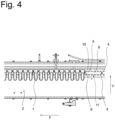
- the Fig.3 and 4 an embodiment according to the invention in which a second group 11 of fluid channels 4 is provided, the second group 11 being arranged below the container guide 8 and in particular below the guide surface 10.
- Both groups 5, 11 of fluid channels 4 are supplied with the fluid via the same drive channel 3 and are also identical in terms of their design and arrangement.
- the fluid channels of the second group 11 also run partially in a vertical direction, so that a certain buoyancy can be generated in the preforms 1.
- the second group 11 of fluid channels 4 serves to load the preforms 1 more evenly and in particular to generate an opposing tilting moment around the guide surface 10.
- the preforms 1 according to the Fig.4 can be transported much straighter, thereby reducing the problem described above.
Landscapes
- Engineering & Computer Science (AREA)
- Mechanical Engineering (AREA)
- Manufacturing & Machinery (AREA)
- Physics & Mathematics (AREA)
- Fluid Mechanics (AREA)
- Blow-Moulding Or Thermoforming Of Plastics Or The Like (AREA)
Abstract
Description
- Die vorliegende Erfindung betrifft eine Transportvorrichtung zum Transport von Behältern, insbesondere von Vorformlingen, mit einer sich entlang einer Förderrichtung erstreckenden Fördergasse und einem parallel dazu angeordneten Antriebskanal, wobei die Fördergasse eine Behälterführung mit einem sich in Förderrichtung erstreckenden Führungsschlitz aufweist und wobei eine erste Gruppe von oberhalb des Führungsschlitzes angeordneten Fluidkanälen vorgesehen ist, welche fluidwirkend mit der Fördergasse und dem zumindest einen Antriebskanal verbunden ist.
- Die Erfindung bezieht sich insbesondere auf Transportvorrichtungen aus der Getränkeindustrie. Entsprechend handelt es sich bei den Behältern vorzugsweise um Getränkebehälter, wobei bei derartigen Transportvorrichtungen üblicherweise Vorformlinge bzw. sogenannte Preforms transportiert werden. Diese Vorformlinge werden im Zuge einer Blasumformung zu Getränkebehältern ausgeformt. Hierzu müssen die Vorformlinge über eine Zuführeinrichtung der Blaseinrichtung zugeführt werden. Innerhalb der Zuführeinrichtung werden die Vorformlinge vereinzelt und ausgerichtet und sodann innerhalb einer Heizvorrichtung aufgewärmt. Das Aufheizen erweicht das Material der Vorformlinge, wobei es sich üblicherweise um einen thermoplastischen Kunststoff z. B. Polyethylenterephthalat (PET) handelt.
- Innerhalb der Blaseinrichtung erfolgt dann das Einbringen eines unter Druck stehenden Fluids in den Innenbereich der Vorformlinge, wodurch sich diese aufweiten und in einer vordefinierten Kontur eingepresst werden. Die sich so herausgebildeten Getränkebehälter können dann in einem anschließenden Prozessschritt befüllt, verschlossen und verpackt werden.
- Transportvorrichtungen der eingangs beschriebenen Art sind grundsätzlich aus dem Stand der Technik bekannt. Die Bewegung wird durch das Einbringen eines Fluidstroms bewirkt. Bei diesem Fluidstrom handelt es sich üblicherweise um einen Luftstrom, welcher gerichtet über die Fluidkanäle auf die Vorformlinge eingebracht wird, sodass diese infolgedessen entlang einer vordefinierten Transportstrecke innerhalb der Fördergasse bewegt werden. Der Fluidstrom wird hierbei zunächst in einen Antriebskanal eingebracht, wobei der Antriebskanal und die Fördergasse parallel zueinander angeordnet sind. In dem Antriebskanal verteilt sich das Fluid und wird sodann über die Vielzahl hintereinander angeordneter Fluidkanäle in die Fördergasse eingebracht. Hierbei wirken der Fluidstrom bzw. die einzelnen Teilfluidströme auf einen oberen Bereich der Vorformlinge ein, welcher üblicherweise bereits mit einem Außengewinde ausgebildet ist, wobei das Außengewinde der Aufnahme einer Verschlusskappe dient. Entsprechend sind die Fluidkanäle oberhalb des Führungsschlitzes angeordnet, wobei die Vorformlinge den Führungsschlitz durchgreifen, sodass entsprechend der fertig ausgebildete obere Bereich oberhalb des Führungsschlitzes und der später im Zuge einer Blassumformung umzuformende untere Bereich unterhalb des Führungsschlitzes angeordnet ist.
- Im Gegensatz zu sogenannten Transportrutschen werden die Vorformlinge aktiv angetrieben, während bei einer Transportrutsche die Bewegung der Preforms allein aufgrund des Eigengewichts und einer gewissen Schrägstellung der Fördergasse bewirkt wird. Im Gegensatz dazu kann bei einer mit einem Fluidstrom betriebenen Transportvorrichtung die Fördergasse im Allgemeinen horizontal angeordnet sein, wobei sich der Anwendungsbereich gegenüber den Transportrutschen wesentlich erweitert.
- Transportvorrichtungen der eingangs beschriebenen Art haben sich in der Praxis grundsätzlich bewährt. Allerdings hat sich gezeigt, dass die Vorformlinge aufgrund des oberhalb des Führungsschlitzes einwirkenden Fluidstroms verkippen und sich hierdurch im Bereich des Neckringes übereinander schieben können. Hierdurch werden die Vorformlinge einerseits stark mechanisch beansprucht. Zugleich können sich die Vorformlinge auch derart miteinander verhaken, dass der Transport gestört und sogar blockiert wird. Auch die Führung kann aufgrund der Reibung zwischen den Vorformlingen und der Oberfläche der Führung stark beansprucht werden.
- Vor diesem Hintergrund liegt der Erfindung die Aufgabe zugrunde, eine Transportvorrichtung anzugeben, welche einen ungestörten Betrieb insbesondere bei hohen Behälterdurchsätzen ermöglichen.
- Gegenstand und Lösung dieser Aufgabe ist eine Transportvorrichtung gemäß Patentanspruch 1. Demnach ist zusätzlich zur ersten Gruppe von Führungskanälen eine zweite Gruppe von unterhalb des Führungsschlitzes angeordneten Führungskanälen vorgesehen, wobei die unterhalb des Führungsschlitzes angeordneten Fluidkanäle der zweiten Gruppe mit der Fördergasse fluidwirkend verbunden ist.
- Durch eine solche Ausgestaltung werden die Behälter, insbesondere die Vorformlinge, einerseits oberhalb des Führungsschlitzes und andererseits unterhalb des Führungsschlitzes mit einem Fluidstrom beansprucht, wobei durch die zweite Gruppe von Fluidkanälen ein gegenüber der ersten Gruppe von Fluidkanälen gegensätzliches Kippmoment erzeugt wird, sodass eine Verkippung im Bereich der Führung wirksam reduziert, insbesondere vermieden, wird. Infolge dessen liegen die Behälter gleichmäßig auf der Führung auf, wobei insbesondere bei Vorformlingen die Gefahr verringert wird, dass diese im Bereich des Neckrings übereinander geschoben werden. Entsprechend wird die Gefahr einer Klemmung wirksam reduziert und auch die Behälter sowie die Führung deutlich weniger stark mechanisch beansprucht als bei den bislang bekannten Transportvorrichtungen.
- Gemäß einer bevorzugten Ausgestaltung der Erfindung sind die erste und die zweite Gruppe von Fluidkanälen in einer vertikalen Richtung bezüglich einer Führungsfläche der Behälterführung äquidistant angeordnet. Unter der Führungsfläche wird die Fläche der Führung verstanden, auf welcher die Behälter, insbesondere die Vorformlinge mit einem Neckring, aufliegen.
- Entsprechend handelt es sich um eine in vertikaler Richtung nach oben zeigende Fläche, welche als Abstützung für die Behälter die relevante Kippebene darstellt, über die die Behälter verkippen können.
- Durch eine äquidistante Anordnung der Führungskanäle kann sichergestellt werden, dass bei gleich einwirkenden Fluidströmen ein gleichgroßes Kippmoment um die Führungsebene erzeugt wird. Selbstverständlich sind aber auch Ausgestaltungen denkbar, bei denen sich die Anordnung der Führungskanäle zwischen der ersten und der zweiten Gruppe unterscheidet. Dies ist insbesondere dann sinnvoll, wenn beispielsweise die zweite Gruppe von Fluidkanälen mit einem geringeren oder größeren Fluidstrom betrieben wird.
- Bevorzugt sind die Fluidkanäle der ersten und der zweiten Gruppe zwischen 5 und 30 mm, besonders bevorzugt zwischen 10 und 25 mm, in einer senkrecht zur Förderrichtung verlaufenden vertikalen Richtung voneinander beabstandet. Die Führungsfläche der Behälterführung und die Fluidkanäle der ersten, und oder der zweiten Gruppe sind bevorzugt zwischen 5 und 25 mm.
- Eine besonders bevorzugte Ausgestaltung der Erfindung sieht ferner vor, dass die Fluidkanäle der zweiten Gruppe, bezüglich einer Draufsicht entlang der vertikalen Richtung versetzt zu den Fluidkanälen der ersten Gruppe angeordnet sind. Entsprechend sind die Fluidkanäle der ersten Gruppe bezüglich der Förderrichtung an anderen Positionen angeordnet als die Fluidkanäle der zweiten Gruppe. Alternativ kann auf einen solchen Versatz auch verzichtet werden, sodass entsprechend die Füllkanäle der ersten und der zweiten Gruppe bezüglich der Längsrichtung auf denselben Positionen angeordnet sind. Beide Varianten können je nach Einsatz der Transportvorrichtung von Vorteil sein. Durch eine Anordnung ohne Versatz wirken an denselben Positionen die Fluidströme auf die Vorformlinge ein, sodass ein sehr effektiver Ausgleich der Kippmomente bewirkt werden kann. Andererseits kann durch eine versetzte Anordnung ein gleichmäßigerer Antrieb der Behälter erfolgen, während zugleich die Kippmomente in ausreichender Art und Weise kompensiert werden. Die spezielle Anordnung kann sich dann insbesondere nach Art der zu transportierenden Behälter sowie dem Behälterdurchsatz richten.
- Da über die Fluidkanäle der ersten und der zweiten Gruppe ein Fluidraum in die Fördergasse eingebracht werden soll, kann es zweckmäßig sein, die zweite Gruppe fluidwirkend mit dem Antriebskanal zu verbinden. Entsprechend werden beide Gruppen von Fluidkanälen über denselben Antriebskanal mit dem Antriebsfluid versorgt. Hierbei ist dann sicherzustellen, dass der Antriebskanal über eine ausreichend große Höhe verfügt und zugleich, dass die Fluidkanäle beider Gruppen möglichst gleichmäßig und mit konstantem Fluidstrom versorgt werden können. Alternativ ist es selbstverständlich auch möglich lediglich die Fluidkanäle der ersten Gruppe über den Antriebskanal zu versorgen, wobei dann für die Fluidkanäle der zweiten Gruppe eine separate Versorgungseinheit vorzusehen ist.
- Eine solche Ausgestaltung kann beispielsweise derart sein, dass auf einer dem Antriebskanal abgewandten Seite der Fördergasse ein Stützkanal angeordnet ist, wobei die Fluidkanäle der zweiten Gruppe fluidwirkend mit dem Stützkanal verbunden sind. Entsprechend werden die Fluidkanäle der ersten Gruppe über den Antriebskanal und die Fluidkanäle der zweiten Gruppe über den Stützkanal betrieben. Alternativ ist es auch denkbar, dass sowohl der Antriebskanal als auch der Stützkanal auf derselben Seite der Fördergasse angeordnet sind und lediglich auf unterschiedlichen vertikalen Höhen übereinander angeordnet sind.
- Eine bevorzugte Ausgestaltung der Erfindung sieht vor, dass der Antriebskanal und die Fördergasse und/oder der Stützkanal und die Fördergasse jeweils über eine Seitenwandung voneinander getrennt sind, wobei die Fluidkanäle in der Seitenwandung angeordnet und/oder gebildet sind. Sofern die Fluidkanäle in der entsprechenden Seitenwandung gebildeten sind, handelt es sich insbesondere um Durchbrechungen in der Seitenwandung, insbesondere um Löcher, welche vorzugsweise rund oder aber auch eckig ausgebildet sind. Die zwischen dem Antriebskanal und der Fördergasse angeordnete Seitenwandung wird im Vorliegenden auch als erste Seitenwandung bezeichnet. Die gegenüberliegende Seitenwandlung der Fördergasse wird dann entsprechend als zweite Seitenwandung bezeichnet. Entsprechend kann der Stützkanal entweder an der ersten oder der zweiten Seitenwandung angeordnet sein.
- Bevorzugt sind ferner die Fluidkanäle der zweiten Gruppe bezüglich der Längsrichtung und einer senkrecht dazu verlaufenden Querrichtung schräg gestellt. Hierbei wird sich insbesondere an der Anordnung und Ausgestaltung der Fluidkanäle der ersten Gruppe orientiert, wobei die Fließkanäle beider Gruppen identisch angeordnet sein können. Insbesondere ist vorgesehen, dass die Fluidkanäle der ersten und/oder der zweiten Gruppe zumindest teilweise in Längsrichtung verlaufen und gegenüber der Querrichtung über einen Winkel schräg gestellt sind. Der Winkel beträgt vorzugsweise zwischen 20 und 40°, insbesondere zwischen 25 und 35°.
- Darüber hinaus kann vorgesehen sein, dass die Fluidkanäle der zweiten Gruppe bezüglich der Vertikalrichtung schräg gestellt sind. Dementsprechend ist vorgesehen, dass die Fluidkanäle der zweiten Gruppe dazu eingerichtet sind, einen Fluidstrom zu erzeugen, welcher eine Strömungskomponente in vertikaler Richtung aufweist, wodurch den Behältern, insbesondere den Vorformlingen, ein geringfügiger Auftrieb bewirkt wird. Durch diesen Auftrieb kann die Reibung zwischen der Behälterführung und dem Behälter verringert werden, sodass ein wesentlich besserer und effektiverer Durchsatz von Behältern möglich ist. Zugleich wird auch die Führungsfläche deutlich weniger belastet.
- Eine weitere bevorzugte Ausgestaltung sieht vor, dass der Antriebskanal und/oder der Stützkanal mit einem Fluidverdichter verbunden sind, wobei der Fluidverdichter bevorzugt zur Verdichtung der Umgebungsluft eingerichtet ist. Selbstverständlich können auch mehrere Fluidverdichter an den Antriebskanal und/oder den Stützkanal anschließen. Dies ist insbesondere dann sinnvoll, wenn mehrere Antriebskanäle und/oder mehrere Stützkanäle in Längsrichtung hintereinander angeordnet sind.
- Entsprechend erstreckt sich nicht ein Antriebskanal bzw. ein Stützkanal über die gesamte Länge der Fördergasse. Vielmehr sind mehrere Antriebs- und/oder Stützkanäle vorgesehen, über die eine gleichmäßige Einleitung von Fluidströmen bewerkstelligt werden kann. Gemäß einer solchen Ausgestaltung weist dann jeder Antriebskanal bzw. jeder Stützkanal einen eigenen Fluidverdichter auf. Alternativ ist es aber auch denkbar, lediglich einen Fluidverdichter vorzusehen, welcher dann sämtliche Antriebskanäle und/oder sämtliche Stützkanäle mit Fluid versorgt.
- Bei dem Fluid handelt es sich insbesondere um Umgebungsluft, welche in dem entsprechenden Fluidverdichter verdichtet wird. Vor einer Einleitung in den Antriebskanal bzw. in die Antriebskanäle und/oder in den Stützkanal bzw. die Stützkanäle kann dann auch noch eine Filtereinheit vorgesehen sein, welche die Umgebungsluft filtert und wobei sodann die so gefilterte Luft eingeleitet wird.
- Gegenstand der Erfindung ist ferner eine Blasformanlage mit einer Blaseinrichtung zum Blasumformen von Vorformlingen und zumindest einer Zuführeinrichtungen zur Zuführung der Vorformlinge in die Blaseinrichtung, wobei Zuführeinrichtungen zumindest eine erfindungsgemäße Transportvorrichtung aufweist. Insbesondere ist vor der Transportvorrichtung ein sogenannter Rollensortierer vorgesehen, welcher die einzelnen Vorformlinge ausrichtet, sodass diese gezielt in die Transportvorrichtung eingeleitet werden können.
- In der Transportvorrichtung erfolgt dann eine gewisse Beschleunigung der Vorformlinge, sodass diese in einen insbesondere rotierenden Vereinzelungsstern eingeleitet werden können. In diesem Vereinzelungsstern werden die Vorformlinge dann so vereinzelt, dass diese in eine Heizvorrichtung übergeben werden können. Hinter der Heizvorrichtung ist die eigentliche Blaseinrichtung angeordnet.
- Gegenstand der Erfindung ist ferner ein Verfahren zum Transport von Behältern, insbesondere in einer erfindungsgemäßen Transportvorrichtung, wobei die Behälter der Transportvorrichtung zugeführt und durch Beaufschlagung mit einem ersten Fluidstrom entlang einer Förderrichtung transportiert werden. Erfindungsgemäß werden die Behälter während des Transports mit einem zweiten Fluidstrom beaufschlagt, wobei der zweite Fluidstrom in vertikaler Richtung unterhalb des ersten Fluidstroms auf die Behälter einwirkt. Bei den Behältern handelt es sich bevorzugt um Vorformlinge.
- Insbesondere weisen die Behälter einen sogenannten Neckring auf, über den die Behälter auf der Behälterführung aufliegen, wobei der erste Fluidstom oberhalb des Neckrings und der zweite Fluidstrom unterhalb des Neckrings auf die Behälter einwirken. Bei den Behältern handelt es sich insbesondere um Getränkebehälter, wobei die Verwendung von Vorformlingen bzw. Preforms als besonders bevorzugt angesehen wird.
- Eine Weiterbildung des Verfahrens sieht vor, dass der erste und der zweite Luftstrom zumindest bezüglich einer Querrichtung entgegengesetzt auf die Vorformlinge einwirken. Dies kann beispielsweise dadurch erreicht werden, dass der erste Fluidstrom über eine erste Gruppe von Fluidkanälen und der zweite Fluidstrom über eine zweite Gruppe von Fluidkanälen eingeleitet wird, wobei diese Fluidkanäle an entgegengesetzten Seitenwandungen der Fördergasse angeordnet sind.
- Darüber hinaus sieht eine bevorzugte Ausgestaltung der Erfindung vor, dass der zweite Fluidstrom eine in vertikaler Richtung nach oben gerichtete Geschwindigkeitskomponente aufweist. Entsprechend wirkt dieser zweite Luftstrom derart auf die Behälter ein, dass die von den Behältern auf die Behälterführung einwirkende Kraft verringert wird. Hierdurch wird auch die Reibung zwischen der Führungsfläche und der Behälter verringert.
- Eine Weiterbildung sieht ferner vor, dass das Fluid des ersten und/oder des zweiten Fluidstroms Luft, insbesondere verdichtete Umgebungsluft ist.
- Im Folgenden wird die Erfindung anhand von Ausführungsbeispielen erläutert. Es zeigen:
- Fig. 1, 2
- eine Transportvorrichtung zum Transport von Vorformlingen in unterschiedlichen Ansichten,
- Fig. 3, 4
- eine erfindungsgemäße Transportvorrichtung in unterschiedlichen Ansichten.
- Die
Fig. 1 und2 zeigen eine Transportvorrichtung zum Transport von Vorformlingen 1 aus dem Stand der Technik. Hierbei weist die Transportvorrichtung eine Fördergasse 2 auf, welche sich entlang einer Förderrichtung F erstreckt. Entsprechend werden auch die Vorformlinge 1 entlang der Förderrichtung F transportiert. - Um einen solchen Transport zu ermöglichen, ist ein Antriebskanal 3 vorgesehen, welcher mit einem nicht näher dargestellten Fluidverdichter verbunden ist, sodass kontinuierlich ein Fluid, insbesondere verdichtete Umgebungsluft, in den Antriebskanal 3 eingeleitet werden kann. Dieses Fluid wird dann dazu genutzt, um die Vorformlinge 1 anzutreiben.
- Hierzu erstreckt sich der Antriebskanal 3 parallel zu der Fördergasse 2 in Förderrichtung F und weist darüber hinaus eine Vielzahl von Fluidkanälen 4 auf, wobei diese Fluidkanäle 4 in Förderrichtung F hintereinander angeordnet sind und eine gemeinsame erste Gruppe 5 bilden.
- Über diese Fluidkanäle 4, welche in einer der Fördergasse 2 zugewandten ersten Seitenwandung 6 gebildet sind, kann das Fluid in die Fördergasse 2 eintreten, wobei sich über jeden Fluidkanal 4 ein Teilfluidstrom ausbildet, welcher zumindest eine Komponente in Förderrichtung F aufweist, sodass die Vorformlinge 1 im Zuge der Einwirkung der Teilfluidströme in Förderrichtung F transportiert werden können. Entsprechend sind die Fluidkanäle 4 der ersten Gruppe 5 leicht schräg zur Förderrichtung F bzw. zur Querrichtung angeordnet.
- Wie der
Fig. 1 entnommen werden kann, weist die Fördergasse 2 einen Führungsschlitz 7 auf, welcher in einer Behälterführung 8 gebildet ist. Dieser Führungsschlitz 7 weist eine Breite in Querrichtung Q auf, welche einerseits so gewählt ist, dass die Vorformlinge 1 den Führungsschlitz 7 durchgreifen können. Andererseits können die Vorformlinge 1 aber auch mit einem Neckring 9 auf der Behälterführung bzw. auf einer Führungsfläche 10 aufliegen. - Wie man insbesondere
Fig. 2 entnehmen kann, sind die Fluidkanäle 4 oberhalb des Führungsschlitzes 7 und insbesondere oberhalb der Führungsfläche 10 angeordnet, sodass die Vorformlinge 1 leicht verkippen. Dies hat zur Folge, dass die Vorformlinge 1 sich insbesondere mit Ihrem Neckring 9 übereinander schieben können und sich infolgedessen miteinander verklemmen. Dies ist insbesondere bei hohen Behälterdurchsätzen der Fall. Darüber hinaus wird hierdurch auch die Behälterführung 8 und insbesondere die Führungsfläche 10 aufgrund der Reibung stark belastet. Von daher wird angestrebt, dass die Vorformlinge 1 möglichst gerade in der Behälterführung 8 transportiert werden. - Vor diesem Hintergrund zeigen die
Fig. 3 und4 eine erfindungsgemäße Ausgestaltung, bei der eine zweite Gruppe 11 von Fluidkanälen 4 vorgesehen ist, wobei die zweite Gruppe 11 unterhalb der Behälterführung 8 und insbesondere unterhalb der Führungsfläche 10 angeordnet. Beide Gruppen 5, 11 von Fluidkanälen 4 werden über den gleichen Antriebskanal 3 mit dem Fluid versorgt und sind auch hinsichtlich ihrer Ausgestaltung und Einrichtung identisch ausgebildet. Zusätzlich ist es denkbar, dass die Fluidkanäle der zweiten Gruppe 11 auch teilweise in einer vertikalen Richtung verlaufen, sodass hierdurch ein gewisser Auftrieb in den Vorformlingen 1 erzeugt werden kann. Insbesondere dient die zweite Gruppe 11 von Fluidkanälen 4 aber dazu, die Vorformlinge 1 gleichmäßiger zu belasten und insbesondere ein gegenläufiges Kippmoment um die Führungsfläche 10 zu erzeugen. Im Ergebnis können die Vorformlinge 1 gemäß derFig. 4 wesentlich gerader transportiert werden, wodurch sich die zuvor beschriebene Problematik verringert. -
- Vorformlingen 1
- Fördergasse 2
- Antriebskanal 3
- Fluidkanälen 4
- Gruppe 5
- Seitenwandung 6
- Führungsschlitz 7
- Behälterführung 8
- Neckring 9
- Führungsfläche 10
- Gruppe 11
- Förderrichtung F
- Richtung V
- Querrichtung Q
Claims (16)
- Transportvorrichtung zum Transport von Behältern, insbesondere von Vorformlingen (1), mit einer sich entlang einer Förderrichtung (F) erstreckenden Fördergasse (2) und einem parallel dazu angeordneten Antriebskanal (3), wobei die Fördergasse (2) eine Behälterführung (8) mit einem sich in Förderrichtung (F) erstreckenden Führungsschlitz (7) aufweist und wobei eine erste Gruppe (5) von oberhalb des Führungsschlitzes (7) angeordneten Fluidkanälen (4) vorgesehen ist, welche fluidwirkend mit der Fördergasse (2) und dem zumindest einen Antriebskanal (3) verbunden ist,
dadurch gekennzeichnet, dass
eine zweite Gruppe (11) von unterhalb des Führungsschlitzes (7) angeordneten Fluidkanälen (4) mit der Fördergasse (2) fluidwirkend verbunden ist. - Transportvorrichtung nach Anspruch 1, dadurch gekennzeichnet, dass die Fluidkanäle (4) der ersten und der zweiten Gruppe (5, 11) zwischen 5 und 30 mm in einer senkrecht zur Förderrichtung (F) verlaufenden vertikalen Richtung (V) voneinander beabstandet sind.
- Transportvorrichtung nach einem der vorangegangenen Ansprüche, dadurch gekennzeichnet, dass die Behälterführung (8) eine Führungsfläche (10) aufweist und wobei die Fluidkanäle (4) der zweiten Gruppe (11) zwischen 5 und 25 mm in vertikaler Richtung (V) von der Führungsfläche (10) beabstandet sind.
- Transportvorrichtung nach einem der vorangegangenen Ansprüche, dadurch gekennzeichnet, dass die Fluidkanäle (4) der zweiten Gruppe (11) bezüglich einer Draufsicht entlang der vertikalen Richtung (V) versetzt zu den Fluidkanälen (4) der ersten Gruppe (5) angeordnet sind.
- Transportvorrichtung nach einem der vorangegangenen Ansprüche, dadurch gekennzeichnet, dass die Fluidkanäle (4) der zweiten Gruppe (11) fluidwirkend mit dem Antriebskanal (3) verbunden sind.
- Transportvorrichtung nach einem der Ansprüche 1 bis 4, dadurch gekennzeichnet, dass auf einer dem Antriebskanal (3) abgewandten Seite der Fördergasse (2) ein Stützkanal angeordnet ist, wobei die Fluidkanäle (4) der zweiten Gruppe (11) fluidwirkend mit dem Stützkanal verbunden sind.
- Transportvorrichtung nach einem der vorangegangenen Ansprüche, dadurch gekennzeichnet, dass der Antriebskanal (3) und die Fördergasse (2) und/oder der Stützkanal und die Fördergasse (2) jeweils über eine Seitenwandung (6) voneinander getrennt sind, wobei die Fluidkanäle (4) in der Seitenwandung (6) angeordnet und/oder gebildet sind.
- Transportvorrichtung nach einem der vorangegangenen Ansprüche, dadurch gekennzeichnet, dass die Fluidkanäle (4) der zweiten Gruppe (11) bezüglich der Förderrichtung (F) und einer senkrecht dazu verlaufenden Querrichtung (Q) schräg gestellt sind.
- Transportvorrichtung nach einem der vorangegangenen Ansprüche, dadurch gekennzeichnet, dass die Fluidkanäle (4) der zweiten Gruppe (11) bezüglich der vertikalen Richtung (V) schräg gestellt sind.
- Transportvorrichtung nach einem der vorangegangenen Ansprüche, dadurch gekennzeichnet, dass der Antriebskanal (3) und/oder der Stützkanal (2) mit einem Fluidverdichter verbunden sind, wobei der Fluidverdichter bevorzugt zur Verdichtung der Umgebungsluft eingerichtet ist.
- Blasformanlage mit einer Blaseinrichtung zur Blasumformung von Vorformlingen und zumindest einer Zuführeinrichtung zur Zuführung der Vorformlinge in die Blaseinrichtung, wobei die Zuführeinrichtung zumindest eine Transportvorrichtung nach einem der vorangegangenen Ansprüche aufweist.
- Verfahren zum Transport von Behältern, insbesondere von Vorformlingen (1), in einer Transportvorrichtung insbesondere nach einem der Ansprüche 1 bis 10, wobei die Behälter der Transportvorrichtung zugeführt und durch Beaufschlagung mit einem ersten Fluidstrom entlang einer Förderrichtung (F) transportiert werden, dadurch gekennzeichnet, dass die Behälter während des Transports mit einem zweiten Fluidstrom beaufschlagt werden, wobei der zweite Fluidstrom in vertikaler Richtung (V) unterhalb des ersten Fluidstroms auf die Behälter einwirkt.
- Verfahren nach Anspruch 12, dadurch gekennzeichnet, dass die Behälter über einen Neckring (9) auf der Behälterführung (8) aufliegen, wobei der erste Fluidstrom oberhalb des Neckrings (9) und der zweite Fluidstrom unterhalb des Neckrings (9) auf die Behälter einwirken.
- Verfahren nach Anspruch 12 oder 13, dadurch gekennzeichnet, dass der erste und der zweite Luftstrom zumindest bezüglich einer Querrichtung (Q) entgegengesetzt auf die Behälter einwirken.
- Verfahren nach einem der Ansprüche 12 bis 14, dadurch gekennzeichnet, dass der zweite Fluidstrom eine in vertikaler Richtung (V) nach oben gerichtete Geschwindigkeitskomponente aufweist.
- Verfahren nach einem der Ansprüche 12 bis 15, dadurch gekennzeichnet, dass das Fluid des ersten und/oder des zweiten Fluidstroms Luft, insbesondere verdichtete Umgebungsluft, ist.
Applications Claiming Priority (1)
| Application Number | Priority Date | Filing Date | Title |
|---|---|---|---|
| DE102022131401.4A DE102022131401A1 (de) | 2022-11-28 | 2022-11-28 | Transportvorrichtung zum Transport von Vorformlingen, Blasformanlage sowie Verfahren zum Transport |
Publications (2)
| Publication Number | Publication Date |
|---|---|
| EP4375046A1 true EP4375046A1 (de) | 2024-05-29 |
| EP4375046B1 EP4375046B1 (de) | 2025-09-03 |
Family
ID=88647555
Family Applications (1)
| Application Number | Title | Priority Date | Filing Date |
|---|---|---|---|
| EP23207107.6A Active EP4375046B1 (de) | 2022-11-28 | 2023-10-31 | Transportvorrichtung zum transport von vorformlingen, blasformanlage sowie verfahren zum transport |
Country Status (2)
| Country | Link |
|---|---|
| EP (1) | EP4375046B1 (de) |
| DE (1) | DE102022131401A1 (de) |
Cited By (1)
| Publication number | Priority date | Publication date | Assignee | Title |
|---|---|---|---|---|
| DE102024133247A1 (de) | 2024-11-13 | 2026-05-13 | Krones Aktiengesellschaft | Vorrichtung und Verfahren zum Transportieren von Kunststoffvorformlingen |
Citations (5)
| Publication number | Priority date | Publication date | Assignee | Title |
|---|---|---|---|---|
| US4284370A (en) * | 1978-11-16 | 1981-08-18 | Danler Richard W | Air conveyor for bottles and bottle preforms |
| US20020192038A1 (en) * | 1999-12-22 | 2002-12-19 | Joel Trenel | Method for forming a train of suspended objects transported under the influence of air jets, and conveying section for carrying out said method |
| DE102009009866A1 (de) * | 2009-02-20 | 2010-08-26 | Krones Ag | Vorrichtung zum Transport von Vorformlingen |
| DE102009016593A1 (de) * | 2009-04-08 | 2010-10-14 | Krones Ag | Vorrichtung zum Transport von Vorformlingen |
| EP3165345A1 (de) * | 2015-11-05 | 2017-05-10 | BONINO S.p.A. con unico azionista | Förderer zum transportieren von vorformen oder ähnlichen objekten und system zum ausrichten von objekten |
Family Cites Families (7)
| Publication number | Priority date | Publication date | Assignee | Title |
|---|---|---|---|---|
| IT1234023B (it) | 1989-03-08 | 1992-04-24 | Sarcmi Spa | Trasportatore a getti d'aria combinati per il convogliamento ottimizzato di bottiglie sospese |
| US5161919A (en) | 1991-08-06 | 1992-11-10 | Simplimatic Engineering Company | Bottle air conveyor |
| US5611647A (en) | 1994-08-17 | 1997-03-18 | Ouellette Machinery Systems, Inc. | Diverter for bottle air conveyor |
| US5785169A (en) | 1996-10-18 | 1998-07-28 | Vt Zurich Marketing Pte. Ltd. | Conveyor assembly of the conveying of open containers |
| FR2781470B1 (fr) * | 1998-07-21 | 2000-10-13 | Netra Systems | Convoyeur a air pour le transport d'articles et procede de deblocage d'articles |
| DE102005048358A1 (de) * | 2004-11-30 | 2006-08-24 | Sig Technology Ltd. | Verfahren und Vorrichtung zum Transport von Vorformlingen |
| DE102011013471A1 (de) | 2011-03-03 | 2012-09-06 | Khs Corpoplast Gmbh | Verfahren und Vorrichtung zum Sortieren von Vorformlingen |
-
2022
- 2022-11-28 DE DE102022131401.4A patent/DE102022131401A1/de active Pending
-
2023
- 2023-10-31 EP EP23207107.6A patent/EP4375046B1/de active Active
Patent Citations (5)
| Publication number | Priority date | Publication date | Assignee | Title |
|---|---|---|---|---|
| US4284370A (en) * | 1978-11-16 | 1981-08-18 | Danler Richard W | Air conveyor for bottles and bottle preforms |
| US20020192038A1 (en) * | 1999-12-22 | 2002-12-19 | Joel Trenel | Method for forming a train of suspended objects transported under the influence of air jets, and conveying section for carrying out said method |
| DE102009009866A1 (de) * | 2009-02-20 | 2010-08-26 | Krones Ag | Vorrichtung zum Transport von Vorformlingen |
| DE102009016593A1 (de) * | 2009-04-08 | 2010-10-14 | Krones Ag | Vorrichtung zum Transport von Vorformlingen |
| EP3165345A1 (de) * | 2015-11-05 | 2017-05-10 | BONINO S.p.A. con unico azionista | Förderer zum transportieren von vorformen oder ähnlichen objekten und system zum ausrichten von objekten |
Cited By (2)
| Publication number | Priority date | Publication date | Assignee | Title |
|---|---|---|---|---|
| DE102024133247A1 (de) | 2024-11-13 | 2026-05-13 | Krones Aktiengesellschaft | Vorrichtung und Verfahren zum Transportieren von Kunststoffvorformlingen |
| EP4744861A1 (de) | 2024-11-13 | 2026-05-20 | Krones AG | Vorrichtung und verfahren zum transportieren von kunststoffvorformlingen |
Also Published As
| Publication number | Publication date |
|---|---|
| EP4375046B1 (de) | 2025-09-03 |
| DE102022131401A1 (de) | 2024-05-29 |
Similar Documents
| Publication | Publication Date | Title |
|---|---|---|
| EP3476779B1 (de) | Vorrichtung und verfahren zum sortieren und vereinzeln von verschlusskappen | |
| DE102008049311B4 (de) | Vorrichtung zum Auspacken von Flaschen aus einer Verpackungseinheit | |
| EP2635510A1 (de) | Transportvorrichtung zum transportieren von behältern | |
| EP4375046B1 (de) | Transportvorrichtung zum transport von vorformlingen, blasformanlage sowie verfahren zum transport | |
| EP4026778A2 (de) | Verfahren und vorrichtung zum verpacken von hohlgläsern | |
| WO2022129342A1 (de) | Behälterzuführvorrichtung und verfahren zum betreiben der behälterzuführvorrichtung | |
| EP4601976A1 (de) | Vorrichtung zur förderung und vereinzelung von werkstücken | |
| EP2859802B1 (de) | Vorrichtung und verfahren zum sortierfördern von rauchartikeln | |
| EP4339136A1 (de) | Vereinzelungsvorrichtung sowie verfahren zum vereinzeln von vorformlingen | |
| EP4029811A1 (de) | Förderband zum transportieren von fördergut und verpackungslinie einer verpackungsanlage mit einem solchen förderband | |
| EP3544780A1 (de) | Verfahren und system zum transportieren und manipulieren von zu gebinden zusammengefassten getränkebehältnissen sowie zum einleiten mindestens eines bestimmten prozesses im falle einer aus einer handhabung resultierenden beschädigung eines gebindes | |
| DE19540992A1 (de) | Vorrichtung zum ausgerichteten Zuführen und Auflockern von Stapeln flacher Gegenstände | |
| EP4556128B1 (de) | Sortiervorrichtung zum aussondern von bestandteilen aus einem materialstrom sowie entsprechend ausgestattete anlage und verfahren | |
| EP4375220A1 (de) | Steigförderer zum fördern von behältern | |
| DE102018219010A1 (de) | Band-Umreifungsmaschine zum Umreifen eines Gutes mit einem verschweißbaren Kunststoffband | |
| DE202022105815U1 (de) | Vorrichtung zur Förderung und Vereinzelung von Werkstücken | |
| EP3571146B1 (de) | Sortierverfahren für hohlkörper und sortiervorrichtung | |
| AT503551B1 (de) | Vereinzelungssystem für feste, insbesondere sperrige produkte | |
| EP4606744A1 (de) | Vorrichtung und verfahren zum umgang mit getränkebehältern | |
| DE102022114820A1 (de) | Rollensortierer DirectLink | |
| DE102024107945A1 (de) | Einteilvorrichtung, Verfahren zum Umrüsten einer Einteilvorrichtung und Handhabungssystem | |
| DE102024103090A1 (de) | Transportanordnung, Blasmaschinenanordnung sowie Verfahren zum Transport von Behältern | |
| DE102005017899B4 (de) | Vorrichtung zum Abteilen einer Lage von mehreren dicht nebeneinander angeordneten Behältnissen aus einem Behälterstrom | |
| DE102007061195A1 (de) | Vorrichtung zum Transportieren von Behältnissen | |
| DE102004058662A1 (de) | Vorrichtung zum Zuführen kugelförmiger Gegenstände in einen Behälter |
Legal Events
| Date | Code | Title | Description |
|---|---|---|---|
| PUAI | Public reference made under article 153(3) epc to a published international application that has entered the european phase |
Free format text: ORIGINAL CODE: 0009012 |
|
| STAA | Information on the status of an ep patent application or granted ep patent |
Free format text: STATUS: THE APPLICATION HAS BEEN PUBLISHED |
|
| AK | Designated contracting states |
Kind code of ref document: A1 Designated state(s): AL AT BE BG CH CY CZ DE DK EE ES FI FR GB GR HR HU IE IS IT LI LT LU LV MC ME MK MT NL NO PL PT RO RS SE SI SK SM TR |
|
| STAA | Information on the status of an ep patent application or granted ep patent |
Free format text: STATUS: REQUEST FOR EXAMINATION WAS MADE |
|
| 17P | Request for examination filed |
Effective date: 20241129 |
|
| RBV | Designated contracting states (corrected) |
Designated state(s): AL AT BE BG CH CY CZ DE DK EE ES FI FR GB GR HR HU IE IS IT LI LT LU LV MC ME MK MT NL NO PL PT RO RS SE SI SK SM TR |
|
| GRAP | Despatch of communication of intention to grant a patent |
Free format text: ORIGINAL CODE: EPIDOSNIGR1 |
|
| STAA | Information on the status of an ep patent application or granted ep patent |
Free format text: STATUS: GRANT OF PATENT IS INTENDED |
|
| RIC1 | Information provided on ipc code assigned before grant |
Ipc: B29L 31/00 20060101ALN20250320BHEP Ipc: B29K 67/00 20060101ALN20250320BHEP Ipc: B65G 51/03 20060101ALN20250320BHEP Ipc: B29C 49/06 20060101ALN20250320BHEP Ipc: B29C 49/42 20060101AFI20250320BHEP |
|
| INTG | Intention to grant announced |
Effective date: 20250402 |
|
| GRAS | Grant fee paid |
Free format text: ORIGINAL CODE: EPIDOSNIGR3 |
|
| GRAA | (expected) grant |
Free format text: ORIGINAL CODE: 0009210 |
|
| STAA | Information on the status of an ep patent application or granted ep patent |
Free format text: STATUS: THE PATENT HAS BEEN GRANTED |
|
| AK | Designated contracting states |
Kind code of ref document: B1 Designated state(s): AL AT BE BG CH CY CZ DE DK EE ES FI FR GB GR HR HU IE IS IT LI LT LU LV MC ME MK MT NL NO PL PT RO RS SE SI SK SM TR |
|
| REG | Reference to a national code |
Ref country code: CH Ref legal event code: EP |
|
| REG | Reference to a national code |
Ref country code: DE Ref legal event code: R096 Ref document number: 502023001722 Country of ref document: DE |
|
| REG | Reference to a national code |
Ref country code: IE Ref legal event code: FG4D Free format text: LANGUAGE OF EP DOCUMENT: GERMAN |
|
| REG | Reference to a national code |
Ref country code: NL Ref legal event code: MP Effective date: 20250903 |
|
| PGFP | Annual fee paid to national office [announced via postgrant information from national office to epo] |
Ref country code: DE Payment date: 20251021 Year of fee payment: 3 |
|
| PG25 | Lapsed in a contracting state [announced via postgrant information from national office to epo] |
Ref country code: NO Free format text: LAPSE BECAUSE OF FAILURE TO SUBMIT A TRANSLATION OF THE DESCRIPTION OR TO PAY THE FEE WITHIN THE PRESCRIBED TIME-LIMIT Effective date: 20251203 |
|
| REG | Reference to a national code |
Ref country code: LT Ref legal event code: MG9D |
|
| P01 | Opt-out of the competence of the unified patent court (upc) registered |
Free format text: CASE NUMBER: UPC_APP_0014561_4375046/2025 Effective date: 20251125 |
|
| PG25 | Lapsed in a contracting state [announced via postgrant information from national office to epo] |
Ref country code: FI Free format text: LAPSE BECAUSE OF FAILURE TO SUBMIT A TRANSLATION OF THE DESCRIPTION OR TO PAY THE FEE WITHIN THE PRESCRIBED TIME-LIMIT Effective date: 20250903 |
|
| PGFP | Annual fee paid to national office [announced via postgrant information from national office to epo] |
Ref country code: IT Payment date: 20251031 Year of fee payment: 3 |
|
| PG25 | Lapsed in a contracting state [announced via postgrant information from national office to epo] |
Ref country code: HR Free format text: LAPSE BECAUSE OF FAILURE TO SUBMIT A TRANSLATION OF THE DESCRIPTION OR TO PAY THE FEE WITHIN THE PRESCRIBED TIME-LIMIT Effective date: 20250903 |
|
| PGFP | Annual fee paid to national office [announced via postgrant information from national office to epo] |
Ref country code: FR Payment date: 20251030 Year of fee payment: 3 |
|
| PG25 | Lapsed in a contracting state [announced via postgrant information from national office to epo] |
Ref country code: GR Free format text: LAPSE BECAUSE OF FAILURE TO SUBMIT A TRANSLATION OF THE DESCRIPTION OR TO PAY THE FEE WITHIN THE PRESCRIBED TIME-LIMIT Effective date: 20251204 |
|
| PG25 | Lapsed in a contracting state [announced via postgrant information from national office to epo] |
Ref country code: SE Free format text: LAPSE BECAUSE OF FAILURE TO SUBMIT A TRANSLATION OF THE DESCRIPTION OR TO PAY THE FEE WITHIN THE PRESCRIBED TIME-LIMIT Effective date: 20250903 |
|
| PG25 | Lapsed in a contracting state [announced via postgrant information from national office to epo] |
Ref country code: LV Free format text: LAPSE BECAUSE OF FAILURE TO SUBMIT A TRANSLATION OF THE DESCRIPTION OR TO PAY THE FEE WITHIN THE PRESCRIBED TIME-LIMIT Effective date: 20250903 |
|
| PG25 | Lapsed in a contracting state [announced via postgrant information from national office to epo] |
Ref country code: BG Free format text: LAPSE BECAUSE OF FAILURE TO SUBMIT A TRANSLATION OF THE DESCRIPTION OR TO PAY THE FEE WITHIN THE PRESCRIBED TIME-LIMIT Effective date: 20250903 Ref country code: PL Free format text: LAPSE BECAUSE OF FAILURE TO SUBMIT A TRANSLATION OF THE DESCRIPTION OR TO PAY THE FEE WITHIN THE PRESCRIBED TIME-LIMIT Effective date: 20250903 |
|
| PG25 | Lapsed in a contracting state [announced via postgrant information from national office to epo] |
Ref country code: RS Free format text: LAPSE BECAUSE OF FAILURE TO SUBMIT A TRANSLATION OF THE DESCRIPTION OR TO PAY THE FEE WITHIN THE PRESCRIBED TIME-LIMIT Effective date: 20251203 |
|
| PG25 | Lapsed in a contracting state [announced via postgrant information from national office to epo] |
Ref country code: ES Free format text: LAPSE BECAUSE OF FAILURE TO SUBMIT A TRANSLATION OF THE DESCRIPTION OR TO PAY THE FEE WITHIN THE PRESCRIBED TIME-LIMIT Effective date: 20250903 |
|
| PG25 | Lapsed in a contracting state [announced via postgrant information from national office to epo] |
Ref country code: NL Free format text: LAPSE BECAUSE OF FAILURE TO SUBMIT A TRANSLATION OF THE DESCRIPTION OR TO PAY THE FEE WITHIN THE PRESCRIBED TIME-LIMIT Effective date: 20250903 |
|
| PG25 | Lapsed in a contracting state [announced via postgrant information from national office to epo] |
Ref country code: SM Free format text: LAPSE BECAUSE OF FAILURE TO SUBMIT A TRANSLATION OF THE DESCRIPTION OR TO PAY THE FEE WITHIN THE PRESCRIBED TIME-LIMIT Effective date: 20250903 |
|
| PG25 | Lapsed in a contracting state [announced via postgrant information from national office to epo] |
Ref country code: RO Free format text: LAPSE BECAUSE OF FAILURE TO SUBMIT A TRANSLATION OF THE DESCRIPTION OR TO PAY THE FEE WITHIN THE PRESCRIBED TIME-LIMIT Effective date: 20250903 |
|
| PG25 | Lapsed in a contracting state [announced via postgrant information from national office to epo] |
Ref country code: IS Free format text: LAPSE BECAUSE OF FAILURE TO SUBMIT A TRANSLATION OF THE DESCRIPTION OR TO PAY THE FEE WITHIN THE PRESCRIBED TIME-LIMIT Effective date: 20260103 |
|
| PG25 | Lapsed in a contracting state [announced via postgrant information from national office to epo] |
Ref country code: CZ Free format text: LAPSE BECAUSE OF FAILURE TO SUBMIT A TRANSLATION OF THE DESCRIPTION OR TO PAY THE FEE WITHIN THE PRESCRIBED TIME-LIMIT Effective date: 20250903 Ref country code: PT Free format text: LAPSE BECAUSE OF FAILURE TO SUBMIT A TRANSLATION OF THE DESCRIPTION OR TO PAY THE FEE WITHIN THE PRESCRIBED TIME-LIMIT Effective date: 20260105 |
|
| PG25 | Lapsed in a contracting state [announced via postgrant information from national office to epo] |
Ref country code: EE Free format text: LAPSE BECAUSE OF FAILURE TO SUBMIT A TRANSLATION OF THE DESCRIPTION OR TO PAY THE FEE WITHIN THE PRESCRIBED TIME-LIMIT Effective date: 20250903 Ref country code: SK Free format text: LAPSE BECAUSE OF FAILURE TO SUBMIT A TRANSLATION OF THE DESCRIPTION OR TO PAY THE FEE WITHIN THE PRESCRIBED TIME-LIMIT Effective date: 20250903 |
|
| REG | Reference to a national code |
Ref country code: DE Ref legal event code: R026 Ref document number: 502023001722 Country of ref document: DE |
|
| PLBI | Opposition filed |
Free format text: ORIGINAL CODE: 0009260 |
|
| REG | Reference to a national code |
Ref country code: CH Ref legal event code: L10 Free format text: ST27 STATUS EVENT CODE: U-0-0-L10-L00 (AS PROVIDED BY THE NATIONAL OFFICE) Effective date: 20260611 |
|
| PG25 | Lapsed in a contracting state [announced via postgrant information from national office to epo] |
Ref country code: LU Free format text: LAPSE BECAUSE OF NON-PAYMENT OF DUE FEES Effective date: 20251031 |
|
| PLAX | Notice of opposition and request to file observation + time limit sent |
Free format text: ORIGINAL CODE: EPIDOSNOBS2 |
|
| REG | Reference to a national code |
Ref country code: BE Ref legal event code: MM Effective date: 20251031 |
|
| PG25 | Lapsed in a contracting state [announced via postgrant information from national office to epo] |
Ref country code: MC Free format text: LAPSE BECAUSE OF FAILURE TO SUBMIT A TRANSLATION OF THE DESCRIPTION OR TO PAY THE FEE WITHIN THE PRESCRIBED TIME-LIMIT Effective date: 20250903 Ref country code: LT Free format text: LAPSE BECAUSE OF FAILURE TO SUBMIT A TRANSLATION OF THE DESCRIPTION OR TO PAY THE FEE WITHIN THE PRESCRIBED TIME-LIMIT Effective date: 20250903 |
|
| 26 | Opposition filed |
Opponent name: KRONES AG Effective date: 20260601 |
|
| PG25 | Lapsed in a contracting state [announced via postgrant information from national office to epo] |
Ref country code: DK Free format text: LAPSE BECAUSE OF FAILURE TO SUBMIT A TRANSLATION OF THE DESCRIPTION OR TO PAY THE FEE WITHIN THE PRESCRIBED TIME-LIMIT Effective date: 20250903 |
|
| PG25 | Lapsed in a contracting state [announced via postgrant information from national office to epo] |
Ref country code: BE Free format text: LAPSE BECAUSE OF NON-PAYMENT OF DUE FEES Effective date: 20251031 |