EP4374994A1 - Workpiece support device for machine tool, machine tool, and method for using machine tool - Google Patents
Workpiece support device for machine tool, machine tool, and method for using machine tool Download PDFInfo
- Publication number
- EP4374994A1 EP4374994A1 EP21955088.6A EP21955088A EP4374994A1 EP 4374994 A1 EP4374994 A1 EP 4374994A1 EP 21955088 A EP21955088 A EP 21955088A EP 4374994 A1 EP4374994 A1 EP 4374994A1
- Authority
- EP
- European Patent Office
- Prior art keywords
- support
- rotating shaft
- workpiece
- axis
- hole
- Prior art date
- Legal status (The legal status is an assumption and is not a legal conclusion. Google has not performed a legal analysis and makes no representation as to the accuracy of the status listed.)
- Granted
Links
Images
















Classifications
-
- B—PERFORMING OPERATIONS; TRANSPORTING
- B23—MACHINE TOOLS; METAL-WORKING NOT OTHERWISE PROVIDED FOR
- B23B—TURNING; BORING
- B23B13/00—Arrangements for automatically conveying or chucking or guiding stock
- B23B13/12—Accessories, e.g. stops, grippers
- B23B13/126—Supports
-
- B—PERFORMING OPERATIONS; TRANSPORTING
- B23—MACHINE TOOLS; METAL-WORKING NOT OTHERWISE PROVIDED FOR
- B23B—TURNING; BORING
- B23B3/00—General-purpose turning-machines or devices, e.g. centre lathes with feed rod and lead screw; Sets of turning-machines
- B23B3/04—Turning-machines in which the workpiece is rotated by means at a distance from the headstock
-
- B—PERFORMING OPERATIONS; TRANSPORTING
- B23—MACHINE TOOLS; METAL-WORKING NOT OTHERWISE PROVIDED FOR
- B23B—TURNING; BORING
- B23B1/00—Methods for turning or working essentially requiring the use of turning-machines; Use of auxiliary equipment in connection with such methods
-
- B—PERFORMING OPERATIONS; TRANSPORTING
- B23—MACHINE TOOLS; METAL-WORKING NOT OTHERWISE PROVIDED FOR
- B23B—TURNING; BORING
- B23B7/00—Automatic or semi-automatic turning-machines with a single working-spindle, e.g. controlled by cams; Equipment therefor; Features common to automatic and semi-automatic turning-machines with one or more working-spindles
- B23B7/02—Automatic or semi-automatic machines for turning of stock
- B23B7/06—Automatic or semi-automatic machines for turning of stock with sliding headstock
-
- B—PERFORMING OPERATIONS; TRANSPORTING
- B23—MACHINE TOOLS; METAL-WORKING NOT OTHERWISE PROVIDED FOR
- B23B—TURNING; BORING
- B23B2260/00—Details of constructional elements
- B23B2260/042—Collets of known configuration, i.e. devices using a collet
-
- B—PERFORMING OPERATIONS; TRANSPORTING
- B23—MACHINE TOOLS; METAL-WORKING NOT OTHERWISE PROVIDED FOR
- B23B—TURNING; BORING
- B23B2270/00—Details of turning, boring or drilling machines, processes or tools not otherwise provided for
- B23B2270/30—Chip guiding or removal
-
- B—PERFORMING OPERATIONS; TRANSPORTING
- B23—MACHINE TOOLS; METAL-WORKING NOT OTHERWISE PROVIDED FOR
- B23Q—DETAILS, COMPONENTS, OR ACCESSORIES FOR MACHINE TOOLS, e.g. ARRANGEMENTS FOR COPYING OR CONTROLLING; MACHINE TOOLS IN GENERAL CHARACTERISED BY THE CONSTRUCTION OF PARTICULAR DETAILS OR COMPONENTS; COMBINATIONS OR ASSOCIATIONS OF METAL-WORKING MACHINES, NOT DIRECTED TO A PARTICULAR RESULT
- B23Q1/00—Members which are comprised in the general build-up of a form of machine, particularly relatively large fixed members
- B23Q1/72—Auxiliary arrangements; Interconnections between auxiliary tables and movable machine elements
- B23Q1/76—Steadies; Rests
- B23Q1/763—Rotating steadies or rests
-
- B—PERFORMING OPERATIONS; TRANSPORTING
- B23—MACHINE TOOLS; METAL-WORKING NOT OTHERWISE PROVIDED FOR
- B23Q—DETAILS, COMPONENTS, OR ACCESSORIES FOR MACHINE TOOLS, e.g. ARRANGEMENTS FOR COPYING OR CONTROLLING; MACHINE TOOLS IN GENERAL CHARACTERISED BY THE CONSTRUCTION OF PARTICULAR DETAILS OR COMPONENTS; COMBINATIONS OR ASSOCIATIONS OF METAL-WORKING MACHINES, NOT DIRECTED TO A PARTICULAR RESULT
- B23Q11/00—Accessories fitted to machine tools for keeping tools or parts of the machine in good working condition or for cooling work; Safety devices specially combined with or arranged in, or specially adapted for use in connection with, machine tools
- B23Q11/08—Protective coverings for parts of machine tools; Splash guards
- B23Q11/0883—Protective coverings for parts of machine tools; Splash guards for spindles, e.g. for their bearings or casings
Definitions
- the present invention relates to a workpiece support for a machine tool, a machine tool, and a method of using a machine tool.
- a machine tool is known to machine an elongate workpiece while restricting bending of the workpiece using a guide bushing.
- Patent Literature 1 discloses a spindle movable lathe.
- the spindle movable lathe recited in Patent Literature 1 includes a spindle that holds a workpiece, a headstock, a guide bushing holder provided at a forward position relative to the spindle and including a guide bushing configured to slidably guide the workpiece, and a support base on which the guide bushing holder is mounted.
- the guide bushing holder is removable relative to the support base.
- a cover member instead of the guide bushing holder, a cover member is attachable at a position corresponding to the guide bushing.
- the cover member has a protection hole in which a leading end portion of the spindle is insertable.
- the workpiece support, the machine tool, and the method prevent foreign matter from entering a gap between a rotating shaft and a through hole capable of supporting a guide bushing adapter.
- a workpiece support for a machine tool includes a rotating shaft, a first support, a second support, and an air supplier.
- the rotating shaft is configured to support a workpiece and rotatable about a first axis.
- the first support has a through hole capable of supporting a guide bushing adapter configured to hold a guide bushing, and is configured to receive a leading end portion of the rotating shaft in the through hole.
- the second support supports the rotating shaft and is configured to move the rotating shaft in a direction parallel to the first axis relative to the first support.
- the air supplier is configured to supply air to the first support. An ejection opening through which the air supplied from the air supplier is ejected is formed at an inner circumferential surface of the through hole of the first support.
- a machine tool includes a workpiece support, a tool holder, and a second drive.
- the tool holder is configured to hold a tool.
- the second drive is configured to move the tool holder.
- the workpiece support includes a rotating shaft, a first support, a second support, and an air supplier.
- the rotating shaft is configured to support a workpiece and rotatable about a first axis.
- the first support has a through hole capable of supporting a guide bushing adapter configured to hold a guide bushing, and is configured to receive a leading end portion of the rotating shaft in the through hole.
- the second support supports the rotating shaft and is configured to move the rotating shaft in a direction parallel to the first axis relative to the first support.
- the air supplier is configured to supply air to the first support. An ejection opening through which the air supplied from the air supplier is ejected is formed at an inner circumferential surface of the through hole of the first support.
- a method of using a machine tool includes a workpiece support, a tool holder, and a second drive.
- the tool holder is configured to hold a tool.
- the second drive is configured to move the tool holder.
- the workpiece support includes a rotating shaft, a first support, a second support, and an air supplier.
- the rotating shaft is configured to support a workpiece and rotatable about a first axis, and an air supplier.
- the first support has a through hole capable of supporting a guide bushing adapter configured to hold a guide bushing, and is configured to receive a leading end portion of the rotating shaft in the through hole.
- the second support supports the rotating shaft and is configured to move the rotating shaft in a direction parallel to the first axis relative to the first support.
- the air supplier is configured to supply air to the first support.
- An ejection opening through which the air supplied from the air supplier is ejected is formed at an inner circumferential surface of the through hole of the first support.
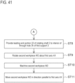
- the method includes a first rotating step of rotating a first workpiece about the first axis with the first workpiece held by the leading end portion of the rotating shaft and supported by the guide bushing, while performing the first rotating step, a first machining step of machining the first workpiece using the tool, a removing step of removing the guide bushing adapter from the through hole, a providing step of moving the rotating shaft in the direction parallel to the first axis to provide the leading end portion of the rotating shaft at an interior of the through hole, a second rotating step of rotating a second workpiece held by the leading end portion of the rotating shaft about the first axis, and while performing the second rotating step, a second machining step of machining the second workpiece using the tool.
- the second machining step is performed while the air is being ejected through the ejection opening toward the leading end portion of the rotating shaft.
- the present invention provides a workpiece support for a machine tool, a machine tool, and a method of using a machine tool.
- the workpiece support, the machine tool, and the method prevent foreign matter from entering a gap between a rotating shaft and a through hole capable of supporting a guide bushing adapter.
- first direction DR1 the direction from a rear end portion 21 of a rotating shaft 2 toward a leading end portion 22 of the rotating shaft 2
- second direction DR2 the direction from the leading end portion 22 of the rotating shaft 2 toward the rear end portion 21 of the rotating shaft 2
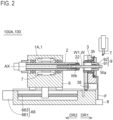
- FIGs. 1 to 13 are cross-sectional views of the machine tool 100A according to the first embodiment, schematically illustrating the machine tool 100A.
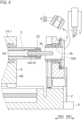
- FIGs. 4 and 5 are cross-sectional views of a part of the machine tool 100A according to the first embodiment, schematically illustrating the part.
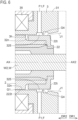
- FIG. 6 is an enlarged view of a region A surrounded by a quadrangular single-dashed line in FIG. 5 .
- FIG. 7 is a cross-sectional view of a part of the machine tool 100A according to the first modification of the first embodiment, schematically illustrating the part.
- FIG. 1 to 3 are cross-sectional views of the machine tool 100A according to the first embodiment, schematically illustrating the machine tool 100A.
- FIGs. 4 and 5 are cross-sectional views of a part of the machine tool 100A according to the first embodiment, schematically illustrating the part.
- FIG. 6 is an enlarged view of a region A surrounded by a quadrangular single-dashed line in FIG. 5 .
- FIG. 8 is an enlarged view of a region B surrounded a quadrangular single-dashed line in FIG. 7 .
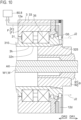
- FIGs. 9 and 10 are cross-sectional views of a part of the machine tool 100A according to a second modification of the first embodiment, schematically illustrating the part. It is to be noted that FIG. 9 illustrates a state after the leading end portion 22 of the rotating shaft 2 has been provided a region in which a guide bushing unit 9 had existed, and that FIG. 10 illustrates a state in which the guide bushing unit 9 is attached to the through hole 3h. It is also to be noted that to avoid complexity of illustration, FIG. 9 only outlines the rotating shaft 2 and a second workpiece W2 using broken lines. FIG.
- FIG. 11 is a cross-sectional view cut along a plane indicated by the arrow C-C in FIG. 9 . It is to be noted that in FIG. 11 , illustration of the rotating shaft 2 and the second workpiece W2 is omitted.
- FIG. 12 illustrates an example of an aid member 315. It is to be noted that FIG. 12 is a view of the aid member 315 as seen in the first direction DR1.
- FIG. 13 schematically illustrates how a valve 88 is provided at an air conduit F.
- the workpiece support 1A according to the first embodiment for a machine tool includes the rotating shaft 2, a first support 3, a second support 6, and an air supplier 8.
- the rotating shaft 2 supports a workpiece (in other words, to-be-worked object) and is rotatable about the first axis AX.
- the rotating shaft 2 has the rear end portion 21 and the leading end portion 22.
- a collet 25 is provided at the leading end portion 22 of the rotating shaft 2.
- the rotating shaft 2 supports the workpiece via the collet 25.
- the first support 3 has a through hole 3h.
- the through hole 3h is capable of supporting a guide bushing unit 9. More specifically, the through hole 3h is capable of supporting a guide bushing adapter 92.
- the guide bushing adapter 92 holds a guide bushing 91. To the through hole 3h, the guide bushing adapter 92 is attachable.
- FIG. 1 illustrates a state before the guide bushing adapter 92 is attached to the through hole 3h of the first support 3.
- FIG. 2 illustrates a state after the guide bushing adapter 92 is attached to the through hole 3h of the first support 3.
- the guide bushing unit 9 is made up of a plurality of members. More specifically, the guide bushing unit 9 includes the guide bushing 91 and the guide bushing adapter 92, which holds the guide bushing 91.
- the guide bushing 91 has a through hole 91h. Through the through hole 91h, the workpiece is inserted.
- the guide bushing 91 is held by the guide bushing adapter 92 by way of fitting, engagement, or any fixing member such as a securing pin.
- the guide bushing adapter 92 is also mounted on the first support 3 by way of fitting, engagement, or any fixing member such as a securing pin.
- a first portion Wa of a workpiece W (more specifically, the leading end portion of the workpiece W) is supported by the guide bushing 91 movably in the first direction DR1 relative to the guide bushing 91.
- a second portion Wb of the workpiece W (more specifically, a longitudinal center portion of the workpiece W or a base end portion of the workpiece W) is held by the rotating shaft 2.
- the second support 6 supports the rotating shaft 2.
- the second support 6 also moves the rotating shaft 2 relative to the first support 3 in a direction parallel to the first axis AX.
- the workpiece W held by the rotating shaft 2 moves in the direction parallel to the first axis AX (see the arrow AR1 illustrated in FIG. 3 ).
- the second support 6 is capable of changing the machining position at which the workpiece W is machined by a tool T.
- the through hole 3h of the first support 3 is capable of receiving the leading end portion 22 of the rotating shaft 2. More specifically, as exemplified in FIG. 4 , the guide bushing unit 9 is removed from the through hole 3h. Then, as exemplified in FIG. 5 , the rotating shaft 2 is moved in the first direction DR1. In this manner, the leading end portion 22 of the rotating shaft 2 is inserted into the through hole 3h.
- the second support 6 is capable of moving the position of the leading end portion 22 of the rotating shaft 2 between a first position (see FIG. 4 ) and a second position (see FIG. 5 ).
- the first position is further at the second direction DR2 side than the through hole 3h of the first support 3.
- the second position is further at the first direction DR1 side than the interior of the through hole 3h or the through hole 3h.
- the first position is an arbitrary position further in the second direction DR2 than an end 3e of the through hole 3h of the first support 3 which end 3e is at the second direction DR2 side.
- the second position is an arbitrary position further in the first direction DR1 than the end 3e of the through hole 3h which end 3e is at the second direction DR2 side.
- the second workpiece W2 held by the leading end portion 22 of the rotating shaft 2 can be machined by the tool T.
- the leading end portion 22 of the rotating shaft 2 is provided further in the second direction DR2 than the guide bushing 91. With this configuration, there is a lower possibility of foreign matter such as chips and coolant attaching to the leading end portion 22 of the rotating shaft 2.
- the position of the leading end portion 22 of the rotating shaft 2 is the second position, which is at the first direction DR1 side. With this configuration, there is a possibility of foreign matter such as chips and coolant attaching to the leading end portion 22 of the rotating shaft 2. As exemplified in FIG.
- the workpiece support 1A for a machine tool includes the air supplier 8, which supplies air to the first support 3.
- an ejection opening 325 is formed on the inner surface 32n (more specifically, the inner circumferential surface) of the through hole 3h of the first support 3. Through the ejection opening 325, the air supplied from the air supplier 8 is ejected (the ejection opening may be simply referred to as "jet").
- the ejection opening 325 may be made up of a groove (for example, a ring-shaped groove formed on the inner surface 32n of the through hole 3h) or may be made up of one ejection opening or a plurality of ejection openings. Alternatively, the ejection opening 325 may be defined by a gap between two members.
- air is ejected through the ejection opening 325 in a direction toward the first axis AX (more specifically, in a direction toward the outer surface 22t of the leading end portion 22 of the rotating shaft 2).
- Air may be ejected through the ejection opening 325 such that the air has a momentum component in the direction toward the first axis AX and a momentum component in the first direction DR1.
- the air ejected through the ejection opening 325 passes through a gap G4 between the inner surface 32n of the through hole 3h and the outer surface 22t of the leading end portion 22 of the rotating shaft 2 and is discharged in the first direction DR1.
- the air discharged in the first direction DR1 through the gap G4 forms a first air curtain J1.
- the first air curtain J1 prevents or restricts entry of foreign matter such as chips and coolant in the gap G4 between the inner surface 32n of the through hole 3h and the outer surface 22t of the leading end portion 22 of the rotating shaft 2. Restricting entry of foreign matter also restricts unintended vibration of the rotating shaft 2, restricting degradation of the machining accuracy. Restricting entry of foreign matter further prevents or restricts damage or breakage of the rotating shaft 2, which would otherwise be caused by entry of foreign matter.
- the through hole 3h of the first support 3 is capable of supporting the guide bushing unit 9. This ensures that the elongate workpiece (in other words, the first workpiece W1) can be stably supported by the leading end portion 22 of the rotating shaft 2 and the guide bushing 91. Also in the workpiece support 1A according to the first embodiment for a machine tool, the through hole 3h of the first support 3 is capable of receiving the leading end portion 22 of the rotating shaft 2. This ensures that the short workpiece (in other words, the second workpiece W2) can be supported by the leading end portion 22 of the rotating shaft 2 inserted in the through hole 3h.
- air can be ejected through the ejection opening 325, which is formed on the inner surface 32n of the through hole 3h, to the gap G4 between the inner surface 32n of the through hole 3h and the outer surface 22t of the leading end portion 22 of the rotating shaft 2.
- the air discharged in the first direction DR1 through the gap G4 prevents or restricts entry of foreign matter such as chips and coolant in the gap G4. As a result, degradation of the machining accuracy is restricted. This restricts damage or breakage of the rotating shaft 2, which would otherwise be caused by entry of foreign matter.
- the machine tool 100A includes, in addition to the workpiece support 1A for a machine tool: a tool holder 110, which holds the tool T; and a second drive 120, which moves the tool holder 110.
- the second drive 120 is capable of moving the tool holder 110 in a direction toward the first axis AX (or in a direction away from the first axis AX).
- the workpiece support 1A for a machine tool includes the second support 6, which supports the rotating shaft 2; a spindle motor 7, which rotates the rotating shaft 2 about the first axis AX; and a first bearing group 41.
- the second support 6 includes a shaft support member 60.
- the shaft support member 60 supports, via the first bearing group 41, the rotating shaft 2 rotatably about the first axis AX.
- the shaft support member 60 is made up of a plurality of members.
- the second support 6 also includes a first drive 66.
- the first drive 66 moves the shaft support member 60 in a direction parallel to the first axis AX.
- the first drive 66 moves the shaft support member 60 in a direction parallel to the first axis AX.
- the first drive 66 is capable of moving the rotating shaft 2, the shaft support member 60, and the spindle motor 7 in a direction parallel to the first axis AX relative to the first support 3.
- the first drive 66 includes a first motor 661 (for example, a servo motor) and a thread axis 663.
- the thread axis 663 is driven by the first motor 661.
- the shaft support member 60 is screwed with the thread axis 663 via a rolling element such as a ball and a roller (more specifically, a block 60b, which is a member of the shaft support member 60, is screwed with the thread axis 663 via a rolling element).
- a rolling element such as a ball and a roller
- the shaft support member 60 screwed with the thread axis 663 moves in a direction parallel to the first axis AX.
- the rotating shaft 2 supported by the shaft support member 60 also moves in a direction parallel to the first axis AX.
- the first drive 66 will not be limited to the drive made up of the first motor 661 and the thread axis 663. As the first drive 66, it is possible to employ any other drive capable of moving the rotating shaft 2 in a direction parallel to the first axis AX.
- the first drive 66 may include the first motor 661 and a rack and pinion. Alternatively, the first drive 66 may include a linear motor.
- the spindle motor 7 rotates the rotating shaft 2 about the first axis AX relative to the shaft support member 60.
- the spindle motor 7 includes a stator 71 and a rotor 72.
- the stator 71 is provided at the shaft support member 60
- the rotor 72 is provided at the rotating shaft 2.
- the spindle motor 7 is a device that electromagnetically rotates the rotating shaft 2.
- the spindle motor 7 may be a device that rotates the rotating shaft 2 using, for example, a transmission belt.
- the first bearing group 41 is provided between the shaft support member 60 and the rotating shaft 2.
- the first bearing group 41 includes a first bearing 41a and a second bearing 41b.
- the first bearing 41a is provided between the shaft support member 60 and the rear end portion 21 of the rotating shaft 2.
- the second bearing 41b is provided between the shaft support member 60 and a center portion 23 of the rotating shaft 2.
- the leading end portion 22 of the rotating shaft 2 protrudes in the first direction DR1 beyond the shaft support member 60. No bearing is provided on the outer surface 22t of the leading end portion 22.
- the first support 3 includes a rotation body 31, a rotation body support member 33, and a second bearing group 35.
- the rotation body 31 is rotatable about a second axis AX2.
- the second axis AX2, which is a rotation axis of the rotation body 31, is substantially coaxial with the first axis AX, which is a rotation axis of the rotating shaft 2.
- the through hole 3h is formed, and the guide bushing adapter 92 is attachable to the through hole 3h.
- the rotation body support member 33 supports, via the second bearing group 35, the rotation body 31 rotatably about the second axis AX2.
- the rotation body support member 33 is made up of a plurality of members.
- the second bearing group 35 is provided between the rotation body support member 33 and the rotation body 31.
- the workpiece support 1A for a machine tool includes a rotary drive 38.
- the rotary drive 38 rotates the rotation body 31 about the second axis AX2 relative to the rotation body support member 33.
- the rotary drive 38 includes a second motor 381 (for example, a servo motor) and a transmission belt 383.
- the transmission belt 383 transmits rotation of an output shaft of the second motor 381 to the rotation body 31.
- the rotary drive 38 will not be limited to the drive made up of the second motor 381 and the transmission belt 383. As the rotary drive 38, it is possible to employ any other drive capable of rotating the rotation body 31 about the second axis AX2.
- the rotary drive 38 may be an electromagnetic drive including a stator and a rotor.
- the rotary drive 38 may alternatively be a device that drives the rotation body 31 using the motive power of the spindle motor 7.
- the rotary drive 38 may include the spindle motor 7 and a transfer mechanism (for example, a transmission belt and a gear) that connects the spindle motor 7 and the rotation body 31 in such a manner that motive power can be transmitted between the spindle motor 7 and the rotation body 31.
- the angular velocity at which the rotation body 31 is rotated by the rotary drive 38 is preferably substantially equal to the angular velocity at which the rotating shaft 2 is rotated by the spindle motor 7.
- the rotation body 31 and the rotating shaft 2 are preferably driven synchronously so that the angular velocities are substantially equal to each other.
- the guide bushing adapter 92 is attached to the through hole 3h of the first support 3. Also in the example illustrated in FIG. 3 , with the guide bushing adapter 92 attached to the first support 3 (more specifically, the through hole 3h), the ejection opening 325 is sealed by the guide bushing adapter 92. In the example illustrated in FIG. 3 , the leading end portion 22 of the rotating shaft 2 is provided further in the second direction DR2 than the guide bushing 91. With this configuration, there is a lower possibility of foreign matter such as chips and coolant attaching to the leading end portion 22 of the rotating shaft 2.
- the workpiece support 1A for a machine tool includes the first support 3, which includes the rotation body 31 and the rotation body support member 33; the air supplier 8; and the air conduit F.
- the through hole 3h is capable of supporting the guide bushing adapter 92, which holds the guide bushing 91 and is formed on the rotation body 31.
- the rotation body 31 is rotatable about a second axis AX2.
- the rotation body support member 33 supports the rotation body 31 rotatably about first axis AX.
- the air supplier 8 includes an air source 80 and a second conduit F2.
- the second conduit F2 fluidally connects the air source 80 and the first support 3 to each other.
- the air source 80 may include a compressor or an air pump.
- the air conduit F fluidally connects the air source 80 and the ejection opening 325 to each other.
- the air conduit F includes a first conduit F1, which is provided in the first support 3, and the second conduit F2, which is provided at an outside of the first support 3.
- the first conduit F1 fluidally connects the air supplier 8 (more specifically, the second conduit F2, which is a part of the air supplier 8) to the ejection opening 325.
- the first conduit F1 is configured to rotate about the second axis AX2 together with the rotation body 31, and the second conduit F2 is provided to be unrotatable about the second axis AX2.
- the first conduit F1 and the second conduit F2 are connected to each other via a revolute joint 326.
- the air conduit F includes the first conduit F1, which is provided in the first support 3, and the second conduit F2, which is provided at the outside of the first support 3.
- the first conduit F1 fluidally connects the air supplier 8 (more specifically, the second conduit F2, which is a part of the air supplier 8) and the ejection opening 325 to each other.
- the first conduit F1 also includes a first subsidiary conduit F11 and a second subsidiary conduit F12.
- the first subsidiary conduit F11 is provided at the rotation body 31, and the second subsidiary conduit F12 is provided at the rotation body support member 33.
- a first end portion 12a (in other words, an upstream end portion) of the second subsidiary conduit F12 is connected to the second conduit F2.
- a second end portion 12b (in other words, a downstream end portion) of the second subsidiary conduit F12 is provided to face a first end portion 11a (in other words, an upstream end portion) of the first subsidiary conduit F11.
- the ejection opening 325 is provided at a second end portion 11b (in other words, a downstream end portion) of the first subsidiary conduit F11.
- the first conduit F1 which fluidally connects the air supplier 8 and the ejection opening 325 to each other, is provided to cross a gap G5 between the rotation body 31 and the rotation body support member 33.
- part of the air flowing through the first conduit F1 passes through the gap G5 between the rotation body 31 and the rotation body support member 33, and is discharged in the first direction DR1.
- the air discharged in the first direction DR1 through the gap G5 forms a second air curtain J2.
- the second air curtain J2 prevents or restricts entry of foreign matter such as chips and coolant in the gap G5 between the rotation body 31 and the rotation body support member 33. Restricting entry of foreign matter in the gap G5 also prevents or restricts damage or breakage of the second bearing group 35, which is provided between the rotation body 31 and the rotation body support member 33.
- the first air curtain J1 is formed by the air discharged from between the inner surface 32n of the through hole 3h and the outer surface 22t of the leading end portion 22 of the rotating shaft 2 (more specifically, the gap G4 between the inner surface 32n and the outer surface 22t), and the second air curtain J2 is formed by the air discharged from between the rotation body 31 and the rotation body support member 33 (more specifically, the gap G5 between the rotation body 31 and the rotation body support member 33).
- the second air curtain J2 is formed to surround the first air curtain J1.
- the air forming the first air curtain J1 passes through a common part of the air conduit F (more specifically, the second subsidiary conduit F12), and the air forming the second air curtain J2 passes through the common part of the air conduit F (more specifically, the second subsidiary conduit F12).
- the configuration of the air conduit F is simplified.
- the air conduit through which the air forming the first air curtain J1 passes may be completely separate from the air conduit through which the air forming the second air curtain J2 passes.
- the first end portion 11a of the first subsidiary conduit F11 is defined by a first ring-shaped groove V1
- the second end portion 12b of the second subsidiary conduit F12 is defined by a second ring-shaped groove V2 (see, if necessary, FIG. 11 for a shape of the first ring-shaped groove V1 and a shape of the second ring-shaped groove V2).
- At least one of the first end portion 11a of the first subsidiary conduit F11 and the second end portion 12b of the second subsidiary conduit F12 may be defined by a ring-shaped groove.
- the second end portion 1 1b of the first subsidiary conduit F11 may be defined by a ring-shaped groove, as exemplified in FIG. 8 , or may be defined by a hole, as exemplified in FIG. 9 .
- the first subsidiary conduit F11 includes at least one through hole 11c (in the example illustrated in FIG. 11 , six through holes 11c).
- the at least one through hole 11c connects the first end portion 11a of the first subsidiary conduit F11 and the second end portion 11b of the first subsidiary conduit F11 to each other.
- the first support 3 (more specifically, the rotation body support member 33) has a drain hole 12d.
- the drain hole 12d fluidally connects the ring-shaped groove (V2) formed on the first support 3 (more specifically, the rotation body support member 33) to the outside of the first support 3.
- the workpiece support 1A for a machine tool (more specifically, the rotation body 31) includes the body 310 of the rotation body 31 and the aid member 315, which is attachable to the body 310.
- the aid member 315 With the aid member 315 attached to the body 310 of the rotation body 31, the aid member 315 constitutes a part of the through hole 3h, which is capable of receiving the leading end portion 22 of the rotating shaft 2.
- the inner surface of the aid member 315 constitutes a part of the inner surface 32n of the through hole 3h.
- the aid member 315 includes a cylinder 316 and a fixed portion 318.
- the cylinder 316 is provided at an interior of the body 310 of the rotation body 31.
- the fixed portion 318 is fixed to the body 310 of the rotation body 31.
- the inner surface of the cylinder 316 constitutes a part of the inner surface of the through hole 3h, which is capable of receiving the leading end portion 22 of the rotating shaft 2.
- the gap G4 between the inner surface of a leading end portion of the through hole 3h and the outer surface 22t of the rotating shaft 2 can be shortened.
- the gap G4 By shortening the gap G4, foreign matter is further more effectively prevented from entering the gap G4, and the first air curtain J1 is efficiently formed.
- gaps through which air is discharged may be formed at both sides of the ejection opening 325 (in other words, at the first direction DR1 side and the second direction DR 2 side).
- the gap formed at the first direction DR1 side is preferably larger than the gap formed at the second direction DR 2 side. In this case, a flow of air in the first direction DR1 is approximately formed.
- an additional air conduit F3 may be formed between the inner surface of the body 310 of the rotation body 31 and the outer surface of the cylinder 316.
- the additional air conduit F3 is provided between the first conduit F1 (more specifically, the first subsidiary conduit F11) and the ejection opening 325, and fluidally connects the first conduit F1 (more specifically, the first subsidiary conduit F11) and the ejection opening 325 to each other.
- the additional air conduit F3 is configured to transmit, in the second direction DR 2, the air received from, for example, the first conduit F1.
- the additional air conduit F3 is defined by, for example, a ring-shaped gap G6 between the inner surface of the body 310 of the rotation body 31 and the outer surface of the cylinder 316 (see, if necessary, FIG. 11 for a shape of the ring-shaped gap G6).
- the ejection opening 325 is defined by a gap between the body 310 of the rotation body 31 and the aid member 315.
- This gap can be referred to as a ring-shaped groove defined by the body 310 of the rotation body 31 and the aid member 315.
- the aid member 315 is defined by the additional air conduit F3
- the first conduit F1 can be simply arranged.
- the ejection opening 325 is defined by the gap between the body 310 of the rotation body 31 and the aid member 315
- the ejection opening 325 can be formed easily. Also, by adjusting the shape of the cylinder 316 of the aid member 315, the position of the ejection opening 325 and/or the size of the ejection opening 325 can be easily adjusted.
- the size of the gap G4 between the inner surface 32n of the through hole 3h and the outer surface 22t of the leading end portion 22 of the rotating shaft 2 can be adjusted by the aid member 315.
- the fixed portion 318 includes a flange 318f.
- the fixed portion 318 (more specifically, the flange 318f) is fixed to the body 310 of the rotation body 31 via a connection member 34 such as a bolt.
- a connection member 34 such as a bolt.
- a through hole 318h is formed in the fixed portion 318. In the through hole 318h, the connection member 34 such as a bolt is inserted.
- one of the aid member 315 and the guide bushing adapter 92 is selectively attachable to the body 310 of the rotation body 31.
- the guide bushing adapter 92 in the state in which the aid member 315 is attached to the body 310 of the rotation body 31, the guide bushing adapter 92 is not attachable to the body 310; and as exemplified in FIG. 10 , in the state in which the guide bushing adapter 92 is attached to the body 310 of the rotation body 31, the aid member 315 is not attachable to the body 310.
- the other of the aid member 315 and the guide bushing adapter 92 is removed from the body 310 in advance.
- the ejection opening 325 is sealed by the guide bushing adapter 92.
- the air supplier 8 includes the valve 88, which is provided at the air conduit F (more specifically, the second conduit F2).
- the valve 88 opens and closes the air conduit F.
- An example of the valve 88 is an electromagnetically driven solenoid valve.
- the machine tool 100A includes a controller 130.
- the controller 130 controls the valve 88.
- the controller 130 may control the first drive 66, the spindle motor 7, the rotary drive 38, the air source 80, and the second drive 120.
- the controller 130 switches the state of the valve 88 from closed state to open state.
- the first air curtain J1 is formed by the air supplied to pass through the valve 88 (or the first air curtain J1 and the second air curtain J2 are formed).
- the second air curtain J2 is formed by the air supplied to pass through the valve 88.
- FIG. 14 is a cross-sectional view of the machine tool 100B according to the second embodiment, schematically illustrating the machine tool 100B.
- FIGs. 15 and 16 are cross-sectional views of the machine tool 100B according to the second embodiment, schematically illustrating the machine tool 100B.
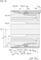
- FIGs. 17 and 18 are enlarged views of a region D surrounded a quadrangular single-dashed line in FIG. 16 . It is to be noted that FIG. 18 illustrates a state after an attachment 51 illustrated in FIG. 17 has been displaced in a direction away from the first axis AX.
- FIG. 19 illustrates an example of the attachment 51.
- FIG. 20 is a cross-sectional view cut along a plane indicated by the arrow E-E in FIG. 19 .
- FIG. 21 illustrates another example of the attachment 51.
- FIG. 22 is a cross-sectional view cut along a plane indicated by the arrow H-H in FIG. 21 .
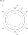
- FIG. 23 schematically illustrates an example of a nut 28.
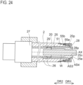
- FIG. 24 is a cross-sectional view of a part of the machine tool 100B according to the second embodiment, schematically illustrating the part.
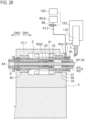
- FIG. 25 is a cross-sectional view of the machine tool 100B according to the second embodiment, schematically illustrating the machine tool 100B.
- FIG. 26 is an enlarged view of a region N surrounded a quadrangular single-dashed line in FIG. 25 .
- the workpiece support 1B according to the second embodiment for a machine tool and the machine tool 100B according to the second embodiment are respectively different from the workpiece support 1A according to the first embodiment for a machine tool and the machine tool 100A according to the first embodiment in that in the second embodiment, the attachment 51 is provided in contact with the outer surface 22t of the leading end portion 22 of the rotating shaft 2.
- the workpiece support 1B includes (1) the rotating shaft 2, which supports a workpiece and is rotatable about the first axis AX; (2) the first support 3, which includes the through hole 3h, which is capable of supporting the guide bushing adapter 92, which holds the guide bushing 91, the first support 3 being capable of receiving the leading end portion 22 of the rotating shaft 2 in the through hole 3h; (3) the second support 6, which supports the rotating shaft 2 and moves the rotating shaft 2 in a direction parallel to the first axis AX relative to the first support 3; and (4) the air supplier 8, which supplies air to the first support 3.
- the ejection opening 325 through which the air supplied from the air supplier 8 is ejected, is formed on the inner surface (more specifically, the inner circumferential surface) of the through hole 3h of the first support 3.
- the machine tool 100B according to the second embodiment also includes, in addition to the workpiece support 1B: the tool holder 110, which holds the tool T; and the second drive 120, which moves the tool holder 110.
- the second drive 120 is capable of moving the tool holder 110 in a direction toward the first axis AX (or in a direction away from the first axis AX).
- the second workpiece W2 held by the leading end portion 22 of the rotating shaft 2 can be machined by the tool T.
- FIG. 6 when the position of the leading end portion 22 of the rotating shaft 2 is at the interior of the through hole 3h, there is a gap G1 between an outermost surface 222t of the leading end portion 22 and an inner surface 32n of the through hole 3h. Due to the presence of the gap G1, the degree of bending of the rotating shaft 2 increases when the tool T applies a great machining load on the second workpiece W2.
- the workpiece support 1B according to the second embodiment for a machine tool includes the attachment 51, which is provided in contact with the outer surface 22t of the leading end portion 22 of the rotating shaft 2.
- the attachment 51 is attached to the leading end portion 22 of the rotating shaft 2. It is to be noted that in this specification, the attachment 51 provided in contact with the outer surface 22t of the leading end portion 22 of the rotating shaft 2 may be referred to as "first attachment”.
- At least a part of the attachment 51 is displaceable in a direction away from the first axis AX.
- the configuration in which at least a part of the attachment 51 is displaceable in a direction away from the first axis AX reduces a gap G2 between an outer surface 51t of the attachment 51 and the inner surface 32n of the through hole 3h (see FIG. 18 ).
- the attachment 51 reduces the amount of displaceability of the leading end portion 22 of the rotating shaft 2 in a direction perpendicular to the first axis AX.
- the attachment 51 is displaceable in a direction away from the first axis AX so that a first distance L1 is larger than a second distance L2.
- the first distance L1 is a distance between the first axis AX and an outermost portion 511t of the attachment 51, which is provided in contact with the outer surface 22t of the leading end portion 22 (in the example illustrated in FIG. 18 , the outermost portion 5 11t of the attachment 51 is the outer surface 51t of the attachment 51).
- the second distance L2 is a distance between the first axis AX and the outermost surface 222t of the leading end portion 22 of the rotating shaft 2.
- the outermost portion 511t of the attachment 51 is intended to mean a portion, among the portions of the attachment 51, that is largest in distance from the first axis AX. It is also to be noted that the outermost surface 222t of the leading end portion 22 of the rotating shaft 2 is intended to mean a portion, among the portions of the outer surface of the leading end portion 22 of the rotating shaft 2, that is largest in distance from the first axis AX.
- the configuration in which the first distance L1 is larger than the second distance L2 enables the attachment 51 to prevent direct contact between the outermost surface 222t of the leading end portion 22 of the rotating shaft 2 and the inner surface 32n of the through hole 3h.
- the outermost portion 511t of the attachment 51 contacts the inner surface 32n of the through hole 3h before the outermost surface 222t of the leading end portion 22 of the rotating shaft 2 contacts the inner surface 32n of the through hole 3h.
- the amount of displaceability of the leading end portion 22 in the direction perpendicular to the first axis AX is reduced.
- the through hole 3h of the first support 3 is capable of supporting the guide bushing unit 9. This ensures that the elongate workpiece (in other words, the first workpiece W1) can be stably supported by the leading end portion 22 of the rotating shaft 2 and the guide bushing 91. Also in the workpiece support 1B according to the second embodiment for a machine tool, as exemplified in FIG. 16 , the through hole 3h of the first support 3 is capable of receiving the leading end portion 22 of the rotating shaft 2.
- the workpiece support 1B includes the attachment 51, which is provided in contact with the outer surface 22t of the leading end portion 22 of the rotating shaft 2.
- the attachment 51 prevents direct contact between the outermost surface 222t of the leading end portion 22 of the rotating shaft 2 and the inner surface 32n of the through hole 3h. In this manner, bending of the rotating shaft 2 is restricted when the tool T applies a machining load on the second workpiece W2.
- bending of the rotating shaft 2 is restricted, ensuring that the machining accuracy of the second workpiece W2 is stably maintained.
- the attachment 51 is provided between the outer surface 22t of the rotating shaft 2 and the inner surface 32n of the through hole 3h.
- the attachment 51 has an inner surface 51n, which is in contact with the outer surface 22t of the rotating shaft 2, and the outer surface 5 1t, which faces the inner surface 32n of the through hole 3h.
- a small gap G2 is preferably formed between the outer surface 51t of the attachment 51 and the inner surface 32n of the through hole 3h. It is to be noted, however, that in a case where the contact between the outer surface 51t of the attachment 51 and the inner surface 32n of the through hole 3h does not interfere with the movement of the rotating shaft 2 in the direction parallel to the first axis AX, the gap G2 between the outer surface 51t and the inner surface 32n may be zero.
- the outer surface 51t and the inner surface 32n may be turned into a pre-load applied state.
- the state of the attachment 51 which is provided at the leading end portion 22 of the rotating shaft 2, is changeable from a first state (see FIG. 17 ) to a second state (see FIG. 18 ).
- the first state is a state in which the first distance L1 between the first axis AX and the outermost portion 511t of the attachment 51 is equal to or smaller than the second distance L2 between the first axis AX and the outermost surface 222t of the leading end portion 22 of the rotating shaft 2.
- the second state is a state in which the first distance L1 between the first axis AX and the outermost portion 511t of the attachment 51 is larger than the second distance L2 between the first axis AX and the outermost surface 222t of the leading end portion 22 of the rotating shaft 2.
- the configuration in which the first state (see FIG. 17 ) can be realized is not essential.
- At least one of the attachment 51 and the rotating shaft 2 has an inclined surface AS.
- the inclined surface AS converts the movement of the attachment 51 in a direction parallel to the first axis AX relative to the rotating shaft 2 into a displacement of at least a part of the attachment 51 (for example, the outer surface 51t of the attachment 51) in a direction away from the first axis AX.
- the gap G2 between the outer surface 51t of the attachment 51 and the inner surface 32n of the through hole 3h reduces.
- the amount of displaceability of the leading end portion 22 of the rotating shaft 2 in the direction perpendicular to the first axis AX reduces.
- the attachment 51 has a wedge shape in a cross-section including the first axis AX. More specifically, an end portion of the attachment 51 at the second direction DR2 side has a wedge shape that becomes smaller in thickness in the second direction DR2.
- the inner surface 51n of the attachment 51 has a first inclined surface AS1
- the outer surface 22t of the rotating shaft 2 has a second inclined surface AS2.
- the second inclined surface AS2 is in contact with the first inclined surface AS 1.
- the first inclined surface AS 1 is an inclined surface that increases in distance from the first axis AX in the second direction DR2.
- the second inclined surface AS2 is also an inclined surface that increases in distance from the first axis AX in the second direction DR2.
- the attachment 51 by moving the attachment 51 in the second direction DR2 relative to the rotating shaft 2, at least a part of the attachment 51 (for example, the outer surface 51t of the attachment 51) is displaced in a direction away from the first axis AX.
- a rolling element such as a ball and a roller or an elastic element such as an O-ring at one of the inner surface 51n of the attachment 51 and the outer surface 22t of the rotating shaft 2, the inner surface 51n and the outer surface 22t may be turned into a pre-load applied state.
- At least a part of the attachment 51 is enlargeable in diameter in a direction away from the first axis AX. More specifically, at least a part of the attachment 51, which is provided at the leading end portion 22 of the rotating shaft 2, is enlargeable in diameter in a direction away from the first axis AX so that the first distance L1 between the first axis AX and the outermost portion 511t of the attachment 51 is larger than the second distance L2 between the first axis AX and the outermost surface 222t of the leading end portion 22 of the rotating shaft 2.
- FIG. 18 illustrates a state in which at least a part of the attachment 51 is enlarged in diameter in a direction away from the first axis AX.
- the attachment 51 has a first shape.
- the first shape is a shape elastically deformed from a default shape of the attachment 51.
- the gap G2 between the outer surface 51t of the attachment 51 and the inner surface 32n of the through hole 3h can be easily adjusted. It is to be noted that at least a part of the attachment 51 may be enlarged in diameter after the attachment 51 has been inserted into the through hole 3h or before the attachment 51 is inserted into the through hole 3h.
- At least a part of the attachment 51 is diminishable in diameter in a direction toward the first axis AX.
- at least a part of the attachment 51 is diminishable in diameter in a direction toward the first axis AX so that the first distance L1 between the first axis AX and the outermost portion 511t of the attachment 51 is equal to or smaller than the second distance L2 between the first axis AX and the outermost surface 222t of the leading end portion 22 of the rotating shaft 2.
- FIG. 17 illustrates a state in which at least a part of the attachment 51 is diminished in diameter in a direction toward the first axis AX.
- the attachment 51 has a substantially stress free, default shape or has a second shape, which is smaller in the degree of elastic deformation from the default shape than the first shape.
- the attachment 51 includes, for example, a ring member.
- the term ring member encompasses a ring member having a cut (for example, a C-shaped ring member), a circular ring member, and a ring member made up of a plurality of ring divisions.
- the attachment 51 has a ring member 51A.
- the ring member 51A has a C-shape in a view from a direction along the first axis AX.
- the ring member 51A has a cut 51r. In this case, a whole of the ring member 51A can be easily enlarged in diameter in a direction away from the first axis AX.
- the attachment 51 may be a ring member 51B.
- the ring member 51B has a circular shape in a view from a direction along the first axis AX.
- the circular ring member 51B includes a circular ring body 515 and a plurality of legs 516.
- the plurality of legs 516 extend in a direction along the first axis AX from the ring body 515.
- a gap G3 is formed between adjacent two legs 516.
- a part of the ring member 51B (more specifically, the plurality of legs 516) can be easily enlarged in diameter in a direction away from the first axis AX.
- the attachment 51 is made up of a single ring member.
- the attachment 51 may be made up of a plurality of ring divisions.
- grooves to hold the ring divisions or similar functioning members may be formed on the outer surface 22t of the rotating shaft 2 to prevent removal of the ring divisions from the outer surface 22t of the rotating shaft 2.
- the workpiece support 1B for a machine tool includes the pressing member 55, which presses the attachment 51 in the second direction DR2.
- the pressing member 55 moves the attachment 51 in a direction parallel to the first axis AX (more specifically, the second direction DR2 ) relative to the rotating shaft 2.
- the outer surface 51t of the attachment 51 is displaced in a direction toward the inner surface 32n of the through hole 3h (see FIG. 18 ).
- the gap G2 between the outer surface 51t of the attachment 51 and the inner surface 32n of the through hole 3h reduces.
- the pressing member 55 includes a first thread portion 551.
- the first thread portion 551 converts the rotational force acting on the pressing member 55 into a pressing force to press the attachment 51.
- the pressing member 55 includes a threaded member 55a.
- the threaded member 55a converts the rotational force acting on the pressing member 55 into a pressing force to press the attachment 51.
- the threaded member 55a is screwed with a second thread portion 28m of a member of the rotating shaft 2 (for example, the nut 28, which is screwed with a rotating shaft body 20).
- the threaded member 55a is a bolt having a recess 552.
- the recess 552 is engageable with a tool K, such as a wrench and a driver.
- the threaded member 55a may be the nut 28 (more specifically, a cap nut), which is screwed with the rotating shaft body 20.
- the pressing member 55 is made up of a plurality of members, and the pressing member 55 includes a cylindrical collar 55b.
- the cylindrical collar 55b is provided between the threaded member 55a and the attachment 51.
- the threaded member 55a presses the attachment 51 in the second direction DR2 via the collar 55b.
- the collar 55b may be omitted. In other words, the threaded member 55a may directly press the attachment 51 in the second direction DR2 .
- the workpiece support 1B for a machine tool includes the nut 28 (more specifically, a cap nut), which prevents removal of the attachment 51 from the rotating shaft 2.
- the nut 28 is attached to a leading end portion of the rotating shaft body 20. In this manner, the nut 28 prevents movement of the attachment 51 in the first direction DR1 beyond the nut 28.
- the nut 28 includes a female thread portion 28p. The female thread portion 28p is screwed with a male thread portion 20p of the rotating shaft body 20.
- the nut 28 includes a threaded hole 28h.
- the threaded member 55a is inserted.
- the threaded member 55a is moved in the second direction DR2 .
- the threaded member 55a presses the attachment 51 in the second direction DR2 via the collar 55b.
- the outer surface 51t of the attachment 51 is displaced in a direction away from the first axis AX.
- the nut 28 has six threaded holes 28h, and six threaded members 55a can be provided in the respective six threaded holes. It is to be noted that the number of threaded holes 28h of the nut 28 will not be limited to six; any other number of threaded holes 28h may be provided. In the example illustrated in FIG. 23 , the plurality of the threaded holes 28h are provided at equal angular intervals around the center axis of the nut 28.
- the rotating shaft 2 includes the rotating shaft body 20 and the collet 25, which holds the workpiece W.
- the rotating shaft 2 may include a collet operation shaft 26, an operation shaft drive 27, and/or the nut 28 (more specifically, a cap nut).
- the rotating shaft body 20 is a cylindrical member.
- the rotating shaft body 20 may be made up of a single member or may be made up of an assembly of a plurality of members.
- the collet 25 and the collet operation shaft 26 are provided at an interior of the rotating shaft body 20, and the attachment 51 is provided at an outside of the rotating shaft body 20.
- the collet 25 has an inner surface 25n, which holds the workpiece W, and an inclined surface pressed by the collet operation shaft 26 (this inclined surface will be hereinafter referred to as "third inclined surface AS3").
- the nut 28 includes the female thread portion 28p, which is screwed with the male thread portion 20p of the rotating shaft body 20.
- the nut 28 prevents removal of the collet 25 from the rotating shaft body 20.
- the nut 28 also prevents removal of the attachment 51 and/or the collar 55b from the rotating shaft body 20. In other words, attaching the nut 28 to the rotating shaft body 20 prevents both removal of the collet 25 from the rotating shaft body 20 and removal of the attachment 51 from the rotating shaft body 20.
- the collet operation shaft 26 has an inclined surface capable of pressing the third inclined surface AS3 of the collet 25 (this inclined surface will be hereinafter referred to as "fourth inclined surface AS4").
- fourth inclined surface AS4 of the collet operation shaft 26 presses the third inclined surface AS3 of the collet 25.
- the inner surface 25n of the collet 25 is displaced in a direction toward the first axis AX, and the workpiece W is held by the inner surface 25n of the collet 25.
- the second support 6 moves the rotating shaft 2 in the first direction DR1 with the collet 25 holding the workpiece W, the workpiece W moves in the first direction DR1 together with the rotating shaft 2.
- the second support 6 is capable of changing the machining position at which the workpiece W is machined by the tool T.
- the leading end portion of the workpiece W that has been subjected to a predetermined type of machining may be separated from the rest of the workpiece W by cutting.
- the operation shaft drive 27 moves the collet operation shaft 26 in the first direction DR1.
- the operation shaft drive 27 may include a fluid pressure cylinder such as a hydraulic cylinder and an air cylinder, and/or may include a motor. Additionally, the operation shaft drive 27 may be capable of moving the collet operation shaft 26 in the second direction DR2 .
- the rotating shaft 2 includes an urging member 29 (for example, a spring) to urge the collet operation shaft 26 in the second direction DR2
- the collet operation shaft 26 may be moved in the second direction DR2 utilizing the urging force of the urging member 29.
- the leading end portion 22 of the rotating shaft 2 is movable from an outside of the through hole 3h (see FIG. 15 ) to the interior of the through hole 3h (see FIG. 16 ).
- the second support 6 changes the position of the leading end portion 22 attached with the attachment 51 from the first position to the second position.
- the first position is further in the second direction DR2 than the end 3e of the through hole 3h of the first support 3 which end 3e is at the second direction DR2 side.
- the second position is further in the first direction DR1 than the end 3e of the through hole 3h which end 3e is at the second direction DR2 side.
- leading end portion 22 of the rotating shaft 2 is movable to the interior of the through hole 3h with the attachment 51 attached to the leading end portion 22 of the rotating shaft 2, it is not necessary to attach the attachment 51 to the leading end portion 22 of the rotating shaft 2 after the leading end portion 22 has been moved to the interior of the through hole 3h. This reduces the amount of work necessary for switching from machining of an elongate workpiece to machining of a short workpiece, and quickens the switch from machining of an elongate workpiece to machining of a short workpiece.
- the first workpiece W 1 (in other words, an elongate workpiece) can be supported by both the leading end portion 22 of the rotating shaft 2 and the guide bushing 91.
- the attachment 51 it is not necessary to remove the attachment 51 from the rotating shaft 2 at the time of machining of the elongate workpiece. This reduces the possibility of the attachment 51 being lost.
- the amount of work necessary for switching from machining of a short workpiece to machining of an elongate workpiece reduces. This quickens the switch from machining of a short workpiece to machining of an elongate workpiece.
- the attachment 51 is attached to the leading end portion 22 of the rotating shaft 2 in both cases where the position of the leading end portion 22 of the rotating shaft 2 is the first position (see FIG. 15 ) and where the position of the leading end portion 22 is the second position (see FIG. 16 ).
- the attachment 51 may be removed from the leading end portion 22 of the rotating shaft 2, and at the time of machining of a short workpiece, the attachment 51 may be attached to the leading end portion 22 of the rotating shaft 2.
- the tapered inner surface 321n increases in distance from the first axis AX in the second direction DR2. In this case, at the time of inserting the leading end portion 22 into the through hole 3h, catching of the attachment 51 by the end 3e of the through hole 3h which end 3e is at the second direction DR2 side is prevented or restricted further more effectively.
- the leading end portion 22 of the rotating shaft 2 is permitted to slide relative to the through hole 3h of the first support 3 with the attachment 51 attached to the leading end portion 22 of the rotating shaft 2 (more specifically, in a state in which the first distance L1 between the first axis AX and the outermost portion 511t of the attachment 51 is larger than the second distance L2 between the first axis AX and the outermost surface 222t of the leading end portion 22 of the rotating shaft 2).
- the second support 6 in a state in which the amount of displaceability of the leading end portion 22 of the rotating shaft 2 in a direction perpendicular to the first axis AX is restricted by the attachment 51, the second support 6 is capable of moving the rotating shaft 2 in a direction parallel to the first axis AX relative to the first support 3 (see the arrow AR2 illustrated in FIG. 25 ).
- This enables the second workpiece W2 to be machined by the tool T with bending of the second workpiece W2 restricted, and enables the machining position of the second workpiece W2 to be changed by moving the second workpiece W2 in the direction parallel to the first axis AX.
- the workpiece support 1B for a machine tool includes the air supplier 8, which supplies air to the first support 3; the ejection opening 325, through which air is ejected; and the air conduit F.
- the ejection opening 325 through which the air supplied from the air supplier 8 is ejected, is formed on the inner surface 32n (more specifically, the inner circumferential surface) of the through hole 3h of the first support 3.
- the ejection opening 325 may be made up of a groove (for example, a ring-shaped groove formed on the inner surface 32n of the through hole 3h) or may be made up of one ejection opening or a plurality of ejection openings.
- the ejection opening 325 may be defined by a gap between two members.
- air is ejected through the ejection opening 325 in a direction toward the first axis AX (more specifically, in a direction toward the outer surface 22t of the leading end portion 22 of the rotating shaft 2).
- Air may be ejected through the ejection opening 325 such that the air has a momentum component in the direction toward the first axis AX and a momentum component in the first direction DR1.
- the air injected through the ejection opening 325 passes through the gap G4 between the inner surface 32n of the through hole 3h and the outer surface 22t of the leading end portion 22 of the rotating shaft 2 and is discharged in the first direction DR1.
- the air discharged in the first direction DR1 through the gap G4 forms the first air curtain J1.
- the first air curtain J1 prevents or restricts entry of foreign matter such as chips and coolant in the gap G4 between the inner surface 32n of the through hole 3h and the outer surface 22t of the leading end portion 22 of the rotating shaft 2.
- the attachment 51 is provided at the leading end portion 22 of the rotating shaft 2.
- the attachment 51 restricts a leakage of the air ejected through the ejection opening 325 to the second direction DR 2 side.
- the first air curtain J1 can be efficiently formed.
- the first conduit F1 which fluidally connects the air supplier 8 and the ejection opening 325 to each other, is provided to cross the gap G5 between the rotation body 31 and the rotation body support member 33.
- part of the air flowing through the first conduit F1 passes through the gap G5 between the rotation body 31 and the rotation body support member 33, and is discharged in the first direction DR1.
- the second air curtain J2, which is formed by the air discharged from the gap G5 in the first direction DR1 prevents or restricts entry of foreign matter such as chips and coolant in the gap G5 between the rotation body 31 and the rotation body support member 33.
- the air conduit F is similar in configuration to the air conduit F according to the second modification (see FIG. 9 ) of the first embodiment.
- the air conduit may have the configuration of the air conduit F according to the first embodiment (see FIG. 6 ), the configuration of the air conduit F according to the first modification (see FIG. 8 ) of the first embodiment, or any other air conduit configuration.
- the guide bushing adapter 92 is attached to the through hole 3h. Also in the example illustrated in FIG. 14 , with the guide bushing adapter 92 attached to the through hole 3h, the ejection opening 325 is sealed by the guide bushing adapter 92.
- This configuration in the example illustrated in FIG. 14 ensures that the second air curtain J2 can be efficiently formed by the air discharged in the first direction DR1 through the gap between the rotation body 31 and the rotation body support member 33.
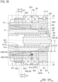
- FIG. 27 is a cross-sectional view of the machine tool 100C according to the third embodiment, schematically illustrating the machine tool 100C.
- FIG. 28 is a cross-sectional view of a part of the machine tool 100C according to the third embodiment, schematically illustrating the part.
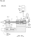
- FIG. 29 is a cross-sectional view of the machine tool 100C according to the third embodiment, schematically illustrating the machine tool 100C.
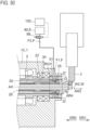
- FIG. 30 is a cross-sectional view of a part of the machine tool 100C according to the third embodiment, schematically illustrating the part.
- FIG. 31 is an enlarged view of a region Q surrounded a quadrangular single-dashed line in FIG. 30 .
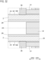
- FIG. 32 is an enlarged view of a region P surrounded a quadrangular single-dashed line in FIG. 28 .
- the third embodiment is different from the first embodiment and the second embodiment in that the spindle motor 7, which rotates the rotating shaft 2 about the first axis AX, is provided at the first support 3 in the third embodiment.
- the workpiece support 1C according to the third embodiment for a machine tool includes the rotating shaft 2, the first support 3, the second support 6, and the air supplier 8.
- the workpiece support 1C for a machine tool may include the attachment 51.
- the rotating shaft 2 supports the workpiece W and is rotatable about the first axis AX.
- the rotating shaft 2 has the rear end portion 21 and the leading end portion 22.
- the collet 25 is provided at the leading end portion 22 of the rotating shaft 2.
- the rotating shaft 2 supports the workpiece via the collet 25.
- the first support 3 has the through hole 3h, which is capable of supporting the guide bushing unit 9. More specifically, the through hole 3h is capable of supporting the guide bushing adapter 92, which holds the guide bushing 91. To the through hole 3h, the guide bushing adapter 92 is attachable.
- FIG. 28 illustrates a state in which the guide bushing adapter 92 is attached to the through hole 3h of the first support 3.
- FIG. 29 illustrates a state in which the guide bushing adapter 92 is removed from the through hole 3h of the first support 3.
- the guide bushing unit 9 is made up of a plurality of members. More specifically, the guide bushing unit 9 includes the guide bushing 91 and the guide bushing adapter 92, which holds the guide bushing 91.
- the guide bushing 91 has the through hole 91h, through which the workpiece is inserted.
- the guide bushing 91 is held by the guide bushing adapter 92.
- the guide bushing adapter 92 is mounted on the first support 3.
- the first portion Wa of the workpiece W (more specifically, the leading end portion of the workpiece W) is supported by the guide bushing 91 movably in the first direction DR1 relative to the guide bushing 91.
- the second portion Wb of the workpiece W (more specifically, the longitudinal center portion of the workpiece W or the base end portion of the workpiece W) is held by the rotating shaft 2.
- the second support 6 supports the rotating shaft 2 (more specifically, a part of the rotating shaft 2).
- the second support 6 also moves the rotating shaft 2 relative to the first support 3 in a direction parallel to the first axis AX.
- the workpiece W held by the rotating shaft 2 moves in the direction parallel to the first axis AX (see the arrow AR1).
- the second support 6 is capable of changing the machining position at which the workpiece W is machined by the tool T.
- the guide bushing 91 is provided at the first region RG1 of the interior of the through hole 3h, and the leading end portion 22 of the rotating shaft 2 is provided at a second region RG2 of the interior of the through hole 3h.
- the second region RG2 is a region further at the second direction DR2 side than the first region RG1.
- the first workpiece W1 can be supported by the guide bushing 91, which is provided at the first region RG1 of the interior of the through hole 3h of the first support 3, and by the leading end portion 22 of the rotating shaft 2, which is provided at the second region RG2 of the interior of the through hole 3h.
- both the leading end portion 22 of the rotating shaft 2 and the guide bushing 91 are provided at the single through hole 3h makes the first workpiece W1 less likely to bend. It is to be noted, however, that the third embodiment does not exclude an embodiment in which the leading end portion 22 of the rotating shaft 2 is provided at the outside of the through hole 3h (more specifically, an embodiment in which the leading end portion 22 is provided further at the second direction DR2 side than the through hole 3h).
- the through hole 3h of the first support 3 is capable of receiving the leading end portion 22 of the rotating shaft 2.
- the state of the interior of the through hole 3h is switchable between a first state (see FIG. 28 ) and a second state (see FIG. 30 ).
- the first state is a state in which the guide bushing 91 is provided at a first region RG1 of the interior of the through hole 3h.
- the second state is a state in which the leading end portion 22 of the rotating shaft 2 is provided at the first region RG1. Switching the state of the interior of the through hole 3h from the first state to the second state is performed by removing the guide bushing adapter 92 from the through hole 3h and then moving the rotating shaft 2 in the first direction DR1.
- the second support 6 is capable of changing the position of the leading end portion 22 of the rotating shaft 2 from a position further at the second direction DR2 side than the first region RG1 to a position in the first region RG1 that has been occupied by the guide bushing unit 9.
- a short workpiece (in other words, the second workpiece W2) held by the leading end portion 22 of the rotating shaft 2 can be machined by the tool T.
- the workpiece support 1C according to the third embodiment for a machine tool includes the air supplier 8, which supplies air to the first support 3.
- the ejection opening 325 is formed on the inner surface 32n (more specifically, the inner circumferential surface) of the through hole 3h of the first support 3. Through the ejection opening 325, the air supplied from the air supplier 8 is ejected.
- the workpiece support 1C according to the third embodiment for a machine tool provides effects similar to the effects provided by the workpiece support 1A according to the first embodiment for a machine tool.
- the ejection opening 325 may be made up of a groove (for example, a ring-shaped groove formed on the inner surface 32n of the through hole 3h) or may be made up of one ejection opening or a plurality of ejection openings. Alternatively, the ejection opening 325 may be defined by a gap between two members.
- the air conduit F which fluidally connects the air source 80 and the ejection opening 325 to each other, may have the configuration of the air conduit F according to the first embodiment (see FIG. 6 ), the configuration of the air conduit F according to the first modification (see FIG. 8 ) of the first embodiment, the configuration of the air conduit F according to the second modification (see FIG. 9 ) of the first embodiment, or any other air conduit configuration.
- the machine tool 100C includes, in addition to the workpiece support 1C for a machine tool: the tool holder 110, which holds the tool T; and the second drive 120, which moves the tool holder 110.
- the second drive 120 is capable of moving the tool holder 110 in a direction toward the first axis AX (or in a direction away from the first axis AX).
- the second support 6 includes the shaft support member 60 and the first drive 66.
- the workpiece support 1C for a machine tool includes the first bearing group 41.
- the shaft support member 60 supports, via the first bearing group 41, the rotating shaft 2 rotatably about the first axis AX.
- the shaft support member 60 is made up of a plurality of members.
- the first drive 66 moves the shaft support member 60 in a direction parallel to the first axis AX.
- the rotating shaft 2 supported by the shaft support member 60 moves in the direction parallel to the first axis AX.
- the first drive 66 is capable of moving the rotating shaft 2 and the shaft support member 60 in a direction parallel to the first axis AX relative to the first support 3 and the spindle motor 7.
- the first drive 66 includes the first motor 661 (for example, a servo motor) and the thread axis 663, which is driven by the first motor 661.
- the shaft support member 60 is screwed with the thread axis 663 via a rolling element such as a ball and a roller.
- a rolling element such as a ball and a roller.
- the first drive 66 will not be limited to the drive made up of the first motor 661 and the thread axis 663.
- the first bearing group 41 is provided between the shaft support member 60 and the rotating shaft 2.
- the first bearing group 41 includes the first bearing 41a, which is provided between the shaft support member 60 and the rear end portion 21 of the rotating shaft 2.
- the center portion 23 and the leading end portion 22 of the rotating shaft 2 protrude in the first direction DR1 beyond the shaft support member 60.
- the first support 3 includes the rotation body 31, the rotation body support member 33, and the second bearing group 35. Also in the example illustrated in FIG. 27 , the first support 3 includes the spindle motor 7 and an engagement member 36.
- the rotation body 31 is rotatable about the second axis AX2, which is substantially coaxial with the first axis AX.
- the rotation axis of the rotation body 31 is substantially coaxial with the rotation axis of the rotating shaft 2.
- the through hole 3h is formed, and the guide bushing adapter 92 is attachable to the through hole 3h.
- the rotation body support member 33 supports, via the second bearing group 35, the rotation body 31 rotatably about the second axis AX2.
- the rotation body support member 33 is made up of a plurality of members.
- the second bearing group 35 is provided between the rotation body support member 33 and the rotation body 31.
- the spindle motor 7 rotates the rotating shaft 2 about the first axis AX relative to the shaft support member 60.
- the spindle motor 7 includes a stator 71 and a rotor 72.
- the stator 71 is provided at the rotation body support member 33, and the rotor 72 is provided at the rotation body 31.
- the rotation body 31 is electromagnetically driven into rotation by the spindle motor 7.
- the spindle motor 7 may drive the rotation body 31 into rotation via a motive power transmission member such as a transmission belt.
- the engagement member 36 is provided at the rotation body 31, and the engagement member 36 transmits a rotation of the rotation body 31 to the rotating shaft 2.
- the engagement between the engagement member 36 and an engagement portion 24 of the rotating shaft 2 permits the rotating shaft 2 to move in a direction parallel to the first axis AX relative to the rotation body 31, and prohibits rotation of the rotating shaft 2 about the first axis AX relative to the rotation body 31.
- one of the engagement portion 24 and the engagement member 36 may include at least one groove M1, which extends in a direction parallel to the first axis AX, or may include at least one elongate hole extending in the direction parallel to the first axis AX.
- the other of the engagement portion 24 and the engagement member 36 may include at least one protrusion M2, which is engaged with the at least one groove M1 or the at least one elongate hole.
- the workpiece support 1A for a machine tool includes the rotary drive 38.
- the rotary drive 38 rotates the rotation body 31 about the second axis AX2, which is substantially coaxial with the first axis AX, relative to the rotation body support member 33.
- the rotary drive 38 which rotates the rotation body 31 about the second axis AX2 relative to the rotation body support member 33, is made up of the spindle motor 7.
- the spindle motor 7 serves as the rotary drive 38, which rotates the rotation body 31 about the second axis AX2.
- the configuration in which the spindle motor 7 and the rotary drive 38 are commonized ensures compactness for the mechanism to drive the rotating shaft 2 and the rotation body 31 into rotation. Also, in a case of commonizing the spindle motor 7, which drives the rotating shaft 2 into rotation, and the rotary drive 38, which drives the rotation body 31 into rotation, the rotation of the rotating shaft 2 and the rotation of the rotation body 31 can be easily synchronized.
- the workpiece support 1C for a machine tool includes the attachment 51, which is provided in contact with the outer surface 22t of the leading end portion 22 of the rotating shaft 2.
- the attachment 51 is attached to the leading end portion 22 of the rotating shaft 2.
- the attachment 51 has already been described in detail in the second embodiment, and a description of the attachment 51 will be omitted in the third embodiment where otherwise a repetition of description occurs.
- the workpiece support 1B for a machine tool includes the pressing member 55, which presses the attachment 51 in the second direction DR2.
- the pressing member 55 moves the attachment 51 in a direction parallel to the first axis AX (more specifically, the second direction DR2 ) relative to the rotating shaft 2.
- the outer surface 51t of the attachment 51 is displaced in a direction toward the inner surface 32n of the through hole 3h.
- the gap G2 between the outer surface 51t of the attachment 51 and the inner surface 32n of the through hole 3h reduces.
- the pressing member 55 includes a first thread portion (more specifically, the female thread portion 28p).
- the first thread portion converts the rotational force acting on the pressing member 55 into a pressing force to press the attachment 51.
- the pressing member 55 includes the threaded member 55a, which converts the rotational force acting on the pressing member 55 into a pressing force to press the attachment 51.
- the first thread portion (more specifically, the female thread portion 28p) is screwed with a second thread portion (more specifically, the male thread portion 20p) of the rotating shaft body 20.
- the threaded member 55a is the nut 28 (more specifically, a cap nut), which is screwed with the leading end portion of the rotating shaft body 20.
- the threaded member 55a may be a bolt, as exemplified in FIG. 18 .
- the pressing member 55 is caused to press the attachment 51 (more specifically, the ring member) in the second direction DR2 .
- the attachment 51 is moved in the second direction DR2 , and the outer surface 51t of the attachment 51 is displaced in a direction toward the inner surface 32n of the through hole 3h.
- the rotating shaft 2 includes the rotating shaft body 20 and the collet 25, which holds the workpiece W.
- the rotating shaft 2 may include the collet operation shaft 26, the operation shaft drive 27 (see FIG. 27 ), and the nut 28 (more specifically, a cap nut).
- the rotating shaft body 20, the collet 25, the collet operation shaft 26, the operation shaft drive 27, and the nut 28 are as described in the second embodiment. Description of these configurations will be omitted where otherwise a repetition occurs.
- FIGs. 33 and 34 are cross-sectional views of the machine tool 100D according to the fourth embodiment, schematically illustrating the machine tool 100D.
- FIG. 35 is an enlarged view of a region S surrounded a quadrangular single-dashed line in FIG. 34 .
- FIG. 36 is an enlarged view of a region S surrounded a quadrangular single-dashed line in FIG. 34 . It is to be noted that FIG. 36 illustrates a state after the attachment 51 illustrated in FIG. 35 has been displaced in a direction toward the first axis AX.
- FIG. 36 illustrates a state after the attachment 51 illustrated in FIG. 35 has been displaced in a direction toward the first axis AX.
- FIG. 37 is a cross-sectional view of the machine tool 100D according to the fourth embodiment, schematically illustrating the machine tool 100D.
- FIG. 38 is a cross-sectional view of a part of the machine tool 100D according to a first modification of the fourth embodiment, schematically illustrating the part.
- the fourth embodiment is different from the second embodiment and the third embodiment in that the attachment 51 is provided in contact with the inner surface 32n of the through hole 3h of the first support 3.
- the workpiece support 1D includes the rotating shaft 2, the first support 3, the second support 6, the air supplier 8, and the attachment 51.
- the rotating shaft 2 supports the workpiece W and is rotatable about the first axis AX.
- the rotating shaft 2 includes the rear end portion 21 and the leading end portion 22.
- the first portion Wa of the workpiece W is supported by the guide bushing 91 movably in the first direction DR1 relative to the guide bushing 91.
- the second portion Wb of the workpiece W is held by the rotating shaft 2.
- the elongate workpiece in other words, the first workpiece W1 can be stably supported by the leading end portion 22 of the rotating shaft 2 and the guide bushing 91.
- the first support 3 has the through hole 3h, which is capable of supporting the guide bushing adapter 92, which holds the guide bushing 91.
- FIG. 33 illustrates a state in which the guide bushing adapter 92 is attached to the through hole 3h of the first support 3.
- FIG. 34 illustrates a state in which the guide bushing adapter 92 is removed from the through hole 3h of the first support 3.
- the through hole 3h is capable of receiving the leading end portion 22 of the rotating shaft 2. This ensures that in the example illustrated in FIG. 34 , the short workpiece (in other words, the second workpiece W2) can be supported by the leading end portion 22 of the rotating shaft 2 inserted in the through hole 3h.
- the leading end portion 22 of the rotating shaft 2 is movable from the outside of the through hole 3h (see FIG. 33 ) to the interior of the through hole 3h (see FIG. 34 ).
- the leading end portion 22 after the leading end portion 22 has been moved to the interior of the through hole 3h, it is not necessary to attach the attachment 51 to the through hole 3h. This reduces the amount of work necessary for switching from machining of an elongate workpiece to machining of a short workpiece, and quickens the switch from machining of an elongate workpiece to machining of a short workpiece.
- the second support 6 supports the rotating shaft 2.
- the second support 6 also moves the rotating shaft 2 relative to the first support 3 in a direction parallel to the first axis AX.
- the second support 6 includes the shaft support member 60, which supports the rotating shaft 2 rotatably about the first axis AX, and the first drive 66, which moves the shaft support member 60 in a direction parallel to the first axis AX.
- the first drive 66 moves the spindle motor 7 that rotates the rotating shaft 2, the shaft support member 60, and the rotating shaft 2, in a direction parallel to the first axis AX relative to the first support 3.
- the first drive 66 may move the rotating shaft 2 and the shaft support member 60 in a direction parallel to the first axis AX relative to the spindle motor 7 that rotates the first support 3 and the rotating shaft 2.
- the workpiece support 1D according to the fourth embodiment for a machine tool includes the air supplier 8, which supplies air to the first support 3. Also in the example illustrated in FIG. 35 , the ejection opening 325, through which the air supplied from the air supplier 8 is ejected, is formed on the inner surface 32n (more specifically, the inner circumferential surface) of the through hole 3h of the first support 3.
- the workpiece support 1D according to the fourth embodiment for a machine tool provides effects similar to the effects provided by the workpiece support 1A according to the first embodiment for a machine tool.
- the air conduit F which fluidally connects the air source 80 and the ejection opening 325 to each other, may have the configuration of the air conduit F according to the first embodiment (see FIG. 6 ), the configuration of the air conduit F according to the first modification (see FIG. 8 ) of the first embodiment, the configuration of the air conduit F according to the second modification (see FIG. 9 ) of the first embodiment, or any other air conduit configuration.
- the attachment 51 is provided in contact with the inner surface 32n of the through hole 3h of the first support 3. More specifically, the attachment 51 is attached to the inner surface 32n of the through hole 3h.
- the attachment 51 may be made up of a single member or a plurality of members (for example, a first member 51-1 and a second member 51-2).
- the attachment 51 provided in contact with the inner surface 32n of the through hole 3h of the first support 3 may be referred to as "second attachment".
- At least a part of the inner surface 51n of the attachment 51 is displaceable in a direction toward the first axis AX.
- the configuration in which at least a part of the inner surface 51n of the attachment 51 is displaceable in a direction toward the first axis AX reduces a gap G7 (see FIG. 36 ) between the inner surface 51n of the attachment 51 and the outer surface 22t of the leading end portion 22 of the rotating shaft 2.
- the attachment 51 reduces the amount of displaceability of the leading end portion 22 of the rotating shaft 2 in a direction perpendicular to the first axis AX.
- the attachment 51 is displaceable in a direction toward the first axis AX so that a third distance L3 between the first axis AX and an innermost portion 511n of the attachment 51 provided in contact with the inner surface 32n of the through hole 3h (in the example illustrated in FIG. 36 , the innermost portion 511n of the attachment 51 is the inner surface 51n of the attachment 51) is smaller than the fourth distance L4 between the first axis AX and an innermost surface 322n of the through hole 3h.
- the innermost portion 511n of the attachment 51 is intended to mean a portion, among the portions of the attachment 51, that is shortest in distance from the first axis AX.
- the innermost surface 322n of the through hole 3h is intended to mean a portion, among the portions of the inner surface 32n of the through hole 3h, that is shortest in distance from the first axis AX.
- the configuration in which the third distance L3 is smaller than the fourth distance L4 ensures that the attachment 51 prevents direct contact between the outer surface 22t of the leading end portion 22 of the rotating shaft 2 and the innermost surface 322n of the through hole 3h.
- the innermost portion 511n of the attachment 51 contacts the outer surface 22t of the leading end portion 22 of the rotating shaft 2.
- the amount of displaceability of the leading end portion 22 in the direction perpendicular to the first axis AX is reduced.
- the workpiece support 1D according to the fourth embodiment for a machine tool provides effects similar to the effects provided by the workpiece support 1B according to the second embodiment for a machine tool or the workpiece support 1C according to the third embodiment for a machine tool.
- the machine tool 100D includes, in addition to the workpiece support 1C for a machine tool: the tool holder 110, which holds the tool T; and the second drive 120, which moves the tool holder 110.
- the second drive 120 is capable of moving the tool holder 110 in a direction toward the first axis AX (or in a direction away from the first axis AX).
- configurations other than the attachment 51 and the pressing member 55 are similar to the configurations other than the attachment 51 and the pressing member 55 according to the first, second, third embodiment. In view of this similarity, the following description will focus on the attachment 51 and the pressing member 55, and description of other configurations will be omitted where otherwise a repetition occurs.
- the attachment 51 is provided between the outer surface 22t of the leading end portion 22 of the rotating shaft 2 and the inner surface 32n of the through hole 3h.
- the attachment 51 has the outer surface 5 1t, which is in contact the inner surface 32n of the through hole 3h; and the inner surface 51n, which faces the outer surface 22t of the leading end portion 22 of the rotating shaft 2.
- the attachment 51 is provided at a recess 32d (more specifically, a ring-shaped recess).
- the recess 32d is formed on the inner surface 32n of the through hole 3h.
- the small gap G7 is preferably formed between the inner surface 51n of the attachment 51 and the outer surface 22t of the leading end portion 22. It is to be noted, however, that in a case where the contact between the inner surface 5 In of the attachment 51 and the outer surface 22t of the leading end portion 22 does not interfere with the movement of the rotating shaft 2 in the direction parallel to the first axis AX, the gap G7 between the inner surface 51n and the outer surface 22t may be zero.
- the state of the attachment 51 provided at the through hole 3h is changeable from a third state (see FIG. 35 ) and a fourth state (see FIG. 36 ).
- the third state is a state in which the third distance L3 between the first axis AX and the innermost portion 511n of the attachment 51 is equal to or larger than the fourth distance L4 between the first axis AX and the innermost surface 322n of the through hole 3h.
- the fourth state is a state in which the third distance L3 between the first axis AX and the innermost portion 511n of the attachment 51 is smaller than the fourth distance L4 between the first axis AX and the innermost surface 322n of the through hole 3h.
- the configuration in which the third state (see FIG. 35 ) can be realized is not essential.
- At least one of the attachment 51 and the through hole 3h has the inclined surface AS.
- the inclined surface AS converts the movement of the attachment 51 (for example, the second member 51-2 of the attachment 51) in a direction parallel to the first axis AX relative to the through hole 3h into a displacement of at least a part of the attachment 51 (for example, the first member 51-1 of the attachment 51) in a direction toward the first axis AX.
- the gap G7 between the inner surface 51n of the attachment 51 and the outer surface 22t of the leading end portion 22 of the rotating shaft 2 reduces.
- the amount of displaceability of the leading end portion 22 of the rotating shaft 2 in the direction perpendicular to the first axis AX reduces.
- the attachment 51 includes the first member 51-1 and the second member 51-2.
- the first member 51-1 has a wedge shape. More specifically, the first member 51-1 has a wedge shape that becomes smaller in thickness in the first direction DR1.
- the second member 51-2 has a wedge shape. More specifically, the second member 51-2 has a wedge shape that becomes smaller in thickness in the second direction DR2 .
- the outer surface of the first member 51-1 has a fifth inclined surface AS5
- the inner surface of the second member 51-2 has a sixth inclined surface AS6.
- the sixth inclined surface AS6 is in contact with the fifth inclined surface AS5.
- the fifth inclined surface AS5 is an inclined surface that increases in distance from the first axis AX in the second direction DR2.
- the sixth inclined surface AS6 is an inclined surface that increases in distance from the first axis AX in the second direction DR2.
- the outer surface of the first member 51-1 and the inner surface of the second member 51-2 may be turned into a pre-load applied state.
- FIG. 35 illustrates a state in which the first member 51-1 of the attachment 51 is diminished diameter in a direction toward the first axis AX.
- the first member 51-1 of the attachment 51 provided at the through hole 3h is diminishable in diameter in a direction toward the first axis AX so that the third distance L3 between the first axis AX and the innermost portion 511n of the attachment 51 is smaller than the fourth distance L4 between the first axis AX and the innermost surface 322n of the through hole 3h.
- FIG. 36 illustrates a state in which the first member 51-1 of the attachment 51 is diminished diameter in a direction toward the first axis AX.
- the first member 51-1 has an elastically deformed shape deformed from a default shape of the attachment 51.
- the gap G7 between the inner surface 51n of the attachment 51 and the outer surface 22t of the leading end portion 22 of the rotating shaft 2 can be easily adjusted. It is to be noted that at least a part of the attachment 51 may be diminished in diameter after the leading end portion 22 of the rotating shaft 2 has been inserted into the through hole 3h or before the leading end portion 22 of the rotating shaft 2 is inserted into the through hole 3h.
- the first member 51-1 of the attachment 51 may be a ring member (for example, a C-shaped ring member having a cut). In a case where the first member 51-1 is a C-shaped ring member, the first member 51-1 is easily diminishable in diameter in a direction toward the first axis AX.
- the second member 51-2 of the attachment 51 may be a ring member (for example, a circular ring member without a cut).
- the workpiece support 1C for a machine tool includes the pressing member 55, which presses the attachment 51 (more specifically, the second member 51-2) in the second direction DR2 .
- the pressing member 55 moves the attachment 51 (more specifically, the second member 51-2) in a direction parallel to the first axis AX (more specifically, the second direction DR2 ) relative to the through hole 3h.
- the inner surface 51n of the attachment 51 is displaced in a direction toward the outer surface 22t of the leading end portion 22 of the rotating shaft 2 (see FIG. 36 ). In this manner, the gap G6 between the inner surface 51n of the attachment 51 and the outer surface 22t of the leading end portion 22 reduces.
- the pressing member 55 includes the first thread portion (more specifically, the female thread portion 28p), which converts the rotational force acting on the pressing member 55 into a pressing force to press the attachment 51.
- the pressing member 55 includes the threaded member 55a, which converts the rotational force acting on the pressing member 55 into a pressing force to press the attachment 51.
- the first thread portion 551 of the threaded member 55a is screwed with a female thread portion 31m of the rotation body 31.
- the threaded member 55a is a bolt having the recess 552, which is engageable with a tool such as a wrench and a driver.
- FIG. 39 illustrates an example procedure for attaching the attachment 51 to the leading end portion 22 of the rotating shaft 2.
- FIGs. 40 and 41 are flowcharts of an example of the method according to this embodiment of using a machine tool.
- a machine tool 100 is used in the method according to this embodiment of using a machine tool.
- the machine tool 100 may be the machine tool 100A according to the first embodiment, the machine tool 100B according to the second embodiment, the machine tool 100C according to the third embodiment, the machine tool 100D according to the fourth embodiment, or any other machine tool.
- the machine tool 100 used in the method according to this embodiment of using a machine tool includes the workpiece support 1; the tool holder 110, which holds the tool T; and the second drive 120, which moves the tool holder 110.
- the workpiece support 1, the tool holder 110, and the second drive 120 have already been described in the first, second, third, or fourth embodiment, and description of these configurations will be omitted where otherwise a repetition occurs.
- First step ST1 is the attachment attaching step.
- the attachment 51 is provided to the outer surface 22t of the leading end portion 22 of the rotating shaft 2.
- the collar 55b is provided to the leading end portion 22 of the rotating shaft 2 so that an end portion of the attachment 51 at the first direction DR1 side contacts the collar 55b.
- sub-step ST1-2 is omitted.
- the nut 28 (more specifically, a cap nut) is attached to the leading end portion of the rotating shaft body 20.
- the attaching of the attachment 51 to the leading end portion 22 of the rotating shaft 2 is completed.
- the threaded member 55a is inserted in advance in the threaded hole 28h of the nut 28.
- the threaded member 55a is provided to face the collar 55b or the attachment 51.
- the threaded member 55a pressing the attachment 51 may be the nut 28 itself.
- the nut 28 serving as the threaded member 55a is provided to face the collar 55b or the attachment 51.
- first step ST 1 is omitted in a case where the workpiece support for a machine tool 1 does not include the attachment 51, which is provided in contact with the outer surface 22t of the rotating shaft 2 or the inner surface 32n of the through hole 3h of the first support 3.
- an elongate workpiece (in other words, the first workpiece W1) is attached to the rotating shaft 2. More specifically, at second step ST2, the first workpiece W1 is held by the collet 25, which is a part of the rotating shaft 2. Second step ST2 is the first workpiece attaching step.
- Third step ST3 is the first rotating step.
- the first workpiece W1 held by the leading end portion 22 of the rotating shaft 2 and supported by the guide bushing unit 9 (more specifically, the guide bushing 91 of the guide bushing unit 9) attached to the through hole 3h is rotated about the first axis AX (see the arrow AR3 illustrated in FIG. 3 , 14 , 27 , or 33 ).
- the first rotating step includes causing the spindle motor 7 to rotate the rotating shaft 2 about the first axis AX relative to the shaft support member 60.
- the first rotating step preferably includes causing the rotary drive 38 to rotate the rotation body 31, which holds the guide bushing adapter 92, about the second axis AX2 relative to the rotation body support member 33.
- the second axis AX2 is substantially coaxial with the first axis AX.
- the rotating shaft 2 and the rotation body 31, which holds the guide bushing adapter 92 are preferably rotated synchronously.
- the first workpiece W1 is machined by the tool T.
- Fourth step ST4 is the first machining step.
- the first machining step is performed during third step ST3 (first rotating step) (see FIG. 3 , 14 , 27 , or 33 ).
- the first machining step is performed with the first workpiece W1 supported by both the leading end portion 22 of the rotating shaft 2 and the guide bushing 91. In this manner, bending of the first workpiece W1 is restricted, ensuring that the first workpiece W1 is machined highly accurately.
- the first machining step is preferably performed with the second air curtain J2 formed by the air discharged through the gap G5 between the rotation body 31 and the rotation body support member 33 (see FIG. 10 , 14 , or 27 ).
- step ST5 is the first moving step.
- the rotating shaft 2 holding the first workpiece W1 is moved in a direction parallel to the first axis AX relative to the guide bushing 91 (see the arrow AR1 illustrated in FIG. 3 , 14 , 27 , or 33 ).
- the first moving step is performed during third step ST3 (first rotating step).
- the first moving step includes causing the second support 6 to move the rotating shaft 2 in a direction parallel to the first axis AX.
- the guide bushing unit 9 (more specifically, the guide bushing adapter 92) is removed from the first support 3.
- Sixth step ST6 is the removing step of removing the guide bushing adapter.
- the guide bushing adapter 92 is removed from the through hole 3h of the first support 3 (see FIG. 4 , 15 , 29 , or 34 ).
- the aid member 315 is attached to the body 310.
- the cylinder 316 of the aid member 315 is provided at the interior of the body 310 (see FIG. 15 ).
- the outer surface 51t of the attachment 51 which is provided in contact with the outer surface 22t of the leading end portion 22 of the rotating shaft 2, is displaced in a direction away from the first axis AX.
- Seventh step ST7 is the displacing step.
- the displacing step may be performed using the inclined surface AS, which is provided at the attachment 51 and/or the rotating shaft 2.
- the inclined surface AS converts the movement of the attachment 51 in a direction parallel to the first axis AX into a displacement of the outer surface 51t of the attachment 51 in a direction away from the first axis AX (see FIG. 18 or 31 ).
- the movement of the attachment 51 in a direction parallel to the first axis AX may be performed by pressing the attachment 51 in the second direction DR2 using the pressing member 55.
- the displacing step at least a part of the attachment 51 may be enlarged in diameter in a direction away from the first axis AX.
- the inner surface 51n of the attachment 51 which is provided in contact with the inner surface 32n of the through hole 3h, may be displaced in a direction toward the first axis AX.
- the seventh step ST7 (displacing step) may be performed using the inclined surface AS, which is provided at the attachment 51 and/or the through hole 3h.
- the inclined surface AS converts the movement of the attachment 51 in a direction parallel to the first axis AX into a displacement of the inner surface 51n of the attachment 51 in a direction toward the first axis AX (see FIG. 36 ).
- the movement of the attachment 51 in a direction parallel to the first axis AX may be performed by pressing the attachment 51 in the second direction DR2 using the pressing member 55.
- at least a part of the attachment 51 may be diminished in diameter in a direction toward the first axis AX.
- the displacing step (seventh step ST7) is performed after the guide-bushing-adapter removing step (sixth step ST6).
- the displacing step (seventh step ST7) may be performed immediately after the attachment attaching step (first step ST1). It is to be noted that in a case where the workpiece support 1 for a machine tool does not include the attachment 51, the displacing step (seventh step ST 7) is omitted.
- the leading end portion 22 of the rotating shaft 2 (for example, the rotating shaft 2 attached with the attachment 51) is provided to the interior of the through hole 3h of the first support 3.
- Eighth step ST8 is the providing step.
- the providing step includes moving the rotating shaft 2 in a direction parallel to the first axis AX to provide the leading end portion 22 of the rotating shaft 2 to the interior of the through hole 3h (more specifically, the first region RG1 of the interior of the through hole 3h occupied by the guide bushing unit 9).
- the providing step also includes causing the second support 6 to move the rotating shaft 2 in a direction parallel to the first axis AX.
- the providing step may include changing the position of the leading end portion 22 of the rotating shaft 2 from the first position (see FIG. 4 ) to the second position (see FIG. 5 ).
- the first position is further in the second direction DR2 than the end 3e of the through hole 3h of the first support 3 which end 3e is at the second direction DR2 side.
- the second position is further in the first direction DR1 than the end 3e of the through hole 3h which end 3e is at the second direction DR2 side.
- the providing step may include changing the position of the leading end portion 22 of the rotating shaft 2 from the second region RG2 (see FIG. 28 ) of the interior of the through hole 3h of the first support 3 to the first region RG1 (see FIG. 30 ) of the interior of the through hole 3h.
- Step ST9 the second workpiece W2 is rotated about the first axis AX.
- Ninth step ST9 is the second rotating step. In the second rotating step, the leading end portion 22 of the rotating shaft 2 is rotated about the first axis AX together with the second workpiece W2 held by the leading end portion 22 (see the arrow AR4 illustrated in FIG. 5 , 25 , 30 , or 37 ).
- the second workpiece W2 may be a workpiece obtained by cutting the leading end portion of the first workpiece W1 to become a part separate from the rest of the first workpiece W 1 (in other words, the second workpiece W2 may be a part of the first workpiece W1), or that the second workpiece W2 may be a workpiece completely different from the first workpiece W1.
- the second rotating step includes causing the spindle motor 7 to rotate the rotating shaft 2 about the first axis AX relative to the shaft support member 60.
- the second rotating step preferably includes causing the rotary drive 38 to rotate the rotation body 31 with the guide bushing adapter 92 removed therefrom about the second axis AX2 relative to the rotation body support member 33.
- the second axis AX2 is substantially coaxial with the first axis AX.
- the rotating shaft 2 and the rotation body 31 with the guide bushing adapter 92 removed therefrom are preferably rotated synchronously.
- the second workpiece W2 is machined by the tool T.
- Tenth step ST10 is the second machining step.
- the second machining step is performed during ninth step ST9 (second rotating step) (see FIG. 5 , 25 , 30 , or 37 ).
- the second machining step is performed in a state in which the first distance L1 between the first axis AX and the outermost portion 511t of the attachment 51 is larger than the second distance L2 between the first axis AX and the outermost surface 222t of the leading end portion 22 of the rotating shaft 2.
- the workpiece support 1 for a machine tool includes the attachment 51 provided at the through hole 3h of the first support 3, as exemplified in FIG.
- the second machining step is performed in a state in which the third distance L3 between the first axis AX and the innermost portion 511n of the attachment 51 is smaller than the fourth distance L4 between the first axis AX and the innermost surface 322n of the through hole 3h.
- the second machining step is performed in a state in which the amount of displaceability of the leading end portion 22 of the rotating shaft 2 in a direction perpendicular to the first axis AX is reduced by the attachment 51. As a result, bending of the rotating shaft 2 is restricted, ensuring that the second workpiece W2 is machined highly accurately.
- the second machining step is performed in a state in which air is being ejected from the ejection opening 325, which is formed on the inner circumferential surface of the through hole 3h, toward the leading end portion 22 of the rotating shaft 2.
- the second machining step is performed in a state in which the first air curtain J1 is formed by the air discharged through the gap G4 between the inner surface 32n of the through hole 3h and the outer surface 22t of the leading end portion 22 of the rotating shaft 2 (it is to be noted that in a case where the aid member 315 is attached to the body 310 of the rotation body 31, the inner surface of the aid member 315 constitutes a part of the inner surface 32n of the through hole 3h).
- the second machining step is preferably performed with the second air curtain J2 formed by the air discharged through the gap G5 between the rotation body 31 and the rotation body support member 33 (see FIG. 8 , 9 , 26 , 30 , or 36 ).
- step ST11 the second workpiece W2 is moved in a direction parallel to the first axis AX.
- step ST11 is the second moving step.
- the rotating shaft 2 holding the second workpiece W2 is moved in a direction parallel to the first axis AX relative to the through hole 3h of the first support 3 (see the arrow AR2 illustrated in FIG. 5 , 25 , 30 , or 37 ).
- the second moving step is performed during ninth step ST9 (second rotating step).
- the second moving step includes causing the second support 6 to move the rotating shaft 2 in a direction parallel to the first axis AX.
- the second machining step of machining the second workpiece W2 using the tool T is performed in a state in which air is being ejected through the ejection opening 325 toward the leading end portion 22 of the rotating shaft 2 (more specifically, in a state in which the first air curtain J1 is formed by the air discharged through the gap G4 between the inner surface 32n of the through hole 3h and the outer surface 22t of the leading end portion 22 of the rotating shaft 2).
Landscapes
- Engineering & Computer Science (AREA)
- Mechanical Engineering (AREA)
- Auxiliary Devices For Machine Tools (AREA)
- Turning (AREA)
- Machine Tool Units (AREA)
Abstract
Description
- The present invention relates to a workpiece support for a machine tool, a machine tool, and a method of using a machine tool.
- A machine tool is known to machine an elongate workpiece while restricting bending of the workpiece using a guide bushing.
- As a related technique,
Patent Literature 1 discloses a spindle movable lathe. The spindle movable lathe recited inPatent Literature 1 includes a spindle that holds a workpiece, a headstock, a guide bushing holder provided at a forward position relative to the spindle and including a guide bushing configured to slidably guide the workpiece, and a support base on which the guide bushing holder is mounted. The guide bushing holder is removable relative to the support base. Also in the spindle movable lathe recited inPatent Literature 1, instead of the guide bushing holder, a cover member is attachable at a position corresponding to the guide bushing. The cover member has a protection hole in which a leading end portion of the spindle is insertable. - PTL1:
JP 9-225703 A - It is an object of the present invention to provide a workpiece support for a machine tool, a machine tool, and a method of using a machine tool. The workpiece support, the machine tool, and the method prevent foreign matter from entering a gap between a rotating shaft and a through hole capable of supporting a guide bushing adapter.
- According to some embodiments of the present invention, a workpiece support for a machine tool includes a rotating shaft, a first support, a second support, and an air supplier. The rotating shaft is configured to support a workpiece and rotatable about a first axis. The first support has a through hole capable of supporting a guide bushing adapter configured to hold a guide bushing, and is configured to receive a leading end portion of the rotating shaft in the through hole. The second support supports the rotating shaft and is configured to move the rotating shaft in a direction parallel to the first axis relative to the first support. The air supplier is configured to supply air to the first support. An ejection opening through which the air supplied from the air supplier is ejected is formed at an inner circumferential surface of the through hole of the first support.
- According to some embodiments of the present invention, a machine tool includes a workpiece support, a tool holder, and a second drive. The tool holder is configured to hold a tool. The second drive is configured to move the tool holder. The workpiece support includes a rotating shaft, a first support, a second support, and an air supplier. The rotating shaft is configured to support a workpiece and rotatable about a first axis. The first support has a through hole capable of supporting a guide bushing adapter configured to hold a guide bushing, and is configured to receive a leading end portion of the rotating shaft in the through hole. The second support supports the rotating shaft and is configured to move the rotating shaft in a direction parallel to the first axis relative to the first support. The air supplier is configured to supply air to the first support. An ejection opening through which the air supplied from the air supplier is ejected is formed at an inner circumferential surface of the through hole of the first support.
- According to some embodiments of the present invention, a method of using a machine tool is provided. The machine tool includes a workpiece support, a tool holder, and a second drive. The tool holder is configured to hold a tool. The second drive is configured to move the tool holder. The workpiece support includes a rotating shaft, a first support, a second support, and an air supplier. The rotating shaft is configured to support a workpiece and rotatable about a first axis, and an air supplier. The first support has a through hole capable of supporting a guide bushing adapter configured to hold a guide bushing, and is configured to receive a leading end portion of the rotating shaft in the through hole. The second support supports the rotating shaft and is configured to move the rotating shaft in a direction parallel to the first axis relative to the first support. The air supplier is configured to supply air to the first support. An ejection opening through which the air supplied from the air supplier is ejected is formed at an inner circumferential surface of the through hole of the first support. The method includes a first rotating step of rotating a first workpiece about the first axis with the first workpiece held by the leading end portion of the rotating shaft and supported by the guide bushing, while performing the first rotating step, a first machining step of machining the first workpiece using the tool, a removing step of removing the guide bushing adapter from the through hole, a providing step of moving the rotating shaft in the direction parallel to the first axis to provide the leading end portion of the rotating shaft at an interior of the through hole, a second rotating step of rotating a second workpiece held by the leading end portion of the rotating shaft about the first axis, and while performing the second rotating step, a second machining step of machining the second workpiece using the tool. The second machining step is performed while the air is being ejected through the ejection opening toward the leading end portion of the rotating shaft.
- The present invention provides a workpiece support for a machine tool, a machine tool, and a method of using a machine tool. The workpiece support, the machine tool, and the method prevent foreign matter from entering a gap between a rotating shaft and a through hole capable of supporting a guide bushing adapter.
-
- [
FIG. 1] FIG. 1 is a cross-sectional view of a machine tool according to a first embodiment, schematically illustrating the machine tool. - [
FIG. 2] FIG. 2 is a cross-sectional view of the machine tool according to the first embodiment, schematically illustrating the machine tool. - [
FIG. 3] FIG. 3 is a cross-sectional view of the machine tool according to the first embodiment, schematically illustrating the machine tool. - [
FIG. 4] FIG. 4 is a cross-sectional view of a part of the machine tool according to the first embodiment, schematically illustrating the part. - [
FIG. 5] FIG. 5 is a cross-sectional view of a part of the machine tool according to the first embodiment, schematically illustrating the part. - [
FIG. 6] FIG. 6 is an enlarged view of a region A surrounded by a quadrangular single-dashed line inFIG. 5 . - [
FIG. 7] FIG. 7 is a cross-sectional view of a part of a machine tool according to a first modification of the first embodiment, schematically illustrating the part. - [
FIG. 8] FIG. 8 is an enlarged view of a region B surrounded a quadrangular single-dashed line inFIG. 7 . - [
FIG. 9] FIG. 9 is a cross-sectional view of a part of a machine tool according to a second modification of the first embodiment, schematically illustrating the part. - [
FIG. 10] FIG. 10 is a cross-sectional view of the part of the machine tool according to the second modification of the first embodiment, schematically illustrating the part. - [
FIG. 11] FIG. 11 is a cross-sectional view cut along a plane indicated by the arrow C-C inFIG. 9 . - [
FIG. 12] FIG. 12 illustrates an example of an aid member. - [
FIG. 13] FIG. 13 schematically illustrates how a valve is provided at an air conduit. - [
FIG. 14] FIG. 14 is a cross-sectional view of a machine tool according to a second embodiment, schematically illustrating the machine tool. - [
FIG. 15] FIG. 15 is a cross-sectional view of a part of the machine tool according to the second embodiment, schematically illustrating the part. - [
FIG. 16] FIG. 16 is a cross-sectional view of the part of the machine tool according to the second embodiment, schematically illustrating the part. - [
FIG. 17] FIG. 17 is an enlarged view of a region D surrounded a quadrangular single-dashed line inFIG. 16 . - [
FIG. 18] FIG. 18 is an enlarged view of the region D surrounded the quadrangular single-dashed line inFIG. 16 . - [
FIG. 19] FIG. 19 illustrates an example of an attachment. - [
FIG. 20] FIG. 20 is a cross-sectional view cut along a plane indicated by the arrow E-E inFIG. 19 . - [
FIG. 21] FIG. 21 illustrates another example of the attachment. - [
FIG. 22] FIG. 22 is a cross-sectional view cut along a plane indicated by the arrow H-H inFIG. 21 . - [
FIG. 23] FIG. 23 schematically illustrates an example of a nut. - [
FIG. 24] FIG. 24 is a cross-sectional view of the part of the machine tool according to the second embodiment, schematically illustrating the part. - [
FIG. 25] FIG. 25 is a cross-sectional view of the machine tool according to the second embodiment, schematically illustrating the machine tool. - [
FIG. 26] FIG. 26 is an enlarged view of a region N surrounded a quadrangular single-dashed line inFIG. 25 . - [
FIG. 27] FIG. 27 is a cross-sectional view of a machine tool according to a third embodiment, schematically illustrating the machine tool. - [
FIG. 28] FIG. 28 is a cross-sectional view of a part of the machine tool according to the third embodiment, schematically illustrating the part. - [
FIG. 29] FIG. 29 is a cross-sectional view of the machine tool according to the third embodiment, schematically illustrating the machine tool. - [
FIG. 30] FIG. 30 is a cross-sectional view of a part of the machine tool according to the third embodiment, schematically illustrating the part. - [
FIG. 31] FIG. 31 is an enlarged view of a region Q surrounded a quadrangular single-dashed line inFIG. 30 . - [
FIG. 32] FIG. 32 is an enlarged view of a region P surrounded a quadrangular single-dashed line inFIG. 28 . - [
FIG. 33] FIG. 33 is a cross-sectional view of a machine tool according to a fourth embodiment, schematically illustrating the machine tool. - [
FIG. 34] FIG. 34 is a cross-sectional view of the machine tool according to the fourth embodiment, schematically illustrating the machine tool. - [
FIG. 35] FIG. 35 is an enlarged view of a region S surrounded a quadrangular single-dashed line inFIG. 34 . - [
FIG. 36] FIG. 36 is an enlarged view of a region S surrounded a quadrangular single-dashed line inFIG. 34 . - [
FIG. 37] FIG. 37 is a cross-sectional view of the machine tool according to the fourth embodiment, schematically illustrating the machine tool. - [
FIG. 38] FIG. 38 is a cross-sectional view of a part of the machine tool according to a first modification of the fourth embodiment, schematically illustrating the part. - [
FIG. 39] FIG. 39 illustrates an example procedure for attaching an attachment to a leading end portion of a rotating shaft. - [
FIG. 40] FIG. 40 is a flowchart of an example method according to an embodiment of using a machine tool. - [
FIG. 41] FIG. 41 is a flowchart of the example method according to the embodiment of using a machine tool. - By referring to the accompanying drawings, description will be made with regard to a
workpiece support 1 according to an embodiment for a machine tool, amachine tool 100 according to an embodiment, and a method according to an embodiment of using a machine tool. It is noted that in the following description of the embodiments, identical reference numerals are used to denote identical portions, members, or components having identical functions, and redundant description of identical portions, members, or components will be eliminated or minimized. - As used herein, the direction from a
rear end portion 21 of arotating shaft 2 toward aleading end portion 22 of therotating shaft 2 will be defined as "first direction DR1", and the direction from theleading end portion 22 of therotating shaft 2 toward therear end portion 21 of therotating shaft 2 will be defined as "second direction DR2". - By referring to
FIGs. 1 to 13 , description will be made with regard to aworkpiece support 1A according to the first embodiment for a machine tool and to amachine tool 100A according to the first embodiment.FIGs. 1 to 3 are cross-sectional views of themachine tool 100A according to the first embodiment, schematically illustrating themachine tool 100A.FIGs. 4 and5 are cross-sectional views of a part of themachine tool 100A according to the first embodiment, schematically illustrating the part.FIG. 6 is an enlarged view of a region A surrounded by a quadrangular single-dashed line inFIG. 5 .FIG. 7 is a cross-sectional view of a part of themachine tool 100A according to the first modification of the first embodiment, schematically illustrating the part.FIG. 8 is an enlarged view of a region B surrounded a quadrangular single-dashed line inFIG. 7 .FIGs. 9 and10 are cross-sectional views of a part of themachine tool 100A according to a second modification of the first embodiment, schematically illustrating the part. It is to be noted thatFIG. 9 illustrates a state after theleading end portion 22 of therotating shaft 2 has been provided a region in which aguide bushing unit 9 had existed, and thatFIG. 10 illustrates a state in which theguide bushing unit 9 is attached to the throughhole 3h. It is also to be noted that to avoid complexity of illustration,FIG. 9 only outlines therotating shaft 2 and a second workpiece W2 using broken lines.FIG. 11 is a cross-sectional view cut along a plane indicated by the arrow C-C inFIG. 9 . It is to be noted that inFIG. 11 , illustration of therotating shaft 2 and the second workpiece W2 is omitted.FIG. 12 illustrates an example of anaid member 315. It is to be noted thatFIG. 12 is a view of theaid member 315 as seen in the first direction DR1.FIG. 13 schematically illustrates how avalve 88 is provided at an air conduit F. - The
workpiece support 1A according to the first embodiment for a machine tool includes therotating shaft 2, afirst support 3, asecond support 6, and anair supplier 8. - The
rotating shaft 2 supports a workpiece (in other words, to-be-worked object) and is rotatable about the first axis AX. Therotating shaft 2 has therear end portion 21 and theleading end portion 22. In the example illustrated inFIG. 1 , acollet 25 is provided at theleading end portion 22 of therotating shaft 2. In this case, therotating shaft 2 supports the workpiece via thecollet 25. - The
first support 3 has a throughhole 3h. The throughhole 3h is capable of supporting aguide bushing unit 9. More specifically, the throughhole 3h is capable of supporting aguide bushing adapter 92. Theguide bushing adapter 92 holds aguide bushing 91. To the throughhole 3h, theguide bushing adapter 92 is attachable.FIG. 1 illustrates a state before theguide bushing adapter 92 is attached to the throughhole 3h of thefirst support 3.FIG. 2 illustrates a state after theguide bushing adapter 92 is attached to the throughhole 3h of thefirst support 3. - In the example illustrated in
FIG. 1 , theguide bushing unit 9 is made up of a plurality of members. More specifically, theguide bushing unit 9 includes theguide bushing 91 and theguide bushing adapter 92, which holds theguide bushing 91. Theguide bushing 91 has a throughhole 91h. Through the throughhole 91h, the workpiece is inserted. Theguide bushing 91 is held by theguide bushing adapter 92 by way of fitting, engagement, or any fixing member such as a securing pin. Theguide bushing adapter 92 is also mounted on thefirst support 3 by way of fitting, engagement, or any fixing member such as a securing pin. - In the example illustrated in
FIG. 2 , a first portion Wa of a workpiece W (more specifically, the leading end portion of the workpiece W) is supported by theguide bushing 91 movably in the first direction DR1 relative to theguide bushing 91. Also, a second portion Wb of the workpiece W (more specifically, a longitudinal center portion of the workpiece W or a base end portion of the workpiece W) is held by therotating shaft 2. - The
second support 6 supports therotating shaft 2. Thesecond support 6 also moves therotating shaft 2 relative to thefirst support 3 in a direction parallel to the first axis AX. Upon movement of therotating shaft 2 in the direction parallel to the first axis AX relative to thefirst support 3, the workpiece W held by therotating shaft 2 moves in the direction parallel to the first axis AX (see the arrow AR1 illustrated inFIG. 3 ). By moving therotating shaft 2 in the direction parallel to the first axis AX, thesecond support 6 is capable of changing the machining position at which the workpiece W is machined by a tool T. - In the example illustrated in
FIG. 3 , the configuration in which the workpiece W is supported by therotating shaft 2 and theguide bushing 91 restricts bending of the workpiece W during machining of the workpiece W. In other words, in the example illustrated inFIG. 3 , an elongate workpiece supported by both therotating shaft 2 and theguide bushing 91 is machined approximately (an "elongate workpiece" will be hereinafter referred to as "first workpiece W1"). In contrast, in a case where therotating shaft 2 is provided in the manner exemplified inFIG. 3 , it is difficult to machine a short workpiece (a "short workpiece" will be hereinafter referred to as "second workpiece W2"). - In light of the difficulty, in the
workpiece support 1A according to the first embodiment for a machine tool, the throughhole 3h of thefirst support 3 is capable of receiving theleading end portion 22 of therotating shaft 2. More specifically, as exemplified inFIG. 4 , theguide bushing unit 9 is removed from the throughhole 3h. Then, as exemplified inFIG. 5 , therotating shaft 2 is moved in the first direction DR1. In this manner, theleading end portion 22 of therotating shaft 2 is inserted into the throughhole 3h. - By moving the
rotating shaft 2, thesecond support 6 is capable of moving the position of theleading end portion 22 of therotating shaft 2 between a first position (seeFIG. 4 ) and a second position (seeFIG. 5 ). The first position is further at the second direction DR2 side than the throughhole 3h of thefirst support 3. The second position is further at the first direction DR1 side than the interior of the throughhole 3h or the throughhole 3h. It is to be noted that inFIG. 4 , the first position is an arbitrary position further in the second direction DR2 than anend 3e of the throughhole 3h of thefirst support 3 whichend 3e is at the second direction DR2 side. It is also to be noted that inFIG. 5 , the second position is an arbitrary position further in the first direction DR1 than theend 3e of the throughhole 3h whichend 3e is at the second direction DR2 side. - When the position of the
leading end portion 22 of therotating shaft 2 is the second position (seeFIG. 5 ), the second workpiece W2 held by theleading end portion 22 of therotating shaft 2 can be machined by the tool T. - In the example illustrated in
FIG. 2 , theleading end portion 22 of therotating shaft 2 is provided further in the second direction DR2 than theguide bushing 91. With this configuration, there is a lower possibility of foreign matter such as chips and coolant attaching to theleading end portion 22 of therotating shaft 2. In contrast, in the example illustrated inFIG. 5 , the position of theleading end portion 22 of therotating shaft 2 is the second position, which is at the first direction DR1 side. With this configuration, there is a possibility of foreign matter such as chips and coolant attaching to theleading end portion 22 of therotating shaft 2. As exemplified inFIG. 6 , when the position of theleading end portion 22 of therotating shaft 2 is the second position, there is a gap G4 between anouter surface 22t of theleading end portion 22 and aninner surface 32n of the throughhole 3h. There is a possibility of entry of foreign matter such as chips and coolant in the gap G4. If foreign matter enters the gap G4, there is a possibility of unintended vibration of therotating shaft 2. Entry of foreign matter may cause damage or breakage of therotating shaft 2. - In light of the considerations above, as exemplified in
FIG. 5 , theworkpiece support 1A for a machine tool includes theair supplier 8, which supplies air to thefirst support 3. Also in the example illustrated inFIG. 5 , anejection opening 325 is formed on theinner surface 32n (more specifically, the inner circumferential surface) of the throughhole 3h of thefirst support 3. Through the ejection opening 325, the air supplied from theair supplier 8 is ejected (the ejection opening may be simply referred to as "jet"). Theejection opening 325 may be made up of a groove (for example, a ring-shaped groove formed on theinner surface 32n of the throughhole 3h) or may be made up of one ejection opening or a plurality of ejection openings. Alternatively, the ejection opening 325 may be defined by a gap between two members. - In the example illustrated in
FIG. 6 , air is ejected through the ejection opening 325 in a direction toward the first axis AX (more specifically, in a direction toward theouter surface 22t of theleading end portion 22 of the rotating shaft 2). Air may be ejected through the ejection opening 325 such that the air has a momentum component in the direction toward the first axis AX and a momentum component in the first direction DR1. - In the example illustrated in
FIG. 6 , the air ejected through the ejection opening 325 passes through a gap G4 between theinner surface 32n of the throughhole 3h and theouter surface 22t of theleading end portion 22 of therotating shaft 2 and is discharged in the first direction DR1. The air discharged in the first direction DR1 through the gap G4 forms a first air curtain J1. The first air curtain J1 prevents or restricts entry of foreign matter such as chips and coolant in the gap G4 between theinner surface 32n of the throughhole 3h and theouter surface 22t of theleading end portion 22 of therotating shaft 2. Restricting entry of foreign matter also restricts unintended vibration of therotating shaft 2, restricting degradation of the machining accuracy. Restricting entry of foreign matter further prevents or restricts damage or breakage of therotating shaft 2, which would otherwise be caused by entry of foreign matter. - In the
workpiece support 1A according to the first embodiment for a machine tool, the throughhole 3h of thefirst support 3 is capable of supporting theguide bushing unit 9. This ensures that the elongate workpiece (in other words, the first workpiece W1) can be stably supported by theleading end portion 22 of therotating shaft 2 and theguide bushing 91. Also in theworkpiece support 1A according to the first embodiment for a machine tool, the throughhole 3h of thefirst support 3 is capable of receiving theleading end portion 22 of therotating shaft 2. This ensures that the short workpiece (in other words, the second workpiece W2) can be supported by theleading end portion 22 of therotating shaft 2 inserted in the throughhole 3h. Also in theworkpiece support 1A according to the first embodiment for a machine tool, in a state in which theleading end portion 22 of therotating shaft 2 is received in the throughhole 3h of thefirst support 3, air can be ejected through the ejection opening 325, which is formed on theinner surface 32n of the throughhole 3h, to the gap G4 between theinner surface 32n of the throughhole 3h and theouter surface 22t of theleading end portion 22 of therotating shaft 2. The air discharged in the first direction DR1 through the gap G4 prevents or restricts entry of foreign matter such as chips and coolant in the gap G4. As a result, degradation of the machining accuracy is restricted. This restricts damage or breakage of therotating shaft 2, which would otherwise be caused by entry of foreign matter. - As exemplified in
FIG. 1 , themachine tool 100A according to the first embodiment includes, in addition to theworkpiece support 1A for a machine tool: atool holder 110, which holds the tool T; and asecond drive 120, which moves thetool holder 110. Thesecond drive 120 is capable of moving thetool holder 110 in a direction toward the first axis AX (or in a direction away from the first axis AX). - Next, by referring to
FIGs. 1 to 13 , description will be made with regard to optional configurations employable in theworkpiece support 1A according to the first embodiment for a machine tool and themachine tool 100A according to the first embodiment according to the first embodiment. - In the example illustrated in
FIG. 3 , theworkpiece support 1A for a machine tool includes thesecond support 6, which supports therotating shaft 2; aspindle motor 7, which rotates therotating shaft 2 about the first axis AX; and afirst bearing group 41. - The
second support 6 includes ashaft support member 60. Theshaft support member 60 supports, via thefirst bearing group 41, therotating shaft 2 rotatably about the first axis AX. Theshaft support member 60 is made up of a plurality of members. - The
second support 6 also includes afirst drive 66. Thefirst drive 66 moves theshaft support member 60 in a direction parallel to the first axis AX. By thefirst drive 66 moving theshaft support member 60 in a direction parallel to the first axis AX, therotating shaft 2 supported by theshaft support member 60 moves in the direction parallel to the first axis AX. - In the example illustrated in
FIG. 3 , thefirst drive 66 is capable of moving therotating shaft 2, theshaft support member 60, and thespindle motor 7 in a direction parallel to the first axis AX relative to thefirst support 3. - In the example illustrated in
FIG. 3 , thefirst drive 66 includes a first motor 661 (for example, a servo motor) and athread axis 663. Thethread axis 663 is driven by thefirst motor 661. Theshaft support member 60 is screwed with thethread axis 663 via a rolling element such as a ball and a roller (more specifically, ablock 60b, which is a member of theshaft support member 60, is screwed with thethread axis 663 via a rolling element). In this case, upon rotation of thethread axis 663 by thefirst motor 661, theshaft support member 60 screwed with thethread axis 663 moves in a direction parallel to the first axis AX. Upon movement of theshaft support member 60 in a direction parallel to the first axis AX, therotating shaft 2 supported by theshaft support member 60 also moves in a direction parallel to the first axis AX. - The
first drive 66 will not be limited to the drive made up of thefirst motor 661 and thethread axis 663. As thefirst drive 66, it is possible to employ any other drive capable of moving therotating shaft 2 in a direction parallel to the first axis AX. Thefirst drive 66 may include thefirst motor 661 and a rack and pinion. Alternatively, thefirst drive 66 may include a linear motor. - The
spindle motor 7 rotates therotating shaft 2 about the first axis AX relative to theshaft support member 60. In the example illustrated inFIG. 3 , thespindle motor 7 includes astator 71 and arotor 72. Thestator 71 is provided at theshaft support member 60, and therotor 72 is provided at therotating shaft 2. Thespindle motor 7 is a device that electromagnetically rotates therotating shaft 2. Alternatively, thespindle motor 7 may be a device that rotates therotating shaft 2 using, for example, a transmission belt. - The
first bearing group 41 is provided between theshaft support member 60 and therotating shaft 2. In the example illustrated inFIG. 3 , thefirst bearing group 41 includes afirst bearing 41a and asecond bearing 41b. Thefirst bearing 41a is provided between theshaft support member 60 and therear end portion 21 of therotating shaft 2. Thesecond bearing 41b is provided between theshaft support member 60 and acenter portion 23 of therotating shaft 2. In the example illustrated inFIG. 3 , theleading end portion 22 of therotating shaft 2 protrudes in the first direction DR1 beyond theshaft support member 60. No bearing is provided on theouter surface 22t of theleading end portion 22. - In the example illustrated in
FIG. 3 , thefirst support 3 includes arotation body 31, a rotationbody support member 33, and asecond bearing group 35. - The
rotation body 31 is rotatable about a second axis AX2. The second axis AX2, which is a rotation axis of therotation body 31, is substantially coaxial with the first axis AX, which is a rotation axis of therotating shaft 2. In therotation body 31, the throughhole 3h is formed, and theguide bushing adapter 92 is attachable to the throughhole 3h. - The rotation
body support member 33 supports, via thesecond bearing group 35, therotation body 31 rotatably about the second axis AX2. The rotationbody support member 33 is made up of a plurality of members. Thesecond bearing group 35 is provided between the rotationbody support member 33 and therotation body 31. - In the example illustrated in
FIG. 3 , theworkpiece support 1A for a machine tool includes arotary drive 38. Therotary drive 38 rotates therotation body 31 about the second axis AX2 relative to the rotationbody support member 33. In the example illustrated inFIG. 3 , therotary drive 38 includes a second motor 381 (for example, a servo motor) and atransmission belt 383. Thetransmission belt 383 transmits rotation of an output shaft of thesecond motor 381 to therotation body 31. - The
rotary drive 38 will not be limited to the drive made up of thesecond motor 381 and thetransmission belt 383. As therotary drive 38, it is possible to employ any other drive capable of rotating therotation body 31 about the second axis AX2. Therotary drive 38 may be an electromagnetic drive including a stator and a rotor. Therotary drive 38 may alternatively be a device that drives therotation body 31 using the motive power of thespindle motor 7. In other words, therotary drive 38 may include thespindle motor 7 and a transfer mechanism (for example, a transmission belt and a gear) that connects thespindle motor 7 and therotation body 31 in such a manner that motive power can be transmitted between thespindle motor 7 and therotation body 31. - In the example illustrated in
FIG. 3 , the angular velocity at which therotation body 31 is rotated by therotary drive 38 is preferably substantially equal to the angular velocity at which therotating shaft 2 is rotated by thespindle motor 7. In other words, therotation body 31 and therotating shaft 2 are preferably driven synchronously so that the angular velocities are substantially equal to each other. - In the example illustrated in
FIG. 3 , theguide bushing adapter 92 is attached to the throughhole 3h of thefirst support 3. Also in the example illustrated inFIG. 3 , with theguide bushing adapter 92 attached to the first support 3 (more specifically, the throughhole 3h), the ejection opening 325 is sealed by theguide bushing adapter 92. In the example illustrated inFIG. 3 , theleading end portion 22 of therotating shaft 2 is provided further in the second direction DR2 than theguide bushing 91. With this configuration, there is a lower possibility of foreign matter such as chips and coolant attaching to theleading end portion 22 of therotating shaft 2. Thus, in the state in which theguide bushing adapter 92 is attached to the throughhole 3h, it is not necessary to form the first air curtain J1 illustrated inFIG. 5 . It is to be noted, however, that the example illustrated inFIG. 3 does not exclude any embodiment in which the ejection opening 325 is not sealed by theguide bushing adapter 92. - In the example illustrated in
FIG. 5 , theworkpiece support 1A for a machine tool includes thefirst support 3, which includes therotation body 31 and the rotationbody support member 33; theair supplier 8; and the air conduit F. - The through
hole 3h is capable of supporting theguide bushing adapter 92, which holds theguide bushing 91 and is formed on the rotation body 31.the Therotation body 31 is rotatable about a second axis AX2. The rotationbody support member 33 supports therotation body 31 rotatably about first axis AX. - The
air supplier 8 includes an air source 80 and a second conduit F2. The second conduit F2 fluidally connects the air source 80 and thefirst support 3 to each other. The air source 80 may include a compressor or an air pump. - The air conduit F fluidally connects the air source 80 and the ejection opening 325 to each other. In the example illustrated in
FIG. 5 , the air conduit F includes a first conduit F1, which is provided in thefirst support 3, and the second conduit F2, which is provided at an outside of thefirst support 3. The first conduit F1 fluidally connects the air supplier 8 (more specifically, the second conduit F2, which is a part of the air supplier 8) to theejection opening 325. In the example illustrated inFIG. 5 , the first conduit F1 is configured to rotate about the second axis AX2 together with therotation body 31, and the second conduit F2 is provided to be unrotatable about the second axis AX2. The first conduit F1 and the second conduit F2 are connected to each other via a revolute joint 326. - In the example illustrated in
FIG. 7 (first modification) or the example illustrated inFIG. 9 (second modification), the air conduit F includes the first conduit F1, which is provided in thefirst support 3, and the second conduit F2, which is provided at the outside of thefirst support 3. The first conduit F1 fluidally connects the air supplier 8 (more specifically, the second conduit F2, which is a part of the air supplier 8) and the ejection opening 325 to each other. The first conduit F1 also includes a first subsidiary conduit F11 and a second subsidiary conduit F12. The first subsidiary conduit F11 is provided at therotation body 31, and the second subsidiary conduit F12 is provided at the rotationbody support member 33. Afirst end portion 12a (in other words, an upstream end portion) of the second subsidiary conduit F12 is connected to the second conduit F2. - In the example illustrated in
FIG. 8 (orFIG. 9 ), asecond end portion 12b (in other words, a downstream end portion) of the second subsidiary conduit F12 is provided to face afirst end portion 11a (in other words, an upstream end portion) of the first subsidiary conduit F11. In the example illustrated inFIG. 8 , the ejection opening 325 is provided at asecond end portion 11b (in other words, a downstream end portion) of the first subsidiary conduit F11. - In the example illustrated in
FIG. 8 (first modification) or the example illustrated inFIG. 9 (second modification), the first conduit F1, which fluidally connects theair supplier 8 and the ejection opening 325 to each other, is provided to cross a gap G5 between therotation body 31 and the rotationbody support member 33. In this case, part of the air flowing through the first conduit F1 passes through the gap G5 between therotation body 31 and the rotationbody support member 33, and is discharged in the first direction DR1. The air discharged in the first direction DR1 through the gap G5 forms a second air curtain J2. The second air curtain J2 prevents or restricts entry of foreign matter such as chips and coolant in the gap G5 between therotation body 31 and the rotationbody support member 33. Restricting entry of foreign matter in the gap G5 also prevents or restricts damage or breakage of thesecond bearing group 35, which is provided between therotation body 31 and the rotationbody support member 33. - In the example illustrated in
FIG. 8 (first modification) or the example illustrated inFIG. 9 (second modification), with theleading end portion 22 of therotating shaft 2 provided at the interior of the throughhole 3h, the first air curtain J1 is formed by the air discharged from between theinner surface 32n of the throughhole 3h and theouter surface 22t of theleading end portion 22 of the rotating shaft 2 (more specifically, the gap G4 between theinner surface 32n and theouter surface 22t), and the second air curtain J2 is formed by the air discharged from between therotation body 31 and the rotation body support member 33 (more specifically, the gap G5 between therotation body 31 and the rotation body support member 33). Also, the second air curtain J2 is formed to surround the first air curtain J1. - In the example illustrated in
FIG. 8 (first modification) or the example illustrated inFIG. 9 (second modification), the air forming the first air curtain J1 passes through a common part of the air conduit F (more specifically, the second subsidiary conduit F12), and the air forming the second air curtain J2 passes through the common part of the air conduit F (more specifically, the second subsidiary conduit F12). In this case, the configuration of the air conduit F is simplified. In an embodiment, however, the air conduit through which the air forming the first air curtain J1 passes may be completely separate from the air conduit through which the air forming the second air curtain J2 passes. - In the example illustrated in
FIG. 8 (first modification) or the example illustrated inFIG. 9 (second modification), thefirst end portion 11a of the first subsidiary conduit F11 is defined by a first ring-shaped groove V1, and thesecond end portion 12b of the second subsidiary conduit F12 is defined by a second ring-shaped groove V2 (see, if necessary,FIG. 11 for a shape of the first ring-shaped groove V1 and a shape of the second ring-shaped groove V2). At least one of thefirst end portion 11a of the first subsidiary conduit F11 and thesecond end portion 12b of the second subsidiary conduit F12 may be defined by a ring-shaped groove. This configuration ensures that the first subsidiary conduit F11 and the second subsidiary conduit F12 are fluidally connected to each other at any angle of rotation of therotation body 31 about the second axis AX2. Thesecond end portion 1 1b of the first subsidiary conduit F11 may be defined by a ring-shaped groove, as exemplified inFIG. 8 , or may be defined by a hole, as exemplified inFIG. 9 . - In the example illustrated in
FIG. 8 (first modification) or the example illustrated inFIG. 9 (second modification), the first subsidiary conduit F11 includes at least one throughhole 11c (in the example illustrated inFIG. 11 , six throughholes 11c). The at least one throughhole 11c connects thefirst end portion 11a of the first subsidiary conduit F11 and thesecond end portion 11b of the first subsidiary conduit F11 to each other. - In the example illustrated in
FIG. 9 , the first support 3 (more specifically, the rotation body support member 33) has adrain hole 12d. Through thedrain hole 12d, the water existing in the air conduit F is discharged to the outside of thefirst support 3. In the example illustrated inFIG. 11 , thedrain hole 12d fluidally connects the ring-shaped groove (V2) formed on the first support 3 (more specifically, the rotation body support member 33) to the outside of thefirst support 3. - In the example illustrated in
FIG. 9 (second modification), theworkpiece support 1A for a machine tool (more specifically, the rotation body 31) includes thebody 310 of therotation body 31 and theaid member 315, which is attachable to thebody 310. With theaid member 315 attached to thebody 310 of therotation body 31, theaid member 315 constitutes a part of the throughhole 3h, which is capable of receiving theleading end portion 22 of therotating shaft 2. In other words, the inner surface of theaid member 315 constitutes a part of theinner surface 32n of the throughhole 3h. - The
aid member 315 includes acylinder 316 and a fixedportion 318. Thecylinder 316 is provided at an interior of thebody 310 of therotation body 31. The fixedportion 318 is fixed to thebody 310 of therotation body 31. With thecylinder 316 provided at the interior of thebody 310 of therotation body 31, the inner surface of thecylinder 316 constitutes a part of the inner surface of the throughhole 3h, which is capable of receiving theleading end portion 22 of therotating shaft 2. - By providing the
cylinder 316 at the interior of thebody 310, the gap G4 between the inner surface of a leading end portion of the throughhole 3h and theouter surface 22t of therotating shaft 2 can be shortened. By shortening the gap G4, foreign matter is further more effectively prevented from entering the gap G4, and the first air curtain J1 is efficiently formed. As exemplified inFIG. 9 , gaps through which air is discharged may be formed at both sides of the ejection opening 325 (in other words, at the first direction DR1 side and thesecond direction DR 2 side). In this case, the gap formed at the first direction DR1 side is preferably larger than the gap formed at thesecond direction DR 2 side. In this case, a flow of air in the first direction DR1 is approximately formed. - As exemplified in
FIG. 9 , an additional air conduit F3 may be formed between the inner surface of thebody 310 of therotation body 31 and the outer surface of thecylinder 316. - In the example illustrated in
FIG. 9 , the additional air conduit F3 is provided between the first conduit F1 (more specifically, the first subsidiary conduit F11) and the ejection opening 325, and fluidally connects the first conduit F1 (more specifically, the first subsidiary conduit F11) and the ejection opening 325 to each other. The additional air conduit F3 is configured to transmit, in thesecond direction DR 2, the air received from, for example, the first conduit F1. The additional air conduit F3 is defined by, for example, a ring-shaped gap G6 between the inner surface of thebody 310 of therotation body 31 and the outer surface of the cylinder 316 (see, if necessary,FIG. 11 for a shape of the ring-shaped gap G6). - In the example illustrated in
FIG. 9 , the ejection opening 325 is defined by a gap between thebody 310 of therotation body 31 and theaid member 315. This gap can be referred to as a ring-shaped groove defined by thebody 310 of therotation body 31 and theaid member 315. - In a case where the
aid member 315 is defined by the additional air conduit F3, the first conduit F1 can be simply arranged. In a case where the ejection opening 325 is defined by the gap between thebody 310 of therotation body 31 and theaid member 315, the ejection opening 325 can be formed easily. Also, by adjusting the shape of thecylinder 316 of theaid member 315, the position of theejection opening 325 and/or the size of the ejection opening 325 can be easily adjusted. Also, in a case where theaid member 315 is attached to thebody 310 of therotation body 31, the size of the gap G4 between theinner surface 32n of the throughhole 3h and theouter surface 22t of theleading end portion 22 of therotating shaft 2 can be adjusted by theaid member 315. - In the example illustrated in
FIG. 9 , the fixedportion 318 includes aflange 318f. The fixed portion 318 (more specifically, theflange 318f) is fixed to thebody 310 of therotation body 31 via aconnection member 34 such as a bolt. In the example illustrated inFIG. 12 , a throughhole 318h is formed in the fixedportion 318. In the throughhole 318h, theconnection member 34 such as a bolt is inserted. - In the examples illustrated in
FIGs. 9 and10 , one of theaid member 315 and theguide bushing adapter 92 is selectively attachable to thebody 310 of therotation body 31. In other words, as exemplified inFIG. 9 , in the state in which theaid member 315 is attached to thebody 310 of therotation body 31, theguide bushing adapter 92 is not attachable to thebody 310; and as exemplified inFIG. 10 , in the state in which theguide bushing adapter 92 is attached to thebody 310 of therotation body 31, theaid member 315 is not attachable to thebody 310. In attaching one of theaid member 315 and theguide bushing adapter 92 to thebody 310 of therotation body 31, the other of theaid member 315 and theguide bushing adapter 92 is removed from thebody 310 in advance. - In the example illustrated in
FIG. 10 , with theguide bushing adapter 92 attached to the first support 3 (more specifically, thebody 310 of the rotation body 31), the ejection opening 325 is sealed by theguide bushing adapter 92. - In the example illustrated in
FIG. 13 , theair supplier 8 includes thevalve 88, which is provided at the air conduit F (more specifically, the second conduit F2). Thevalve 88 opens and closes the air conduit F. An example of thevalve 88 is an electromagnetically driven solenoid valve. - In the example illustrated in
FIG. 13 , themachine tool 100A includes acontroller 130. Thecontroller 130 controls thevalve 88. In addition to controlling thevalve 88, thecontroller 130 may control thefirst drive 66, thespindle motor 7, therotary drive 38, the air source 80, and thesecond drive 120. For example, upon turning of a power source of themachine tool 100A from OFF to ON, thecontroller 130 switches the state of thevalve 88 from closed state to open state. As exemplified inFIG. 13 , with theguide bushing adapter 92 removed from the throughhole 3h of thefirst support 3, the first air curtain J1 is formed by the air supplied to pass through the valve 88 (or the first air curtain J1 and the second air curtain J2 are formed). In contrast, with theguide bushing adapter 92 attached to the throughhole 3h of thefirst support 3, the second air curtain J2 is formed by the air supplied to pass through thevalve 88. - By referring to
FIGs. 14 to 26 , description will be made with regard to aworkpiece support 1B according to the second embodiment for a machine tool and to amachine tool 100B according to the second embodiment.FIG. 14 is a cross-sectional view of themachine tool 100B according to the second embodiment, schematically illustrating themachine tool 100B.FIGs. 15 and16 are cross-sectional views of themachine tool 100B according to the second embodiment, schematically illustrating themachine tool 100B.FIGs. 17 and18 are enlarged views of a region D surrounded a quadrangular single-dashed line inFIG. 16 . It is to be noted thatFIG. 18 illustrates a state after anattachment 51 illustrated inFIG. 17 has been displaced in a direction away from the first axis AX.FIG. 19 illustrates an example of theattachment 51.FIG. 20 is a cross-sectional view cut along a plane indicated by the arrow E-E inFIG. 19 .FIG. 21 illustrates another example of theattachment 51.FIG. 22 is a cross-sectional view cut along a plane indicated by the arrow H-H inFIG. 21 .FIG. 23 schematically illustrates an example of anut 28.FIG. 24 is a cross-sectional view of a part of themachine tool 100B according to the second embodiment, schematically illustrating the part.FIG. 25 is a cross-sectional view of themachine tool 100B according to the second embodiment, schematically illustrating themachine tool 100B.FIG. 26 is an enlarged view of a region N surrounded a quadrangular single-dashed line inFIG. 25 . - The
workpiece support 1B according to the second embodiment for a machine tool and themachine tool 100B according to the second embodiment are respectively different from theworkpiece support 1A according to the first embodiment for a machine tool and themachine tool 100A according to the first embodiment in that in the second embodiment, theattachment 51 is provided in contact with theouter surface 22t of theleading end portion 22 of therotating shaft 2. - The following description of the second embodiment will mainly focus on those respects in which the second embodiment is different from the first embodiment. Those respects already described in the first embodiment will not be described in the second embodiment to avoid a repetition of description. Thus, it will be readily appreciated that those respects that are not explicitly described in the second embodiment but are described in the first embodiment apply in the second embodiment.
- As exemplified in
FIG. 14 , theworkpiece support 1B according to the second embodiment for a machine tool includes (1) therotating shaft 2, which supports a workpiece and is rotatable about the first axis AX; (2) thefirst support 3, which includes the throughhole 3h, which is capable of supporting theguide bushing adapter 92, which holds theguide bushing 91, thefirst support 3 being capable of receiving theleading end portion 22 of therotating shaft 2 in the throughhole 3h; (3) thesecond support 6, which supports therotating shaft 2 and moves therotating shaft 2 in a direction parallel to the first axis AX relative to thefirst support 3; and (4) theair supplier 8, which supplies air to thefirst support 3. Also, (5) the ejection opening 325, through which the air supplied from theair supplier 8 is ejected, is formed on the inner surface (more specifically, the inner circumferential surface) of the throughhole 3h of thefirst support 3. With this configuration, the second embodiment provides effects similar to the effects of the first embodiment. - The
machine tool 100B according to the second embodiment also includes, in addition to theworkpiece support 1B: thetool holder 110, which holds the tool T; and thesecond drive 120, which moves thetool holder 110. Thesecond drive 120 is capable of moving thetool holder 110 in a direction toward the first axis AX (or in a direction away from the first axis AX). - The "
rotating shaft 2", the "guide bushing unit 9", the "guide bushing 91", the "guide bushing adapter 92", the "first support 3", the "second support 6", the "air supplier 8", the "ejection opening 325", the "rotary drive 38", the "air conduit F", the "drain hole 12d", the "aid member 315", and the "controller 130" according to the second embodiment are respectively similar to the "rotating shaft 2", the "guide bushing unit 9", the "guide bushing 91", the "guide bushing adapter 92", the "first support 3", the "second support 6", the "air supplier 8", the "ejection opening 325", the "rotary drive 38", the "air conduit F", the "drain hole 12d", the "aid member 315", and the "controller 130" according to the first embodiment (or the first or second modification of the first embodiment). A description of these configurations will be omitted where otherwise a repetition occurs. - In the first embodiment, when the position of the
leading end portion 22 of therotating shaft 2 is the second position (seeFIG. 5 ), the second workpiece W2 held by theleading end portion 22 of therotating shaft 2 can be machined by the tool T. However, as exemplified inFIG. 6 , when the position of theleading end portion 22 of therotating shaft 2 is at the interior of the throughhole 3h, there is a gap G1 between anoutermost surface 222t of theleading end portion 22 and aninner surface 32n of the throughhole 3h. Due to the presence of the gap G1, the degree of bending of therotating shaft 2 increases when the tool T applies a great machining load on the second workpiece W2. For example, there is a possibility of therotating shaft 2 bending until theoutermost surface 222t of theleading end portion 22 of therotating shaft 2 contacts theinner surface 32n of the throughhole 3h. Therefore, applying a great machining load from the tool T on the second workpiece W2 degrades the machining accuracy of the second workpiece W2. - In light of the considerations above, as exemplified in
FIG. 15 , theworkpiece support 1B according to the second embodiment for a machine tool includes theattachment 51, which is provided in contact with theouter surface 22t of theleading end portion 22 of therotating shaft 2. Theattachment 51 is attached to theleading end portion 22 of therotating shaft 2. It is to be noted that in this specification, theattachment 51 provided in contact with theouter surface 22t of theleading end portion 22 of therotating shaft 2 may be referred to as "first attachment". - As exemplified in
FIGs. 17 and18 , at least a part of theattachment 51 is displaceable in a direction away from the first axis AX. The configuration in which at least a part of theattachment 51 is displaceable in a direction away from the first axis AX reduces a gap G2 between anouter surface 51t of theattachment 51 and theinner surface 32n of the throughhole 3h (seeFIG. 18 ). Thus, theattachment 51 reduces the amount of displaceability of theleading end portion 22 of therotating shaft 2 in a direction perpendicular to the first axis AX. - More specifically, at least a part of the
attachment 51 is displaceable in a direction away from the first axis AX so that a first distance L1 is larger than a second distance L2. The first distance L1 is a distance between the first axis AX and anoutermost portion 511t of theattachment 51, which is provided in contact with theouter surface 22t of the leading end portion 22 (in the example illustrated inFIG. 18 , the outermost portion 5 11t of theattachment 51 is theouter surface 51t of the attachment 51). The second distance L2 is a distance between the first axis AX and theoutermost surface 222t of theleading end portion 22 of therotating shaft 2. It is to be noted that theoutermost portion 511t of theattachment 51 is intended to mean a portion, among the portions of theattachment 51, that is largest in distance from the first axis AX. It is also to be noted that theoutermost surface 222t of theleading end portion 22 of therotating shaft 2 is intended to mean a portion, among the portions of the outer surface of theleading end portion 22 of therotating shaft 2, that is largest in distance from the first axis AX. - In the example illustrated in
FIG. 18 , the configuration in which the first distance L1 is larger than the second distance L2 enables theattachment 51 to prevent direct contact between theoutermost surface 222t of theleading end portion 22 of therotating shaft 2 and theinner surface 32n of the throughhole 3h. In other words, when therotating shaft 2 bends, theoutermost portion 511t of theattachment 51 contacts theinner surface 32n of the throughhole 3h before theoutermost surface 222t of theleading end portion 22 of therotating shaft 2 contacts theinner surface 32n of the throughhole 3h. Thus, the amount of displaceability of theleading end portion 22 in the direction perpendicular to the first axis AX is reduced. - In the
workpiece support 1B according to the second embodiment for a machine tool, as exemplified inFIG. 14 , the throughhole 3h of thefirst support 3 is capable of supporting theguide bushing unit 9. This ensures that the elongate workpiece (in other words, the first workpiece W1) can be stably supported by theleading end portion 22 of therotating shaft 2 and theguide bushing 91. Also in theworkpiece support 1B according to the second embodiment for a machine tool, as exemplified inFIG. 16 , the throughhole 3h of thefirst support 3 is capable of receiving theleading end portion 22 of therotating shaft 2. This ensures that the short workpiece (in other words, the second workpiece W2) can be supported by theleading end portion 22 of therotating shaft 2 inserted in the throughhole 3h. Also, theworkpiece support 1B according to the second embodiment for a machine tool includes theattachment 51, which is provided in contact with theouter surface 22t of theleading end portion 22 of therotating shaft 2. Theattachment 51 prevents direct contact between theoutermost surface 222t of theleading end portion 22 of therotating shaft 2 and theinner surface 32n of the throughhole 3h. In this manner, bending of therotating shaft 2 is restricted when the tool T applies a machining load on the second workpiece W2. As a result, in the first embodiment, even when a great machining load is applied on the second workpiece W2, bending of therotating shaft 2 is restricted, ensuring that the machining accuracy of the second workpiece W2 is stably maintained. - Next, by referring to
FIGs. 14 to 26 , description will be made with regard to optional configurations employable in theworkpiece support 1B according to the second embodiment for a machine tool and in themachine tool 100B according to the second embodiment. - In the example illustrated in
FIG. 18 , theattachment 51 is provided between theouter surface 22t of therotating shaft 2 and theinner surface 32n of the throughhole 3h. Theattachment 51 has aninner surface 51n, which is in contact with theouter surface 22t of therotating shaft 2, and the outer surface 5 1t, which faces theinner surface 32n of the throughhole 3h. - From the viewpoint of smoothly moving the
rotating shaft 2 in a direction parallel to the first axis AX relative to the throughhole 3h, a small gap G2 is preferably formed between theouter surface 51t of theattachment 51 and theinner surface 32n of the throughhole 3h. It is to be noted, however, that in a case where the contact between theouter surface 51t of theattachment 51 and theinner surface 32n of the throughhole 3h does not interfere with the movement of therotating shaft 2 in the direction parallel to the first axis AX, the gap G2 between theouter surface 51t and theinner surface 32n may be zero. It is also to be noted that by providing a rolling element such as a ball and a roller or an elastic element such as an O-ring at one of theouter surface 51t of theattachment 51 and theinner surface 32n of the throughhole 3h, theouter surface 51t and theinner surface 32n may be turned into a pre-load applied state.
the state of theattachment 51, which is provided at theleading end portion 22 of therotating shaft 2, is changeable from a first state (seeFIG. 17 ) to a second state (seeFIG. 18 ). The first state is a state in which the first distance L1 between the first axis AX and theoutermost portion 511t of theattachment 51 is equal to or smaller than the second distance L2 between the first axis AX and theoutermost surface 222t of theleading end portion 22 of therotating shaft 2. The second state is a state in which the first distance L1 between the first axis AX and theoutermost portion 511t of theattachment 51 is larger than the second distance L2 between the first axis AX and theoutermost surface 222t of theleading end portion 22 of therotating shaft 2. In the second embodiment, however, the configuration in which the first state (seeFIG. 17 ) can be realized is not essential. - In the example illustrated in
FIG. 17 , at least one of theattachment 51 and therotating shaft 2 has an inclined surface AS. The inclined surface AS converts the movement of theattachment 51 in a direction parallel to the first axis AX relative to therotating shaft 2 into a displacement of at least a part of the attachment 51 (for example, theouter surface 51t of the attachment 51) in a direction away from the first axis AX. In this case, by moving theattachment 51 in the direction parallel to the first axis AX (more specifically, the second direction DR2) relative to therotating shaft 2, the gap G2 between theouter surface 51t of theattachment 51 and theinner surface 32n of the throughhole 3h reduces. By reducing the gap G2, the amount of displaceability of theleading end portion 22 of therotating shaft 2 in the direction perpendicular to the first axis AX reduces. - In the example illustrated in
FIG. 17 , theattachment 51 has a wedge shape in a cross-section including the first axis AX. More specifically, an end portion of theattachment 51 at the second direction DR2 side has a wedge shape that becomes smaller in thickness in the second direction DR2. In the example illustrated inFIG. 17 , theinner surface 51n of theattachment 51 has a first inclined surface AS1, and theouter surface 22t of therotating shaft 2 has a second inclined surface AS2. The second inclined surface AS2 is in contact with the first inclined surface AS 1. The first inclined surface AS 1 is an inclined surface that increases in distance from the first axis AX in the second direction DR2. The second inclined surface AS2 is also an inclined surface that increases in distance from the first axis AX in the second direction DR2. In this case, by moving theattachment 51 in the second direction DR2 relative to therotating shaft 2, at least a part of the attachment 51 (for example, theouter surface 51t of the attachment 51) is displaced in a direction away from the first axis AX. It is to be noted that by providing a rolling element such as a ball and a roller or an elastic element such as an O-ring at one of theinner surface 51n of theattachment 51 and theouter surface 22t of therotating shaft 2, theinner surface 51n and theouter surface 22t may be turned into a pre-load applied state. - In the example illustrated in
FIG. 17 , at least a part of theattachment 51 is enlargeable in diameter in a direction away from the first axis AX. More specifically, at least a part of theattachment 51, which is provided at theleading end portion 22 of therotating shaft 2, is enlargeable in diameter in a direction away from the first axis AX so that the first distance L1 between the first axis AX and theoutermost portion 511t of theattachment 51 is larger than the second distance L2 between the first axis AX and theoutermost surface 222t of theleading end portion 22 of therotating shaft 2.FIG. 18 illustrates a state in which at least a part of theattachment 51 is enlarged in diameter in a direction away from the first axis AX. In the example illustrated inFIG. 18 , when the state of theattachment 51 is an enlarged diameter state, theattachment 51 has a first shape. The first shape is a shape elastically deformed from a default shape of theattachment 51. - In a case where at least a part of the attachment 51 (in other words, a part or whole of the attachment 51) is enlargeable in diameter in a direction away from the first axis AX, the gap G2 between the
outer surface 51t of theattachment 51 and theinner surface 32n of the throughhole 3h can be easily adjusted. It is to be noted that at least a part of theattachment 51 may be enlarged in diameter after theattachment 51 has been inserted into the throughhole 3h or before theattachment 51 is inserted into the throughhole 3h. - In the example illustrated in
FIG. 18 , at least a part of theattachment 51 is diminishable in diameter in a direction toward the first axis AX. For example, at least a part of theattachment 51 is diminishable in diameter in a direction toward the first axis AX so that the first distance L1 between the first axis AX and theoutermost portion 511t of theattachment 51 is equal to or smaller than the second distance L2 between the first axis AX and theoutermost surface 222t of theleading end portion 22 of therotating shaft 2.FIG. 17 illustrates a state in which at least a part of theattachment 51 is diminished in diameter in a direction toward the first axis AX. In the example illustrated inFIG. 17 , when the state of theattachment 51 is a diminished diameter state, theattachment 51 has a substantially stress free, default shape or has a second shape, which is smaller in the degree of elastic deformation from the default shape than the first shape. - The
attachment 51 includes, for example, a ring member. It is to be noted that in this specification, the term ring member encompasses a ring member having a cut (for example, a C-shaped ring member), a circular ring member, and a ring member made up of a plurality of ring divisions. In the examples illustrated inFIGs. 19 and20 , theattachment 51 has aring member 51A. Thering member 51A has a C-shape in a view from a direction along the first axis AX. Thering member 51A has acut 51r. In this case, a whole of thering member 51A can be easily enlarged in diameter in a direction away from the first axis AX. - Alternatively, as exemplified in
FIGs. 21 and22 , theattachment 51 may be aring member 51B. Thering member 51B has a circular shape in a view from a direction along the first axis AX. In the example illustrated inFIG. 22 , thecircular ring member 51B includes acircular ring body 515 and a plurality oflegs 516. The plurality oflegs 516 extend in a direction along the first axis AX from thering body 515. In the example illustrated inFIG. 22 , a gap G3 is formed between adjacent twolegs 516. In this case, a part of thering member 51B (more specifically, the plurality of legs 516) can be easily enlarged in diameter in a direction away from the first axis AX. - It is to be noted that in the examples illustrated in
FIGs. 19 to 22 , theattachment 51 is made up of a single ring member. Alternatively, theattachment 51 may be made up of a plurality of ring divisions. In this case, grooves to hold the ring divisions or similar functioning members may be formed on theouter surface 22t of therotating shaft 2 to prevent removal of the ring divisions from theouter surface 22t of therotating shaft 2. - In the example illustrated in
FIG. 17 , theworkpiece support 1B for a machine tool includes the pressingmember 55, which presses theattachment 51 in the second direction DR2. By pressing theattachment 51 in the second direction DR2, the pressingmember 55 moves theattachment 51 in a direction parallel to the first axis AX (more specifically, the second direction DR2) relative to therotating shaft 2. Also, by pressing theattachment 51 in the second direction DR2 using the pressingmember 55 to move theattachment 51 in the second direction DR2, theouter surface 51t of theattachment 51 is displaced in a direction toward theinner surface 32n of the throughhole 3h (seeFIG. 18 ). Thus, the gap G2 between theouter surface 51t of theattachment 51 and theinner surface 32n of the throughhole 3h reduces. - In the example illustrated in
FIG. 18 , by merely moving the pressingmember 55 in the second direction DR2, theouter surface 51t of theattachment 51 is displaced in a direction toward theinner surface 32n of the throughhole 3h. As a result, the gap G2 between theouter surface 51t of theattachment 51 and theinner surface 32n of the throughhole 3h reduces. - In the example illustrated in
FIG. 18 , the pressingmember 55 includes afirst thread portion 551. Thefirst thread portion 551 converts the rotational force acting on the pressingmember 55 into a pressing force to press theattachment 51. In other words, the pressingmember 55 includes a threadedmember 55a. The threadedmember 55a converts the rotational force acting on the pressingmember 55 into a pressing force to press theattachment 51. - In the example illustrated in
FIG. 18 , the threadedmember 55a is screwed with asecond thread portion 28m of a member of the rotating shaft 2 (for example, thenut 28, which is screwed with a rotating shaft body 20). Also in the example illustrated inFIG. 18 , the threadedmember 55a is a bolt having arecess 552. Therecess 552 is engageable with a tool K, such as a wrench and a driver. Alternatively, as exemplified inFIG. 31 , the threadedmember 55a may be the nut 28 (more specifically, a cap nut), which is screwed with therotating shaft body 20. - In the example illustrated in
FIG. 18 , the pressingmember 55 is made up of a plurality of members, and the pressingmember 55 includes acylindrical collar 55b. In the example illustrated inFIG. 18 , thecylindrical collar 55b is provided between the threadedmember 55a and theattachment 51. In this case, the threadedmember 55a presses theattachment 51 in the second direction DR2 via thecollar 55b. Thecollar 55b may be omitted. In other words, the threadedmember 55a may directly press theattachment 51 in the second direction DR2. - In the example illustrated in
FIG. 18 , theworkpiece support 1B for a machine tool includes the nut 28 (more specifically, a cap nut), which prevents removal of theattachment 51 from therotating shaft 2. After theattachment 51 has been provided on the outer surface of therotating shaft 2, thenut 28 is attached to a leading end portion of therotating shaft body 20. In this manner, thenut 28 prevents movement of theattachment 51 in the first direction DR1 beyond thenut 28. Thenut 28 includes afemale thread portion 28p. Thefemale thread portion 28p is screwed with amale thread portion 20p of therotating shaft body 20. - In the example illustrated in
FIG. 18 , thenut 28 includes a threadedhole 28h. In the threadedhole 28h, the threadedmember 55a is inserted. By rotating the threadedmember 55a relative to the threadedhole 28h, the threadedmember 55a is moved in the second direction DR2. By moving the threadedmember 55a in the second direction DR2, the threadedmember 55a presses theattachment 51 in the second direction DR2 via thecollar 55b. By pressing theattachment 51 in the second direction DR2 to move theattachment 51 in the second direction DR2, theouter surface 51t of theattachment 51 is displaced in a direction away from the first axis AX. - In the example illustrated in
FIG. 23 , thenut 28 has six threadedholes 28h, and six threadedmembers 55a can be provided in the respective six threaded holes. It is to be noted that the number of threadedholes 28h of thenut 28 will not be limited to six; any other number of threadedholes 28h may be provided. In the example illustrated inFIG. 23 , the plurality of the threadedholes 28h are provided at equal angular intervals around the center axis of thenut 28. - In the example illustrated in
FIG. 24 , therotating shaft 2 includes therotating shaft body 20 and thecollet 25, which holds the workpiece W. Therotating shaft 2 may include acollet operation shaft 26, anoperation shaft drive 27, and/or the nut 28 (more specifically, a cap nut). - In the example illustrated in
FIG. 24 , therotating shaft body 20 is a cylindrical member. Therotating shaft body 20 may be made up of a single member or may be made up of an assembly of a plurality of members. In the example illustrated inFIG. 24 , thecollet 25 and thecollet operation shaft 26 are provided at an interior of therotating shaft body 20, and theattachment 51 is provided at an outside of therotating shaft body 20. - In the example illustrated in
FIG. 24 , thecollet 25 has aninner surface 25n, which holds the workpiece W, and an inclined surface pressed by the collet operation shaft 26 (this inclined surface will be hereinafter referred to as "third inclined surface AS3"). - The
nut 28 includes thefemale thread portion 28p, which is screwed with themale thread portion 20p of therotating shaft body 20. In the example illustrated inFIG. 24 , thenut 28 prevents removal of thecollet 25 from therotating shaft body 20. Thenut 28 also prevents removal of theattachment 51 and/or thecollar 55b from therotating shaft body 20. In other words, attaching thenut 28 to therotating shaft body 20 prevents both removal of thecollet 25 from therotating shaft body 20 and removal of theattachment 51 from therotating shaft body 20. - The
collet operation shaft 26 has an inclined surface capable of pressing the third inclined surface AS3 of the collet 25 (this inclined surface will be hereinafter referred to as "fourth inclined surface AS4"). In the example illustrated inFIG. 24 , upon movement of thecollet operation shaft 26 in the first direction DR1 relative to thecollet 25, the fourth inclined surface AS4 of thecollet operation shaft 26 presses the third inclined surface AS3 of thecollet 25. As a result, theinner surface 25n of thecollet 25 is displaced in a direction toward the first axis AX, and the workpiece W is held by theinner surface 25n of thecollet 25. Also, upon thesecond support 6 moving therotating shaft 2 in the first direction DR1 with thecollet 25 holding the workpiece W, the workpiece W moves in the first direction DR1 together with therotating shaft 2. Thus, by moving therotating shaft 2 in the direction parallel to the first axis AX, thesecond support 6 is capable of changing the machining position at which the workpiece W is machined by the tool T. The leading end portion of the workpiece W that has been subjected to a predetermined type of machining may be separated from the rest of the workpiece W by cutting. - In the example illustrated in
FIG. 24 , upon movement of thecollet operation shaft 26 in the second direction DR2 relative to thecollet 25, theinner surface 25n of thecollet 25 is displaced in a direction away from the first axis AX, and the holding of the workpiece W by thecollet 25 is released. With the holding of the workpiece W by thecollet 25 released, the workpiece W is moved in the first direction DR1 relative to thecollet 25 by a workpiece feeder such as a bar feeder, not illustrated. As a result, the amount of protrusion of the workpiece W from aleading end portion 25e of thecollet 25 increases (in other words, the workpiece W is taken beyond theleading end portion 25e of the collet 25). - The
operation shaft drive 27 moves thecollet operation shaft 26 in the first direction DR1. Theoperation shaft drive 27 may include a fluid pressure cylinder such as a hydraulic cylinder and an air cylinder, and/or may include a motor. Additionally, theoperation shaft drive 27 may be capable of moving thecollet operation shaft 26 in the second direction DR2. Alternatively, in a case where therotating shaft 2 includes an urging member 29 (for example, a spring) to urge thecollet operation shaft 26 in the second direction DR2, thecollet operation shaft 26 may be moved in the second direction DR2 utilizing the urging force of the urgingmember 29. - In the examples illustrated in
FIGs. 15 and16 , with theattachment 51 attached to theleading end portion 22 of therotating shaft 2, theleading end portion 22 of therotating shaft 2 is movable from an outside of the throughhole 3h (seeFIG. 15 ) to the interior of the throughhole 3h (seeFIG. 16 ). - More specifically, by moving the
rotating shaft 2 in the first direction DR1, thesecond support 6 changes the position of theleading end portion 22 attached with theattachment 51 from the first position to the second position. The first position is further in the second direction DR2 than theend 3e of the throughhole 3h of thefirst support 3 whichend 3e is at the second direction DR2 side. The second position is further in the first direction DR1 than theend 3e of the throughhole 3h whichend 3e is at the second direction DR2 side. - In a case where the
leading end portion 22 of therotating shaft 2 is movable to the interior of the throughhole 3h with theattachment 51 attached to theleading end portion 22 of therotating shaft 2, it is not necessary to attach theattachment 51 to theleading end portion 22 of therotating shaft 2 after theleading end portion 22 has been moved to the interior of the throughhole 3h. This reduces the amount of work necessary for switching from machining of an elongate workpiece to machining of a short workpiece, and quickens the switch from machining of an elongate workpiece to machining of a short workpiece. - Also in the example illustrated in
FIG. 14 , with theattachment 51 attached to theleading end portion 22 of therotating shaft 2, the first workpiece W 1 (in other words, an elongate workpiece) can be supported by both theleading end portion 22 of therotating shaft 2 and theguide bushing 91. In this case, it is not necessary to remove theattachment 51 from therotating shaft 2 at the time of machining of the elongate workpiece. This reduces the possibility of theattachment 51 being lost. Also, since it is not necessary to remove theattachment 51 from therotating shaft 2, the amount of work necessary for switching from machining of a short workpiece to machining of an elongate workpiece reduces. This quickens the switch from machining of a short workpiece to machining of an elongate workpiece. - In the examples illustrated in
FIGs. 15 and16 , theattachment 51 is attached to theleading end portion 22 of therotating shaft 2 in both cases where the position of theleading end portion 22 of therotating shaft 2 is the first position (seeFIG. 15 ) and where the position of theleading end portion 22 is the second position (seeFIG. 16 ). Alternatively, at the time of machining of an elongate workpiece, theattachment 51 may be removed from theleading end portion 22 of therotating shaft 2, and at the time of machining of a short workpiece, theattachment 51 may be attached to theleading end portion 22 of therotating shaft 2. - In the examples illustrated in
FIGs. 17 and18 , after theleading end portion 22 of therotating shaft 2 has been inserted into the throughhole 3h, theouter surface 51t of theattachment 51 is displaced in a direction away from the first axis AX. In this case, at the time of inserting theleading end portion 22 of therotating shaft 2 into the throughhole 3h, catching of theattachment 51 by theend 3e (seeFIG. 15 ) of the throughhole 3h whichend 3e is at the second direction DR2 side is prevented or restricted. It is to be noted that as exemplified inFIG. 15 , an end portion of the throughhole 3h at the second direction DR2 side may have a taperedinner surface 321n. The taperedinner surface 321n increases in distance from the first axis AX in the second direction DR2. In this case, at the time of inserting theleading end portion 22 into the throughhole 3h, catching of theattachment 51 by theend 3e of the throughhole 3h whichend 3e is at the second direction DR2 side is prevented or restricted further more effectively. - In the example illustrated in
FIG. 18 , theleading end portion 22 of therotating shaft 2 is permitted to slide relative to the throughhole 3h of thefirst support 3 with theattachment 51 attached to theleading end portion 22 of the rotating shaft 2 (more specifically, in a state in which the first distance L1 between the first axis AX and theoutermost portion 511t of theattachment 51 is larger than the second distance L2 between the first axis AX and theoutermost surface 222t of theleading end portion 22 of the rotating shaft 2). - In this case, in a state in which the amount of displaceability of the
leading end portion 22 of therotating shaft 2 in a direction perpendicular to the first axis AX is restricted by theattachment 51, thesecond support 6 is capable of moving therotating shaft 2 in a direction parallel to the first axis AX relative to the first support 3 (see the arrow AR2 illustrated inFIG. 25 ). This enables the second workpiece W2 to be machined by the tool T with bending of the second workpiece W2 restricted, and enables the machining position of the second workpiece W2 to be changed by moving the second workpiece W2 in the direction parallel to the first axis AX. - In the example illustrated in
FIG. 25 , theworkpiece support 1B for a machine tool includes theair supplier 8, which supplies air to thefirst support 3; the ejection opening 325, through which air is ejected; and the air conduit F. Also in the example illustrated inFIG. 26 , the ejection opening 325, through which the air supplied from theair supplier 8 is ejected, is formed on theinner surface 32n (more specifically, the inner circumferential surface) of the throughhole 3h of thefirst support 3. Theejection opening 325 may be made up of a groove (for example, a ring-shaped groove formed on theinner surface 32n of the throughhole 3h) or may be made up of one ejection opening or a plurality of ejection openings. Alternatively, the ejection opening 325 may be defined by a gap between two members. In the example illustrated inFIG. 26 , air is ejected through the ejection opening 325 in a direction toward the first axis AX (more specifically, in a direction toward theouter surface 22t of theleading end portion 22 of the rotating shaft 2). Air may be ejected through the ejection opening 325 such that the air has a momentum component in the direction toward the first axis AX and a momentum component in the first direction DR1. - In the example illustrated in
FIG. 26 , the air injected through the ejection opening 325 passes through the gap G4 between theinner surface 32n of the throughhole 3h and theouter surface 22t of theleading end portion 22 of therotating shaft 2 and is discharged in the first direction DR1. The air discharged in the first direction DR1 through the gap G4 forms the first air curtain J1. The first air curtain J1 prevents or restricts entry of foreign matter such as chips and coolant in the gap G4 between theinner surface 32n of the throughhole 3h and theouter surface 22t of theleading end portion 22 of therotating shaft 2. - In the example illustrated in
FIG. 26 , theattachment 51 is provided at theleading end portion 22 of therotating shaft 2. Theattachment 51 restricts a leakage of the air ejected through the ejection opening 325 to thesecond direction DR 2 side. Thus, due to the presence of theattachment 51, the first air curtain J1 can be efficiently formed. - In the example illustrated in
FIG. 26 , the first conduit F1, which fluidally connects theair supplier 8 and the ejection opening 325 to each other, is provided to cross the gap G5 between therotation body 31 and the rotationbody support member 33. In this case, part of the air flowing through the first conduit F1 passes through the gap G5 between therotation body 31 and the rotationbody support member 33, and is discharged in the first direction DR1. The second air curtain J2, which is formed by the air discharged from the gap G5 in the first direction DR1, prevents or restricts entry of foreign matter such as chips and coolant in the gap G5 between therotation body 31 and the rotationbody support member 33. - In the example illustrated in
FIG. 26 , the air conduit F is similar in configuration to the air conduit F according to the second modification (seeFIG. 9 ) of the first embodiment. Alternatively, in the second embodiment, the air conduit may have the configuration of the air conduit F according to the first embodiment (seeFIG. 6 ), the configuration of the air conduit F according to the first modification (seeFIG. 8 ) of the first embodiment, or any other air conduit configuration. - In the example illustrated in
FIG. 14 , theguide bushing adapter 92 is attached to the throughhole 3h. Also in the example illustrated inFIG. 14 , with theguide bushing adapter 92 attached to the throughhole 3h, the ejection opening 325 is sealed by theguide bushing adapter 92. This configuration in the example illustrated inFIG. 14 ensures that the second air curtain J2 can be efficiently formed by the air discharged in the first direction DR1 through the gap between therotation body 31 and the rotationbody support member 33. - By referring to
FIGs. 27 to 32 , description will be made with regard to aworkpiece support 1C for a machine tool according to the third embodiment and to amachine tool 100C according to the third embodiment.FIG. 27 is a cross-sectional view of themachine tool 100C according to the third embodiment, schematically illustrating themachine tool 100C.FIG. 28 is a cross-sectional view of a part of themachine tool 100C according to the third embodiment, schematically illustrating the part.FIG. 29 is a cross-sectional view of themachine tool 100C according to the third embodiment, schematically illustrating themachine tool 100C.FIG. 30 is a cross-sectional view of a part of themachine tool 100C according to the third embodiment, schematically illustrating the part.FIG. 31 is an enlarged view of a region Q surrounded a quadrangular single-dashed line inFIG. 30 .FIG. 32 is an enlarged view of a region P surrounded a quadrangular single-dashed line inFIG. 28 . - The third embodiment is different from the first embodiment and the second embodiment in that the
spindle motor 7, which rotates therotating shaft 2 about the first axis AX, is provided at thefirst support 3 in the third embodiment. - The following description of the third embodiment will mainly focus on those respects in which the third embodiment is different from the first and second embodiments. Those respects already described in the first or second embodiment will not be described in the third embodiment to avoid a repetition of description. Thus, it will be readily appreciated that those respects that are not explicitly described in the third embodiment but are described in the first embodiment or the second embodiment apply in the third embodiment.
- As exemplified in
FIG. 27 , theworkpiece support 1C according to the third embodiment for a machine tool includes therotating shaft 2, thefirst support 3, thesecond support 6, and theair supplier 8. Theworkpiece support 1C for a machine tool may include theattachment 51. - The
rotating shaft 2 supports the workpiece W and is rotatable about the first axis AX. Therotating shaft 2 has therear end portion 21 and theleading end portion 22. In the example illustrated inFIG. 28 , thecollet 25 is provided at theleading end portion 22 of therotating shaft 2. In this case, therotating shaft 2 supports the workpiece via thecollet 25. - The
first support 3 has the throughhole 3h, which is capable of supporting theguide bushing unit 9. More specifically, the throughhole 3h is capable of supporting theguide bushing adapter 92, which holds theguide bushing 91. To the throughhole 3h, theguide bushing adapter 92 is attachable.FIG. 28 illustrates a state in which theguide bushing adapter 92 is attached to the throughhole 3h of thefirst support 3.FIG. 29 illustrates a state in which theguide bushing adapter 92 is removed from the throughhole 3h of thefirst support 3. - In the example illustrated in
FIG. 29 , theguide bushing unit 9 is made up of a plurality of members. More specifically, theguide bushing unit 9 includes theguide bushing 91 and theguide bushing adapter 92, which holds theguide bushing 91. Theguide bushing 91 has the throughhole 91h, through which the workpiece is inserted. Theguide bushing 91 is held by theguide bushing adapter 92. Theguide bushing adapter 92 is mounted on thefirst support 3. - In the example illustrated in
FIG. 27 , the first portion Wa of the workpiece W (more specifically, the leading end portion of the workpiece W) is supported by theguide bushing 91 movably in the first direction DR1 relative to theguide bushing 91. Also, the second portion Wb of the workpiece W (more specifically, the longitudinal center portion of the workpiece W or the base end portion of the workpiece W) is held by therotating shaft 2. - The
second support 6 supports the rotating shaft 2 (more specifically, a part of the rotating shaft 2). Thesecond support 6 also moves therotating shaft 2 relative to thefirst support 3 in a direction parallel to the first axis AX. Upon movement of therotating shaft 2 in the direction parallel to the first axis AX relative to thefirst support 3, the workpiece W held by therotating shaft 2 moves in the direction parallel to the first axis AX (see the arrow AR1). By moving therotating shaft 2 in the direction parallel to the first axis AX, thesecond support 6 is capable of changing the machining position at which the workpiece W is machined by the tool T. - In the example illustrated in
FIG. 28 , theguide bushing 91 is provided at the first region RG1 of the interior of the throughhole 3h, and theleading end portion 22 of therotating shaft 2 is provided at a second region RG2 of the interior of the throughhole 3h. The second region RG2 is a region further at the second direction DR2 side than the first region RG1. In the example illustrated inFIG. 28 , the first workpiece W1 can be supported by theguide bushing 91, which is provided at the first region RG1 of the interior of the throughhole 3h of thefirst support 3, and by theleading end portion 22 of therotating shaft 2, which is provided at the second region RG2 of the interior of the throughhole 3h. The configuration in which both theleading end portion 22 of therotating shaft 2 and theguide bushing 91 are provided at the single throughhole 3h makes the first workpiece W1 less likely to bend. It is to be noted, however, that the third embodiment does not exclude an embodiment in which theleading end portion 22 of therotating shaft 2 is provided at the outside of the throughhole 3h (more specifically, an embodiment in which theleading end portion 22 is provided further at the second direction DR2 side than the throughhole 3h). - In the example illustrated in
FIG. 29 , the throughhole 3h of thefirst support 3 is capable of receiving theleading end portion 22 of therotating shaft 2. Also, the state of the interior of the throughhole 3h is switchable between a first state (seeFIG. 28 ) and a second state (seeFIG. 30 ). The first state is a state in which theguide bushing 91 is provided at a first region RG1 of the interior of the throughhole 3h. The second state is a state in which theleading end portion 22 of therotating shaft 2 is provided at the first region RG1. Switching the state of the interior of the throughhole 3h from the first state to the second state is performed by removing theguide bushing adapter 92 from the throughhole 3h and then moving therotating shaft 2 in the first direction DR1. - In the example illustrated in
FIG. 29 , by moving therotating shaft 2 in the first direction DR1, thesecond support 6 is capable of changing the position of theleading end portion 22 of therotating shaft 2 from a position further at the second direction DR2 side than the first region RG1 to a position in the first region RG1 that has been occupied by theguide bushing unit 9. - As exemplified in
FIG. 30 , when the position of theleading end portion 22 of therotating shaft 2 is in the first region RG1, a short workpiece (in other words, the second workpiece W2) held by theleading end portion 22 of therotating shaft 2 can be machined by the tool T. - As exemplified in
FIG. 30 , theworkpiece support 1C according to the third embodiment for a machine tool theworkpiece support 1A for a machine tool includes theair supplier 8, which supplies air to thefirst support 3. In the example illustrated inFIG. 31 , the ejection opening 325 is formed on theinner surface 32n (more specifically, the inner circumferential surface) of the throughhole 3h of thefirst support 3. Through the ejection opening 325, the air supplied from theair supplier 8 is ejected. With this configuration, theworkpiece support 1C according to the third embodiment for a machine tool provides effects similar to the effects provided by theworkpiece support 1A according to the first embodiment for a machine tool. - The
ejection opening 325 may be made up of a groove (for example, a ring-shaped groove formed on theinner surface 32n of the throughhole 3h) or may be made up of one ejection opening or a plurality of ejection openings. Alternatively, the ejection opening 325 may be defined by a gap between two members. - Also in the third embodiment, the air conduit F, which fluidally connects the air source 80 and the ejection opening 325 to each other, may have the configuration of the air conduit F according to the first embodiment (see
FIG. 6 ), the configuration of the air conduit F according to the first modification (seeFIG. 8 ) of the first embodiment, the configuration of the air conduit F according to the second modification (seeFIG. 9 ) of the first embodiment, or any other air conduit configuration. - As exemplified in
FIG. 27 , themachine tool 100C according to the third embodiment includes, in addition to theworkpiece support 1C for a machine tool: thetool holder 110, which holds the tool T; and thesecond drive 120, which moves thetool holder 110. Thesecond drive 120 is capable of moving thetool holder 110 in a direction toward the first axis AX (or in a direction away from the first axis AX). - Next, by referring to
FIGs. 27 to 32 , description will be made with regard to optional configurations employable in theworkpiece support 1C according to the third embodiment for a machine tool and in themachine tool 100C according to the third embodiment. - In the example illustrated in
FIG. 27 , thesecond support 6 includes theshaft support member 60 and thefirst drive 66. Theworkpiece support 1C for a machine tool includes thefirst bearing group 41. - The
shaft support member 60 supports, via thefirst bearing group 41, therotating shaft 2 rotatably about the first axis AX. Theshaft support member 60 is made up of a plurality of members. - The
first drive 66 moves theshaft support member 60 in a direction parallel to the first axis AX. By thefirst drive 66 moving theshaft support member 60 in a direction parallel to the first axis AX, therotating shaft 2 supported by theshaft support member 60 moves in the direction parallel to the first axis AX. - In the example illustrated in
FIG. 27 , thefirst drive 66 is capable of moving therotating shaft 2 and theshaft support member 60 in a direction parallel to the first axis AX relative to thefirst support 3 and thespindle motor 7. - In the example illustrated in
FIG. 27 , thefirst drive 66 includes the first motor 661 (for example, a servo motor) and thethread axis 663, which is driven by thefirst motor 661. Theshaft support member 60 is screwed with thethread axis 663 via a rolling element such as a ball and a roller. It is to be noted that thefirst drive 66 will not be limited to the drive made up of thefirst motor 661 and thethread axis 663. As thefirst drive 66, it is possible to employ any other drive capable of moving therotating shaft 2 in a direction parallel to the first axis AX. - The
first bearing group 41 is provided between theshaft support member 60 and therotating shaft 2. In the example illustrated inFIG. 27 , thefirst bearing group 41 includes thefirst bearing 41a, which is provided between theshaft support member 60 and therear end portion 21 of therotating shaft 2. In the example illustrated inFIG. 27 , thecenter portion 23 and theleading end portion 22 of therotating shaft 2 protrude in the first direction DR1 beyond theshaft support member 60. - In the example illustrated in
FIG. 27 , thefirst support 3 includes therotation body 31, the rotationbody support member 33, and thesecond bearing group 35. Also in the example illustrated inFIG. 27 , thefirst support 3 includes thespindle motor 7 and anengagement member 36. - The
rotation body 31 is rotatable about the second axis AX2, which is substantially coaxial with the first axis AX. In other words, the rotation axis of therotation body 31 is substantially coaxial with the rotation axis of therotating shaft 2. In therotation body 31, the throughhole 3h is formed, and theguide bushing adapter 92 is attachable to the throughhole 3h. - The rotation
body support member 33 supports, via thesecond bearing group 35, therotation body 31 rotatably about the second axis AX2. The rotationbody support member 33 is made up of a plurality of members. Thesecond bearing group 35 is provided between the rotationbody support member 33 and therotation body 31. - The
spindle motor 7 rotates therotating shaft 2 about the first axis AX relative to theshaft support member 60. In the example illustrated inFIG. 27 , thespindle motor 7 includes astator 71 and arotor 72. Thestator 71 is provided at the rotationbody support member 33, and therotor 72 is provided at therotation body 31. In this case, therotation body 31 is electromagnetically driven into rotation by thespindle motor 7. Alternatively, thespindle motor 7 may drive therotation body 31 into rotation via a motive power transmission member such as a transmission belt. - In the example illustrated in
FIG. 32 , theengagement member 36 is provided at therotation body 31, and theengagement member 36 transmits a rotation of therotation body 31 to therotating shaft 2. In the example illustrated inFIG. 32 , the engagement between theengagement member 36 and anengagement portion 24 of therotating shaft 2 permits therotating shaft 2 to move in a direction parallel to the first axis AX relative to therotation body 31, and prohibits rotation of therotating shaft 2 about the first axis AX relative to therotation body 31. As exemplified inFIG. 32 , one of theengagement portion 24 and theengagement member 36 may include at least one groove M1, which extends in a direction parallel to the first axis AX, or may include at least one elongate hole extending in the direction parallel to the first axis AX. Alternatively, the other of theengagement portion 24 and theengagement member 36 may include at least one protrusion M2, which is engaged with the at least one groove M1 or the at least one elongate hole. - In the example illustrated in
FIG. 27 , theworkpiece support 1A for a machine tool includes therotary drive 38. Therotary drive 38 rotates therotation body 31 about the second axis AX2, which is substantially coaxial with the first axis AX, relative to the rotationbody support member 33. In the example illustrated inFIG. 27 , therotary drive 38, which rotates therotation body 31 about the second axis AX2 relative to the rotationbody support member 33, is made up of thespindle motor 7. In other words, thespindle motor 7 serves as therotary drive 38, which rotates therotation body 31 about the second axis AX2. - The configuration in which the
spindle motor 7 and therotary drive 38 are commonized ensures compactness for the mechanism to drive therotating shaft 2 and therotation body 31 into rotation. Also, in a case of commonizing thespindle motor 7, which drives therotating shaft 2 into rotation, and therotary drive 38, which drives therotation body 31 into rotation, the rotation of therotating shaft 2 and the rotation of therotation body 31 can be easily synchronized. - In the example illustrated in
FIG. 31 , theworkpiece support 1C for a machine tool includes theattachment 51, which is provided in contact with theouter surface 22t of theleading end portion 22 of therotating shaft 2. In the example illustrated inFIG. 31 , theattachment 51 is attached to theleading end portion 22 of therotating shaft 2. Theattachment 51 has already been described in detail in the second embodiment, and a description of theattachment 51 will be omitted in the third embodiment where otherwise a repetition of description occurs. - In the example illustrated in
FIG. 31 , theworkpiece support 1B for a machine tool includes the pressingmember 55, which presses theattachment 51 in the second direction DR2. By pressing theattachment 51 in the second direction DR2, the pressingmember 55 moves theattachment 51 in a direction parallel to the first axis AX (more specifically, the second direction DR2) relative to therotating shaft 2. Also, by pressing theattachment 51 in the second direction DR2 using the pressingmember 55 to move theattachment 51 in the second direction DR2, theouter surface 51t of theattachment 51 is displaced in a direction toward theinner surface 32n of the throughhole 3h. Thus, the gap G2 between theouter surface 51t of theattachment 51 and theinner surface 32n of the throughhole 3h reduces. - In the example illustrated in
FIG. 31 , the pressingmember 55 includes a first thread portion (more specifically, thefemale thread portion 28p). The first thread portion converts the rotational force acting on the pressingmember 55 into a pressing force to press theattachment 51. In other words, the pressingmember 55 includes the threadedmember 55a, which converts the rotational force acting on the pressingmember 55 into a pressing force to press theattachment 51. - In the example illustrated in
FIG. 31 , the first thread portion (more specifically, thefemale thread portion 28p) is screwed with a second thread portion (more specifically, themale thread portion 20p) of therotating shaft body 20. In the example illustrated inFIG. 31 , the threadedmember 55a is the nut 28 (more specifically, a cap nut), which is screwed with the leading end portion of therotating shaft body 20. Alternatively, the threadedmember 55a may be a bolt, as exemplified inFIG. 18 . - In the example illustrated in
FIG. 31 , by rotating thefemale thread portion 28p of the pressingmember 55 relative to themale thread portion 20p of therotating shaft body 20, the pressingmember 55 is caused to press the attachment 51 (more specifically, the ring member) in the second direction DR2. As a result, theattachment 51 is moved in the second direction DR2, and theouter surface 51t of theattachment 51 is displaced in a direction toward theinner surface 32n of the throughhole 3h. - In the example illustrated in
FIG. 31 , therotating shaft 2 includes therotating shaft body 20 and thecollet 25, which holds the workpiece W. Therotating shaft 2 may include thecollet operation shaft 26, the operation shaft drive 27 (seeFIG. 27 ), and the nut 28 (more specifically, a cap nut). - The
rotating shaft body 20, thecollet 25, thecollet operation shaft 26, theoperation shaft drive 27, and thenut 28 are as described in the second embodiment. Description of these configurations will be omitted where otherwise a repetition occurs. - By referring to
FIGs. 33 to 38 , description will be made with regard to aworkpiece support 1D for a machine tool and to amachine tool 100D according to the fourth embodiment.FIGs. 33 and34 are cross-sectional views of themachine tool 100D according to the fourth embodiment, schematically illustrating themachine tool 100D.FIG. 35 is an enlarged view of a region S surrounded a quadrangular single-dashed line inFIG. 34 .FIG. 36 is an enlarged view of a region S surrounded a quadrangular single-dashed line inFIG. 34 . It is to be noted thatFIG. 36 illustrates a state after theattachment 51 illustrated inFIG. 35 has been displaced in a direction toward the first axis AX.FIG. 37 is a cross-sectional view of themachine tool 100D according to the fourth embodiment, schematically illustrating themachine tool 100D.FIG. 38 is a cross-sectional view of a part of themachine tool 100D according to a first modification of the fourth embodiment, schematically illustrating the part. - The fourth embodiment is different from the second embodiment and the third embodiment in that the
attachment 51 is provided in contact with theinner surface 32n of the throughhole 3h of thefirst support 3. - The following description of the fourth embodiment will mainly focus on those respects in which the fourth embodiment is different from the first to third embodiments. Those respects already described in the first to third embodiments will not be described in the fourth embodiment to avoid a repetition of description. Thus, it will be readily appreciated that those respects that are not explicitly described in the fourth embodiment but are described in the first, second, or third embodiment apply in the fourth embodiment.
- As exemplified in
FIG. 33 , theworkpiece support 1D according to the fourth embodiment for a machine tool includes therotating shaft 2, thefirst support 3, thesecond support 6, theair supplier 8, and theattachment 51. - The
rotating shaft 2 supports the workpiece W and is rotatable about the first axis AX. Therotating shaft 2 includes therear end portion 21 and theleading end portion 22. In the example illustrated inFIG. 33 , the first portion Wa of the workpiece W is supported by theguide bushing 91 movably in the first direction DR1 relative to theguide bushing 91. Also, the second portion Wb of the workpiece W is held by therotating shaft 2. Thus, in the example illustrated inFIG. 33 , the elongate workpiece (in other words, the first workpiece W1) can be stably supported by theleading end portion 22 of therotating shaft 2 and theguide bushing 91. - The
first support 3 has the throughhole 3h, which is capable of supporting theguide bushing adapter 92, which holds theguide bushing 91.FIG. 33 illustrates a state in which theguide bushing adapter 92 is attached to the throughhole 3h of thefirst support 3.FIG. 34 illustrates a state in which theguide bushing adapter 92 is removed from the throughhole 3h of thefirst support 3. - As exemplified in
FIG. 34 , with theguide bushing adapter 92 removed from the throughhole 3h, the throughhole 3h is capable of receiving theleading end portion 22 of therotating shaft 2. This ensures that in the example illustrated inFIG. 34 , the short workpiece (in other words, the second workpiece W2) can be supported by theleading end portion 22 of therotating shaft 2 inserted in the throughhole 3h. - In the examples illustrated in
FIGs. 33 and34 , with theattachment 51 attached to the throughhole 3h of thefirst support 3, theleading end portion 22 of therotating shaft 2 is movable from the outside of the throughhole 3h (seeFIG. 33 ) to the interior of the throughhole 3h (seeFIG. 34 ). In this case, after theleading end portion 22 has been moved to the interior of the throughhole 3h, it is not necessary to attach theattachment 51 to the throughhole 3h. This reduces the amount of work necessary for switching from machining of an elongate workpiece to machining of a short workpiece, and quickens the switch from machining of an elongate workpiece to machining of a short workpiece. - The
second support 6 supports therotating shaft 2. Thesecond support 6 also moves therotating shaft 2 relative to thefirst support 3 in a direction parallel to the first axis AX. - In the example illustrated in
FIG. 34 , thesecond support 6 includes theshaft support member 60, which supports therotating shaft 2 rotatably about the first axis AX, and thefirst drive 66, which moves theshaft support member 60 in a direction parallel to the first axis AX. Thefirst drive 66 moves thespindle motor 7 that rotates therotating shaft 2, theshaft support member 60, and therotating shaft 2, in a direction parallel to the first axis AX relative to thefirst support 3. Alternatively, as exemplified inFIG. 38 , thefirst drive 66 may move therotating shaft 2 and theshaft support member 60 in a direction parallel to the first axis AX relative to thespindle motor 7 that rotates thefirst support 3 and therotating shaft 2. - As exemplified in
FIG. 33 , theworkpiece support 1D according to the fourth embodiment for a machine tool includes theair supplier 8, which supplies air to thefirst support 3. Also in the example illustrated inFIG. 35 , the ejection opening 325, through which the air supplied from theair supplier 8 is ejected, is formed on theinner surface 32n (more specifically, the inner circumferential surface) of the throughhole 3h of thefirst support 3. With this configuration, theworkpiece support 1D according to the fourth embodiment for a machine tool provides effects similar to the effects provided by theworkpiece support 1A according to the first embodiment for a machine tool. - In the fourth embodiment, the air conduit F, which fluidally connects the air source 80 and the ejection opening 325 to each other, may have the configuration of the air conduit F according to the first embodiment (see
FIG. 6 ), the configuration of the air conduit F according to the first modification (seeFIG. 8 ) of the first embodiment, the configuration of the air conduit F according to the second modification (seeFIG. 9 ) of the first embodiment, or any other air conduit configuration. - In the example illustrated in
FIG. 33 , theattachment 51 is provided in contact with theinner surface 32n of the throughhole 3h of thefirst support 3. More specifically, theattachment 51 is attached to theinner surface 32n of the throughhole 3h. Theattachment 51 may be made up of a single member or a plurality of members (for example, a first member 51-1 and a second member 51-2). In this specification, theattachment 51 provided in contact with theinner surface 32n of the throughhole 3h of thefirst support 3 may be referred to as "second attachment". - At least a part of the
inner surface 51n of theattachment 51 is displaceable in a direction toward the first axis AX. The configuration in which at least a part of theinner surface 51n of theattachment 51 is displaceable in a direction toward the first axis AX reduces a gap G7 (seeFIG. 36 ) between theinner surface 51n of theattachment 51 and theouter surface 22t of theleading end portion 22 of therotating shaft 2. Thus, theattachment 51 reduces the amount of displaceability of theleading end portion 22 of therotating shaft 2 in a direction perpendicular to the first axis AX. - More specifically, at least a part of the
attachment 51 is displaceable in a direction toward the first axis AX so that a third distance L3 between the first axis AX and aninnermost portion 511n of theattachment 51 provided in contact with theinner surface 32n of the throughhole 3h (in the example illustrated inFIG. 36 , theinnermost portion 511n of theattachment 51 is theinner surface 51n of the attachment 51) is smaller than the fourth distance L4 between the first axis AX and aninnermost surface 322n of the throughhole 3h. It is to be noted that theinnermost portion 511n of theattachment 51 is intended to mean a portion, among the portions of theattachment 51, that is shortest in distance from the first axis AX. It is also to be noted that theinnermost surface 322n of the throughhole 3h is intended to mean a portion, among the portions of theinner surface 32n of the throughhole 3h, that is shortest in distance from the first axis AX. - In the example illustrated in
FIG. 36 , the configuration in which the third distance L3 is smaller than the fourth distance L4 ensures that theattachment 51 prevents direct contact between theouter surface 22t of theleading end portion 22 of therotating shaft 2 and theinnermost surface 322n of the throughhole 3h. In other words, when therotating shaft 2 bends, before theouter surface 22t of theleading end portion 22 of therotating shaft 2 contacts theinnermost surface 322n of the throughhole 3h, theinnermost portion 511n of theattachment 51 contacts theouter surface 22t of theleading end portion 22 of therotating shaft 2. Thus, the amount of displaceability of theleading end portion 22 in the direction perpendicular to the first axis AX is reduced. - The
workpiece support 1D according to the fourth embodiment for a machine tool provides effects similar to the effects provided by theworkpiece support 1B according to the second embodiment for a machine tool or theworkpiece support 1C according to the third embodiment for a machine tool. - As exemplified in
FIG. 33 , themachine tool 100D according to the fourth embodiment includes, in addition to theworkpiece support 1C for a machine tool: thetool holder 110, which holds the tool T; and thesecond drive 120, which moves thetool holder 110. Thesecond drive 120 is capable of moving thetool holder 110 in a direction toward the first axis AX (or in a direction away from the first axis AX). - Next, by referring to
FIGs. 33 to 38 , description will be made with regard to optional configurations employable in theworkpiece support 1D according to the fourth embodiment for a machine tool and in themachine tool 100D according to the fourth embodiment. In the fourth embodiment, configurations other than theattachment 51 and the pressingmember 55 are similar to the configurations other than theattachment 51 and the pressingmember 55 according to the first, second, third embodiment. In view of this similarity, the following description will focus on theattachment 51 and the pressingmember 55, and description of other configurations will be omitted where otherwise a repetition occurs. - In the example illustrated in
FIG. 35 , theattachment 51 is provided between theouter surface 22t of theleading end portion 22 of therotating shaft 2 and theinner surface 32n of the throughhole 3h. Theattachment 51 has the outer surface 5 1t, which is in contact theinner surface 32n of the throughhole 3h; and theinner surface 51n, which faces theouter surface 22t of theleading end portion 22 of therotating shaft 2. In the example illustrated inFIG. 35 , theattachment 51 is provided at arecess 32d (more specifically, a ring-shaped recess). Therecess 32d is formed on theinner surface 32n of the throughhole 3h. - As exemplified in
FIG. 36 , from the viewpoint of smoothly moving therotating shaft 2 in a direction parallel to the first axis AX relative to the throughhole 3h, the small gap G7 is preferably formed between theinner surface 51n of theattachment 51 and theouter surface 22t of theleading end portion 22. It is to be noted, however, that in a case where the contact between the inner surface 5 In of theattachment 51 and theouter surface 22t of theleading end portion 22 does not interfere with the movement of therotating shaft 2 in the direction parallel to the first axis AX, the gap G7 between theinner surface 51n and theouter surface 22t may be zero. It is also to be noted that by providing a rolling element such as a ball and a roller or an elastic element such as an O-ring at one of theinner surface 51n of theattachment 51 and theouter surface 22t of theleading end portion 22, theinner surface 51n and theouter surface 22t may be turned into a pre-load applied state. - In the examples illustrated in
FIGs. 35 and36 , the state of theattachment 51 provided at the throughhole 3h is changeable from a third state (seeFIG. 35 ) and a fourth state (seeFIG. 36 ). The third state is a state in which the third distance L3 between the first axis AX and theinnermost portion 511n of theattachment 51 is equal to or larger than the fourth distance L4 between the first axis AX and theinnermost surface 322n of the throughhole 3h. The fourth state is a state in which the third distance L3 between the first axis AX and theinnermost portion 511n of theattachment 51 is smaller than the fourth distance L4 between the first axis AX and theinnermost surface 322n of the throughhole 3h. In the fourth embodiment, however, the configuration in which the third state (seeFIG. 35 ) can be realized is not essential. - In the example illustrated in
FIG. 35 , at least one of theattachment 51 and the throughhole 3h has the inclined surface AS. The inclined surface AS converts the movement of the attachment 51 (for example, the second member 51-2 of the attachment 51) in a direction parallel to the first axis AX relative to the throughhole 3h into a displacement of at least a part of the attachment 51 (for example, the first member 51-1 of the attachment 51) in a direction toward the first axis AX. In this case, by moving theattachment 51 in the direction parallel to the first axis AX (more specifically, the second direction DR2) relative to the throughhole 3h, the gap G7 between theinner surface 51n of theattachment 51 and theouter surface 22t of theleading end portion 22 of therotating shaft 2 reduces. By reducing the gap G7, the amount of displaceability of theleading end portion 22 of therotating shaft 2 in the direction perpendicular to the first axis AX reduces. - In the example illustrated in
FIG. 35 , theattachment 51 includes the first member 51-1 and the second member 51-2. In a cross-section including the first axis AX, the first member 51-1 has a wedge shape. More specifically, the first member 51-1 has a wedge shape that becomes smaller in thickness in the first direction DR1. In a cross-section including the first axis AX, the second member 51-2 has a wedge shape. More specifically, the second member 51-2 has a wedge shape that becomes smaller in thickness in the second direction DR2. In the example illustrated inFIG. 35 , the outer surface of the first member 51-1 has a fifth inclined surface AS5, and the inner surface of the second member 51-2 has a sixth inclined surface AS6. The sixth inclined surface AS6 is in contact with the fifth inclined surface AS5. The fifth inclined surface AS5 is an inclined surface that increases in distance from the first axis AX in the second direction DR2. The sixth inclined surface AS6 is an inclined surface that increases in distance from the first axis AX in the second direction DR2. In this case, by moving the second member 51-2 of theattachment 51 in the second direction DR2 relative to the throughhole 3h and the first member 51-1 of theattachment 51, the first member 51-1 of theattachment 51 is displaced in a direction toward the first axis AX. It is to be noted that by providing a rolling element such as a ball and a roller or an elastic element such as an O-ring at one of the outer surface of the first member 51-1 and the inner surface of the second member 51-2, the outer surface of the first member 51-1 and the inner surface of the second member 51-2 may be turned into a pre-load applied state. - In the example illustrated in
FIG. 35 , at least a part of theattachment 51 is diminishable in diameter in a direction toward the first axis AX. More specifically, the first member 51-1 of theattachment 51 provided at the throughhole 3h is diminishable in diameter in a direction toward the first axis AX so that the third distance L3 between the first axis AX and theinnermost portion 511n of theattachment 51 is smaller than the fourth distance L4 between the first axis AX and theinnermost surface 322n of the throughhole 3h.FIG. 36 illustrates a state in which the first member 51-1 of theattachment 51 is diminished diameter in a direction toward the first axis AX. In the example illustrated inFIG. 36 , when the state of the first member 51-1 of theattachment 51 is a diminished diameter state, the first member 51-1 has an elastically deformed shape deformed from a default shape of theattachment 51. - In a case where at least a part of the attachment 51 (in other words, a part or whole of the attachment 51) is diminishable in diameter in a direction toward the first axis AX, the gap G7 between the
inner surface 51n of theattachment 51 and theouter surface 22t of theleading end portion 22 of therotating shaft 2 can be easily adjusted. It is to be noted that at least a part of theattachment 51 may be diminished in diameter after theleading end portion 22 of therotating shaft 2 has been inserted into the throughhole 3h or before theleading end portion 22 of therotating shaft 2 is inserted into the throughhole 3h. - The first member 51-1 of the
attachment 51 may be a ring member (for example, a C-shaped ring member having a cut). In a case where the first member 51-1 is a C-shaped ring member, the first member 51-1 is easily diminishable in diameter in a direction toward the first axis AX. The second member 51-2 of theattachment 51 may be a ring member (for example, a circular ring member without a cut). - In the example illustrated in
FIG. 35 , theworkpiece support 1C for a machine tool includes the pressingmember 55, which presses the attachment 51 (more specifically, the second member 51-2) in the second direction DR2. By pressing theattachment 51 in the second direction DR2, the pressingmember 55 moves the attachment 51 (more specifically, the second member 51-2) in a direction parallel to the first axis AX (more specifically, the second direction DR2) relative to the throughhole 3h. Also, by pressing the attachment 51 (more specifically, the second member 51-2) in the second direction DR2 using the pressingmember 55 to move theattachment 51 in the second direction DR2, theinner surface 51n of theattachment 51 is displaced in a direction toward theouter surface 22t of theleading end portion 22 of the rotating shaft 2 (seeFIG. 36 ). In this manner, the gap G6 between theinner surface 51n of theattachment 51 and theouter surface 22t of theleading end portion 22 reduces. - In the example illustrated in
FIG. 36 , by merely moving the pressingmember 55 in the second direction DR2, theinner surface 51n of theattachment 51 is displaced in a direction toward theouter surface 22t of theleading end portion 22 of therotating shaft 2. As a result, the gap G7 between theinner surface 51n of theattachment 51 and theouter surface 22t of theleading end portion 22 of therotating shaft 2 reduces. - In the example illustrated in
FIG. 35 , the pressingmember 55 includes the first thread portion (more specifically, thefemale thread portion 28p), which converts the rotational force acting on the pressingmember 55 into a pressing force to press theattachment 51. In other words, the pressingmember 55 includes the threadedmember 55a, which converts the rotational force acting on the pressingmember 55 into a pressing force to press theattachment 51. - In the example illustrated in
FIG. 35 , thefirst thread portion 551 of the threadedmember 55a is screwed with afemale thread portion 31m of therotation body 31. Also in the example illustrated inFIG. 35 , the threadedmember 55a is a bolt having therecess 552, which is engageable with a tool such as a wrench and a driver. - By referring to
FIGs. 1 to 41 , description will be made with regard to a method according to this embodiment of using a machine tool.FIG. 39 illustrates an example procedure for attaching theattachment 51 to theleading end portion 22 of therotating shaft 2.FIGs. 40 and41 are flowcharts of an example of the method according to this embodiment of using a machine tool. - A
machine tool 100 is used in the method according to this embodiment of using a machine tool. Themachine tool 100 may be themachine tool 100A according to the first embodiment, themachine tool 100B according to the second embodiment, themachine tool 100C according to the third embodiment, themachine tool 100D according to the fourth embodiment, or any other machine tool. - The
machine tool 100 used in the method according to this embodiment of using a machine tool includes theworkpiece support 1; thetool holder 110, which holds the tool T; and thesecond drive 120, which moves thetool holder 110. Theworkpiece support 1, thetool holder 110, and thesecond drive 120 have already been described in the first, second, third, or fourth embodiment, and description of these configurations will be omitted where otherwise a repetition occurs. - At first step ST1, the
attachment 51 is attached to theleading end portion 22 of therotating shaft 2 or the throughhole 3h of thefirst support 3. First step ST1 is the attachment attaching step. By referring toFIG. 39 , an example of the method of attaching theattachment 51 to theleading end portion 22 of therotating shaft 2 will be described. At sub-step ST1-1, theattachment 51 is provided to theouter surface 22t of theleading end portion 22 of therotating shaft 2. At sub-step ST1-2, thecollar 55b is provided to theleading end portion 22 of therotating shaft 2 so that an end portion of theattachment 51 at the first direction DR1 side contacts thecollar 55b. It is to be noted that as exemplified inFIG. 31 , in a case where thecollar 55b is omitted, sub-step ST1-2 is omitted. At sub-step ST1-3, the nut 28 (more specifically, a cap nut) is attached to the leading end portion of therotating shaft body 20. By performing sub-step ST1-3, the attaching of theattachment 51 to theleading end portion 22 of therotating shaft 2 is completed. - In the example illustrated in
FIG. 39 , the threadedmember 55a is inserted in advance in the threadedhole 28h of thenut 28. In this case, by attaching thenut 28 to theleading end portion 22 of therotating shaft 2, the threadedmember 55a is provided to face thecollar 55b or theattachment 51. Alternatively, as exemplified inFIG. 31 , the threadedmember 55a pressing theattachment 51 may be thenut 28 itself. In this case, by attaching thenut 28 to the leading end portion of therotating shaft body 20, thenut 28 serving as the threadedmember 55a is provided to face thecollar 55b or theattachment 51. It is to be noted thatfirst step ST 1 is omitted in a case where the workpiece support for amachine tool 1 does not include theattachment 51, which is provided in contact with theouter surface 22t of therotating shaft 2 or theinner surface 32n of the throughhole 3h of thefirst support 3. - At second step ST2, an elongate workpiece (in other words, the first workpiece W1) is attached to the
rotating shaft 2. More specifically, at second step ST2, the first workpiece W1 is held by thecollet 25, which is a part of therotating shaft 2. Second step ST2 is the first workpiece attaching step. - At third step ST3, the first workpiece W1 is rotated about the first axis AX. Third step ST3 is the first rotating step. In the first rotating step, the first workpiece W1 held by the
leading end portion 22 of therotating shaft 2 and supported by the guide bushing unit 9 (more specifically, theguide bushing 91 of the guide bushing unit 9) attached to the throughhole 3h is rotated about the first axis AX (see the arrow AR3 illustrated inFIG. 3 ,14 ,27 , or33 ). - The first rotating step includes causing the
spindle motor 7 to rotate therotating shaft 2 about the first axis AX relative to theshaft support member 60. The first rotating step preferably includes causing therotary drive 38 to rotate therotation body 31, which holds theguide bushing adapter 92, about the second axis AX2 relative to the rotationbody support member 33. The second axis AX2 is substantially coaxial with the first axis AX. In the first rotating step, therotating shaft 2 and therotation body 31, which holds theguide bushing adapter 92, are preferably rotated synchronously. - At fourth step ST4, the first workpiece W1 is machined by the tool T. Fourth step ST4 is the first machining step. The first machining step is performed during third step ST3 (first rotating step) (see
FIG. 3 ,14 ,27 , or33 ). - The first machining step is performed with the first workpiece W1 supported by both the
leading end portion 22 of therotating shaft 2 and theguide bushing 91. In this manner, bending of the first workpiece W1 is restricted, ensuring that the first workpiece W1 is machined highly accurately. The first machining step is preferably performed with the second air curtain J2 formed by the air discharged through the gap G5 between therotation body 31 and the rotation body support member 33 (seeFIG. 10 ,14 , or27 ). - At fifth step ST5, the first workpiece W1 is moved in a direction parallel to the first axis AX. Fifth step ST5 is the first moving step. In the first moving step, the
rotating shaft 2 holding the first workpiece W1 is moved in a direction parallel to the first axis AX relative to the guide bushing 91 (see the arrow AR1 illustrated inFIG. 3 ,14 ,27 , or33 ). By this relative movement, the machining position at which the first workpiece W1 is machined by the tool T is changed. The first moving step is performed during third step ST3 (first rotating step). - The first moving step includes causing the
second support 6 to move therotating shaft 2 in a direction parallel to the first axis AX. - At sixth step ST6, the guide bushing unit 9 (more specifically, the guide bushing adapter 92) is removed from the
first support 3. Sixth step ST6 is the removing step of removing the guide bushing adapter. In the removing step, theguide bushing adapter 92 is removed from the throughhole 3h of the first support 3 (seeFIG. 4 ,15 ,29 , or34 ). It is to be noted that in a case where theworkpiece support 1 for a machine tool includes theaid member 315, after theguide bushing adapter 92 has been removed from thebody 310 of therotation body 31, theaid member 315 is attached to thebody 310. Thus, thecylinder 316 of theaid member 315 is provided at the interior of the body 310 (seeFIG. 15 ). - At seventh step ST7, the
outer surface 51t of theattachment 51, which is provided in contact with theouter surface 22t of theleading end portion 22 of therotating shaft 2, is displaced in a direction away from the first axis AX. Seventh step ST7 is the displacing step. The displacing step may be performed using the inclined surface AS, which is provided at theattachment 51 and/or therotating shaft 2. The inclined surface AS converts the movement of theattachment 51 in a direction parallel to the first axis AX into a displacement of theouter surface 51t of theattachment 51 in a direction away from the first axis AX (seeFIG. 18 or31 ). The movement of theattachment 51 in a direction parallel to the first axis AX may be performed by pressing theattachment 51 in the second direction DR2 using the pressingmember 55. In the displacing step, at least a part of theattachment 51 may be enlarged in diameter in a direction away from the first axis AX. - Alternatively, at seventh step ST7, the
inner surface 51n of theattachment 51, which is provided in contact with theinner surface 32n of the throughhole 3h, may be displaced in a direction toward the first axis AX. The seventh step ST7 (displacing step) may be performed using the inclined surface AS, which is provided at theattachment 51 and/or the throughhole 3h. The inclined surface AS converts the movement of theattachment 51 in a direction parallel to the first axis AX into a displacement of theinner surface 51n of theattachment 51 in a direction toward the first axis AX (seeFIG. 36 ). The movement of theattachment 51 in a direction parallel to the first axis AX may be performed by pressing theattachment 51 in the second direction DR2 using the pressingmember 55. In the displacing step, at least a part of theattachment 51 may be diminished in diameter in a direction toward the first axis AX. - The displacing step (seventh step ST7) is performed after the guide-bushing-adapter removing step (sixth step ST6). Alternatively, the displacing step (seventh step ST7) may be performed immediately after the attachment attaching step (first step ST1). It is to be noted that in a case where the
workpiece support 1 for a machine tool does not include theattachment 51, the displacing step (seventh step ST 7) is omitted. - At eighth step ST8, the
leading end portion 22 of the rotating shaft 2 (for example, therotating shaft 2 attached with the attachment 51) is provided to the interior of the throughhole 3h of thefirst support 3. Eighth step ST8 is the providing step. The providing step includes moving therotating shaft 2 in a direction parallel to the first axis AX to provide theleading end portion 22 of therotating shaft 2 to the interior of the throughhole 3h (more specifically, the first region RG1 of the interior of the throughhole 3h occupied by the guide bushing unit 9). The providing step also includes causing thesecond support 6 to move therotating shaft 2 in a direction parallel to the first axis AX. - The providing step may include changing the position of the
leading end portion 22 of therotating shaft 2 from the first position (seeFIG. 4 ) to the second position (seeFIG. 5 ). The first position is further in the second direction DR2 than theend 3e of the throughhole 3h of thefirst support 3 whichend 3e is at the second direction DR2 side. The second position is further in the first direction DR1 than theend 3e of the throughhole 3h whichend 3e is at the second direction DR2 side. Alternatively, the providing step may include changing the position of theleading end portion 22 of therotating shaft 2 from the second region RG2 (seeFIG. 28 ) of the interior of the throughhole 3h of thefirst support 3 to the first region RG1 (seeFIG. 30 ) of the interior of the throughhole 3h. - At ninth step ST9, the second workpiece W2 is rotated about the first axis AX. Ninth step ST9 is the second rotating step. In the second rotating step, the
leading end portion 22 of therotating shaft 2 is rotated about the first axis AX together with the second workpiece W2 held by the leading end portion 22 (see the arrow AR4 illustrated inFIG. 5 ,25 ,30 , or37 ). It is to be noted that the second workpiece W2 may be a workpiece obtained by cutting the leading end portion of the first workpiece W1 to become a part separate from the rest of the first workpiece W 1 (in other words, the second workpiece W2 may be a part of the first workpiece W1), or that the second workpiece W2 may be a workpiece completely different from the first workpiece W1. - The second rotating step includes causing the
spindle motor 7 to rotate therotating shaft 2 about the first axis AX relative to theshaft support member 60. The second rotating step preferably includes causing therotary drive 38 to rotate therotation body 31 with theguide bushing adapter 92 removed therefrom about the second axis AX2 relative to the rotationbody support member 33. The second axis AX2 is substantially coaxial with the first axis AX. Also in the second rotating step, therotating shaft 2 and therotation body 31 with theguide bushing adapter 92 removed therefrom are preferably rotated synchronously. - At tenth step ST10, the second workpiece W2 is machined by the tool T. Tenth step ST10 is the second machining step. The second machining step is performed during ninth step ST9 (second rotating step) (see
FIG. 5 ,25 ,30 , or37 ). - In a case where the
workpiece support 1 for a machine tool includes theattachment 51 provided at theleading end portion 22 of therotating shaft 2, as exemplified inFIGs. 18 and31 , the second machining step is performed in a state in which the first distance L1 between the first axis AX and theoutermost portion 511t of theattachment 51 is larger than the second distance L2 between the first axis AX and theoutermost surface 222t of theleading end portion 22 of therotating shaft 2. In a case where theworkpiece support 1 for a machine tool includes theattachment 51 provided at the throughhole 3h of thefirst support 3, as exemplified inFIG. 36 , the second machining step is performed in a state in which the third distance L3 between the first axis AX and theinnermost portion 511n of theattachment 51 is smaller than the fourth distance L4 between the first axis AX and theinnermost surface 322n of the throughhole 3h. The second machining step is performed in a state in which the amount of displaceability of theleading end portion 22 of therotating shaft 2 in a direction perpendicular to the first axis AX is reduced by theattachment 51. As a result, bending of therotating shaft 2 is restricted, ensuring that the second workpiece W2 is machined highly accurately. - As exemplified in
FIG. 6 ,8 ,9 ,26 ,31 , or36 , the second machining step is performed in a state in which air is being ejected from the ejection opening 325, which is formed on the inner circumferential surface of the throughhole 3h, toward theleading end portion 22 of therotating shaft 2. More specifically, the second machining step is performed in a state in which the first air curtain J1 is formed by the air discharged through the gap G4 between theinner surface 32n of the throughhole 3h and theouter surface 22t of theleading end portion 22 of the rotating shaft 2 (it is to be noted that in a case where theaid member 315 is attached to thebody 310 of therotation body 31, the inner surface of theaid member 315 constitutes a part of theinner surface 32n of the throughhole 3h). The second machining step is preferably performed with the second air curtain J2 formed by the air discharged through the gap G5 between therotation body 31 and the rotation body support member 33 (seeFIG. 8 ,9 ,26 ,30 , or36 ). - At eleventh step ST11, the second workpiece W2 is moved in a direction parallel to the first axis AX. Eleventh step ST11 is the second moving step. In the second moving step, the
rotating shaft 2 holding the second workpiece W2 is moved in a direction parallel to the first axis AX relative to the throughhole 3h of the first support 3 (see the arrow AR2 illustrated inFIG. 5 ,25 ,30 , or37 ). By this relative movement, the machining position at the second workpiece W2 is machined by the tool T is changed. The second moving step is performed during ninth step ST9 (second rotating step). - The second moving step includes causing the
second support 6 to move therotating shaft 2 in a direction parallel to the first axis AX. - As has been described hereinbefore, in the method according to this embodiment of using a machine tool, the second machining step of machining the second workpiece W2 using the tool T is performed in a state in which air is being ejected through the ejection opening 325 toward the
leading end portion 22 of the rotating shaft 2 (more specifically, in a state in which the first air curtain J1 is formed by the air discharged through the gap G4 between theinner surface 32n of the throughhole 3h and theouter surface 22t of theleading end portion 22 of the rotating shaft 2). This ensures that while the second machining step is being performed, foreign matter is prevented or restricted from entering the gap G4 between the throughhole 3h, which is capable of supporting theguide bushing adapter 92, and theouter surface 22t of theleading end portion 22 of therotating shaft 2. Restricting entry of foreign matter also restricts unintended vibration of therotating shaft 2, restricting degradation of the machining accuracy. Restricting entry of foreign matter further prevents or restricts damage or breakage of therotating shaft 2, which would otherwise be caused by entry of foreign matter. - The present invention will not be limited to the above-described and/or modifications; it will be appreciated that the embodiments may be modified or changed in any manner deemed convenient within the technical spirit and scope of the present invention. Also, the various techniques used in each of the embodiments and/or modifications are applicable in other embodiments and/or modifications insofar as no technical contradiction occurs. Further, the optional configurations in the embodiments and/or modifications may be omitted in any manner deemed convenient.
- 1, 1A, 1B, 1C, 1D ... Workpiece support, 2 ... Rotating shaft, 3 ... First support, 3e ... End of through hole, 3h ... Through hole, 6 ... Second support, 7 ... Spindle motor, 8 ... Air supplier, 9 ... Guide bushing unit, 11a ... First end portion,11b ... Second end portion, 11c ... Through hole, 12a ... First end portion, 12b ... Second end portion, 12d ... Drain hole, 20 ... Rotating shaft body, 20p ... Male thread portion, 21 ... Rear end portion, 22 ... Leading end portion, 22t ... Outer surface, 23 ... Center portion, 24 ... Engagement portion, 25 ... Collet, 25e ... Leading end portion, 25n ... Inner surface, 26 ... Collet operation shaft, 27 ... Operation shaft drive, 28 ... Nut, 28h ... Threaded hole, 28m ... Second thread portion, 28p ... Female thread portion, 29 ... Urging member, 31 ... Rotation body, 31m ... Female thread portion, 32d ... Recess, 32n ... Inner surface, 33 ... Rotation body support member, 34 ... Connection member, 35 ... Second bearing group, 36 ... Engagement member, 38 ... Rotary drive, 41 ... First bearing group, 41a ... First bearing, 41b ... Second bearing, 51 ... Attachment, 51-1 ... First member, 51-2 ... Second member, 51A, 51B ... Ring member, 51n ... Inner surface, 51r ... Cut, 51t ... Outer surface, 55 ... Pressing member, 55a ... Threaded member, 55b ... Collar, 60 ... Shaft support member, 60b ... Block, 66 ... First drive, 71 ... Stator, 72 ... Rotor, 80 ... Air source, 88 ... Valve, 91 ... Guide bushing, 91h ... Through hole, 92 ... Guide bushing adapter, 100, 100A, 100B, 100C, 100D ... Machine tool, 110 ... Tool holder, 120 ... Second drive, 130 ... Controller, 222t ... Outermost surface, 310 ... Rotation body the body of, 315 ... Aid member, 316 ... Cylinder, 318 ... Fixed portion, 318f ... Flange, 318h ... Through hole, 321n ... Tapered inner surface, 322n ... Innermost surface, 325 ... Ejection opening, 326 ... Revolute joint, 381 ... Second motor, 383 ... Transmission belt, 511n ... Innermost portion, 511t ... Outermost portion, 515 ... Ring body, 516 ... Leg, 551 ... First thread portion, 552 ... Recess, 661 ... First motor, 663 ... Thread axis, AS ... Inclined surface, AS1 ... First inclined surface, AS2 ... Second inclined surface, AS3 ... Third inclined surface, AS4 ... Fourth inclined surface, AS5 ... Fifth inclined surface, AS6 ... Sixth inclined surface, F ... Air conduit, F1 ... First conduit, F11 ... First subsidiary conduit, F12 ... Second subsidiary conduit, F2 ... Second conduit, F3 ... Additional air conduit, G1, G2, G3, G4, G5, G6, G7 ... Gap, J1 ... First air curtain, J2 ... Second air curtain, K ... Tool, M1 ... Groove, M2 ... Protrusion, T ... Tool, V1 ... First ring-shaped groove, V2 ... Second ring-shaped groove, W ... Workpiece, W1 ... First workpiece, W2 ... Second workpiece, Wa ... First portion of workpiece, Wb ... Second portion of workpiece
Claims (11)
- A workpiece support for a machine tool, the workpiece support comprising:a rotating shaft configured to support a workpiece and rotatable about a first axis;a first support that has a through hole capable of supporting a guide bushing adapter configured to hold a guide bushing and that is configured to receive a leading end portion of the rotating shaft in the through hole;a second support supporting the rotating shaft and configured to move the rotating shaft in a direction parallel to the first axis relative to the first support; andan air supplier configured to supply air to the first support,wherein an ejection opening through which the air supplied from the air supplier is ejected is formed at an inner circumferential surface of the through hole of the first support.
- The workpiece support for a machine tool, according to claim 1, wherein the first support comprisesa rotation body on which the through hole is formed to support the guide bushing adapter and which is rotatable about a second axis, anda rotation body support member supporting the rotation body rotatably about the second axis.
- The workpiece support for a machine tool, according to claim 2, further comprising a first conduit fluidally connecting the air supplier and the ejection opening to each other,
wherein the first conduit is provided to cross a gap between the rotation body and the rotation body support member. - The workpiece support for a machine tool, according to claim 2 or 3,wherein a first air curtain is formable by the air supplied from the air supplier and discharged through between the through hole and the leading end portion of the rotating shaft, andwherein a second air curtain is formable by the air supplied from the air supplier and discharged through between the rotation body and the rotation body support member.
- The workpiece support for a machine tool, according to any one of claims 2 to 4,wherein the rotation body comprisesa body, andan aid member attachable to the body, andwherein the aid member comprisesa cylinder provided at an interior of the body, anda fixed portion fixed to the body.
- The workpiece support for a machine tool, according to claim 5, wherein the ejection opening is defined by a gap between the body and the aid member.
- The workpiece support for a machine tool, according to any one of claims 1 to 6, wherein with the guide bushing adapter being attached to the first support, the ejection opening is sealed by the guide bushing adapter.
- The workpiece support for a machine tool, according to any one of claims 1 to 7, further comprising an attachment provided in contact with an outer surface of the leading end portion of the rotating shaft,
wherein at least a part of the attachment is displaceable in a direction away from the first axis so that a first distance between the first axis and an outermost portion of the attachment is larger than a second distance between the first axis and an outermost surface of the leading end portion of the rotating shaft. - The workpiece support for a machine tool, according to any one of claims 1 to 7, further comprising an attachment provided in contact with an inner surface of the through hole of the first support,
wherein at least a part of the attachment is displaceable in a direction toward the first axis so that a third distance between the first axis and an innermost portion of the attachment is smaller than a fourth distance between the first axis and an innermost surface of the through hole. - A machine tool comprising:a workpiece support;a tool holder configured to hold a tool; anda second drive configured to move the tool holder,wherein the workpiece support comprisesa rotating shaft configured to support a workpiece and rotatable about a first axis,a first support that has a through hole capable of supporting a guide bushing adapter configured to hold a guide bushing and that is configured to receive a leading end portion of the rotating shaft in the through hole,a second support supporting the rotating shaft and configured to move the rotating shaft in a direction parallel to the first axis relative to the first support, andan air supplier configured to supply air to the first support, andwherein an ejection opening through which the air supplied from the air supplier is ejected is formed at an inner circumferential surface of the through hole of the first support.
- A method of using a machine tool,the machine tool comprising:a workpiece support;a tool holder configured to hold a tool; anda second drive configured to move the tool holder,the workpiece support comprising:a rotating shaft configured to support a workpiece and rotatable about a first axis;a first support that has a through hole capable of supporting a guide bushing adapter configured to hold a guide bushing and that is configured to receive a leading end portion of the rotating shaft in the through hole;a second support supporting the rotating shaft and configured to move the rotating shaft in a direction parallel to the first axis relative to the first support; andan air supplier configured to supply air to the first support,wherein an ejection opening through which the air supplied from the air supplier is ejected is formed at an inner circumferential surface of the through hole of the first support,the method comprising:a first rotating step of rotating a first workpiece about the first axis with the first workpiece being held by the leading end portion of the rotating shaft and being supported by the guide bushing;a first machining step of machining the first workpiece using the tool while performing the first rotating step;a removing step of removing the guide bushing adapter from the through hole;a providing step of moving the rotating shaft in the direction parallel to the first axis to provide the leading end portion of the rotating shaft at an interior of the through hole;a second rotating step of rotating a second workpiece held by the leading end portion of the rotating shaft about the first axis; anda second machining step of machining the second workpiece using the tool while performing the second rotating step,wherein the second machining step is performed while the air is being ejected through the ejection opening toward the leading end portion of the rotating shaft.
Applications Claiming Priority (1)
| Application Number | Priority Date | Filing Date | Title |
|---|---|---|---|
| PCT/JP2021/031542 WO2023026478A1 (en) | 2021-08-27 | 2021-08-27 | Workpiece support device for machine tool, machine tool, and method for using machine tool |
Publications (3)
| Publication Number | Publication Date |
|---|---|
| EP4374994A1 true EP4374994A1 (en) | 2024-05-29 |
| EP4374994A4 EP4374994A4 (en) | 2024-09-11 |
| EP4374994B1 EP4374994B1 (en) | 2025-06-18 |
Family
ID=80678886
Family Applications (1)
| Application Number | Title | Priority Date | Filing Date |
|---|---|---|---|
| EP21955088.6A Active EP4374994B1 (en) | 2021-08-27 | 2021-08-27 | Workpiece support device for machine tool, machine tool, and method for using machine tool |
Country Status (5)
| Country | Link |
|---|---|
| US (1) | US20240189913A1 (en) |
| EP (1) | EP4374994B1 (en) |
| JP (1) | JP7011107B1 (en) |
| CN (1) | CN117881496B (en) |
| WO (1) | WO2023026478A1 (en) |
Cited By (1)
| Publication number | Priority date | Publication date | Assignee | Title |
|---|---|---|---|---|
| CN120244646A (en) * | 2025-06-06 | 2025-07-04 | 山西风源机械制造有限公司 | A clamping device for machining slender shafts using a CNC whirlwind milling machine |
Families Citing this family (1)
| Publication number | Priority date | Publication date | Assignee | Title |
|---|---|---|---|---|
| DE102020129265A1 (en) * | 2020-11-06 | 2022-05-12 | Fmb Maschinenbaugesellschaft Mbh & Co. Kg | Material bar magazine for guiding material bars on an automatic lathe and system of such a magazine and automatic lathe |
Family Cites Families (13)
| Publication number | Priority date | Publication date | Assignee | Title |
|---|---|---|---|---|
| JPS56146602A (en) * | 1980-04-12 | 1981-11-14 | Citizen Watch Co Ltd | Guide high structure of lathe |
| JPH07246503A (en) * | 1994-03-14 | 1995-09-26 | Alps Tool:Kk | Machine tool |
| JP3401323B2 (en) * | 1994-06-02 | 2003-04-28 | 株式会社アルプスツール | Bar processing machine |
| JP3359808B2 (en) * | 1996-02-16 | 2002-12-24 | 株式会社ツガミ | Spindle moving type lathe |
| JP2005081489A (en) * | 2003-09-08 | 2005-03-31 | Nippei Toyama Corp | Method and apparatus for cleaning tool holder fitting portion of spindle device in machine tool |
| WO2005065869A1 (en) * | 2003-12-26 | 2005-07-21 | Citizen Watch Co., Ltd. | Automatic lathe |
| KR101527229B1 (en) * | 2009-10-09 | 2015-06-08 | 두산인프라코어 주식회사 | Guide Bushing for lathe cutting |
| US9592556B2 (en) * | 2012-03-30 | 2017-03-14 | Citizen Machinery Co., Ltd. | Processing machine |
| JP6201730B2 (en) * | 2013-12-23 | 2017-09-27 | 株式会社デンソー | Deep hole processing apparatus and deep hole processing method |
| JP6372383B2 (en) * | 2015-02-09 | 2018-08-15 | スター精密株式会社 | Machine Tools |
| EP3513905B1 (en) * | 2018-01-19 | 2023-07-26 | Gildemeister Italiana S.r.l. | Spindle apparatus for use in machine tool, in particular a lathe, and machine tool with such spindle apparatus |
| JP7025642B2 (en) * | 2018-04-20 | 2022-02-25 | スター精密株式会社 | lathe |
| JP7464816B2 (en) * | 2019-12-20 | 2024-04-10 | スター精密株式会社 | Lathe and method for attaching guide member thereto |
-
2021
- 2021-08-27 EP EP21955088.6A patent/EP4374994B1/en active Active
- 2021-08-27 JP JP2021570992A patent/JP7011107B1/en active Active
- 2021-08-27 CN CN202180101851.3A patent/CN117881496B/en active Active
- 2021-08-27 WO PCT/JP2021/031542 patent/WO2023026478A1/en not_active Ceased
-
2024
- 2024-02-22 US US18/583,859 patent/US20240189913A1/en active Pending
Cited By (1)
| Publication number | Priority date | Publication date | Assignee | Title |
|---|---|---|---|---|
| CN120244646A (en) * | 2025-06-06 | 2025-07-04 | 山西风源机械制造有限公司 | A clamping device for machining slender shafts using a CNC whirlwind milling machine |
Also Published As
| Publication number | Publication date |
|---|---|
| WO2023026478A1 (en) | 2023-03-02 |
| CN117881496B (en) | 2024-08-20 |
| JP7011107B1 (en) | 2022-01-26 |
| EP4374994A4 (en) | 2024-09-11 |
| EP4374994B1 (en) | 2025-06-18 |
| JPWO2023026478A1 (en) | 2023-03-02 |
| CN117881496A (en) | 2024-04-12 |
| US20240189913A1 (en) | 2024-06-13 |
Similar Documents
| Publication | Publication Date | Title |
|---|---|---|
| US20240189913A1 (en) | Workpiece support, machine tool, and method of using machine tool | |
| EP1316387B1 (en) | Spindle device of machine tool | |
| TWI742243B (en) | Machine tool | |
| US6698637B2 (en) | Method and device for fracture-splitting a workpiece | |
| US10226845B2 (en) | Machine tool | |
| US20240189915A1 (en) | Workpiece support and machine tool | |
| JP7025642B2 (en) | lathe | |
| EP2266749B1 (en) | Rotary flow-through joint and grinding apparatus | |
| KR100377849B1 (en) | Metal Machining Tools | |
| EP3071354B1 (en) | Draw-type to stationary-type collet adapter | |
| KR101221073B1 (en) | Raw material holding device, raw material guide device, and automatic lathe | |
| US20190111492A1 (en) | Lathe comprising a guide bush | |
| EP3715027A1 (en) | Lathe | |
| JP2019115967A (en) | Tool holder | |
| EP3878586A1 (en) | Lathe | |
| JP3453674B2 (en) | Spindle device of machine tool | |
| US7500419B2 (en) | Center drive machine and clamping device therefore | |
| EP4230330A1 (en) | Coolant discharge device, workpiece holding device, workpiece rotating device, machining tool, and method for using coolant discharge device | |
| JP2604941Y2 (en) | Cooling structure of main shaft of built-in motor type machine tool | |
| JP2007061959A (en) | lathe | |
| EP3878584A1 (en) | Lathe | |
| KR20230079482A (en) | Combination of spindle and holder, holder and machine tool | |
| WO2006046629A1 (en) | Chuck device of material working machine | |
| HK1180274A1 (en) | Tool holder and machine tool | |
| HK1180274B (en) | Tool holder and machine tool |
Legal Events
| Date | Code | Title | Description |
|---|---|---|---|
| STAA | Information on the status of an ep patent application or granted ep patent |
Free format text: STATUS: THE INTERNATIONAL PUBLICATION HAS BEEN MADE |
|
| PUAI | Public reference made under article 153(3) epc to a published international application that has entered the european phase |
Free format text: ORIGINAL CODE: 0009012 |
|
| STAA | Information on the status of an ep patent application or granted ep patent |
Free format text: STATUS: REQUEST FOR EXAMINATION WAS MADE |
|
| 17P | Request for examination filed |
Effective date: 20240209 |
|
| AK | Designated contracting states |
Kind code of ref document: A1 Designated state(s): AL AT BE BG CH CY CZ DE DK EE ES FI FR GB GR HR HU IE IS IT LI LT LU LV MC MK MT NL NO PL PT RO RS SE SI SK SM TR |
|
| REG | Reference to a national code |
Ref legal event code: R079 Ref country code: DE Ref document number: 602021032647 Country of ref document: DE Free format text: PREVIOUS MAIN CLASS: B23B0013120000 Ipc: B23B0007060000 |
|
| STAA | Information on the status of an ep patent application or granted ep patent |
Free format text: STATUS: EXAMINATION IS IN PROGRESS |
|
| A4 | Supplementary search report drawn up and despatched |
Effective date: 20240812 |
|
| RIC1 | Information provided on ipc code assigned before grant |
Ipc: B23Q 11/00 20060101ALI20240806BHEP Ipc: B23Q 1/70 20060101ALI20240806BHEP Ipc: B23B 13/12 20060101ALI20240806BHEP Ipc: B23B 7/06 20060101AFI20240806BHEP |
|
| 17Q | First examination report despatched |
Effective date: 20240823 |
|
| DAV | Request for validation of the european patent (deleted) | ||
| DAX | Request for extension of the european patent (deleted) | ||
| RIC1 | Information provided on ipc code assigned before grant |
Ipc: B23Q 11/08 20060101ALI20250108BHEP Ipc: B23Q 1/76 20060101ALI20250108BHEP Ipc: B23B 13/12 20060101ALI20250108BHEP Ipc: B23B 7/06 20060101AFI20250108BHEP |
|
| GRAP | Despatch of communication of intention to grant a patent |
Free format text: ORIGINAL CODE: EPIDOSNIGR1 |
|
| STAA | Information on the status of an ep patent application or granted ep patent |
Free format text: STATUS: GRANT OF PATENT IS INTENDED |
|
| INTG | Intention to grant announced |
Effective date: 20250224 |
|
| GRAS | Grant fee paid |
Free format text: ORIGINAL CODE: EPIDOSNIGR3 |
|
| GRAA | (expected) grant |
Free format text: ORIGINAL CODE: 0009210 |
|
| STAA | Information on the status of an ep patent application or granted ep patent |
Free format text: STATUS: THE PATENT HAS BEEN GRANTED |
|
| AK | Designated contracting states |
Kind code of ref document: B1 Designated state(s): AL AT BE BG CH CY CZ DE DK EE ES FI FR GB GR HR HU IE IS IT LI LT LU LV MC MK MT NL NO PL PT RO RS SE SI SK SM TR |
|
| REG | Reference to a national code |
Ref country code: GB Ref legal event code: FG4D |
|
| REG | Reference to a national code |
Ref country code: CH Ref legal event code: EP |
|
| REG | Reference to a national code |
Ref country code: DE Ref legal event code: R096 Ref document number: 602021032647 Country of ref document: DE |
|
| REG | Reference to a national code |
Ref country code: CH Ref legal event code: EP |
|
| REG | Reference to a national code |
Ref country code: IE Ref legal event code: FG4D |
|
| PG25 | Lapsed in a contracting state [announced via postgrant information from national office to epo] |
Ref country code: FI Free format text: LAPSE BECAUSE OF FAILURE TO SUBMIT A TRANSLATION OF THE DESCRIPTION OR TO PAY THE FEE WITHIN THE PRESCRIBED TIME-LIMIT Effective date: 20250618 |
|
| PGFP | Annual fee paid to national office [announced via postgrant information from national office to epo] |
Ref country code: DE Payment date: 20250716 Year of fee payment: 5 |
|
| REG | Reference to a national code |
Ref country code: LT Ref legal event code: MG9D |
|
| PG25 | Lapsed in a contracting state [announced via postgrant information from national office to epo] |
Ref country code: NO Free format text: LAPSE BECAUSE OF FAILURE TO SUBMIT A TRANSLATION OF THE DESCRIPTION OR TO PAY THE FEE WITHIN THE PRESCRIBED TIME-LIMIT Effective date: 20250918 Ref country code: GR Free format text: LAPSE BECAUSE OF FAILURE TO SUBMIT A TRANSLATION OF THE DESCRIPTION OR TO PAY THE FEE WITHIN THE PRESCRIBED TIME-LIMIT Effective date: 20250919 |
|
| PG25 | Lapsed in a contracting state [announced via postgrant information from national office to epo] |
Ref country code: BG Free format text: LAPSE BECAUSE OF FAILURE TO SUBMIT A TRANSLATION OF THE DESCRIPTION OR TO PAY THE FEE WITHIN THE PRESCRIBED TIME-LIMIT Effective date: 20250618 |
|
| PGFP | Annual fee paid to national office [announced via postgrant information from national office to epo] |
Ref country code: GB Payment date: 20250710 Year of fee payment: 5 |
|
| PG25 | Lapsed in a contracting state [announced via postgrant information from national office to epo] |
Ref country code: HR Free format text: LAPSE BECAUSE OF FAILURE TO SUBMIT A TRANSLATION OF THE DESCRIPTION OR TO PAY THE FEE WITHIN THE PRESCRIBED TIME-LIMIT Effective date: 20250618 |
|
| PGFP | Annual fee paid to national office [announced via postgrant information from national office to epo] |
Ref country code: FR Payment date: 20250721 Year of fee payment: 5 Ref country code: AT Payment date: 20251020 Year of fee payment: 5 |
|
| PG25 | Lapsed in a contracting state [announced via postgrant information from national office to epo] |
Ref country code: RS Free format text: LAPSE BECAUSE OF FAILURE TO SUBMIT A TRANSLATION OF THE DESCRIPTION OR TO PAY THE FEE WITHIN THE PRESCRIBED TIME-LIMIT Effective date: 20250918 |
|
| REG | Reference to a national code |
Ref country code: NL Ref legal event code: MP Effective date: 20250618 |
|
| PG25 | Lapsed in a contracting state [announced via postgrant information from national office to epo] |
Ref country code: LV Free format text: LAPSE BECAUSE OF FAILURE TO SUBMIT A TRANSLATION OF THE DESCRIPTION OR TO PAY THE FEE WITHIN THE PRESCRIBED TIME-LIMIT Effective date: 20250618 |
|
| PG25 | Lapsed in a contracting state [announced via postgrant information from national office to epo] |
Ref country code: NL Free format text: LAPSE BECAUSE OF FAILURE TO SUBMIT A TRANSLATION OF THE DESCRIPTION OR TO PAY THE FEE WITHIN THE PRESCRIBED TIME-LIMIT Effective date: 20250618 |
|
| PG25 | Lapsed in a contracting state [announced via postgrant information from national office to epo] |
Ref country code: PT Free format text: LAPSE BECAUSE OF FAILURE TO SUBMIT A TRANSLATION OF THE DESCRIPTION OR TO PAY THE FEE WITHIN THE PRESCRIBED TIME-LIMIT Effective date: 20251020 |
|
| REG | Reference to a national code |
Ref country code: AT Ref legal event code: MK05 Ref document number: 1803771 Country of ref document: AT Kind code of ref document: T Effective date: 20250618 |
|
| PG25 | Lapsed in a contracting state [announced via postgrant information from national office to epo] |
Ref country code: IS Free format text: LAPSE BECAUSE OF FAILURE TO SUBMIT A TRANSLATION OF THE DESCRIPTION OR TO PAY THE FEE WITHIN THE PRESCRIBED TIME-LIMIT Effective date: 20251018 |
|
| PG25 | Lapsed in a contracting state [announced via postgrant information from national office to epo] |
Ref country code: SM Free format text: LAPSE BECAUSE OF FAILURE TO SUBMIT A TRANSLATION OF THE DESCRIPTION OR TO PAY THE FEE WITHIN THE PRESCRIBED TIME-LIMIT Effective date: 20250618 Ref country code: AT Free format text: LAPSE BECAUSE OF FAILURE TO SUBMIT A TRANSLATION OF THE DESCRIPTION OR TO PAY THE FEE WITHIN THE PRESCRIBED TIME-LIMIT Effective date: 20250618 |
|
| PG25 | Lapsed in a contracting state [announced via postgrant information from national office to epo] |
Ref country code: CZ Free format text: LAPSE BECAUSE OF FAILURE TO SUBMIT A TRANSLATION OF THE DESCRIPTION OR TO PAY THE FEE WITHIN THE PRESCRIBED TIME-LIMIT Effective date: 20250618 |
|
| PG25 | Lapsed in a contracting state [announced via postgrant information from national office to epo] |
Ref country code: PL Free format text: LAPSE BECAUSE OF FAILURE TO SUBMIT A TRANSLATION OF THE DESCRIPTION OR TO PAY THE FEE WITHIN THE PRESCRIBED TIME-LIMIT Effective date: 20250618 |
|
| PG25 | Lapsed in a contracting state [announced via postgrant information from national office to epo] |
Ref country code: EE Free format text: LAPSE BECAUSE OF FAILURE TO SUBMIT A TRANSLATION OF THE DESCRIPTION OR TO PAY THE FEE WITHIN THE PRESCRIBED TIME-LIMIT Effective date: 20250618 |
|
| PG25 | Lapsed in a contracting state [announced via postgrant information from national office to epo] |
Ref country code: SK Free format text: LAPSE BECAUSE OF FAILURE TO SUBMIT A TRANSLATION OF THE DESCRIPTION OR TO PAY THE FEE WITHIN THE PRESCRIBED TIME-LIMIT Effective date: 20250618 |
|
| PG25 | Lapsed in a contracting state [announced via postgrant information from national office to epo] |
Ref country code: ES Free format text: LAPSE BECAUSE OF FAILURE TO SUBMIT A TRANSLATION OF THE DESCRIPTION OR TO PAY THE FEE WITHIN THE PRESCRIBED TIME-LIMIT Effective date: 20250618 |
|
| PG25 | Lapsed in a contracting state [announced via postgrant information from national office to epo] |
Ref country code: RO Free format text: LAPSE BECAUSE OF FAILURE TO SUBMIT A TRANSLATION OF THE DESCRIPTION OR TO PAY THE FEE WITHIN THE PRESCRIBED TIME-LIMIT Effective date: 20250618 |
|
| REG | Reference to a national code |
Ref country code: DE Ref legal event code: R097 Ref document number: 602021032647 Country of ref document: DE |
|
| REG | Reference to a national code |
Ref country code: CH Ref legal event code: H13 Free format text: ST27 STATUS EVENT CODE: U-0-0-H10-H13 (AS PROVIDED BY THE NATIONAL OFFICE) Effective date: 20260324 |
|
| PG25 | Lapsed in a contracting state [announced via postgrant information from national office to epo] |
Ref country code: MC Free format text: LAPSE BECAUSE OF FAILURE TO SUBMIT A TRANSLATION OF THE DESCRIPTION OR TO PAY THE FEE WITHIN THE PRESCRIBED TIME-LIMIT Effective date: 20250618 |
|
| PG25 | Lapsed in a contracting state [announced via postgrant information from national office to epo] |
Ref country code: DK Free format text: LAPSE BECAUSE OF FAILURE TO SUBMIT A TRANSLATION OF THE DESCRIPTION OR TO PAY THE FEE WITHIN THE PRESCRIBED TIME-LIMIT Effective date: 20250618 |
|
| PG25 | Lapsed in a contracting state [announced via postgrant information from national office to epo] |
Ref country code: LU Free format text: LAPSE BECAUSE OF NON-PAYMENT OF DUE FEES Effective date: 20250827 |
|
| PG25 | Lapsed in a contracting state [announced via postgrant information from national office to epo] |
Ref country code: CH Free format text: LAPSE BECAUSE OF NON-PAYMENT OF DUE FEES Effective date: 20250831 |
|
| PLBE | No opposition filed within time limit |
Free format text: ORIGINAL CODE: 0009261 |
|
| STAA | Information on the status of an ep patent application or granted ep patent |
Free format text: STATUS: NO OPPOSITION FILED WITHIN TIME LIMIT |
|
| REG | Reference to a national code |
Ref country code: CH Ref legal event code: L10 Free format text: ST27 STATUS EVENT CODE: U-0-0-L10-L00 (AS PROVIDED BY THE NATIONAL OFFICE) Effective date: 20260430 |