EP4374907A2 - Expandierbare hülle und verfahren zur verwendung davon - Google Patents
Expandierbare hülle und verfahren zur verwendung davon Download PDFInfo
- Publication number
- EP4374907A2 EP4374907A2 EP23217848.3A EP23217848A EP4374907A2 EP 4374907 A2 EP4374907 A2 EP 4374907A2 EP 23217848 A EP23217848 A EP 23217848A EP 4374907 A2 EP4374907 A2 EP 4374907A2
- Authority
- EP
- European Patent Office
- Prior art keywords
- sheath
- curved arms
- longitudinally extending
- curved
- layer
- Prior art date
- Legal status (The legal status is an assumption and is not a legal conclusion. Google has not performed a legal analysis and makes no representation as to the accuracy of the status listed.)
- Pending
Links
- 238000000034 method Methods 0.000 title claims abstract description 23
- 229920000642 polymer Polymers 0.000 claims description 24
- 230000007246 mechanism Effects 0.000 claims description 16
- 239000007767 bonding agent Substances 0.000 claims description 5
- 210000005166 vasculature Anatomy 0.000 abstract description 13
- 239000010410 layer Substances 0.000 description 99
- 239000000463 material Substances 0.000 description 19
- 210000003709 heart valve Anatomy 0.000 description 15
- 239000007943 implant Substances 0.000 description 8
- 239000007858 starting material Substances 0.000 description 5
- 238000011282 treatment Methods 0.000 description 5
- 230000008602 contraction Effects 0.000 description 4
- 230000007423 decrease Effects 0.000 description 4
- 239000000126 substance Chemical group 0.000 description 4
- 238000001356 surgical procedure Methods 0.000 description 4
- 230000002792 vascular Effects 0.000 description 4
- 238000005452 bending Methods 0.000 description 3
- 210000001105 femoral artery Anatomy 0.000 description 3
- 238000003780 insertion Methods 0.000 description 3
- 230000037431 insertion Effects 0.000 description 3
- HLXZNVUGXRDIFK-UHFFFAOYSA-N nickel titanium Chemical compound [Ti].[Ti].[Ti].[Ti].[Ti].[Ti].[Ti].[Ti].[Ti].[Ti].[Ti].[Ni].[Ni].[Ni].[Ni].[Ni].[Ni].[Ni].[Ni].[Ni].[Ni].[Ni].[Ni].[Ni].[Ni] HLXZNVUGXRDIFK-UHFFFAOYSA-N 0.000 description 3
- 229910001000 nickel titanium Inorganic materials 0.000 description 3
- 239000004696 Poly ether ether ketone Substances 0.000 description 2
- 239000004734 Polyphenylene sulfide Substances 0.000 description 2
- 239000008280 blood Substances 0.000 description 2
- 210000004369 blood Anatomy 0.000 description 2
- 230000008878 coupling Effects 0.000 description 2
- 238000010168 coupling process Methods 0.000 description 2
- 238000005859 coupling reaction Methods 0.000 description 2
- 230000023597 hemostasis Effects 0.000 description 2
- 230000001788 irregular Effects 0.000 description 2
- 229920002530 polyetherether ketone Polymers 0.000 description 2
- 229920000139 polyethylene terephthalate Polymers 0.000 description 2
- 239000005020 polyethylene terephthalate Substances 0.000 description 2
- 229920000069 polyphenylene sulfide Polymers 0.000 description 2
- 230000008569 process Effects 0.000 description 2
- 239000012858 resilient material Substances 0.000 description 2
- 239000002356 single layer Substances 0.000 description 2
- 229910001220 stainless steel Inorganic materials 0.000 description 2
- 239000010935 stainless steel Substances 0.000 description 2
- OKTJSMMVPCPJKN-UHFFFAOYSA-N Carbon Chemical compound [C] OKTJSMMVPCPJKN-UHFFFAOYSA-N 0.000 description 1
- 239000000654 additive Substances 0.000 description 1
- 239000000853 adhesive Substances 0.000 description 1
- 230000001070 adhesive effect Effects 0.000 description 1
- 238000002399 angioplasty Methods 0.000 description 1
- 230000001455 anti-clotting effect Effects 0.000 description 1
- 210000001367 artery Anatomy 0.000 description 1
- 230000000712 assembly Effects 0.000 description 1
- 238000000429 assembly Methods 0.000 description 1
- 210000003445 biliary tract Anatomy 0.000 description 1
- 229910052799 carbon Inorganic materials 0.000 description 1
- 239000004917 carbon fiber Substances 0.000 description 1
- 238000005097 cold rolling Methods 0.000 description 1
- 238000004891 communication Methods 0.000 description 1
- 239000002131 composite material Substances 0.000 description 1
- 150000001875 compounds Chemical group 0.000 description 1
- 238000007796 conventional method Methods 0.000 description 1
- 230000003247 decreasing effect Effects 0.000 description 1
- 238000002716 delivery method Methods 0.000 description 1
- 238000010586 diagram Methods 0.000 description 1
- 230000000916 dilatatory effect Effects 0.000 description 1
- 230000010339 dilation Effects 0.000 description 1
- 230000002526 effect on cardiovascular system Effects 0.000 description 1
- 239000013013 elastic material Substances 0.000 description 1
- 230000002124 endocrine Effects 0.000 description 1
- 238000005516 engineering process Methods 0.000 description 1
- 210000003238 esophagus Anatomy 0.000 description 1
- 229920005570 flexible polymer Polymers 0.000 description 1
- 239000012530 fluid Substances 0.000 description 1
- 239000003365 glass fiber Substances 0.000 description 1
- 238000010438 heat treatment Methods 0.000 description 1
- 238000002513 implantation Methods 0.000 description 1
- 210000000936 intestine Anatomy 0.000 description 1
- 239000002184 metal Substances 0.000 description 1
- 238000002324 minimally invasive surgery Methods 0.000 description 1
- 238000012986 modification Methods 0.000 description 1
- 230000004048 modification Effects 0.000 description 1
- 210000003101 oviduct Anatomy 0.000 description 1
- -1 polyethylene terephthalate Polymers 0.000 description 1
- 239000002861 polymer material Substances 0.000 description 1
- 230000002685 pulmonary effect Effects 0.000 description 1
- 230000008439 repair process Effects 0.000 description 1
- 238000005096 rolling process Methods 0.000 description 1
- 238000007789 sealing Methods 0.000 description 1
- 230000035945 sensitivity Effects 0.000 description 1
- 239000012781 shape memory material Substances 0.000 description 1
- 238000004904 shortening Methods 0.000 description 1
- 238000007669 thermal treatment Methods 0.000 description 1
- 210000003708 urethra Anatomy 0.000 description 1
- 210000003462 vein Anatomy 0.000 description 1
- 238000012800 visualization Methods 0.000 description 1
Images





Classifications
-
- A—HUMAN NECESSITIES
- A61—MEDICAL OR VETERINARY SCIENCE; HYGIENE
- A61F—FILTERS IMPLANTABLE INTO BLOOD VESSELS; PROSTHESES; DEVICES PROVIDING PATENCY TO, OR PREVENTING COLLAPSING OF, TUBULAR STRUCTURES OF THE BODY, e.g. STENTS; ORTHOPAEDIC, NURSING OR CONTRACEPTIVE DEVICES; FOMENTATION; TREATMENT OR PROTECTION OF EYES OR EARS; BANDAGES, DRESSINGS OR ABSORBENT PADS; FIRST-AID KITS
- A61F2/00—Filters implantable into blood vessels; Prostheses, i.e. artificial substitutes or replacements for parts of the body; Appliances for connecting them with the body; Devices providing patency to, or preventing collapsing of, tubular structures of the body, e.g. stents
- A61F2/02—Prostheses implantable into the body
- A61F2/24—Heart valves ; Vascular valves, e.g. venous valves; Heart implants, e.g. passive devices for improving the function of the native valve or the heart muscle; Transmyocardial revascularisation [TMR] devices; Valves implantable in the body
- A61F2/2427—Devices for manipulating or deploying heart valves during implantation
- A61F2/2436—Deployment by retracting a sheath
-
- A—HUMAN NECESSITIES
- A61—MEDICAL OR VETERINARY SCIENCE; HYGIENE
- A61M—DEVICES FOR INTRODUCING MEDIA INTO, OR ONTO, THE BODY; DEVICES FOR TRANSDUCING BODY MEDIA OR FOR TAKING MEDIA FROM THE BODY; DEVICES FOR PRODUCING OR ENDING SLEEP OR STUPOR
- A61M25/00—Catheters; Hollow probes
- A61M25/0021—Catheters; Hollow probes characterised by the form of the tubing
- A61M25/0023—Catheters; Hollow probes characterised by the form of the tubing by the form of the lumen, e.g. cross-section, variable diameter
-
- A—HUMAN NECESSITIES
- A61—MEDICAL OR VETERINARY SCIENCE; HYGIENE
- A61M—DEVICES FOR INTRODUCING MEDIA INTO, OR ONTO, THE BODY; DEVICES FOR TRANSDUCING BODY MEDIA OR FOR TAKING MEDIA FROM THE BODY; DEVICES FOR PRODUCING OR ENDING SLEEP OR STUPOR
- A61M25/00—Catheters; Hollow probes
- A61M25/01—Introducing, guiding, advancing, emplacing or holding catheters
- A61M25/06—Body-piercing guide needles or the like
- A61M25/0662—Guide tubes
-
- A—HUMAN NECESSITIES
- A61—MEDICAL OR VETERINARY SCIENCE; HYGIENE
- A61M—DEVICES FOR INTRODUCING MEDIA INTO, OR ONTO, THE BODY; DEVICES FOR TRANSDUCING BODY MEDIA OR FOR TAKING MEDIA FROM THE BODY; DEVICES FOR PRODUCING OR ENDING SLEEP OR STUPOR
- A61M25/00—Catheters; Hollow probes
- A61M25/0021—Catheters; Hollow probes characterised by the form of the tubing
- A61M25/0023—Catheters; Hollow probes characterised by the form of the tubing by the form of the lumen, e.g. cross-section, variable diameter
- A61M2025/0024—Expandable catheters or sheaths
-
- A—HUMAN NECESSITIES
- A61—MEDICAL OR VETERINARY SCIENCE; HYGIENE
- A61M—DEVICES FOR INTRODUCING MEDIA INTO, OR ONTO, THE BODY; DEVICES FOR TRANSDUCING BODY MEDIA OR FOR TAKING MEDIA FROM THE BODY; DEVICES FOR PRODUCING OR ENDING SLEEP OR STUPOR
- A61M2205/00—General characteristics of the apparatus
- A61M2205/02—General characteristics of the apparatus characterised by a particular materials
- A61M2205/0216—Materials providing elastic properties, e.g. for facilitating deformation and avoid breaking
-
- A—HUMAN NECESSITIES
- A61—MEDICAL OR VETERINARY SCIENCE; HYGIENE
- A61M—DEVICES FOR INTRODUCING MEDIA INTO, OR ONTO, THE BODY; DEVICES FOR TRANSDUCING BODY MEDIA OR FOR TAKING MEDIA FROM THE BODY; DEVICES FOR PRODUCING OR ENDING SLEEP OR STUPOR
- A61M2205/00—General characteristics of the apparatus
- A61M2205/02—General characteristics of the apparatus characterised by a particular materials
- A61M2205/0266—Shape memory materials
-
- A—HUMAN NECESSITIES
- A61—MEDICAL OR VETERINARY SCIENCE; HYGIENE
- A61M—DEVICES FOR INTRODUCING MEDIA INTO, OR ONTO, THE BODY; DEVICES FOR TRANSDUCING BODY MEDIA OR FOR TAKING MEDIA FROM THE BODY; DEVICES FOR PRODUCING OR ENDING SLEEP OR STUPOR
- A61M25/00—Catheters; Hollow probes
- A61M25/0043—Catheters; Hollow probes characterised by structural features
- A61M25/0045—Catheters; Hollow probes characterised by structural features multi-layered, e.g. coated
-
- A—HUMAN NECESSITIES
- A61—MEDICAL OR VETERINARY SCIENCE; HYGIENE
- A61M—DEVICES FOR INTRODUCING MEDIA INTO, OR ONTO, THE BODY; DEVICES FOR TRANSDUCING BODY MEDIA OR FOR TAKING MEDIA FROM THE BODY; DEVICES FOR PRODUCING OR ENDING SLEEP OR STUPOR
- A61M25/00—Catheters; Hollow probes
- A61M25/0043—Catheters; Hollow probes characterised by structural features
- A61M25/005—Catheters; Hollow probes characterised by structural features with embedded materials for reinforcement, e.g. wires, coils, braids
Definitions
- the present application concerns embodiments of a sheath for use with catheter-based technologies to introduce a prosthetic device, such as a heart valve or other implant, into the patient's vasculature.
- a prosthetic device such as a heart valve or other implant
- Endovascular delivery catheter assemblies are used to implant prosthetic devices, such as a prosthetic heart valve, at locations inside the body that are not readily accessible by surgery or where access without invasive surgery is desirable.
- prosthetic devices such as a prosthetic heart valve
- aortic, mitral, tricuspid, and/or pulmonary prosthetic valves can be delivered to a treatment site using minimally invasive surgical techniques, including transcatheter delivery methods.
- An introducer sheath can be used to safely introduce a delivery apparatus into a patient's vasculature (e.g., the femoral artery).
- An introducer sheath generally has an elongated sleeve that is inserted into the vasculature and a housing that contains one or more sealing valves that allow a delivery apparatus to be placed in fluid communication with the vasculature with minimal blood loss.
- a conventional introducer sheath typically requires a tubular loader to be inserted through the seals in the housing to provide an unobstructed path through the housing for the prosthetic implant, such as a heart valve mounted on a balloon catheter.
- a conventional loader extends from the proximal end of the introducer sheath, and therefore decreases the available working length of the delivery apparatus that can be inserted through the sheath and into the body.
- Conventional methods of accessing a vessel, such as a femoral artery, prior to introducing the delivery system include dilating the vessel using multiple dilators or sheaths that progressively increase in diameter. This repeated insertion and vessel dilation can increase the amount of time the procedure takes, as well as the risk of damage to the vessel.
- Radially expanding intravascular sheaths reduce the overall profile of the sheath to reduce risk of damage to the vessel.
- Such sheaths tend to have complex mechanisms, such as ratcheting mechanisms that maintain the shaft or sheath in an expanded configuration once a device with a larger diameter than the sheath's original diameter is introduced.
- a radially expandable introducer sheath should offer flexibility, strength, and resiliency upon expansion in the radial direction, while retaining a balance of strength and bendability along the longitudinal axis.
- the expandable sheath disclosed herein is constructed to be highly expandable and collapsible in the circumferential direction, while maintaining sufficient stiffness in the longitudinal direction to withstand pushing and limit kinking.
- the sheath includes two or more layers of curved arms extending outwardly from two or more layered, longitudinally extending spines. The layers of curved arms are configured to slide against each other in the circumferential direction, while longitudinal motion between the layers is restricted.
- the curved arms are elastically resilient, such that they move away from the longitudinal axis of the sheath when pushed outward by a passing prosthetic device, and move back toward the longitudinal axis once the prosthetic device has passed.
- the use of multiple layers of curved arms, as opposed to one layer at an equivalent thickness, provides enhanced flexibility in the radial direction without sacrificing strength.
- the expandable sheaths include a first layer and at least one additional layer positioned around the first layer. Longitudinal motion is restricted between the first layer and the additional layer.
- the first and additional layers include first and additional longitudinally extending spines.
- the first and additional layers also include first and additional pluralities of curved arms, which are attached to and extend away from the longitudinally extending spines. The pluralities of curved arms extend around the longitudinal axis in a circumferential direction so as to at least partially define a longitudinally extending lumen.
- the pluralities of curved arms are elastically resilient and configured to move away from the longitudinal axis when exposed to a radially outwardly directed force and to move back toward the longitudinal axis upon release of the force.
- the additional plurality of curved arms at least partially overlays the first plurality of curved arms, and is configured to slide circumferentially along the first plurality of curved arms.
- the additional plurality of curved arms fully overlays the first plurality of curved arms.
- the first layer and the additional layer each comprise nitinol.
- Some embodiments include a third layer.
- the first, second and third layers can each have a thickness of from 0.04-0.1 millimeters measured in a radial direction, such that a total thickness of a sheath wall is from 0.12 to 0.3 millimeters.
- the first, second and third layers could each have a thickness of from 0.05 millimeters measured in a radial direction, such that the total thickness of the sheath wall is 0.15 millimeters.
- the curved arms extend from the longitudinally extending spine in alternating directions moving along the longitudinal axis for both the first plurality of curved arms and for the additional plurality of curved arms.
- Each curved arm extends circumferentially more than 270-degrees around the longitudinal axis.
- each curved arm extends at a right angle from a side of the longitudinally extending spine supporting the curved arm.
- the curved arms extend from the longitudinally extending spines in pairs moving along the longitudinal axis. Each curved arm extends between 90 and 180 degrees circumferentially around the longitudinal axis.
- first and additional longitudinally extending spines are circumferentially spaced from each other.
- first and additional longitudinally extending spines can be circumferentially spaced from each other by about 180-degrees.
- the first longitudinally extending spine and the additional longitudinally extending spine are secured to each other by a fixation mechanism.
- the fixation mechanism is a suture extending through at least one hole defined in the first longitudinally extending spine and at least one hole defined in the additional longitudinally extending spine.
- the fixation mechanism comprises a rivet or a bonding agent.
- the fixation mechanism comprises an elastic polymer layer at least partially encapsulating the first and additional layers.
- the expandable sheath can include a plurality of curved arms.
- the plurality of curved arms include a first and second curved arm rotationally coupled along a longitudinally extending axis.
- the plurality of curved arms define a longitudinally extending lumen of the sheath and are movable between an expanded and non-expanded state.
- the plurality of curved arms move away from a central longitudinal axis of the sheath to the expanded state when exposed to a radially outwardly directed force, and move toward the central longitudinal axis upon release of the force to the non-expanded state
- the expandable sheath includes a spine that extends along the longitudinally extending axis, and the first and second curved arms can be rotationally coupled to the spine.
- the longitudinally extending axis can be offset from the central longitudinal axis of the sheath.
- the first curved arm includes a projection extending from an end surface of the first curved arm.
- the projection is received within a corresponding opening provided in an end surface of the second curved arm such that the first and second curved arms are rotationally coupled at the projection.
- Some embodiments include a third curved arm rotationally coupled along the longitudinally extending axis.
- the second curved arm can include a projection extending from an other end surface of the second curved arm.
- the projection of the second curved arm can be received within an opening provided in an end surface of the third curved arm such that the second and third curved arms are rotationally coupled at the projection of the second curved arm.
- the first curved arm rotates away from the central longitudinal axis in a first direction towards the expanded state
- the second curved arm rotates away from the central longitudinal axis in a second direction towards the expanded state.
- Each of the plurality of curved arms extends circumferentially at least 180-degrees around the central longitudinal axis of the sheath.
- the plurality of curved arms slidingly engage during movement between the expanded and non-expanded state.
- the plurality of curved arms each include a ridge projecting from an end surface of the curved arm and a correspondingly shaped groove provided in an opposite end surface of the curved arm.
- the first curved arm can include a first groove and the second curved arm can include a corresponding second ridge, where the first groove received within and slidingly engages the second groove when the first and second curved arms are moved between the expanded and non-expanded state.
- the sheath can include elastic polymer layer at least partially covering the expandable sheath.
- the methods can include positioning an expandable sheath within the vascular system of a patient.
- the sheath can include a longitudinally extending spine and a plurality of curved arms having at least two layers extending from the spine.
- As the prosthetic device is moved through a longitudinally extending lumen of the expandable sheath a portion of the sheath is locally expanded by a radially outwardly directed force by advancement of the device.
- the plurality of curved arms move radially outward, away from a longitudinal axis of the sheath and the at least two layers slide circumferentially with respect to each other so as to enlarge the diameter of the longitudinally extending lumen.
- the portion of the sheath is locally contracted from the expanded state at least partially back to the non-expanded state upon passage of the device from that portion of the sheath.
- the plurality of curved arms includes a first plurality of curved arms and a second plurality of curved arms at least partially layered on the first plurality. Movement of the sheath between the expanded and non-expanded state causes the first plurality of curved arms to slide with respect to the second plurality of curved arms in the circumferential direction.
- a device is moved through a longitudinally extending lumen of an expandable sheath formed from a plurality of curved arms rotatably coupled along a longitudinally extending axis.
- Local expansion of the sheath is caused by a radial outward force provided by advancement of the device, such that the plurality of curved arms slidingly engage and move away from the longitudinally extending axis of the sheath.
- Such sliding engagement can include engagement between a ridge extending from the first curved arm to a groove provided in the adjacent curved arm.
- proximal and distal refer to regions of a sheath, catheter, or delivery assembly.
- Proximal means that region closest to handle of the device, while “distal” means that region farthest away from the handle of the device.
- the expandable introducer sheath disclosed herein is used to deliver a prosthetic device through a patient's vasculature to a procedure site within the body.
- the sheath is constructed to be highly expandable and collapsible in the circumferential direction, while maintaining sufficient stiffness in the longitudinal direction to withstand pushing and limit kinking.
- the expandable sheath includes two or more layers of curved arms extending outwardly from two or more layered, longitudinally extending spines. The layers of curved arms are configured to slide against each other in the circumferential direction, while longitudinal motion between the layers is restricted.
- the curved arms are elastically resilient, such that they move away from the longitudinal axis of the sheath when pushed radially outwardly by a passing prosthetic device, and move back toward the longitudinal axis once the prosthetic device has passed.
- the use of multiple layers of curved arms, as opposed to one layer at an equivalent thickness, provides enhanced flexibility in the radial direction without sacrificing strength.
- the expandable sheath can include a series of curved arms that rotate/flex to allow the sheath to expand and contract during delivery of the prosthetic device.
- the sheath includes a series of curved arms pivotally attached at a common axis/spine.
- the curved arms can also be constructed from an elastically resilient material, such that as a prosthetic device passes through the sheath, the curved arms pivot and flex away from the spine.
- the curved arms engage each other to allow for coordinated expansion and to improve push force in the longitudinal direction and limit kinking (engagement/contact between arms helps to maintain longitudinal stiffness of the sheath). Engagement between adjacent curved arms is facilitated by sliding engagement between ridges and grooves provided on opposite ends of adjacent curved arms.
- Some embodiments can include an elastic polymer layer or tubing covering the curved arms and spine to encourage the curved arms to return back to their original position after the passage of the device.
- FIGS. 1A-1C illustrate an expandable sheath 10 according to the present disclosure and a representative delivery apparatus 110 for delivering a prosthetic implant, such as a prosthetic heart valve, to a patient.
- a prosthetic implant such as a prosthetic heart valve
- the delivery apparatus 110 illustrated herein generally includes a steerable guide catheter 114 and a balloon catheter 116 extending through the guide catheter 114.
- the guide catheter 114 and the balloon catheter 116 illustrated in Figs. 1A-1B are adapted to slide longitudinally relative to each other to facilitate delivery and positioning of prosthetic heart valve at an implantation site in a patient's body, as described in detail below.
- the guide catheter 114 includes a handle portion 120 and an elongated guide tube, or shaft, 122 extending from handle portion 120 ( FIG. 1B ).
- FIG. 1C illustrates an expandable sheath 10 that is used to introduce the delivery apparatus 110 and the prosthetic device into the patient's body.
- the expandable sheath 10 has a central lumen to guide passage of the delivery system for the prosthetic heart valve.
- the expandable sheath 10 includes a hemostasis valve that prevents leakage of pressurized blood.
- a distal end of the sheath 10 is passed through the skin of the patient and the sheath 10 is inserted into a vessel, such as the femoral artery.
- the delivery apparatus 110 with its implant is then inserted into the sheath 10 through the hemostasis valve, and advanced through the patient's vasculature where the implant is delivered and implanted within the patient.
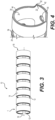
- FIG. 2A An example expandable sheath 10 is shown in FIG. 2A .
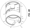
- FIG. 2B An enlarged view of an end of the sheath 10 is provided in FIG. 2B .
- the sheath 10 includes a longitudinally extending spine 12 having a plurality of curved arms 14 extending alternately from opposite sides of the spine 12. As depicted in FIG. 2A , the opposing curved arms 14 are offset such that the body/length of the curved arm 14a extends between adjacent curved arms 14b, 14c provided on the opposite side of the spine 12.
- the sheath 10 can be constructed in layers. For example, as illustrated in FIG. 2A , the sheath 10 can include three layers of material defining the spine 12 and curved arms 14. As illustrated in FIG.
- the expandable sheath 10 has a first (innermost) layer 20 that includes a first longitudinally extending spine 22 and a first plurality of curved arms 24 attached to the spine 22.
- An additional, second (middle) layer 30 extends over the outside surface of the first layer 20.
- the second layer 30 includes an additional, second longitudinally extending spine 32 and an additional, second plurality of curved arms 34.
- the curved arms 34 of the second layer 30 overlay the curved arms 24 of the first layer 20.
- the embodiment of FIGS. 2A-B also includes a third (outermost) layer 40 including a third longitudinally extending spine 42 and a third plurality of curved arms 44.
- the curved arms 44 of the third layer 40 overlay the curved arms 34 of the second layer 30.
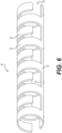
- the curved arms 14 and the spine 12 can be formed from only one layer, as shown in the embodiment of the expandable sheath illustrated in FIG. 6 .
- the longitudinally extending spine 12 provides the sheath 10 with stiffness in the longitudinal direction. This stiffness reduces bending or kinking in the longitudinal direction while the sheath 10 is being pushed into the patient's vasculature.
- Each curved arm 14 is attached to and extends away from the longitudinally extending spine 12 and curves around the longitudinal axis 16 ( FIG. 3 ) of the sheath 10.
- the spine 12 extends parallel to the longitudinal axis 16.
- the circumferential curvature of the curved arms 14 around the longitudinal axis 16 at least partially defines a longitudinally extending lumen 18 through which the prosthetic heart valve 122 will pass.
- the various layers of curved arms 24, 34, 44 are configured to slide along each other in the circumferential direction as the sheath 10/arms 14 move between an expanded and non-expanded condition. This sliding occurs along the (circumferential) length of the curved arms 14 when the sheath 10 expands and contracts as a prosthetic heart valve 122 or other prosthetic device is pushed through the longitudinally extending lumen 18 of the sheath 10.
- the curved arms 24, 34, 44 are elastically resilient, moving away from the longitudinal axis 16 when exposed to a radially outwardly directed force (such as the force from a prosthetic heart valve 122 moving through the lumen 18), and then moving back toward the longitudinal axis 16 upon release of the force (for example, once the prosthetic heart valve 122 has passed).
- a radially outwardly directed force such as the force from a prosthetic heart valve 122 moving through the lumen 18
- the curved arms 14 of the embodiment shown in FIGS. 2-5 extend from their respective longitudinally extending spine 12 in alternating directions.
- the first set of curved arms 14 circle the longitudinal axis 16 in a first (counterclockwise) direction.
- the next set curved arms 14 circle the longitudinal axis 16 in the opposite (clockwise) direction, the next set of curved arms 14 curve back in the first direction, and so on, along the entire length of the sheath 10.
- the direction of the curved arms 14 can alternate along the length of the sheath 10 at regular and/or irregular intervals.
- the curved arms 14 extending in alternating directions along the length of the sheath 10 is advantageous because during expansion, the profile of the sheath 10 stays somewhat circular, a shape well adapted to the shape of the vasculature. Additionally, the passing device is fully encircled by the curved arms 14 during its passage, protecting the vasculature from the passing device. It is also contemplated that all of the curved arms 14 can extend in the same direction along the length of the sheath 10.
- the circumferential distance that the curved arms 14 extend around the longitudinal axis 16 can vary by embodiment.
- the embodiment of FIG. 2A shows the curved arms 14 extending greater than 270-degrees around the longitudinal axis 16, but other embodiments can have curved arms extend to a greater or lesser extent around the longitudinal axis 16.
- the curved arms 14 could extend greater than 180-degrees, including 190, 200, 210, 220, 230, 240, 250, 260, 270, 280, 290, 300, 310, 320, 340, 350, or greater than 350 degrees up to 360-degrees.
- fixation mechanism can include an elastic polymer layer or tubing 50 at least partially encapsulating the layers of the sheath 10, or it could include one or more circumferential rings 52 extending around the outermost layer, as seen in FIGS. 1C and 20 and described in more detail below.
- the fixation mechanism can be applied to or between the layered longitudinal spines 12 to prevent longitudinal slippage of the layers with respect to each other.
- the fixation mechanism could include a mechanical or chemical fastener coupling the layers of the sheath 10 together.
- the fixation mechanism could include a suture, a rivet, or a bonding agent.
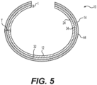
- the fixation mechanism includes a suture that can be threaded through a bore hole 54 extending through the layered longitudinally extending spines 12, as shown in FIG. 5 .
- the holes 54 through each of the layers 20, 30, 40 are aligned so that the suture can be threaded through each longitudinally extending spine 22, 32, 42.
- the sheath 10 could also include multiple mechanical and/or chemical fixation mechanisms provided along the length of the spine 12.
- the sheath 10 could include a suture extending along the spine 12, through a series of suture holes 54, a row of rivets, and/or longitudinally extending strips of bonding agent/adhesive provided between the layered spines 22, 32, 42.
- the thickness (t) of an individual layer can be, in some embodiments, from 0.04 to 0.1 millimeters. In embodiments including three layers, the total thickness (T) of the sheath wall is therefore from 0.12 to 0.3 millimeters. In certain embodiments, the thickness of an individual layer is 0.05 millimeters, such that a three layer embodiment has a total sheath wall thickness 29 of 0.15 millimeters.
- the layering of multiple thin curved arms 14 provides certain advantages to an expandable sheath 10. Because each individual layer is constructed from a thin layer of material rather than if the sheath 10 were constructed from a (thicker) single layer, the individual arms have improved flexibility over a single curved arm having the same overall thickness.
- the multiple layers of curved arms 14 create a structure similar to a leaf spring.
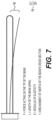
- the flexibility of a beam (or curved arm) increases as thinner layers are used according to the formula shown in FIG. 7 .
- increased flexibility is accompanied by a decrease in stiffness, such that the individual curved arm 14 is weaker in all directions.
- the layering of multiple thin curved arms 14 offsets this decrease in stiffness. Because every layer acts separately by sliding on the next one in the circumferential direction, the structure remains relatively stiff, especially in the longitudinal direction, while achieving a high range of deflection.
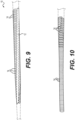
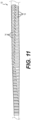
- FIGS. 8-12 illustrate an example sheath 10 having curved arms 14 arranged more closely together and/or in contact.
- the opposing curved arms 14 are arranged so there is sliding contact between opposing arms 14 as the sheath 10 expands and contracts. While individual layers are not shown in FIGS. 8-12 , it is contemplated that the sheath 10 of FIGS. 8-12 can be a single or multiple layer sheath 10.
- variable features include the extent of circumferential curvature of the curved arms 14, the width of the longitudinal spine 12, the length of the curved arms 14, the overall inner and outer diameters of the sheath 10, the width of the curved arms 14, and the extent to which individual layers overlap each other in the longitudinal direction. Widening (circumferentially) the longitudinal spine 12 creates a sheath that better withstands pushing and limits kinking. However, the widening of the spine 12 results in a corresponding shortening of the curved arms 14, which determines the maximum diameter the sheath 10 can be opened while keeping the passing implant at least partially contained by the curved arms 14.
- the outer diameter of the sheath 10 can vary from 3.3 to 3.8 millimeters in the nonexpanded state, and from 7.5 to 8 millimeters in the expanded state.
- the individual layers can overlap fully in the longitudinal direction, or they may be shifted from each other by 0.1 to 0.3 millimeters per layer.
- FIGS. 8-11 depict the example sheath 10 before and during expansion by a tapered dilator.
- FIGS. 9-11 illustrate a tapered dilator (dashed lines) for the purpose of demonstrating the expansion of the curved arms 14.
- the curved arms 14 can be seen extending away from the longitudinal spine 12.
- the narrow end of the tapered dilator is positioned at the distal end of the sheath 10 (left side of the figure) and the curved arms 16 are shown to extend further around the diameter of the sheath 10 such that their ends can be seen adjacent the longitudinal spine 12.
- FIGS. 10 and 11 show the opposite side of the expandable sheath 10 with only the curved arms 14 visible.
- FIG. 10 and 11 show the opposite side of the expandable sheath 10 with only the curved arms 14 visible.
- FIG. 11 shows the expandable sheath 10 fully positioned over the tapered dilator. Moving from left to right within FIGS. 10 and 11 , the curved arms 14 are expanded to progressively wider diameters, such that their ends move farther and farther from the adjacent longitudinal spine 12 (not shown) and closer to each other (as best seen on the far right side of FIG. 11 ).
- FIG. 12 shows an example prosthetic device 112 being delivered through an expandable sheath 10.
- the curved arms 14 at the distal end have not yet been expanded by the prosthetic device.
- the prosthetic device has already passed the curved arms 14 at the proximal end (far right of the figure), demonstrating that the curved arms 14 return to a non-expanded state after the passage of the prosthetic device.
- the sheath shown in FIG. 12 does not have an elastic polymer layer or tubing 50 over the layers (as described in more detail below).
- an elastic polymer layer or tubing 50 could be included to urge the curved arms 14 to return to their original position after passage of the prosthetic device.
- FIGS. 13-14 illustrate an example sheath 10 having curved arms 14 that extend from the longitudinal spine 12 at an angle.
- the sheath 10 depicted in FIGS. 13-14 has curved arms 14 extend from the longitudinal spine 12 at an angle other than 90-degrees.
- the curved arms 14 in the example sheath 10 are also generally longer than the curved arms 14 depicted in the embodiment of FIG. 2 . Because the curved arms 14 are longer, they can be opened to a larger expanded diameter and with less resistance. Also, because there are fewer arms in general, there are fewer edges to generate friction with a passing device.
- FIG. 13 shows the expandable sheath 10 having angled curved arms 14 in the non-expanded position.
- FIG. 14A shows the layered curved arms 24, 34, 44 in the expanded position, for example, as if expanded to allow passage of a prosthetic device.
- FIG. 14B shows a magnified view of FIG. 14A .
- the arms 14 extend from the spine 12 at an angle of about 45-degrees (measured relative to the longitudinal axis of the sheath 10 and/or longitudinally extending side of the spine 12 and the side edge the curved arm 14).
- the curved arms 14 it is possible for the curved arms 14 to extend from a single side of the spine 12 at a variety of angles, less than and including 90-degrees.
- the curved arms 14 of the depicted embodiment extend from 270 to 360-degrees around the longitudinal axis 16, but could be designed to curve around the longitudinal axis 16 to a lesser extent.
- the curved arms 14 can return to their original position due to the shape memory property of the starting material.
- the various layers 20, 30, 40 of the sheath 10 can be partially encapsulated in an elastic polymer tubing 50, as explained in more detail below with respect to FIG. 20 .
- the elastic polymer tubing 50 facilitates the return of the curved arms 14 to their original position by exerting an inward force on the curved arms 14 when they are in their expanded state.
- the curved arms 14 extend from the longitudinal spine 12 in directly opposing pairs.
- a first curved arm 14A extends from the spine 12 in a first (counterclockwise) direction, directly opposite the spine 12
- a corresponding second curved arm 14B extends from the spine 12 in a second (clockwise) direction.
- the series of opposing curved arms 14 can repeat along the length of the spine 12, creating the appearance of ribs.
- the curved arms 14 in this embodiment can only extend around the longitudinal axis from 90 to 180-degrees.
- the two sheath layers 20, 30 are depicted as extending opposite each other such that the spine 22, 32 of each sheath layer extends on opposite sides of the circumference of the sheath 10. Though depicted as separate the layers are coupled together via an elastic polymer tubing 50 (not shown) that extends over/around the opposing layers 20, 30. Similar to the sheath depicted in FIG. 13 , the curved arms 24, 34 extend from the longitudinally extending spines 22, 32 in opposing pairs. However, unlike the previous embodiments, the longitudinally extending spines 22, 32 are spaced from each other in the circumferential direction by 180-degrees. Other embodiments can also include various circumferential spacing of the longitudinally extending spines 22, 32.
- the longitudinally extending spines 22, 32 can be circumferentially spaced from each other by anywhere from 0 to 180-degrees.
- embodiments with circumferentially spaced longitudinally extending spines 12 can be encapsulated within, at least partially, an elastic polymer layer or tubing 50, such as is shown in FIG. 20 .
- one or more circumferentially extending rings 52 can be placed around the outermost layer 20, 30 and/or the elastic polymer layer or tubing 50.
- Some embodiments can include layers 20, 30, 40 that are longitudinally staggered from one another.
- a curved arm 24 of the first layer 20 can extend into the space between curved arms to a greater extent than the curved arm 34 of the second layer 30, which is positioned above/around it. This reduces the total amount of negative space between the combined or layered sets of curved arms 24, 34, 44.
- This feature can reduce kinking along the longitudinal axis 16, but can also decrease bendability by increasing the stiffness of the sheath 10.
- the amount of staggering of the layers can be adapted to suit varying applications.
- FIGS. 18A-19B show an example expandable sheath 10 including a number of links formed from curved arms 14 that pivot at one end from a common longitudinally-extending axis to allow the sheath 10 to expand and contract during delivery of the prosthetic device.
- the curved arms 14 can be coupled to a rod-like spine 12.
- the spine 12 can be formed by threading a metal wire, cable, thin rod, or other suitable material, through the links.
- individual curved arms 14 can be coupled to adjacent curved arms 14 via a projection/pivot arm extending from an end surface of each arm 14.
- the curved arms 14 can include a pin-like projection extending from an end surface of the curved arm 14 and a corresponding opening on an opposite end surface of the curved arm 14.
- the projection extending from the distal end surface of a first curved arm 14 is received within an opening provided in the proximal end surface of a next adjacent curved arm 14.
- the projection is rotatably received within the opening of an adjacent curved arm 14 to allow each of the curved arms 14 to pivot at the projection/opening, thus allowing the sheath 10 to expand/contract.
- the curved arms 14 are rotationally coupled at alternating ends to the spine 12.
- Each curved arm extends circumferentially at least 180-degrees around the longitudinal axis 16 of the sheath 10 in a non-expanded state ( FIG. 18A ).
- the curved arms can also be constructed from an elastically resilient material, such as a flexible polymer, such that during delivery of the prosthetic device, the curved arms 14 rotate and/or flex about the spine 12 to facilitate localized expansion of the sheath 10.
- FIG. 19A illustrates the sheath 10 in an expanded state.
- the curved arms 14 can alternate in a rotational and/or flexing direction along the sheath 10. For example, as provided in FIGS.
- the curved arms 14 rotate/flex from the spine 12 in alternating clockwise/counterclockwise directions along the length of the sheath 10.
- the first curved arm 14A at the proximal end of the sheath 10 extends from the spine 12 in a first (clockwise) direction.
- the next/adjacent curved arm 14B extends from the spine 12 in a second, opposite (counterclockwise) direction.
- the curved arms 14 are coupled to the spine 12 such that they all rotate/flex from the spine 12 in the same direction, e.g., all of the curved arms 14 may rotate/flex from the spine in a clockwise direction.
- the curved arms 14 are coupled to the spine 12 such that the direction the curved arms 14 rotate/flex from the spine 12 alternate at regular and/or irregular intervals.
- the curved arms 14 engage or otherwise interlock with an adjacent arm during expansion and contraction of the sheath 10, such that the arms slide against each other.
- the curved arms 14 can include a projection or ridge 11 sized and configured to engage a corresponding recess/groove 13 provided on an adjacent curved arm 14.
- An example ridge 11 structure is illustrated in FIGS. 19A and 19B .
- the ridge 11 extends from an end surface of the curved arm 14 and can define a curved shape generally corresponding to the shape of the curved arm 14 (in cross-section).
- FIGS. 19A and 19B illustrate the ridge 11 extending from the curved arm 14 along a majority of the length of the curved arm 14, but of course the ridge can extend along less than half of the circumferential length of the curved arm 14.
- FIGS. 19A and 19B illustrate the ridge 11 extending continuously from the end surface of the curved arm 14.
- the ridge 11 may also extend intermittently from the end of the curved arm 14. That is, the ridge 11 may include a number of ridges 11 that extend from the end of the curved arm 14 with breaks in between.
- the curved arms 14 include a corresponding groove 13 on the opposite side of the curved arm 14 from the ridge 11.
- the groove 13 is sized and configured to slidingly receive the ridge 11 such that adjacent arms 14 are engaged/interlocked during expansion and contraction of the sheath 10. Similar to the ridge 11, the groove defines a curved shape generally corresponding to the shape of the curved arm 14.
- the groove 13 includes an opening 15 in the curved arm 14 for receiving the ridge 11.
- the groove 13 may not include a receiving opening but rather define a bounded recess provided on the end surface curved arm 14 such that the ridge 11 of an adjacent curved arm 14 is not released from the groove 13, also ensuring that the curved arms 14 overlap or are always in contact when the sheath 10 is fully expanded.
- the groove 13 also includes an end surface 17 at the terminating point of the groove 13 within the curved arm 14. The end surface 17 can provide a contact/engagement surface for the ridge 11 to limit further contraction of the sheath 10. That is, engagement between the end surface 17 and an end of the ridge 11 will limit rotational movement of the corresponding arms 14 and contraction of the sheath 10.
- the size and shape of the ridge 11, and corresponding grove 13, may vary.
- the ridge 11 may define a square or curved end surface.
- the ridge 11 and/or groove 13 can include a tapered surface for facilitating sliding engagement and/or flexation of the curved arms 14.
- the ridge 11 can be constructed from the same or a different material from the curved arm 14.
- the ridge 11 can be constructed from a more flexible and/or elastic material than the curved arm 14.
- the ridge 11 can be constructed from a more rigid/stiff material than the curved arm 14.
- the curved arm 14 does not include a groove. Rather, the ridge 11 slides along an inner or outer surface of the adjacent curved arm 14.
- the ridge 11 slides within a correspondingly shaped recess provided on the inner or outer surface of the adjacent curved arm 14.
- the sheath 10 can also include an elastic polymer tubing 50 encasing at least part of the length of expandable sheath 10.
- An example elastic polymer tubing 50 is illustrated in FIGS. 1C and 20 .
- the elastic polymer tubing 50 can extend around the outside of the sheath 10, through the inside of the sheath 10 (between the first (innermost) layer 20 and the longitudinally extending lumen 18), or both.
- the elastic polymer tubing 50 provides an inwardly directed radial force that serves as a fixation mechanism to prevent longitudinal slippage between the various layers of the expandable sheath 10.
- the compressive force provided by the elastic polymer tubing 50 can also facilitate the movement of the curved arms 14 back toward the longitudinal axis 16 after their expansion by a passing prosthetic device.
- the elastic polymer tubing 50 creates a smooth surface that can minimize damage to the vascular system as the sheath 10 is being positioned and during insertion of the delivery system and implant through the sheath 10.
- the elastic polymer tubing 50 can be included through the inside of the sheath 10 to protect a passing prosthetic device from damage by the sheath 10 and to reduce friction between the sheath 10 and the device during its passage.
- the elastic polymer tubing 50 can be formed from a variety of materials including polyether ether ketone (PEEK), polyethylene terephthalate (PET), polyphenylene sulfide (PPS), and composite materials reinforced by carbon or glass fibers.
- PEEK polyether ether ketone
- PET polyethylene terephthalate
- PPS polyphenylene sulfide
- the elastic polymer tubing 50 will be formed of biocompatible, anti-clotting materials.
- the expandable sheath 10 can be constructed of a nitinol starting material.
- the nitinol material can be used for its super elastic properties, i.e. to bring the curved arms back to starting position after the passing of a prosthetic device.
- Other starting materials could include materials with high elasticity, polymer materials or stainless steel that has been treated to increase elasticity. Treatments to increase the elasticity of the stainless steel could include, for example, thermal treatments, chemical treatments, or mechanical treatments. The individual layers need not be formed from the same starting material.
- the sheath 10 and its individual elements can be laser cut from a tube of the starting material.
- the material could be cut from a sheet and then bent to form the sheath. The bending could be performed using rolling combined with heat treatment, or by cold rolling.
- a shape memory material can also be processed at this stage to set the arms to the nonexpanded state.
- the expandable sheath 10 can be used to deliver, remove, repair, and/or replace a prosthetic device.
- the sheath 10 described above can be used to deliver a prosthetic heart valve to a patient.
- a heart valve in a crimped or compressed state mounted on the distal end portion of an elongated delivery catheter is inserted into the sheath.
- the delivery catheter and heart valve can be advanced through the sheath and through the patient's vasculature to the treatment site, where the valve is implanted.
- the expandable sheath 10 can be useful for other types of minimally invasive surgery, such as any surgery requiring introduction of an apparatus into a subject's vessel.
- the expandable sheath 10 can be used to introduce other types of delivery apparatus for placing various types of intraluminal devices (e.g., stents, stented grafts, balloon catheters for angioplasty procedures, etc.) into many types of vascular and non-vascular body lumens (e.g., veins, arteries, esophagus, ducts of the biliary tree, intestine, urethra, fallopian tube, other endocrine or exocrine ducts, etc.).
- intraluminal devices e.g., stents, stented grafts, balloon catheters for angioplasty procedures, etc.
- vascular and non-vascular body lumens e.g., veins, arteries, esophagus, ducts of the biliary tree,
Landscapes
- Health & Medical Sciences (AREA)
- Life Sciences & Earth Sciences (AREA)
- Engineering & Computer Science (AREA)
- Animal Behavior & Ethology (AREA)
- Veterinary Medicine (AREA)
- Biomedical Technology (AREA)
- Heart & Thoracic Surgery (AREA)
- Public Health (AREA)
- General Health & Medical Sciences (AREA)
- Cardiology (AREA)
- Biophysics (AREA)
- Pulmonology (AREA)
- Anesthesiology (AREA)
- Hematology (AREA)
- Transplantation (AREA)
- Vascular Medicine (AREA)
- Oral & Maxillofacial Surgery (AREA)
- Prostheses (AREA)
Applications Claiming Priority (5)
| Application Number | Priority Date | Filing Date | Title |
|---|---|---|---|
| US201662360162P | 2016-07-08 | 2016-07-08 | |
| US201762475759P | 2017-03-23 | 2017-03-23 | |
| US15/636,201 US10856981B2 (en) | 2016-07-08 | 2017-06-28 | Expandable sheath and methods of using the same |
| PCT/US2017/040094 WO2018009416A1 (en) | 2016-07-08 | 2017-06-29 | Expandable sheath and methods of using the same |
| EP17824730.0A EP3481337B1 (de) | 2016-07-08 | 2017-06-29 | Erweiterbare hülse und verfahren zur verwendung davon |
Related Parent Applications (1)
| Application Number | Title | Priority Date | Filing Date |
|---|---|---|---|
| EP17824730.0A Division EP3481337B1 (de) | 2016-07-08 | 2017-06-29 | Erweiterbare hülse und verfahren zur verwendung davon |
Publications (2)
| Publication Number | Publication Date |
|---|---|
| EP4374907A2 true EP4374907A2 (de) | 2024-05-29 |
| EP4374907A3 EP4374907A3 (de) | 2024-07-17 |
Family
ID=60892894
Family Applications (2)
| Application Number | Title | Priority Date | Filing Date |
|---|---|---|---|
| EP23217848.3A Pending EP4374907A3 (de) | 2016-07-08 | 2017-06-29 | Expandierbare hülle und verfahren zur verwendung davon |
| EP17824730.0A Active EP3481337B1 (de) | 2016-07-08 | 2017-06-29 | Erweiterbare hülse und verfahren zur verwendung davon |
Family Applications After (1)
| Application Number | Title | Priority Date | Filing Date |
|---|---|---|---|
| EP17824730.0A Active EP3481337B1 (de) | 2016-07-08 | 2017-06-29 | Erweiterbare hülse und verfahren zur verwendung davon |
Country Status (3)
| Country | Link |
|---|---|
| US (3) | US10856981B2 (de) |
| EP (2) | EP4374907A3 (de) |
| WO (1) | WO2018009416A1 (de) |
Families Citing this family (60)
| Publication number | Priority date | Publication date | Assignee | Title |
|---|---|---|---|---|
| US10285720B2 (en) | 2014-03-11 | 2019-05-14 | Neuravi Limited | Clot retrieval system for removing occlusive clot from a blood vessel |
| ES2989493T3 (es) | 2014-06-13 | 2024-11-26 | Neuravi Ltd | Dispositivos para eliminar las obstrucciones agudas de los vasos sanguíneos |
| US10265086B2 (en) | 2014-06-30 | 2019-04-23 | Neuravi Limited | System for removing a clot from a blood vessel |
| US10856981B2 (en) * | 2016-07-08 | 2020-12-08 | Edwards Lifesciences Corporation | Expandable sheath and methods of using the same |
| US10980569B2 (en) * | 2016-12-09 | 2021-04-20 | Boston Scientific Scimed, Inc. | Introducer with expandable capabilities |
| US11957899B2 (en) * | 2018-02-15 | 2024-04-16 | Brown University | Coupled annulus and catheter system for placement of biocompatible brain electrodes and like devices |
| KR20250049430A (ko) | 2018-04-09 | 2025-04-11 | 에드워즈 라이프사이언시스 코포레이션 | 팽창 가능 외장 |
| US11648115B2 (en) * | 2018-10-03 | 2023-05-16 | Edwards Lifesciences Corporation | Expandable introducer sheath |
| EP4000540B1 (de) | 2019-03-04 | 2024-02-14 | Neuravi Limited | Betätigter gerinnungsentfernungskatheter |
| WO2020219363A2 (en) * | 2019-04-22 | 2020-10-29 | W. L. Gore & Associates, Inc. | Expandable sheath |
| ES2987037T3 (es) | 2019-09-11 | 2024-11-13 | Neuravi Ltd | Catéter bucal expansible |
| CA3142639A1 (en) | 2019-10-08 | 2021-04-15 | Edwards Lifesciences Corporation | Expandable sheath |
| DE102019007222A1 (de) * | 2019-10-17 | 2021-04-22 | Xenios Ag | Führungselement für ein steuerbares Gefäßaufweitungssystem |
| US12539130B2 (en) | 2019-11-27 | 2026-02-03 | Neuravi Limited | Aspiration catheter, systems, and methods thereof |
| US11779364B2 (en) | 2019-11-27 | 2023-10-10 | Neuravi Limited | Actuated expandable mouth thrombectomy catheter |
| US11839725B2 (en) | 2019-11-27 | 2023-12-12 | Neuravi Limited | Clot retrieval device with outer sheath and inner catheter |
| US11944327B2 (en) | 2020-03-05 | 2024-04-02 | Neuravi Limited | Expandable mouth aspirating clot retrieval catheter |
| US11633198B2 (en) | 2020-03-05 | 2023-04-25 | Neuravi Limited | Catheter proximal joint |
| US11883043B2 (en) | 2020-03-31 | 2024-01-30 | DePuy Synthes Products, Inc. | Catheter funnel extension |
| US11759217B2 (en) | 2020-04-07 | 2023-09-19 | Neuravi Limited | Catheter tubular support |
| EP4149603B1 (de) | 2020-05-13 | 2026-03-04 | Edwards Lifesciences Corporation | Knickbeständige dehnbare hülle |
| WO2022016059A1 (en) | 2020-07-17 | 2022-01-20 | Edwards Lifesciences Corporation | Expandable introducer for dilating the distal tip of an introducer sheath |
| JP2023541174A (ja) | 2020-09-14 | 2023-09-28 | エドワーズ ライフサイエンシーズ コーポレイション | リバースバヨネット係止ハブを含む拡張可能シース |
| WO2022081285A1 (en) | 2020-10-13 | 2022-04-21 | Edwards Lifesciences Corporation | Expandable sheath including smart introducer |
| CA3196417A1 (en) | 2020-10-14 | 2022-04-21 | Edwards Lifesciences Corporation | Expandable sheath with radiopaque features |
| EP4240287A1 (de) * | 2020-11-04 | 2023-09-13 | Edwards Lifesciences Corporation | Expandierbare hülle für transaxillären zugang |
| WO2022099000A1 (en) | 2020-11-05 | 2022-05-12 | Edwards Lifesciences Corporation | Self-expanding, two component sheath and methods of using the same |
| US11872354B2 (en) * | 2021-02-24 | 2024-01-16 | Neuravi Limited | Flexible catheter shaft frame with seam |
| WO2023014551A1 (en) | 2021-08-06 | 2023-02-09 | Edwards Lifesciences Corporation | Expandable sheath |
| JP2024530791A (ja) * | 2021-09-02 | 2024-08-23 | エドワーズ ライフサイエンシーズ コーポレイション | インプラント送達用の拡張可能なシース |
| US11937839B2 (en) | 2021-09-28 | 2024-03-26 | Neuravi Limited | Catheter with electrically actuated expandable mouth |
| US12011186B2 (en) | 2021-10-28 | 2024-06-18 | Neuravi Limited | Bevel tip expandable mouth catheter with reinforcing ring |
| CN115040756B (zh) | 2022-08-16 | 2022-11-04 | 生一科技(北京)有限公司 | 导管支撑装置和管腔介入系统 |
| EP4580722A1 (de) | 2022-08-30 | 2025-07-09 | Edwards Lifesciences Corporation | Einführvorrichtung mit expandierbarem stopfen |
| WO2024107693A1 (en) | 2022-11-17 | 2024-05-23 | Edwards Lifesciences Corporation | Expandable sheath including strain relief layer |
| EP4648722A1 (de) | 2023-01-11 | 2025-11-19 | Edwards Lifesciences Corporation | Hülle und ladevorrichtung zur einführung einer prothetischen vorrichtung |
| WO2024178193A1 (en) | 2023-02-23 | 2024-08-29 | Edwards Lifesciences Corporation | Expandable introducer |
| EP4688076A1 (de) | 2023-03-24 | 2026-02-11 | Edwards Lifesciences Corporation | Aufblasbare einführschleuse |
| WO2024216196A1 (en) | 2023-04-14 | 2024-10-17 | Edwards Lifesciences Corporation | Folding mechanism for an introducer sheath |
| WO2024226928A1 (en) | 2023-04-27 | 2024-10-31 | Edwards Lifesciences Corporation | Expandable sheath and pre-dilation tool |
| WO2024238737A1 (en) | 2023-05-17 | 2024-11-21 | Edwards Lifesciences Corporation | Lead screw driven sheath dilator |
| WO2024263844A1 (en) | 2023-06-22 | 2024-12-26 | Edwards Lifesciences Corporation | Pre-dilated expandable sheath with protective cover |
| WO2025019168A1 (en) | 2023-07-14 | 2025-01-23 | Edwards Lifesciences Corporation | Two component introducer assembly |
| WO2025029777A1 (en) | 2023-08-01 | 2025-02-06 | Edwards Lifesciences Corporation | Introducer/dilator with folded balloon |
| WO2025034435A1 (en) | 2023-08-04 | 2025-02-13 | Edwards Lifesciences Corporation | Hybrid expandable sheath |
| WO2025128301A1 (en) | 2023-12-13 | 2025-06-19 | Edwards Lifesciences Corporation | Expandable introducer sheath |
| WO2025227014A1 (en) | 2024-04-26 | 2025-10-30 | Edwards Lifesciences Corporation | In-vessel sheath dilator |
| WO2025235475A1 (en) | 2024-05-07 | 2025-11-13 | Edwards Lifesciences Corporation | Expandable sheath and introducer |
| WO2025240167A1 (en) | 2024-05-15 | 2025-11-20 | Edwards Lifesciences Corporation | Expandable sheath and introducer |
| WO2025255006A1 (en) | 2024-06-03 | 2025-12-11 | Edwards Lifesciences Corporation | Delivery sheath stabilization devices and systems |
| WO2025264699A1 (en) | 2024-06-20 | 2025-12-26 | Edwards Lifesciences Corporation | Catheter introducer releasably coupled to a normally expanded stretchable sheath |
| WO2025264701A1 (en) | 2024-06-21 | 2025-12-26 | Edwards Lifesciences Corporation | Mechanically expanding sheath tip |
| WO2026006081A1 (en) | 2024-06-24 | 2026-01-02 | Edwards Lifesciences Corporation | Hybrid proximal cap design for access sheath and manufacturing method |
| WO2026015256A1 (en) | 2024-07-11 | 2026-01-15 | Edwards Lifesciences Corporation | Expandable sheath with distal tip restraining member |
| WO2026024430A1 (en) | 2024-07-22 | 2026-01-29 | Edwards Lifesciences Corporation | Spacer for expandable introducer sheath |
| WO2026030054A1 (en) | 2024-07-30 | 2026-02-05 | Edwards Lifesciences Corporation | Pre-shaped and atraumatic tips of expandable sheaths |
| WO2026039724A2 (en) | 2024-08-16 | 2026-02-19 | Edwards Lifesciences Corporation | Devices and methods for stabilizing sheath systems |
| WO2026054987A1 (en) | 2024-09-04 | 2026-03-12 | Edwards Lifesciences Corporation | Multi-part in-sheath dilator |
| WO2026055349A1 (en) | 2024-09-05 | 2026-03-12 | Edwards Lifesciences Corporation | Introducer sheath and loader |
| WO2026072320A1 (en) | 2024-09-26 | 2026-04-02 | Edwards Lifesciences Corporation | Sheath system stabilizer for controlling expansion |
Family Cites Families (69)
| Publication number | Priority date | Publication date | Assignee | Title |
|---|---|---|---|---|
| US4035849A (en) | 1975-11-17 | 1977-07-19 | William W. Angell | Heart valve stent and process for preparing a stented heart valve prosthesis |
| US4592340A (en) | 1984-05-02 | 1986-06-03 | Boyles Paul W | Artificial catheter means |
| US4994077A (en) | 1989-04-21 | 1991-02-19 | Dobben Richard L | Artificial heart valve for implantation in a blood vessel |
| US5059177A (en) | 1990-04-19 | 1991-10-22 | Cordis Corporation | Triple lumen balloon catheter |
| DK124690D0 (da) | 1990-05-18 | 1990-05-18 | Henning Rud Andersen | Klapprotes til implantering i kroppen for erstatning af naturlig klap samt kateter til brug ved implantering af en saadan klapprotese |
| US5411552A (en) | 1990-05-18 | 1995-05-02 | Andersen; Henning R. | Valve prothesis for implantation in the body and a catheter for implanting such valve prothesis |
| US5728068A (en) | 1994-06-14 | 1998-03-17 | Cordis Corporation | Multi-purpose balloon catheter |
| US5554185A (en) | 1994-07-18 | 1996-09-10 | Block; Peter C. | Inflatable prosthetic cardiovascular valve for percutaneous transluminal implantation of same |
| US5599305A (en) | 1994-10-24 | 1997-02-04 | Cardiovascular Concepts, Inc. | Large-diameter introducer sheath having hemostasis valve and removable steering mechanism |
| US5639274A (en) | 1995-06-02 | 1997-06-17 | Fischell; Robert E. | Integrated catheter system for balloon angioplasty and stent delivery |
| DE19532846A1 (de) | 1995-09-06 | 1997-03-13 | Georg Dr Berg | Ventileinrichtung |
| US5591195A (en) | 1995-10-30 | 1997-01-07 | Taheri; Syde | Apparatus and method for engrafting a blood vessel |
| US6217585B1 (en) | 1996-08-16 | 2001-04-17 | Converge Medical, Inc. | Mechanical stent and graft delivery system |
| JP3968444B2 (ja) | 1996-08-23 | 2007-08-29 | ボストン サイエンティフィック サイムド,インコーポレイテッド | ステント固定装置を具備するステント搬送機構 |
| US5968068A (en) | 1996-09-12 | 1999-10-19 | Baxter International Inc. | Endovascular delivery system |
| EP0850607A1 (de) | 1996-12-31 | 1998-07-01 | Cordis Corporation | Klappenprothese zur Implantation in Körperkanälen |
| US6527979B2 (en) | 1999-08-27 | 2003-03-04 | Corazon Technologies, Inc. | Catheter systems and methods for their use in the treatment of calcified vascular occlusions |
| DE19907646A1 (de) | 1999-02-23 | 2000-08-24 | Georg Berg | Ventileinrichtung zum Einsetzen in ein Hohlorgan |
| US6858034B1 (en) | 1999-05-20 | 2005-02-22 | Scimed Life Systems, Inc. | Stent delivery system for prevention of kinking, and method of loading and using same |
| FR2815844B1 (fr) | 2000-10-31 | 2003-01-17 | Jacques Seguin | Support tubulaire de mise en place, par voie percutanee, d'une valve cardiaque de remplacement |
| US7018406B2 (en) | 1999-11-17 | 2006-03-28 | Corevalve Sa | Prosthetic valve for transluminal delivery |
| FR2800984B1 (fr) | 1999-11-17 | 2001-12-14 | Jacques Seguin | Dispositif de remplacement d'une valve cardiaque par voie percutanee |
| US6458153B1 (en) | 1999-12-31 | 2002-10-01 | Abps Venture One, Ltd. | Endoluminal cardiac and venous valve prostheses and methods of manufacture and delivery thereof |
| PL201632B1 (pl) | 2000-01-31 | 2009-04-30 | Cook Biotech | Zespół zastawki stentu |
| US6454799B1 (en) | 2000-04-06 | 2002-09-24 | Edwards Lifesciences Corporation | Minimally-invasive heart valves and methods of use |
| US7510572B2 (en) | 2000-09-12 | 2009-03-31 | Shlomo Gabbay | Implantation system for delivery of a heart valve prosthesis |
| WO2002022054A1 (en) | 2000-09-12 | 2002-03-21 | Gabbay S | Valvular prosthesis and method of using same |
| US6461382B1 (en) | 2000-09-22 | 2002-10-08 | Edwards Lifesciences Corporation | Flexible heart valve having moveable commissures |
| DE60115280T2 (de) | 2000-12-15 | 2006-08-10 | Angiomed Gmbh & Co. Medizintechnik Kg | Stent mit herzklappe |
| US7374571B2 (en) | 2001-03-23 | 2008-05-20 | Edwards Lifesciences Corporation | Rolled minimally-invasive heart valves and methods of manufacture |
| US7556646B2 (en) | 2001-09-13 | 2009-07-07 | Edwards Lifesciences Corporation | Methods and apparatuses for deploying minimally-invasive heart valves |
| US6733525B2 (en) * | 2001-03-23 | 2004-05-11 | Edwards Lifesciences Corporation | Rolled minimally-invasive heart valves and methods of use |
| US6893460B2 (en) | 2001-10-11 | 2005-05-17 | Percutaneous Valve Technologies Inc. | Implantable prosthetic valve |
| US7137184B2 (en) | 2002-09-20 | 2006-11-21 | Edwards Lifesciences Corporation | Continuous heart valve support frame and method of manufacture |
| US7399315B2 (en) | 2003-03-18 | 2008-07-15 | Edwards Lifescience Corporation | Minimally-invasive heart valve with cusp positioners |
| EP1615595B1 (de) | 2003-04-24 | 2009-10-21 | Cook Incorporated | Künstliche klappe für blutgefäss mit verbessertem fliessverhalten |
| US7553324B2 (en) | 2003-10-14 | 2009-06-30 | Xtent, Inc. | Fixed stent delivery devices and methods |
| US8128692B2 (en) | 2004-02-27 | 2012-03-06 | Aortx, Inc. | Prosthetic heart valves, scaffolding structures, and systems and methods for implantation of same |
| EP1753374A4 (de) | 2004-04-23 | 2010-02-10 | 3F Therapeutics Inc | Implantierbares protheseventil |
| JP2008513060A (ja) | 2004-09-14 | 2008-05-01 | エドワーズ ライフサイエンシーズ アーゲー | 心臓弁逆流の処置のためのデバイスおよび方法 |
| SE531468C2 (sv) | 2005-04-21 | 2009-04-14 | Edwards Lifesciences Ag | En anordning för styrning av blodflöde |
| JP4912395B2 (ja) | 2005-05-24 | 2012-04-11 | エドワーズ ライフサイエンシーズ コーポレイション | 迅速配置式補綴用心臓弁 |
| US7780723B2 (en) | 2005-06-13 | 2010-08-24 | Edwards Lifesciences Corporation | Heart valve delivery system |
| US8167932B2 (en) | 2005-10-18 | 2012-05-01 | Edwards Lifesciences Corporation | Heart valve delivery system with valve catheter |
| US8449606B2 (en) | 2005-10-26 | 2013-05-28 | Cardiosolutions, Inc. | Balloon mitral spacer |
| US7785366B2 (en) | 2005-10-26 | 2010-08-31 | Maurer Christopher W | Mitral spacer |
| US8778017B2 (en) | 2005-10-26 | 2014-07-15 | Cardiosolutions, Inc. | Safety for mitral valve implant |
| EP1959864B1 (de) | 2005-12-07 | 2018-03-07 | Medtronic, Inc. | Verbindungssysteme für zweistückige prothetische herzklappenanordnungen |
| US8147541B2 (en) | 2006-02-27 | 2012-04-03 | Aortx, Inc. | Methods and devices for delivery of prosthetic heart valves and other prosthetics |
| US9155641B2 (en) * | 2006-03-09 | 2015-10-13 | Cook Medical Technologies Llc | Expandable stent grafts |
| US8029556B2 (en) | 2006-10-04 | 2011-10-04 | Edwards Lifesciences Corporation | Method and apparatus for reshaping a ventricle |
| EP2148608A4 (de) * | 2007-04-27 | 2010-04-28 | Voyage Medical Inc | Steuerbarer gewebe-visualisierungs- und manipulationskatheter mit komplexer gestalt |
| US20080294230A1 (en) | 2007-05-24 | 2008-11-27 | Cook Incorporated | Apparatus and methods for deploying self-expanding stents |
| EP2211773A4 (de) * | 2007-11-30 | 2015-07-29 | Reva Medical Inc | Axial-radial verschachtelte expandierbare vorrichtung |
| PL2628464T5 (pl) | 2007-12-14 | 2024-10-28 | Edwards Lifesciences Corporation | Zastawka protetyczna |
| US20090276040A1 (en) | 2008-05-01 | 2009-11-05 | Edwards Lifesciences Corporation | Device and method for replacing mitral valve |
| US9061119B2 (en) | 2008-05-09 | 2015-06-23 | Edwards Lifesciences Corporation | Low profile delivery system for transcatheter heart valve |
| US8323335B2 (en) | 2008-06-20 | 2012-12-04 | Edwards Lifesciences Corporation | Retaining mechanisms for prosthetic valves and methods for using |
| US8652202B2 (en) | 2008-08-22 | 2014-02-18 | Edwards Lifesciences Corporation | Prosthetic heart valve and delivery apparatus |
| WO2010028300A1 (en) * | 2008-09-04 | 2010-03-11 | Curaseal Inc. | Inflatable device for enteric fistula treatment |
| US20100082000A1 (en) * | 2008-09-30 | 2010-04-01 | Medtronic, Inc. | Catheter system with reinforced member |
| CN103948460B (zh) * | 2008-10-10 | 2016-05-25 | 雷瓦医药公司 | 可扩展的滑动和锁定支架 |
| EP4119098A1 (de) | 2009-04-15 | 2023-01-18 | Edwards Lifesciences CardiAQ LLC | Gefässimplantat und freisetzungssystem |
| US8475522B2 (en) | 2009-07-14 | 2013-07-02 | Edwards Lifesciences Corporation | Transapical delivery system for heart valves |
| CA3020195C (en) | 2010-10-05 | 2020-10-27 | Edwards Lifesciences Corporation | Prosthetic heart valve |
| US10118020B2 (en) | 2011-12-07 | 2018-11-06 | Traumatek Solutions B.V. | Devices and methods for endovascular access and therapy |
| US9801657B2 (en) * | 2014-09-12 | 2017-10-31 | Freudenberg Medical, Llc | Expandable introducer sheath |
| US10327896B2 (en) * | 2015-04-10 | 2019-06-25 | Edwards Lifesciences Corporation | Expandable sheath with elastomeric cross sectional portions |
| US10856981B2 (en) * | 2016-07-08 | 2020-12-08 | Edwards Lifesciences Corporation | Expandable sheath and methods of using the same |
-
2017
- 2017-06-28 US US15/636,201 patent/US10856981B2/en active Active
- 2017-06-29 EP EP23217848.3A patent/EP4374907A3/de active Pending
- 2017-06-29 WO PCT/US2017/040094 patent/WO2018009416A1/en not_active Ceased
- 2017-06-29 EP EP17824730.0A patent/EP3481337B1/de active Active
-
2020
- 2020-12-07 US US17/113,268 patent/US11883288B2/en active Active
-
2023
- 2023-12-19 US US18/389,636 patent/US20240115382A1/en active Pending
Also Published As
| Publication number | Publication date |
|---|---|
| US11883288B2 (en) | 2024-01-30 |
| EP3481337B1 (de) | 2023-12-20 |
| US10856981B2 (en) | 2020-12-08 |
| EP4374907A3 (de) | 2024-07-17 |
| EP3481337A4 (de) | 2019-08-07 |
| WO2018009416A1 (en) | 2018-01-11 |
| US20210085459A1 (en) | 2021-03-25 |
| US20240115382A1 (en) | 2024-04-11 |
| EP3481337A1 (de) | 2019-05-15 |
| US20180008407A1 (en) | 2018-01-11 |
Similar Documents
| Publication | Publication Date | Title |
|---|---|---|
| US20240115382A1 (en) | Expandable sheath and methods of using the same | |
| US20240408349A1 (en) | Expandable sheath | |
| US12070388B2 (en) | Active introducer sheath system | |
| US20180256858A1 (en) | Expandable sheath with longitudinally extending reinforcing members | |
| EP3344189A1 (de) | Einführschleuse mit expandierbaren teilen | |
| US20230414900A1 (en) | Methods of making an expandable sheath | |
| WO2022099000A1 (en) | Self-expanding, two component sheath and methods of using the same | |
| JP2023541174A (ja) | リバースバヨネット係止ハブを含む拡張可能シース | |
| EP4228730A1 (de) | Expandierbare hülle mit intelligenter einführvorrichtung | |
| CN112804970B (zh) | 可扩展的引入器鞘管 |
Legal Events
| Date | Code | Title | Description |
|---|---|---|---|
| PUAI | Public reference made under article 153(3) epc to a published international application that has entered the european phase |
Free format text: ORIGINAL CODE: 0009012 |
|
| STAA | Information on the status of an ep patent application or granted ep patent |
Free format text: STATUS: THE APPLICATION HAS BEEN PUBLISHED |
|
| AC | Divisional application: reference to earlier application |
Ref document number: 3481337 Country of ref document: EP Kind code of ref document: P |
|
| AK | Designated contracting states |
Kind code of ref document: A2 Designated state(s): AL AT BE BG CH CY CZ DE DK EE ES FI FR GB GR HR HU IE IS IT LI LT LU LV MC MK MT NL NO PL PT RO RS SE SI SK SM TR |
|
| REG | Reference to a national code |
Ref country code: DE Ref legal event code: R079 Free format text: PREVIOUS MAIN CLASS: A61M0029000000 Ipc: A61F0002240000 |
|
| PUAL | Search report despatched |
Free format text: ORIGINAL CODE: 0009013 |
|
| P01 | Opt-out of the competence of the unified patent court (upc) registered |
Free format text: CASE NUMBER: APP_32588/2024 Effective date: 20240531 |
|
| AK | Designated contracting states |
Kind code of ref document: A3 Designated state(s): AL AT BE BG CH CY CZ DE DK EE ES FI FR GB GR HR HU IE IS IT LI LT LU LV MC MK MT NL NO PL PT RO RS SE SI SK SM TR |
|
| RIC1 | Information provided on ipc code assigned before grant |
Ipc: A61M 29/00 20060101ALI20240607BHEP Ipc: A61B 17/34 20060101ALI20240607BHEP Ipc: A61F 2/92 20130101ALI20240607BHEP Ipc: A61F 2/24 20060101AFI20240607BHEP |
|
| STAA | Information on the status of an ep patent application or granted ep patent |
Free format text: STATUS: REQUEST FOR EXAMINATION WAS MADE |
|
| 17P | Request for examination filed |
Effective date: 20250117 |