EP4374180B1 - Fluxgate-wandler zur strommessung - Google Patents
Fluxgate-wandler zur strommessung Download PDFInfo
- Publication number
- EP4374180B1 EP4374180B1 EP22743493.3A EP22743493A EP4374180B1 EP 4374180 B1 EP4374180 B1 EP 4374180B1 EP 22743493 A EP22743493 A EP 22743493A EP 4374180 B1 EP4374180 B1 EP 4374180B1
- Authority
- EP
- European Patent Office
- Prior art keywords
- fluxgate
- winding
- measurement
- current
- excitation coil
- Prior art date
- Legal status (The legal status is an assumption and is not a legal conclusion. Google has not performed a legal analysis and makes no representation as to the accuracy of the status listed.)
- Active
Links
Images



Classifications
-
- G—PHYSICS
- G01—MEASURING; TESTING
- G01R—MEASURING ELECTRIC VARIABLES; MEASURING MAGNETIC VARIABLES
- G01R15/00—Details of measuring arrangements of the types provided for in groups G01R17/00 - G01R29/00, G01R33/00 - G01R33/26 or G01R35/00
- G01R15/14—Adaptations providing voltage or current isolation, e.g. for high-voltage or high-current networks
- G01R15/18—Adaptations providing voltage or current isolation, e.g. for high-voltage or high-current networks using inductive devices, e.g. transformers
- G01R15/183—Adaptations providing voltage or current isolation, e.g. for high-voltage or high-current networks using inductive devices, e.g. transformers using transformers with a magnetic core
- G01R15/185—Adaptations providing voltage or current isolation, e.g. for high-voltage or high-current networks using inductive devices, e.g. transformers using transformers with a magnetic core with compensation or feedback windings or interacting coils, e.g. 0-flux sensors
-
- G—PHYSICS
- G01—MEASURING; TESTING
- G01R—MEASURING ELECTRIC VARIABLES; MEASURING MAGNETIC VARIABLES
- G01R15/00—Details of measuring arrangements of the types provided for in groups G01R17/00 - G01R29/00, G01R33/00 - G01R33/26 or G01R35/00
- G01R15/14—Adaptations providing voltage or current isolation, e.g. for high-voltage or high-current networks
- G01R15/18—Adaptations providing voltage or current isolation, e.g. for high-voltage or high-current networks using inductive devices, e.g. transformers
- G01R15/183—Adaptations providing voltage or current isolation, e.g. for high-voltage or high-current networks using inductive devices, e.g. transformers using transformers with a magnetic core
-
- G—PHYSICS
- G01—MEASURING; TESTING
- G01R—MEASURING ELECTRIC VARIABLES; MEASURING MAGNETIC VARIABLES
- G01R19/00—Arrangements for measuring currents or voltages or for indicating presence or sign thereof
- G01R19/0038—Circuits for comparing several input signals and for indicating the result of this comparison, e.g. equal, different, greater, smaller (comparing pulses or pulse trains according to amplitude)
-
- G—PHYSICS
- G01—MEASURING; TESTING
- G01R—MEASURING ELECTRIC VARIABLES; MEASURING MAGNETIC VARIABLES
- G01R19/00—Arrangements for measuring currents or voltages or for indicating presence or sign thereof
- G01R19/0092—Measuring current only
-
- G—PHYSICS
- G01—MEASURING; TESTING
- G01R—MEASURING ELECTRIC VARIABLES; MEASURING MAGNETIC VARIABLES
- G01R19/00—Arrangements for measuring currents or voltages or for indicating presence or sign thereof
- G01R19/18—Arrangements for measuring currents or voltages or for indicating presence or sign thereof using conversion of DC into AC, e.g. with choppers
- G01R19/20—Arrangements for measuring currents or voltages or for indicating presence or sign thereof using conversion of DC into AC, e.g. with choppers using transductors, i.e. a magnetic core transducer the saturation of which is cyclically reversed by an AC source on the secondary side
Definitions
- the present invention relates to a fluxgate transducer for use in current measurement applications.
- Fluxgate transducers are well known for use in current measurement applications, whereby the fluxgate transducer measures the intensity of the magnetic field generated by one or more primary conductors carrying the current to be measured.
- Fluxgate transducers comprise a saturable soft magnetic core surrounded by an excitation coil connected to a control circuit configured to alternatingly saturate the soft magnetic core.
- the fluxgate transducer is a small magnetic field sensing component placed in an airgap of a magnetic circuit core that surrounds a central passage through which one or more primary conductors extend.
- the fluxgate saturable magnetic core itself forms a central passage through which the primary conductor passes.
- the compensation coil may be wound around magnetic circuit with airgap, whereas in configurations where the fluxgate saturable magnetic core itself forms a central passage through which the primary conductor passes, the excitation coil may be used to provide the compensation current. In the latter case, the excitation current signal is superimposed on the compensation current signal.
- a fluxgate transducer provides for accurate measurement of primary currents or differential currents flowing in one or more primary conductors.
- Fluxgate transducers have a high sensitivity and low offset compared to the widely known transducers using Hall effect detectors.
- fluxgate transducers provide good isolation between the primary and secondary sides and are able to measure low frequency AC currents (up to several kHz) and DC currents.
- Fluxgate sensor technology is also known to be used for DC and AC leakage current measurement.
- current measurement systems are associated to safety functions, which is especially the case for sensors intended to measure leakage currents or residual currents.
- Illustrative examples of such applications include for instance sensors that are used to detect AC and/or DC leakage currents in solar panel applications or in automotive applications, for instance for on board charging systems.
- one of the applicable safety standards is the ISO26262 standard, and depending on the Hazard Analysis and Risk Assessment performed, the safety level of the function is ranked from quality management to ASIL D level safety.
- DC leakage current may be a safety function ranked ASIL D which is the highest required safety level. This level of safety requires a high reliability and leads to a high cost.
- current transducers should have a very low offset error. This is the case for battery monitoring devices where an offset in the current measured would lead to an over or underestimated state of charge of the battery.
- the sensor will monitor currents that will be most of the time zero, or close to zero, and should detect any change in the current value over a certain limit (threshold value). It is thus necessary for such applications to use a current sensor that have very low offset error.
- EP 1230734 A1 discloses a circuit for adaptively reducing dead time in switching circuits.
- a fluxgate current transducer including a control circuit and a fluxgate device comprising a saturable soft magnetic core surrounded by an excitation coil.
- the control circuit comprises an excitation coil drive circuit connected to the excitation coil configured to generate an alternating magnetic field to alternatingly saturate the soft magnetic core.
- the excitation coil comprises a first winding and a second winding connected together at a common point forming an input of the first winding and an output of the second winding.
- the first winding is connected in series to a first switch and the second winding is connected in series to a second switch, the first and second switches controlled by the control circuit to provide an excitation coil current in the first winding generating a magnetic field in the magnetic core in a first direction, and an excitation coil current in the second winding generating a magnetic field in the magnetic core in a second direction opposite to the first direction.
- the control circuit comprising a comparator having a first input connected to the excitation coil, wherein the control circuit comprises a PWM module connected to an output of the comparator and configured to control a timing of operation of the first and second switches, including introducing a dead time between switching from one excitation coil winding to the other excitation coil winding.
- the transducer comprises an analog measurement channel (M2) connected to the excitation coil after the first and second switches, comprising an ADC module, and wherein the analog measurement channel further comprises a DAC connected to the ADC module and further connected to an input of a comparator having a first input connected to the excitation coil.
- M2 analog measurement channel
- the analog measurement channel further comprises a DAC connected to the ADC module and further connected to an input of a comparator having a first input connected to the excitation coil.
- control circuit further comprises a First resistor connected on a high side of the fluxgate device, the control circuit further comprising a third switch S3 placed in a bypass circuit parallel with the First resistor configured to short circuit the First resistor when the switch is switched to the closed position, and wherein the analog measurement channel comprises a reference voltage source to control a supply reference voltage for the ADC module.
- the fluxgate transducer is connected to a user system to form together a current measurement system having at least three measurement channels, a first PWM channel M1, a second analog channel M2 and a third channel M3 provided by the test winding, the user system configured to compute a comparison of the measurement signals from the three measurement channels in order to determine correct or faulty operation.
- a second input of the comparator is connected to a DAC supplying an adjustable reference voltage for adjusting the output level of the comparator.
- the fluxgate transducer comprises a capture module connected to an output of the PWM module for capturing the timing of the switching signals.
- the transducer comprises an analog measurement channel (M2) connected to the excitation coil after the first and second switches, comprising an ADC module.
- M2 analog measurement channel
- the analog measurement channel further comprises a DAC connected to the ADC module and further connected to an input of a comparator having a first input connected to the excitation coil.
- the analog measurement channel further comprises an amplifier to increase the gain and scale an offset of the measurement of the signal fed into the ADC module.
- control circuit further comprises a first resistor connected on a high side or a low side of the fluxgate device, the control circuit further comprising a third switch S3 placed in a bypass circuit parallel with the first resistor configured to bypass the first resistor when the switch is switched to the closed position.
- the analog measurement channel comprises a reference voltage source to control a supply reference voltage for the ADC module.
- the transducer further comprises a test winding wound around the magnetic core, the test winding connected to a connection interface of the fluxgate transducer for connection to an electronic circuit of a user system.
- the test winding is configured to receive a test current from the user system and to output a voltage to the user system in a second mode of operation corresponding to a measurement signal of the magnetic field in the fluxgate device such that the test winding provides a third measurement channel M3.
- the fluxgate transducer is connected to a user system to form together a current measurement system having at least three measurement channels, a first PWM channel M1, a second analog channel M2 and a third channel M3 provided by the test winding, the user system configured to compute a comparison of the measurement signals from the three measurement channels in order to determine correct or faulty operation.
- the electronic circuit of the user system is configured to use two of the three measurement signals that have values closest to each other, and to discard the other measurement signal in case of a fault that affects one of the measurement channels.
- Also disclosed herein is a method of operating the fluxgate transducer in order to perform a demagnetization procedure comprising:
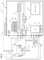
- a fluxgate current transducer for measuring a primary current flowing in one or more primary conductors 1 comprises a fluxgate device 2 and a control circuit 4 connected to the fluxgate device.
- the fluxgate device 2 comprises a saturable magnetic core and an excitation coil 8 wound around the saturable magnetic core 6.
- the excitation coil 8 comprises two windings, a first winding 8a and a second winding 8b, connected together at a common point 9 forming the input of the first winding and the output of the second winding.
- the excitation coil 8 is connected to an excitation coil drive circuit including a power supply controlled by the control circuit 4 configured to feed an excitation current through the excitation coil to alternatingly saturate the saturable magnetic core 6.
- the first and second windings 8a, 8b are supplied with a current in a sequential alternating manner, whereby the current in the first winding 8a generates a magnetic field in the magnetic core in a first direction, and the current in the second winding 8b generates a magnetic field in the magnetic core in a second direction opposite to the first direction, the changing magnetic fields in the magnetic core being switched sequentially, optionally with a short dead time period between the changeover from one winding to the other winding.
- the magnetic core is preferably made of a high permeability nano-crystalline magnetic material, for instance an FeSi or FeCo based nano-crystalline material due to the low temperature drift, high permeability, low coercive field, and adaptable permeability value of such materials.
- the magnetic material may have the following properties of BH loop shapes: rectangular (longitudinal field annealed), round (no field annealed, flat (transversal field annealed).
- the control circuit is configured to reach alternating saturation of the magnetic material as a function of the material's BH properties.
- the switching of the excitation current to supply either the first winding or the second winding is controlled by the control circuit 4.
- the control circuit 4 comprises a microcontroller 22 that controls the current flowing in the excitation coil windings 8a, 8b via first and second switches S1, S2 connected in series to the respective first and second windings.
- the switches may for instance comprise or consist of transistors.
- microcontroller is intended to include any IC processor, MCU, ASIC, FPGA or other processing circuits capable of controlling the operation of the switches S1, S2.
- the control circuit may comprise a first resistor 12 connected to the common point 9.
- the first resistor 12 is connected to the common point 9 on a high side of the fluxgate device.
- the first resistor 12 is connected to the common point 9 on a low side of the fluxgate device.
- the first resistor 12 may be used to set-up the sensitivity of the fluxgate transducer for a pulse-width modulation (PWM) measurement mode.
- PWM pulse-width modulation
- the control circuit may further comprise a second resistor 20 connected to the excitation coil windings 8a, 8b after the switches S1, S2.
- the second resistor may be used to set-up the sensitivity of the fluxgate transducer for an analog measurement mode.
- the control circuit may comprise a third switch S3 placed in a bypass circuit 14 parallel with the first resistor 12 in order to by-pass the first resistor and increase the current through the excitation coil.
- the increased current may for instance serve to perform a deep saturation of the magnetic core, for instance during a degauss procedure.
- the control circuit comprises an auto oscillating circuit portion comprising a high speed comparator 24 in the microcontroller 3.
- the comparator 24 has a first input 16a connected to the excitation coil after the first and second switches S1, S2, between the switches and the second resistor 20.
- the comparator is configured to detect the peak current in the excitation coil when the magnetic core reaches saturation, for control of the auto oscillating switching signals that open and close the switches S1, S2 in alternating manner.
- the comparator may be connected at a second input 16b to a fixed reference voltage (such as ground or at fixed voltage level), or in a preferred embodiment, to a DAC 26 (digital to analog converter) supplying an adjustable reference voltage for adjusting the output voltage of the comparator.
- the comparator can implement selectable hysteresis value and/or digital filtering to avoid glitch during winding switches S1, S2 transitions.
- the output of the comparator may advantageously be connected to a high speed PWM module 28 which is used to manage the timing control of both winding switches S1, S2, in particular to control a dead time between switching the excitation supply current from one winding to the other.
- the PWM module is used to synchronize the control of winding switches S1, S2. It limits maximum oscillating frequency (in case of an over current for example) that would cause the winding switches S1, S2 to be destroyed due to high switching losses. It is used to accurately generate dead-time between the winding switches S1, S2 (in the range of nano-seconds) to prevent shoot through during transitions of the winding switches S1, S2.
- the PWM module is also used to reduce the EMI noise by spreading the operating frequency of the fluxgate over a nominal one.
- the output of the PWM module may advantageously be connected to a Combinatorial and Sequential Logic cell 30 that serves to to control alternatively the winding switches S1 and S2 and insert the dead time at the proper timing. It may basically comprise a D Flip Flop (for the S1 and S2 sequence) with AND and NOT gates for the dead-time insertion. This circuit portion thus acts a filtering and synchronization unit including control of dead-time between switching.
- the control circuit comprises a capture module 32 with a first input capture 32a and second input capture 32b connected to an output of the PWM module 28 and logic cell 30 circuit portion, the input capture used to capture the timing of the switching signals to measure the duty-cycle of the fluxgate for a PWM measurement mode. It is more convenient and reliable to measure the synchronized signals from the microcontroller 22 instead of using a transistor gate or drain signal (e.g. for MOSFET) as these will drift in amplitude and slope with regards to temperature, supply voltage and leakage current to be measured.
- a signal processing module 43 is configured to calculate the current from the input capture module 32 and signals output by the ADC 18.
- control circuit may advantageously further comprise a reference voltage source 38 to compensate ratiometricity errors when the ADC is not referenced to an accurate/low drift voltage source.
- the reference voltage source may be external to the microcontroller and used as a low drift reference voltage for the ratiometricity of an analog to digital converter (ADC) in the microcontroller 22.
- ADC analog to digital converter
- the control circuit may advantageously further comprise a temperature measurement input for receiving a value of a temperature measurement performed either within the microcontroller or externally of the microcontroller to perform a temperature compensation on the fluxgate measurement output if necessary.
- the control circuit may advantageously further comprise an amplifier 42 to increase gain and scale offset of the measurement signal taken across the second resistor 20 and fed into the microcontroller 18.
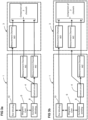
- the fluxgate transducer comprises more than one measurement channel, including a first measurement channel provided by the PWM signal controlling the excitation coil switching, and a second measurement channel provided by a connection to the excitation coils measuring the current in the excitation coils and processing this analog measurement signal in the microcontroller after conversion by an analog to digital (ADC) circuit 18.
- ADC analog to digital
- the operation of the PWM module may include the following modes:
- the duty cycle applied by the PWM module can be either fixed or variable.
- the fluxgate device 2 may further include a test winding 10 wound around the magnetic core 6, in addition to the winding(s) of the excitation coil.
- This test winding increases the diagnostic coverage of the transducer allowing to attain a high safety standard, such as the highest ASIL Level, in a simple architecture.
- a high safety standard such as the highest ASIL Level
- the test winding may be connected to a connection interface 44 of the fluxgate transducer for connection to an electronic circuit of a user system 3.
- the electronic circuit of the user system is configured to inject a test current into the test winding and to verify the measurement output of the fluxgate transducer to check the accuracy and proper functioning of the transducer.
- the measurement outputs from both the PWM measurement channel (the first measurement channel M1) and the analog measurement channel (the second measurement channel M2) may be checked with respect to an expected measurement value corresponding to the injected test current, and / or compared with each other.
- test current in a test winding is a good way to validate that the sensor operates properly at the time of the test.
- a problem e.g. loss of accuracy due to component drift
- the injection of current in a test winding is not a redundant path as it is only used during specific time periods and intervals (before start-up) but not used during nominal operation of the sensor.
- a test winding could be operated and controlled by the user system to check linearity of the fluxgate transducer measurement output over the operating range, however this test procedure must be performed faster than the required reaction time of the fluxgate transducer. The bigger the operating range, the longer the duration of the linearity check, which would require reducing the reaction time of the fluxgate transducer in order to be able to carry out the check.
- the user system may also or alternatively use the test winding to verify a DC tripping curve and an AC tripping curve, but not necessarily the linearity.
- the user system injects a current in the test winding and measures the duration required by the sensor to trip.
- the test winding is configured to be used during operation of the fluxgate transducer to provide a further measurement channel (a third measurement channel M3).
- the test winding may be connected to a signal processing circuit in the user system 3 that performs a PWM measurement (similar to the PWM measurement included in the fluxgate transducer).
- the test winding voltage has a square wave shape with a duty-cycle that varies proportionally to the leakage current.
- the user system measures the duty-cycle e.g. using zero crossings of the test winding voltage, whereby a comparator can be used to detect the 0V transitions.
- the fluxgate transducer may be configured to compute internally a comparison of the analog and PWM measurement channels M1, M2 which already provides a first level of safety, and the measurement output by the fluxgate transducer may then be compared to the measurement computed in the user system from the signal of the test winding, providing a second level of safety.
- any common mode causes of failure or faulty operation of the fluxgate transducer due for instance by faults in the magnetic core or the excitation coil may be checked by other diagnostics, such as
- the channel measurements at the user side are preferably PWM measurements as these do not interfere with each other when compared with analog measurement.
- the two windings forming the center tapped excitation coil preferably have the same number of turns, however the number of turns of the test winding may be different to the number of turns of the excitation coil.
- the test winding may advantageously have more turns in order to have higher voltage.
- the proposed safety architecture can be synthesized in providing a fluxgate transducer with windings accessible by the user system that can be used either to inject a test current and test transducer internal measurement channels or as external measurement channels directly connected to the user system.
- An advantage of the test winding configuration of the present invention is to mutualize a single element for both injecting a current for testing of the transducer, and measuring the primary current in an additional (redundant) channel for safety.
- the bandwidth and reaction time of the measurement channel at the user system side is equivalent to the fluxgate transducer when compared to a reduced bandwidth in the case the test winding is used to test linearity over the full operating range in real time.
- a circuit of the user system injects a current in the test winding and verifies the measurement. If the measurement is successful, then the circuit of the user system activates the measurement on the test winding.
- the user system uses the test winding to inject a current in the fluxgate transducer.
- the user system injects current in the test winding and verifies that the values injected correspond to those measured by the measurement channel internal to the transducer.
- the user system can also measure the PWM directly on the test winding while injecting the current.
- the user system performs a comparison of the current injected as measured in the user system and as measured in the fluxgate transducer. If the comparison is below a predefined threshold, it means that test winding is working properly as well as the fluxgate transducer internal measurement channels.
- the fluxgate transducer may include a sequence to reset the magnetic circuit to a deterministic one that permit to ensure that the magnetic offset of the fluxgate transducer remain the one set-up during the calibration.
- This sequence may advantageously be operated in the following situations:
- the fluxgate magnetic core auto-oscillates at a certain frequency, for instance at 20kHz, with substantially constant flux densities at saturation +Hsat and -Hsat.
- the fixed frequency controlled by the PWM module 28 is set at a lower value (for instance 5kHz in this example), which leads to the fluxgate magnetic core having variable (uncontrolled) flux densities +Hsat and -Hsat.
- this corresponds to switching from a high frequency hysteresis cycle with a defined depth of saturation where the flux densities +Hsat and -Hsat are set by the DAC value input of the comparator 24, to a low frequency hysteresis cycle with an undefined depth of saturation.
- a cause of this undefined depth of saturation is that the lower the frequency, the deeper the saturation, first, because the current can rise higher if the half cycles are longer given a high enough supply voltage to overcome the resistance of the current path, and second, because the core will stay longer in a saturated state even after the limited voltage does not allow a further increase of the current.
- the magnetic material will stop in an unknown state issued from a low frequency hysteresis cycle.
- the fluxgate transducer will start from this unknown state and stabilize rapidly at the high frequency auto-oscillating state, but the transition to the high frequency state does not recover totally the magnetic state of the magnetic material.
- the magnetic offset is partially affected by the switch off sequence. This difference comes from the fact that during normal auto-oscillating operation, the hysteresis cycle is swept at a high frequency, and during switch off the hysteresis cycle is swept at low frequency.
- the magnetic material exhibits different magnetic characteristics and hysteresis cycles when the frequency changes. This is also reinforced by the fact that the depth of saturation is different in both situations.
- a first solution to avoid starting from an unknown magnetization state of the magnetic core would be to prevent the operation of the fluxgate transducer at low frequency and stop oscillation as soon as the excitation signal voltage inputted into the comparator drops below a certain level that is higher than the DAC input value.
- the instant when the fluxgate transducer should be stopped should be deterministic in order to ensure the magnetic circuit remains always in the same state.
- a second and preferred solution includes performing a specific start-up sequence without verifying the stopped state of the fluxgate transducer in order to reset the magnetic state of the magnetic material to a defined one that would be deterministic.
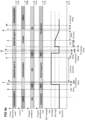
- FIG 4a An example of an advantageous sequence is illustrated in figure 4a .
- This sequence can be generalized as two sequences labelled DEGAUSS (Part 1) and DEGAUSS (Part 2).
- DEGAUSS in this sequence is not intended to represent a conventional degauss procedure where magnetic field and flux density equals to 0, but instead is intended to represent a demagnetization procedure imposing a deterministic magnetic state of the magnetic material (i.e. with a known or pre-defined magnetic offset).
- the method to reinitialize the magnetic state of the magnetic circuit can be used after power-up, over-load or after any scenario that may adversely affect the magnetic state of the magnetic material (e.g. closing a relay that charges capacitors with a high peak current).
- Switch S3 is open in order to limit the fluxgate saturation; S1 and S2 are closed alternatingly and opened when the comparator detects that the current passing through the second resistor R2 has increased to a value higher than determined by the output voltage of the DAC fed to the comparator input 16b. After each opening of the switches, a certain dead time determined by the PWM module passes after which the switch that had been open during the preceding half cycle is closed via the logic 30, e.g. using a flipflop.
- Step (a) The demagnetization procedure is started by the control circuit stopping the oscillation of the fluxgate device 2 by opening the excitation coil switches S1, S2 (i.e. set to off) at point (a).
- the bypass circuit switch S3 may also be actuated by the control circuit to close the switch (i.e. set to on), however in certain embodiments the bypass circuit switch S3 may be left open (i.e. remain set to off). Whether the bypass switch is actuated by being closed or left opened will depend on magnetic properties of the material used for the fluxgate core.
- the signal to the first input 16a of the comparator 24 is also kept constant as the excitation coil switches S1, S2 are opened, thus shutting off the comparator output signal.
- Step (b) The DAC 26 is then controlled by the signal processing module 43 to output a high amplitude first voltage signal, e.g. close to its maximum value (corresponding shut-off currents for the fluxgate so high that they cannot be reached). From instant d (end of the comparator delay point (d)) onwards, the fluxgate transducer is operated at a fixed frequency defined by configuration values in the PWM module, the number of half periods for this sequence being defined by the signal processing unit 43. The excitation current, as well as the depth of saturation, is naturally limited by the supply voltage and the circuit first resistor 12 and second resistor 20.
- the frequency must be lower than the minimum oscillation frequency reached during the switch off sequence, and the lower the better.
- this sequence can be time consuming for the start-up of the fluxgate transducer, the number of half periods and the duration of the overall sequence should be minimized, for instance less than ten half periods, for instance between one to five half periods.
- the current consumption of the fluxgate transducer is maximum or close to maximum during this sequence.
- the fluxgate core will be in a state of high magnetization in one or the other polarity depending on the polarity of the last half cycle that is well defined because of the sequence being the same each time it is applied.
- Step (e) The fixed frequency step is ended by the control circuit stopping the oscillation of the fluxgate device 2 by opening the excitation coil switches S1, S2 (i.e. set to off) at point (e).
- Step (f) The high amplitude first DAC voltage signal fed into the second input 16b of the comparator is set to a nominal voltage amplitude, which may be zero or a non-zero nominal voltage amplitude lower than said high amplitude voltage signal.
- Step ( i ) The DAC voltage signal fed into the second input 16b of the comparator is set to an intermediate high second voltage amplitude, which is greater than the nominal voltage amplitude and lower than said high amplitude first voltage signal.
- the fluxgate transducer is thus operated in auto-oscillating sequence where the saturation depth is slightly decreased from a high value to a nominal value. This procedure is available when the first resistor 12 is short circuited (switch S3 is closed) and the saturation depth is increased. As the fluxgate transducer operates in auto-oscillation, the excitation current is only increased during the saturation phase of the magnetic core and power consumption is reduced compared to the previous sequence (although still higher than in nominal operating mode).
- Step ( j ) After a short sequence at the intermediate high second voltage amplitude (point ( j )) the amplitude of the DAC voltage signal fed into the second input 16b of the comparator is progressively reduced over a slope duration back to the nominal voltage (point (k)).
- Step ( k ) - The bypass circuit switch S3 may also be actuated by the control circuit to open the switch (i.e. set to off), however in certain embodiments the bypass circuit switch S3 may be left closed (i.e. remain set to on). Whether the bypass switch is actuated by being opened or left closed will depend on the magnetic properties of the material used for the fluxgate core.
- Figure 4b illustrates a magnetic offset of a fluxgate transducer without using the above described sequences (upper plot) and with use of the above described sequences (lower plot). It can be seen in the upper plot that without use of the proposed start-up sequence, there is a greater range of magnetization values leading to a magnetic offset that is undetermined and that cannot be accurately compensated for in the measurement output. In the lower plot with use of the proposed start-up sequence, there is a much smaller range of magnetization values, allowing to define a magnetic offset that can be compensated for with greater accuracy in the measurement output.
Landscapes
- Physics & Mathematics (AREA)
- General Physics & Mathematics (AREA)
- Engineering & Computer Science (AREA)
- Power Engineering (AREA)
- Measuring Magnetic Variables (AREA)
- Measuring Instrument Details And Bridges, And Automatic Balancing Devices (AREA)
Claims (14)
- Fluxgate-Stromwandler (2), der eine Steuerschaltung (4) und eine Fluxgate-Vorrichtung (2) umfasst, die einen sättigbaren weichmagnetischen Kern (6) umfasst, der von einer Erregerspule (8) umgeben ist, wobei die Steuerschaltung eine Erregerspulen-Antriebsschaltung umfasst, die mit der Erregerspule verbunden ist und dazu ausgestaltet ist, ein magnetisches Wechselfeld zum abwechselnden Sättigen des weichmagnetischen Kerns zu erzeugen, wobei die Erregerspule eine erste Wicklung (8a) und eine zweite Wicklung (8b) umfasst, die an einem gemeinsamen Punkt (9) miteinander verbunden sind, der einen Eingang der ersten Wicklung und einen Ausgang der zweiten Wicklung bildet, wobei die erste Wicklung mit einem ersten Schalter (S1) in Reihe geschaltet ist und die zweite Wicklung mit einem zweiten Schalter (S2) in Reihe geschaltet ist, der erste und der zweite Schalter von der Steuerschaltung gesteuert werden, um einen Erregerspulenstrom in der ersten Wicklung, der ein Magnetfeld in dem Magnetkern in einer ersten Richtung erzeugt, und einen Erregerspulenstrom in der zweiten Wicklung bereitzustellen, der ein Magnetfeld in dem Magnetkern in einer zweiten Richtung erzeugt, die der ersten Richtung entgegengesetzt ist,
dadurch gekennzeichnet, dass der Fluxgate-Wandler mit einem Benutzersystem (3) verbunden ist, um gemeinsam ein Strommesssystem zu bilden, das mindestes drei Messkanäle, einen ersten PWM-Kanal M1, einen zweiten analogen Kanal M2 und einen dritten Kanal M3, aufweist, der von der Testwicklung (10) bereitgestellt wird, wobei das Benutzersystem dazu ausgestaltet ist, einen Vergleich der Messsignale von den drei Messkanälen zu berechnen, um einen korrekten oder fehlerhaften Betrieb zu bestimmen. - Fluxgate-Stromwandler nach dem vorhergehenden Anspruch, wobei die Steuerschaltung einen Komparator (24) umfasst, der einen ersten Eingang (16a) umfasst, der nach dem ersten und dem zweiten Schalter mit der Erregerspule verbunden ist.
- Fluxgate-Stromwandler nach dem vorhergehenden Anspruch, wobei ein zweiter Eingang des Komparators mit einem DAC (16b) verbunden ist, der eine anpassbare Bezugsspannung zum Anpassen des Ausgangspegels des Komparators liefert.
- Fluxgate-Stromwandler nach einem der zwei direkt vorhergehenden Ansprüche, wobei die Steuerschaltung ein PWM-Modul (28) umfasst, das mit einem Ausgang des Komparators verbunden ist und dazu ausgestaltet ist, einen Zeitpunkt der Betätigung des ersten und des zweiten Schalters zu steuern, welche das Einführen einer Totzeit zwischen dem Schalten von einer Erregerspulenwicklung zur anderen Erregerspulenwicklung umfasst.
- Fluxgate-Stromwandler nach dem vorhergehenden Anspruch, der ferner eine kombinatorische und sequentielle Logikzelle (30) umfasst, die mit einem Ausgang eines PWM-Moduls (28) zur Erzeugung ergänzender Signale verbunden ist, die von dem PWM-Modul bereitgestellte Totzeit umfassen.
- Fluxgate-Stromwandler nach einem der zwei direkt vorhergehenden Ansprüche, der ein Erfassungsmodul (32) umfasst, das mit einem Ausgang des PWM-Moduls (28) zum Erfassen des Zeitpunkts der Schaltsignale verbunden ist.
- Fluxgate-Stromwandler nach einem der vorhergehenden Ansprüche, wobei der Wandler einen analogen Messkanal (M2) umfasst, der nach dem ersten und dem zweiten Schalter mit der Erregerspule verbunden ist und ein ADC-Modul (18) umfasst.
- Fluxgate-Stromwandler nach dem vorhergehenden Anspruch, wobei der analoge Messkanal ferner einen DAC (26) umfasst, der mit dem ADC-Modul verbunden ist und ferner mit einem Eingang (16b) eines Komparators (24) verbunden ist, der einen ersten Eingang (16a) aufweist, der mit der Erregerspule verbunden ist.
- Fluxgate-Stromwandler nach dem vorhergehenden Anspruch, wobei der analoge Messkanal ferner einen Verstärker (42) zum Erhöhen der Verstärkung und Skalieren eines Versatzes der Messung des in das ADC-Modul eingespeisten Signals umfasst.
- Fluxgate-Stromwandler nach einem der vorhergehenden Ansprüche, wobei die Steuerschaltung ferner einen ersten Widerstand (12) umfasst, der auf einer High-Side der Fluxgate-Vorrichtung verbunden ist, wobei die Steuerschaltung ferner einen dritten Schalter S3 umfasst, der in einer Bypass-Schaltung (14) parallel zum ersten Widerstand platziert ist und dazu ausgestaltet ist, den ersten Widerstand kurzzuschließen, wenn der Schalter in die geschlossene Position geschaltet wird.
- Fluxgate-Stromwandler nach dem vorhergehenden Anspruch, wobei der analoge Messkanal eine Bezugsspannungsquelle zum Steuern einer Versorgungsbezugsspannung für das ADC-Modul umfasst.
- Fluxgate-Stromwandler nach einem der vorhergehenden Anspruche, der ferner eine Testwicklung (10) umfasst, die um den Magnetkern (6) gewickelt ist, wobei die Testwicklung mit einer Verbindungsschnittstelle (44) des Fluxgate-Transistors zur Verbindung mit einer elektronischen Schaltung eines Benutzersystems (3) verbunden ist.
- Fluxgate-Stromwandler nach dem vorhergehenden Anspruch, wobei die Testwicklung dazu ausgestaltet ist, einen Teststrom von dem Benutzersystem (3) zu empfangen und eine Spannung an das Benutzersystem (3) in einem zweiten Betriebsmodus auszugeben, die einem Messignal des Magnetfelds der Fluxgate-Vorrichtung entspricht, derart dass die Testwicklung einen dritten Messkanal M3 bereitstellt.
- Fluxgate-Stromwandler nach einem der vorhergehenden Ansprüche, wobei die elektronische Schaltung des Benutzersystems (3) dazu ausgestaltet ist, zwei der drei Messignale zu verwenden, die Werte aufweisen, die am nächsten beieinander liegen, und das andere Messignal im Fall eines Fehlers zu verwerfen, der einen der Messkanäle beeinträchtigt.
Priority Applications (3)
| Application Number | Priority Date | Filing Date | Title |
|---|---|---|---|
| EP24172076.2A EP4379398B1 (de) | 2021-07-20 | 2022-07-15 | Fluxgate-wandler zur strommessung |
| EP24172078.8A EP4400850B1 (de) | 2021-07-20 | 2022-07-15 | Fluxgate-wandler zur strommessung |
| EP24172077.0A EP4400849B1 (de) | 2021-07-20 | 2022-07-15 | Fluxgate-wandler zur strommessung |
Applications Claiming Priority (2)
| Application Number | Priority Date | Filing Date | Title |
|---|---|---|---|
| EP21186819.5A EP4123317A1 (de) | 2021-07-20 | 2021-07-20 | Fluxgate-wandler zur strommessung |
| PCT/EP2022/069946 WO2023001719A2 (en) | 2021-07-20 | 2022-07-15 | Fluxgate transducer for current sensing |
Related Child Applications (6)
| Application Number | Title | Priority Date | Filing Date |
|---|---|---|---|
| EP24172076.2A Division-Into EP4379398B1 (de) | 2021-07-20 | 2022-07-15 | Fluxgate-wandler zur strommessung |
| EP24172076.2A Division EP4379398B1 (de) | 2021-07-20 | 2022-07-15 | Fluxgate-wandler zur strommessung |
| EP24172077.0A Division EP4400849B1 (de) | 2021-07-20 | 2022-07-15 | Fluxgate-wandler zur strommessung |
| EP24172077.0A Division-Into EP4400849B1 (de) | 2021-07-20 | 2022-07-15 | Fluxgate-wandler zur strommessung |
| EP24172078.8A Division-Into EP4400850B1 (de) | 2021-07-20 | 2022-07-15 | Fluxgate-wandler zur strommessung |
| EP24172078.8A Division EP4400850B1 (de) | 2021-07-20 | 2022-07-15 | Fluxgate-wandler zur strommessung |
Publications (3)
| Publication Number | Publication Date |
|---|---|
| EP4374180A2 EP4374180A2 (de) | 2024-05-29 |
| EP4374180B1 true EP4374180B1 (de) | 2025-04-02 |
| EP4374180C0 EP4374180C0 (de) | 2025-04-02 |
Family
ID=76999776
Family Applications (5)
| Application Number | Title | Priority Date | Filing Date |
|---|---|---|---|
| EP21186819.5A Withdrawn EP4123317A1 (de) | 2021-07-20 | 2021-07-20 | Fluxgate-wandler zur strommessung |
| EP24172078.8A Active EP4400850B1 (de) | 2021-07-20 | 2022-07-15 | Fluxgate-wandler zur strommessung |
| EP24172077.0A Active EP4400849B1 (de) | 2021-07-20 | 2022-07-15 | Fluxgate-wandler zur strommessung |
| EP22743493.3A Active EP4374180B1 (de) | 2021-07-20 | 2022-07-15 | Fluxgate-wandler zur strommessung |
| EP24172076.2A Active EP4379398B1 (de) | 2021-07-20 | 2022-07-15 | Fluxgate-wandler zur strommessung |
Family Applications Before (3)
| Application Number | Title | Priority Date | Filing Date |
|---|---|---|---|
| EP21186819.5A Withdrawn EP4123317A1 (de) | 2021-07-20 | 2021-07-20 | Fluxgate-wandler zur strommessung |
| EP24172078.8A Active EP4400850B1 (de) | 2021-07-20 | 2022-07-15 | Fluxgate-wandler zur strommessung |
| EP24172077.0A Active EP4400849B1 (de) | 2021-07-20 | 2022-07-15 | Fluxgate-wandler zur strommessung |
Family Applications After (1)
| Application Number | Title | Priority Date | Filing Date |
|---|---|---|---|
| EP24172076.2A Active EP4379398B1 (de) | 2021-07-20 | 2022-07-15 | Fluxgate-wandler zur strommessung |
Country Status (5)
| Country | Link |
|---|---|
| US (4) | US12203964B2 (de) |
| EP (5) | EP4123317A1 (de) |
| JP (1) | JP7577893B2 (de) |
| CN (4) | CN119044576A (de) |
| WO (1) | WO2023001719A2 (de) |
Families Citing this family (2)
| Publication number | Priority date | Publication date | Assignee | Title |
|---|---|---|---|---|
| KR20240025409A (ko) * | 2022-08-18 | 2024-02-27 | 엘지이노텍 주식회사 | 이그니션 웨이크업 회로 |
| CN120275699B (zh) * | 2025-06-12 | 2025-08-22 | 宁德时代润智软件科技有限公司 | 电流传感器及其控制方法 |
Family Cites Families (16)
| Publication number | Priority date | Publication date | Assignee | Title |
|---|---|---|---|---|
| US4276510A (en) * | 1979-05-16 | 1981-06-30 | General Electric Company | Apparatus for sensing current transformer primary current as a function of differential core inductance |
| US4899103A (en) * | 1987-07-16 | 1990-02-06 | Brooktree Corporation | Current meter |
| US5161311A (en) * | 1990-08-29 | 1992-11-10 | Alps Electric Inc. | Calibration and compensation of an electronic compass system |
| US6294954B1 (en) * | 1999-09-23 | 2001-09-25 | Audiologic, Incorporated | Adaptive dead time control for switching circuits |
| US6346817B1 (en) * | 2000-04-27 | 2002-02-12 | Multitel Inc. | Float current measuring probe and method |
| JP2007139459A (ja) | 2005-11-15 | 2007-06-07 | Japan Aviation Electronics Industry Ltd | フラックスゲート型地磁気センサ |
| US7834613B2 (en) * | 2007-10-30 | 2010-11-16 | Power-One, Inc. | Isolated current to voltage, voltage to voltage converter |
| US7876086B2 (en) * | 2008-02-28 | 2011-01-25 | International Components Corporation | Current measuring device for measuring the electrical current flowing in an electrical conductor electrically isolated from the current measuring device |
| JP6123275B2 (ja) | 2012-12-17 | 2017-05-10 | 富士電機機器制御株式会社 | 電流検知装置 |
| JP6298581B2 (ja) * | 2013-09-30 | 2018-03-20 | 東日本旅客鉄道株式会社 | 電流検出装置及びこれを備えた変電設備 |
| CA2868663C (en) * | 2013-10-21 | 2016-11-08 | Tomasz Barczyk | Methods and systems relating to ac current measurements |
| US9618541B1 (en) * | 2016-04-20 | 2017-04-11 | Neilsen-Kuljian, Inc. | Apparatus, method and device for sensing DC currents |
| CN108333412B (zh) * | 2018-01-30 | 2021-05-14 | 宜昌市瑞磁科技有限公司 | 一种具有固定频率的pwm输出模式的电流检测装置及方法 |
| US11804679B2 (en) * | 2018-09-07 | 2023-10-31 | Cilag Gmbh International | Flexible hand-switch circuit |
| KR102111489B1 (ko) * | 2019-01-07 | 2020-05-15 | 주식회사 쓰리윈 | 에너지 저장 장치용 전력 모니터링 장치 |
| CN111119868B (zh) * | 2019-12-26 | 2021-07-06 | 中国石油大学(北京) | 井下磁场随钻探测装置 |
-
2021
- 2021-07-20 EP EP21186819.5A patent/EP4123317A1/de not_active Withdrawn
-
2022
- 2022-07-15 CN CN202411204036.1A patent/CN119044576A/zh active Pending
- 2022-07-15 US US18/580,691 patent/US12203964B2/en active Active
- 2022-07-15 EP EP24172078.8A patent/EP4400850B1/de active Active
- 2022-07-15 WO PCT/EP2022/069946 patent/WO2023001719A2/en not_active Ceased
- 2022-07-15 CN CN202280060230.XA patent/CN117916604B/zh active Active
- 2022-07-15 EP EP24172077.0A patent/EP4400849B1/de active Active
- 2022-07-15 EP EP22743493.3A patent/EP4374180B1/de active Active
- 2022-07-15 JP JP2024503695A patent/JP7577893B2/ja active Active
- 2022-07-15 EP EP24172076.2A patent/EP4379398B1/de active Active
- 2022-07-15 CN CN202411203921.8A patent/CN119044575A/zh active Pending
- 2022-07-15 CN CN202411203918.6A patent/CN119044574A/zh active Pending
-
2024
- 2024-10-02 US US18/904,405 patent/US20250020698A1/en active Pending
- 2024-10-02 US US18/904,402 patent/US20250020697A1/en active Pending
- 2024-10-02 US US18/904,401 patent/US20250020696A1/en active Pending
Also Published As
| Publication number | Publication date |
|---|---|
| EP4400849A2 (de) | 2024-07-17 |
| EP4379398B1 (de) | 2025-03-26 |
| EP4379398A3 (de) | 2024-10-09 |
| WO2023001719A2 (en) | 2023-01-26 |
| EP4374180C0 (de) | 2025-04-02 |
| CN117916604A (zh) | 2024-04-19 |
| EP4400849C0 (de) | 2025-09-03 |
| US20250020697A1 (en) | 2025-01-16 |
| WO2023001719A3 (en) | 2023-03-09 |
| JP7577893B2 (ja) | 2024-11-05 |
| JP2024526913A (ja) | 2024-07-19 |
| CN119044575A (zh) | 2024-11-29 |
| US20250020698A1 (en) | 2025-01-16 |
| US12203964B2 (en) | 2025-01-21 |
| US20250020696A1 (en) | 2025-01-16 |
| EP4379398C0 (de) | 2025-03-26 |
| EP4379398A2 (de) | 2024-06-05 |
| EP4374180A2 (de) | 2024-05-29 |
| EP4400849A3 (de) | 2024-10-30 |
| EP4123317A1 (de) | 2023-01-25 |
| CN117916604B (zh) | 2025-03-25 |
| CN119044574A (zh) | 2024-11-29 |
| US20240264204A1 (en) | 2024-08-08 |
| EP4400850A2 (de) | 2024-07-17 |
| CN119044576A (zh) | 2024-11-29 |
| EP4400850C0 (de) | 2025-05-21 |
| EP4400849B1 (de) | 2025-09-03 |
| EP4400850B1 (de) | 2025-05-21 |
| EP4400850A3 (de) | 2024-10-30 |
Similar Documents
| Publication | Publication Date | Title |
|---|---|---|
| US20250020696A1 (en) | Fluxgate current transducer with an analog measurement channel | |
| CN113406531B (zh) | 一种漏电检测装置、漏电检测方法和充电设备 | |
| TWI338993B (en) | Sampling circuit and detecting circuit for power converter | |
| EP2593799B1 (de) | Strommessgerät und verfahren zur strommessung dafür | |
| US20240085495A1 (en) | Circuit for alternating current and direct current leakage detection | |
| US20120140531A1 (en) | Flyback primary side output voltage sensing system and method | |
| US11977119B2 (en) | Solenoid system with position and temperature detection | |
| CN115053144A (zh) | 用于改进的电流传感器的方法和系统 | |
| CN115616442A (zh) | 检测装置、逆变器及检测方法 | |
| JP2012182920A (ja) | 電流センサ制御装置 | |
| EP2741416B1 (de) | Verfahren zur berechnung der motorkonstante eines permanentmagnet-synchronelektromotors und vorrichtung zur berechnung der motorkonstante | |
| Yang et al. | Analysis and design of a self-oscillating bidirectionally saturated fluxgate current sensor | |
| CN109844546B (zh) | 电流传感器 | |
| KR20130089161A (ko) | 공진 회로의 제어 장치 작동 방법 및 제어 장치 | |
| CN113514689A (zh) | 用于电绝缘、ac/dc灵敏差动电流测量的装置及方法 | |
| US5814983A (en) | Method for sensing DC current and sensor for carrying out same | |
| Román et al. | Low consumption flux-gate transducer for AC and DC high-current measurement | |
| EP1171776A1 (de) | Schaltung mit verbessertem dynamischen Verhalten zur Strommessung in pulsbreitmodulierten Verstärkern | |
| KR20060023993A (ko) | 스위치 모드 전원 회로 및 하드 스위칭 진폭의 측정치 생성방법 | |
| Liu et al. | A novel method for measuring current derivative signal with closed loop hall-effect current sensor | |
| CN120913980A (zh) | 一种退磁循环电路、系统及方法 | |
| US7498804B1 (en) | Resonance current sensing | |
| CN119717999A (zh) | 一种零磁通数字直流电流传感器闭环控制方法 | |
| CN112234903A (zh) | 车辆驱动装置及其方法 | |
| JP2001264371A (ja) | 活線絶縁測定装置 |
Legal Events
| Date | Code | Title | Description |
|---|---|---|---|
| STAA | Information on the status of an ep patent application or granted ep patent |
Free format text: STATUS: UNKNOWN |
|
| STAA | Information on the status of an ep patent application or granted ep patent |
Free format text: STATUS: THE INTERNATIONAL PUBLICATION HAS BEEN MADE |
|
| PUAI | Public reference made under article 153(3) epc to a published international application that has entered the european phase |
Free format text: ORIGINAL CODE: 0009012 |
|
| STAA | Information on the status of an ep patent application or granted ep patent |
Free format text: STATUS: REQUEST FOR EXAMINATION WAS MADE |
|
| 17P | Request for examination filed |
Effective date: 20240201 |
|
| AK | Designated contracting states |
Kind code of ref document: A2 Designated state(s): AL AT BE BG CH CY CZ DE DK EE ES FI FR GB GR HR HU IE IS IT LI LT LU LV MC MK MT NL NO PL PT RO RS SE SI SK SM TR |
|
| DAV | Request for validation of the european patent (deleted) | ||
| DAX | Request for extension of the european patent (deleted) | ||
| GRAP | Despatch of communication of intention to grant a patent |
Free format text: ORIGINAL CODE: EPIDOSNIGR1 |
|
| STAA | Information on the status of an ep patent application or granted ep patent |
Free format text: STATUS: GRANT OF PATENT IS INTENDED |
|
| INTG | Intention to grant announced |
Effective date: 20241209 |
|
| GRAS | Grant fee paid |
Free format text: ORIGINAL CODE: EPIDOSNIGR3 |
|
| GRAA | (expected) grant |
Free format text: ORIGINAL CODE: 0009210 |
|
| STAA | Information on the status of an ep patent application or granted ep patent |
Free format text: STATUS: THE PATENT HAS BEEN GRANTED |
|
| AK | Designated contracting states |
Kind code of ref document: B1 Designated state(s): AL AT BE BG CH CY CZ DE DK EE ES FI FR GB GR HR HU IE IS IT LI LT LU LV MC MK MT NL NO PL PT RO RS SE SI SK SM TR |
|
| REG | Reference to a national code |
Ref country code: GB Ref legal event code: FG4D |
|
| REG | Reference to a national code |
Ref country code: CH Ref legal event code: EP |
|
| REG | Reference to a national code |
Ref country code: IE Ref legal event code: FG4D |
|
| REG | Reference to a national code |
Ref country code: DE Ref legal event code: R096 Ref document number: 602022012653 Country of ref document: DE |
|
| U01 | Request for unitary effect filed |
Effective date: 20250402 |
|
| U07 | Unitary effect registered |
Designated state(s): AT BE BG DE DK EE FI FR IT LT LU LV MT NL PT RO SE SI Effective date: 20250409 |
|
| U20 | Renewal fee for the european patent with unitary effect paid |
Year of fee payment: 4 Effective date: 20250520 |
|
| PG25 | Lapsed in a contracting state [announced via postgrant information from national office to epo] |
Ref country code: ES Free format text: LAPSE BECAUSE OF FAILURE TO SUBMIT A TRANSLATION OF THE DESCRIPTION OR TO PAY THE FEE WITHIN THE PRESCRIBED TIME-LIMIT Effective date: 20250402 |
|
| PG25 | Lapsed in a contracting state [announced via postgrant information from national office to epo] |
Ref country code: NO Free format text: LAPSE BECAUSE OF FAILURE TO SUBMIT A TRANSLATION OF THE DESCRIPTION OR TO PAY THE FEE WITHIN THE PRESCRIBED TIME-LIMIT Effective date: 20250702 Ref country code: GR Free format text: LAPSE BECAUSE OF FAILURE TO SUBMIT A TRANSLATION OF THE DESCRIPTION OR TO PAY THE FEE WITHIN THE PRESCRIBED TIME-LIMIT Effective date: 20250703 |
|
| PG25 | Lapsed in a contracting state [announced via postgrant information from national office to epo] |
Ref country code: PL Free format text: LAPSE BECAUSE OF FAILURE TO SUBMIT A TRANSLATION OF THE DESCRIPTION OR TO PAY THE FEE WITHIN THE PRESCRIBED TIME-LIMIT Effective date: 20250402 |
|
| PG25 | Lapsed in a contracting state [announced via postgrant information from national office to epo] |
Ref country code: HR Free format text: LAPSE BECAUSE OF FAILURE TO SUBMIT A TRANSLATION OF THE DESCRIPTION OR TO PAY THE FEE WITHIN THE PRESCRIBED TIME-LIMIT Effective date: 20250402 |
|
| PGFP | Annual fee paid to national office [announced via postgrant information from national office to epo] |
Ref country code: CH Payment date: 20250801 Year of fee payment: 4 |
|
| PG25 | Lapsed in a contracting state [announced via postgrant information from national office to epo] |
Ref country code: RS Free format text: LAPSE BECAUSE OF FAILURE TO SUBMIT A TRANSLATION OF THE DESCRIPTION OR TO PAY THE FEE WITHIN THE PRESCRIBED TIME-LIMIT Effective date: 20250702 |
|
| PG25 | Lapsed in a contracting state [announced via postgrant information from national office to epo] |
Ref country code: IS Free format text: LAPSE BECAUSE OF FAILURE TO SUBMIT A TRANSLATION OF THE DESCRIPTION OR TO PAY THE FEE WITHIN THE PRESCRIBED TIME-LIMIT Effective date: 20250802 |
|
| PG25 | Lapsed in a contracting state [announced via postgrant information from national office to epo] |
Ref country code: SM Free format text: LAPSE BECAUSE OF FAILURE TO SUBMIT A TRANSLATION OF THE DESCRIPTION OR TO PAY THE FEE WITHIN THE PRESCRIBED TIME-LIMIT Effective date: 20250402 |
|
| PG25 | Lapsed in a contracting state [announced via postgrant information from national office to epo] |
Ref country code: CZ Free format text: LAPSE BECAUSE OF FAILURE TO SUBMIT A TRANSLATION OF THE DESCRIPTION OR TO PAY THE FEE WITHIN THE PRESCRIBED TIME-LIMIT Effective date: 20250402 |
|
| PG25 | Lapsed in a contracting state [announced via postgrant information from national office to epo] |
Ref country code: SK Free format text: LAPSE BECAUSE OF FAILURE TO SUBMIT A TRANSLATION OF THE DESCRIPTION OR TO PAY THE FEE WITHIN THE PRESCRIBED TIME-LIMIT Effective date: 20250402 |
|
| PLBE | No opposition filed within time limit |
Free format text: ORIGINAL CODE: 0009261 |
|
| STAA | Information on the status of an ep patent application or granted ep patent |
Free format text: STATUS: NO OPPOSITION FILED WITHIN TIME LIMIT |
|
| REG | Reference to a national code |
Ref country code: CH Ref legal event code: L10 Free format text: ST27 STATUS EVENT CODE: U-0-0-L10-L00 (AS PROVIDED BY THE NATIONAL OFFICE) Effective date: 20260211 |
|
| 26N | No opposition filed |
Effective date: 20260105 |