EP4372343A1 - Replacement system and replacement method for metallurgical temperature measuring and sampling probe - Google Patents
Replacement system and replacement method for metallurgical temperature measuring and sampling probe Download PDFInfo
- Publication number
- EP4372343A1 EP4372343A1 EP22863453.1A EP22863453A EP4372343A1 EP 4372343 A1 EP4372343 A1 EP 4372343A1 EP 22863453 A EP22863453 A EP 22863453A EP 4372343 A1 EP4372343 A1 EP 4372343A1
- Authority
- EP
- European Patent Office
- Prior art keywords
- temperature measuring
- clamping
- sampling probe
- jaw
- positioning
- Prior art date
- Legal status (The legal status is an assumption and is not a legal conclusion. Google has not performed a legal analysis and makes no representation as to the accuracy of the status listed.)
- Pending
Links
Images



Classifications
-
- G—PHYSICS
- G01—MEASURING; TESTING
- G01K—MEASURING TEMPERATURE; MEASURING QUANTITY OF HEAT; THERMALLY-SENSITIVE ELEMENTS NOT OTHERWISE PROVIDED FOR
- G01K13/00—Thermometers specially adapted for specific purposes
- G01K13/12—Thermometers specially adapted for specific purposes combined with sampling devices for measuring temperatures of samples of materials
- G01K13/125—Thermometers specially adapted for specific purposes combined with sampling devices for measuring temperatures of samples of materials for siderurgical purposes
-
- G—PHYSICS
- G01—MEASURING; TESTING
- G01K—MEASURING TEMPERATURE; MEASURING QUANTITY OF HEAT; THERMALLY-SENSITIVE ELEMENTS NOT OTHERWISE PROVIDED FOR
- G01K1/00—Details of thermometers not specially adapted for particular types of thermometer
- G01K1/14—Supports; Fastening devices; Arrangements for mounting thermometers in particular locations
-
- G—PHYSICS
- G01—MEASURING; TESTING
- G01K—MEASURING TEMPERATURE; MEASURING QUANTITY OF HEAT; THERMALLY-SENSITIVE ELEMENTS NOT OTHERWISE PROVIDED FOR
- G01K1/00—Details of thermometers not specially adapted for particular types of thermometer
- G01K1/08—Protective devices, e.g. casings
-
- G—PHYSICS
- G01—MEASURING; TESTING
- G01K—MEASURING TEMPERATURE; MEASURING QUANTITY OF HEAT; THERMALLY-SENSITIVE ELEMENTS NOT OTHERWISE PROVIDED FOR
- G01K7/00—Measuring temperature based on the use of electric or magnetic elements directly sensitive to heat ; Power supply therefor, e.g. using thermoelectric elements
- G01K7/02—Measuring temperature based on the use of electric or magnetic elements directly sensitive to heat ; Power supply therefor, e.g. using thermoelectric elements using thermoelectric elements, e.g. thermocouples
-
- G—PHYSICS
- G01—MEASURING; TESTING
- G01N—INVESTIGATING OR ANALYSING MATERIALS BY DETERMINING THEIR CHEMICAL OR PHYSICAL PROPERTIES
- G01N1/00—Sampling; Preparing specimens for investigation
- G01N1/02—Devices for withdrawing samples
- G01N1/10—Devices for withdrawing samples in the liquid or fluent state
- G01N1/12—Dippers; Dredgers
- G01N1/125—Dippers; Dredgers adapted for sampling molten metals
-
- Y—GENERAL TAGGING OF NEW TECHNOLOGICAL DEVELOPMENTS; GENERAL TAGGING OF CROSS-SECTIONAL TECHNOLOGIES SPANNING OVER SEVERAL SECTIONS OF THE IPC; TECHNICAL SUBJECTS COVERED BY FORMER USPC CROSS-REFERENCE ART COLLECTIONS [XRACs] AND DIGESTS
- Y02—TECHNOLOGIES OR APPLICATIONS FOR MITIGATION OR ADAPTATION AGAINST CLIMATE CHANGE
- Y02P—CLIMATE CHANGE MITIGATION TECHNOLOGIES IN THE PRODUCTION OR PROCESSING OF GOODS
- Y02P10/00—Technologies related to metal processing
- Y02P10/20—Recycling
Definitions
- the present invention relates to a metallurgical technology, in particular to a replacement system and replacement method for a metallurgical temperature measuring and sampling probe.
- a rod-shaped temperature measuring and sampling probe with a temperature measuring and sampling function sleeves a vertically moving temperature measuring and sampling gun (hereinafter referred to as a temperature measuring gun), the temperature measuring gun together with the temperature measuring and sampling probe is inserted into a large ladle (a container) loaded with liquid molten metal by a conveying mechanism, the top of the probe is equipped with a thermocouple for temperature measurement of molten metal, while the molten metal enters a steel die through a sampling port of the probe.
- the probe leaves the large ladle the metal solidifies into a solid sample in the steel die.
- the sample needs to be sent to an analysis chamber for measurement of parameters such as its chemical composition after being taken out.
- the temperature measuring and sampling probe is mainly composed of two sections of paper long circular tubes, divided into a clamping section and a sampling section.
- the metal sample body formed by solidification must be separated in time from the sampling section of the temperature measuring and sampling probe.
- the temperature measuring and sampling probe manually sleeves the temperature measuring gun, the temperature measuring gun carries the temperature measuring and sampling probe to enter a large ladle loaded with molten metal to complete the temperature measuring and sampling operation, and then is lifted, and an operator pulls out the probe from the temperature measuring gun and strikes the paper tube in the sampling section to take out the metal sample body. Due to the probe body which is mostly in a burning state during manual operation, and the heavy smoke and dust generated by steelmaking and the high temperature of the large ladle, damage is caused to the physical health of operators.
- An existing replacement method for a temperature measuring and sampling probe such as Chinese patent application No. CN201922259240.4 discloses "an automatic insertion and pulling-out device for robot temperature measuring and sampling", which includes a sampling device, an automatic gripping device, a sampling rod storage device, and a to-be-tested product storage device.
- an automatic sampling and storage process is achieved. A specific structural form and technical details of a gripping device are not described in this solution.
- Chinese patent application No. CN201811613127.5 discloses "an automatic abutting joint device for a temperature measuring probe and a temperature measuring gun".
- the automatic abutting joint device includes an opening-angle manipulator and a translational manipulator which are respectively fixed to a frame, the frame is disposed on a manipulator, two semi-conical plates are respectively fixed to two clamping fingers of the opening-angle manipulator, when the clamping fingers of the opening-angle manipulator are in a clamping closed state, the two semi-conical plates are in abutting joint together to form a conical cylinder, the axis of the conical cylinder is perpendicular to a positioning plate, and the positioning plate is provided with a position sensor.
- the position sensor mounted in this patent cannot detect the position of the probe in a clamping jaw nor the axis of the temperature measuring gun, possibly affecting the abutting joint operation.
- An object of the present invention is to provide a replacement system and replacement method for a metallurgical temperature measuring and sampling probe, which can reduce the labor intensity of operators, reduce the harm of the high-risk environment to health of the operators, and improve the working efficiency instead of manually sleeving or pulling out the temperature measuring and sampling probe.
- the replacement system further includes a safety protection fence enclosing the temperature measuring gun, the six-axis manipulator, the shelf, the shearing machine and the waste material box.
- the clamping jaw includes: a left support arm, a right support arm, and a translational cylinder which can drive the left support arm and the right support arm to move in opposite directions, a left clamping block disposed at an end of the left support arm, and a right clamping block disposed at an end of the right support arm, and a V-shaped or trapezoidal groove is disposed in a center of each of opposite sides of the left clamping block and right clamping block along an axial direction; and the left clamping block and the right clamping block have a length which is 3-4 times an outer diameter of the clamping segment of the temperature measuring and sampling probe.
- the left support arm and the right support arm have a C-shaped structure.
- both sides in the V-shaped or trapezoidal groove of the left clamping block are evenly provided with a plurality of trenches at intervals
- both sides in the V-shaped or trapezoidal groove of the right clamping block are evenly provided with a plurality of trenches at intervals
- each trench has a depth of 5-10 mm, and a spacing between the adjacent trenches is 30-40 mm.
- the positioning jaw includes an opening-angle cylinder, and a left positioning finger and a right positioning finger which are arranged on two swing arms of the opening-angle cylinder, wherein the left positioning finger and the right positioning finger each include a base portion and a clamping portion located at a front end of the base portion, each clamping portion is V-shaped, and an inner bottom portion of each clamping portion is an arc-shaped concave surface; preferably, inner sides of V-shaped two ends of each clamping portion are each provided with an arc-shaped chamfer; and an inner diameter of a positioning space enclosed by cross closure of the left positioning finger and the right positioning finger is matched with an outer diameter of the body of the temperature measuring gun, and a center line of the positioning space enclosed by the cross closure of the left positioning finger and the right positioning finger and a center line of a clamping space formed by closure of the left clamping block and the right clamping block of the clamping jaw are the same straight line.
- the detection device is a non-contact ranging sensor, preferably a laser sensor.
- a replacement method of the replacement system for the metallurgical temperature measuring and sampling probe according to the present invention includes the steps of:
- the left positioning finger and the right positioning finger of the positioning jaw are closed again, and if the left positioning finger and the right positioning finger of the positioning jaw are completely closed, then it is further confirmed that the temperature measuring and sampling probe has been completely pulled out from the temperature measuring gun.
- the replacement method of the present invention is compared with the existing replacement methods for a temperature measuring and sampling probe:
- a replacement system for a metallurgical temperature measuring and sampling probe is arranged at a temperature measuring gun 100 for measuring the temperature of a molten metal ladle, and includes a six-axis manipulator 1, a clamping tool 2 mounted at a tail end of the six-axis manipulator 1, a shelf 3 for storing a temperature measuring and sampling probe 200, a shearing machine 4 configured to cut a sampling segment 201 and a clamping segment 202 of the temperature measuring and sampling probe 200 apart, and a waste material box 5 (as shown in a dashed box in FIG. 1 ).
- molten metal ladle can be understood as a container containing molten metal.
- the replacement system may not be provided with the waste material box 5.
- the replacement system for the metallurgical temperature measuring and sampling probe of the present invention is used to allow the temperature measuring and sampling probe 200 to cooperate with the temperature measuring gun 100, so that the temperature measuring and sampling probe 200 performs temperature measuring and sampling on the molten metal ladle, and after completion of temperature measuring and sampling, the temperature measuring and sampling probe 200 is separated from the temperature measuring gun 100, so that the shearing machine 4 cuts the sampling segment 201 and the clamping segment 202 of the temperature measuring and sampling probe 200, and the cut sampling segment 201 is used for subsequent analysis.
- the temperature measuring gun 100, the shelf 3, the shearing machine 4, and the waste material box 5 are sequentially arranged in different directions within a rotation range of the six-axis manipulator 1, respectively, wherein the waste material box 5 is arranged close to the shearing machine 4.
- the six-axis manipulator 1, the clamping tool 2, the shelf 3 and the shearing machine 4 are in a plane provided with a temperature measuring and sampling hole 7, and the molten metal ladle is located below the temperature measuring and sampling hole 7 (i.e., in a direction perpendicular to a paper surface), in other words, the molten metal ladle is not in the same plane as the above components.
- Both sides of the temperature measuring gun 100 are provided with sliding mechanisms (as shown in FIG. 1 , the sliding mechanisms may be pulleys) capable of clamping the temperature measuring gun 100 and driving the temperature measuring gun 100 to move up and down in the direction perpendicular to the paper surface.
- the temperature measuring and sampling probe 200 is of a round rod type, and is provided with a sampling segment 201 and a clamping segment 202, wherein the clamping segment 202 is of a hollow structure and is provided with an opening for allowing the temperature measuring gun 100 to insert; and the temperature measuring gun 100 is of a round rod type and includes a head 101 and a body 102, a diameter of the head 101 is smaller than a diameter of the body 102, and a a gradual transition section 103 is formed between the head 101 and the body 102.
- the temperature measuring gun 100 When the temperature measuring gun 100 is inserted into the temperature measuring and sampling probe 200 for a certain depth, the temperature measuring gun 100 is electrically connected to the temperature measuring and sampling probe 200, and at this time, the temperature of molten metal can be measured by a thermocouple located on the sampling segment 201.
- the clamping tool 2 includes a base 21, a clamping jaw 22 configured to clamp the temperature measuring and sampling probe 200 and a positioning jaw 23 which are arranged in parallel at a front end of the base 21, and a detection device 24 located between the clamping jaw 22 and the positioning jaw 23, and a detection source of the detection device 24, a center line of a clamping space of the clamping jaw 22, and a center line of a positioning space of the positioning jaw 23 are located on the same axis.
- the positioning jaw 23 does not clamp the head 101 of the temperature measuring gun 100, but limits the head 101 of the temperature measuring gun 100 in a positioning space, so that the temperature measuring gun 100 cannot move to a space outside the positioning space.
- the replacement system for the metallurgical temperature measuring and sampling probe of the present invention further includes a safety protection fence 6 enclosing the temperature measuring gun 100, the six-axis manipulator 1, the shelf 3, the shearing machine 4 and the waste material box 5.
- the clamping jaw 22 includes a left support arm 221, a right support arm 222, a translational cylinder 223 (a radial gripper) which can drive the left support arm 221 and the right support arm 222 to move in opposite directions, a left clamping block 224 disposed at an end of the left support arm 221, and a right clamping block 225 disposed at an end of the right support arm 222.
- a V-shaped or trapezoidal groove 2241 is disposed in a center of each of opposite sides of the left clamping block 224 and the right clamping block 225 in an axial direction.
- the left clamping block 224 and the right clamping block 225 have a length which is 3-4 times an outer diameter of the clamping segment 202 of the temperature measuring and sampling probe 200.
- the left support arm 221 and the right support arm 222 have a C-shaped structure.
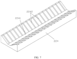
- both sides in the V-shaped or trapezoidal groove 2241 of the left clamping block 224 are evenly provided with a plurality of trenches 2242 at intervals
- both sides in the V-shaped or trapezoidal groove 2241 of the right clamping block 225 are evenly provided with a plurality of trenches 2242 at intervals (taking the left clamping block 224 as an example, the same below).
- each trench 2242 has a depth of 5-10 mm, and a spacing between the adjacent trenches 2242 is 30-40 mm.
- a spacing between the adjacent trenches 2242 is 30 mm.
- the base 21 of the clamping tool 2 is a metal frame, a front end face of which is planar.
- the positioning jaw 23 includes an opening-angle cylinder 231, and a left positioning finger 232 and a right positioning finger 233 which are arranged on two swing arms of the opening-angle cylinder 231.
- the left positioning finger 232 and the right positioning finger 233 each include a base portion 2321 (taking the left positioning finger 232 as an example, the same below) and a clamping portion 2322 located at a front end of the base portion 2321.
- Each clamping portion 2322 is V-shaped, and an inner bottom portion 23221 of each clamping portion 2322 is an arc-shaped concave surface.
- each clamping portion 2322 is each provided with an arc-shaped chamfer 23222.
- a positioning space 230 enclosed by cross closure of the left positioning finger 232 and the right positioning finger 233 is matched with an outer diameter of the body 102 of the temperature measuring gun 100, and a center line of the positioning space 230 enclosed by the cross closure of the left positioning finger 232 and the right positioning finger 233 and a center line of a clamping space 220 formed by closure of the left clamping block 224 and the right clamping block 225 of the clamping jaw 22 are located on the same axis, and the detection source of the detection device 24 passes through the axis.
- the detection device 24 is a non-contact ranging sensor, preferably a laser sensor.
- a replacement method of the replacement system for the metallurgical temperature measuring and sampling probe includes the steps of:
- a replacement method of the replacement system for the metallurgical temperature measuring and sampling probe includes the steps:
- the left positioning finger 232 and the right positioning finger 233 of the positioning jaw 23 are closed again, and if the left positioning finger 232 and the right positioning finger 233 of the positioning jaw are completely closed, then it is further confirmed that the temperature measuring and sampling probe 200 has been completely pulled out from the temperature measuring gun 100.
Landscapes
- Physics & Mathematics (AREA)
- General Physics & Mathematics (AREA)
- Life Sciences & Earth Sciences (AREA)
- Hydrology & Water Resources (AREA)
- Health & Medical Sciences (AREA)
- Chemical & Material Sciences (AREA)
- Analytical Chemistry (AREA)
- Biochemistry (AREA)
- General Health & Medical Sciences (AREA)
- Immunology (AREA)
- Pathology (AREA)
- Sampling And Sample Adjustment (AREA)
- Waste-Gas Treatment And Other Accessory Devices For Furnaces (AREA)
Abstract
Description
- The present invention relates to a metallurgical technology, in particular to a replacement system and replacement method for a metallurgical temperature measuring and sampling probe.
- In processes such as steelmaking and continuous casting in a steel metallurgy process, it is necessary to extract a metal solution sample body from a metal solution and analyze parameters such as its chemical composition based on the sample. When the metal solution sample body is extracted, in general, a rod-shaped temperature measuring and sampling probe with a temperature measuring and sampling function sleeves a vertically moving temperature measuring and sampling gun (hereinafter referred to as a temperature measuring gun), the temperature measuring gun together with the temperature measuring and sampling probe is inserted into a large ladle (a container) loaded with liquid molten metal by a conveying mechanism, the top of the probe is equipped with a thermocouple for temperature measurement of molten metal, while the molten metal enters a steel die through a sampling port of the probe. When the probe leaves the large ladle, the metal solidifies into a solid sample in the steel die. The sample needs to be sent to an analysis chamber for measurement of parameters such as its chemical composition after being taken out.
- Typically, the temperature measuring and sampling probe is mainly composed of two sections of paper long circular tubes, divided into a clamping section and a sampling section. In order to analyze the metal composition in the ladle in real time, the metal sample body formed by solidification must be separated in time from the sampling section of the temperature measuring and sampling probe. Currently, the temperature measuring and sampling probe manually sleeves the temperature measuring gun, the temperature measuring gun carries the temperature measuring and sampling probe to enter a large ladle loaded with molten metal to complete the temperature measuring and sampling operation, and then is lifted, and an operator pulls out the probe from the temperature measuring gun and strikes the paper tube in the sampling section to take out the metal sample body. Due to the probe body which is mostly in a burning state during manual operation, and the heavy smoke and dust generated by steelmaking and the high temperature of the large ladle, damage is caused to the physical health of operators.
- An existing replacement method for a temperature measuring and sampling probe, such as Chinese patent application No.
CN201922259240.4 - Chinese patent application No.
CN201811613127.5 - An object of the present invention is to provide a replacement system and replacement method for a metallurgical temperature measuring and sampling probe, which can reduce the labor intensity of operators, reduce the harm of the high-risk environment to health of the operators, and improve the working efficiency instead of manually sleeving or pulling out the temperature measuring and sampling probe.
- To achieve the above object, the technical solution of the present invention is as follows:
- a replacement system for a metallurgical temperature measuring and sampling probe is arranged at a temperature measuring gun for measuring the temperature of a molten metal ladle, and includes: a six-axis manipulator, a clamping tool mounted at a tail end of the six-axis manipulator, a shelf for storing the temperature measuring and sampling probe, a shearing machine configured to cut a sampling segment and a clamping segment of the temperature measuring and sampling probe apart, and a waste material box; wherein,
- the temperature measuring gun, the shelf, the shearing machine, and the waste material box are sequentially arranged in different directions within a rotation range of the six-axis manipulator, respectively, wherein the waste material box is arranged close to the shearing machine;
- the temperature measuring and sampling probe is of a round rod type, and is provided with a sampling segment and a clamping segment, wherein the clamping segment is of a hollow structure and is provided with an opening for allowing the temperature measuring gun to insert; and the temperature measuring gun is of a round rod type, a diameter of a head of the temperature measuring gun is smaller than a diameter of a body of the temperature measuring gun, and a gradual transition section is formed between the head and the body; and
- the clamping tool includes a base, a clamping jaw configured to clamp the temperature measuring and sampling probe and a positioning jaw which are arranged in parallel at a front end of the base, and a detection device located between the clamping jaw and the positioning jaw, a center line of a positioning space of the positioning jaw and a center line of a clamping space of the clamping jaw are located on the same axis, and a detection source of the detection device passes through the axis.
- Further, the replacement system further includes a safety protection fence enclosing the temperature measuring gun, the six-axis manipulator, the shelf, the shearing machine and the waste material box.
- Preferably, the clamping jaw includes: a left support arm, a right support arm, and a translational cylinder which can drive the left support arm and the right support arm to move in opposite directions, a left clamping block disposed at an end of the left support arm, and a right clamping block disposed at an end of the right support arm, and a V-shaped or trapezoidal groove is disposed in a center of each of opposite sides of the left clamping block and right clamping block along an axial direction; and the left clamping block and the right clamping block have a length which is 3-4 times an outer diameter of the clamping segment of the temperature measuring and sampling probe.
- Preferably, the left support arm and the right support arm have a C-shaped structure.
- Preferably, both sides in the V-shaped or trapezoidal groove of the left clamping block are evenly provided with a plurality of trenches at intervals, and both sides in the V-shaped or trapezoidal groove of the right clamping block are evenly provided with a plurality of trenches at intervals, and
preferably, each trench has a depth of 5-10 mm, and a spacing between the adjacent trenches is 30-40 mm. - Preferably, the positioning jaw includes an opening-angle cylinder, and a left positioning finger and a right positioning finger which are arranged on two swing arms of the opening-angle cylinder, wherein the left positioning finger and the right positioning finger each include a base portion and a clamping portion located at a front end of the base portion, each clamping portion is V-shaped, and an inner bottom portion of each clamping portion is an arc-shaped concave surface; preferably, inner sides of V-shaped two ends of each clamping portion are each provided with an arc-shaped chamfer; and an inner diameter of a positioning space enclosed by cross closure of the left positioning finger and the right positioning finger is matched with an outer diameter of the body of the temperature measuring gun, and a center line of the positioning space enclosed by the cross closure of the left positioning finger and the right positioning finger and a center line of a clamping space formed by closure of the left clamping block and the right clamping block of the clamping jaw are the same straight line.
- Preferably, the detection device is a non-contact ranging sensor, preferably a laser sensor.
- A replacement method of the replacement system for the metallurgical temperature measuring and sampling probe according to the present invention includes the steps of:
- 1) driving the clamping tool to be close to the temperature measuring gun by the six-axis manipulator, scanning and detecting a position of the temperature measuring gun with the detection device on the clamping tool, then moving the clamping tool to the shelf, grabbing the clamping segment of the temperature measuring and sampling probe with the clamping jaw on the clamping tool, and confirming whether a position of the temperature measuring and sampling probe in the clamping jaw of the clamping tool is located at an axis with the detection device;
- 2) driving the temperature measuring and sampling probe to be close to the head of the temperature measuring gun by the six-axis manipulator, performing cross closure on the left positioning finger and the right positioning finger of the positioning jaw to enclose the head of the temperature measuring gun in a positioning space enclosed by the left positioning finger and the right positioning finger, then grabbing the temperature measuring and sampling probe by the clamping jaw to sleeve the head of the temperature measuring gun, when the head of the temperature measuring gun enters the clamping segment of the temperature measuring and sampling probe for at least 30 mm, allowing the left positioning finger and the right positioning finger of the positioning jaw to release the temperature measuring gun, and then driving the temperature measuring and sampling probe to complete sleeving the temperature measuring gun by the six-axis manipulator; and then allowing the six-axis manipulator to be detached from the temperature measuring gun, and driving the temperature measuring and sampling probe to descend and enter the molten metal ladle by the temperature measuring gun to detect the temperature of molten metal and take a molten metal sample;
- 3) after completion of temperature measuring and sampling operations, allowing the temperature measuring gun to ascend, driving the clamping tool to be close to an upper portion of the temperature measuring gun by the six-axis manipulator, allowing the left positioning finger and the right positioning finger of the positioning jaw to move in opposite directions to grasp and position the upper portion of the temperature measuring gun, then allowing the left clamping block and the right clamping block of the clamping jaw to move in opposite directions to clamp the clamping segment of the temperature measuring and sampling probe, then allowing the left positioning finger and the right positioning finger of the positioning jaw to release the temperature measuring gun, and pulling out the temperature measuring and sampling probe from the temperature measuring gun by the clamping jaw under the drive of the six-axis manipulator; and
- 4) driving the clamping tool to feed the sampling segment of the temperature measuring and sampling probe into the shearing machine by the six-axis manipulator, after cutting off the sampling segment of the temperature measuring and sampling probe, driving the clamping tool to bring the clamping segment of the temperature measuring and sampling probe to the waste material box by the six-axis manipulator while allowing the left clamping block and the right clamping block of the clamping jaw to be separated to throw the clamping segment of the temperature measuring and sampling probe into the waste material box, and allowing the six-axis manipulator to return to a standby position.
- Preferably, after pulling out the temperature measuring and sampling probe from the temperature measuring gun by the clamping jaw under the drive of the six-axis manipulator in the step 3), the left positioning finger and the right positioning finger of the positioning jaw are closed again, and if the left positioning finger and the right positioning finger of the positioning jaw are completely closed, then it is further confirmed that the temperature measuring and sampling probe has been completely pulled out from the temperature measuring gun.
- The replacement method of the present invention is compared with the existing replacement methods for a temperature measuring and sampling probe:
- Chinese patent application No.
CN201922259240.4 - Chinese patent application No.
CN201811613127.5 - The beneficial effects of the present invention are as follows:
- 1) in the present invention, the six-axis manipulator is used to cooperate with the clamping tool to realize a plurality of operations such as picking, storing, sleeving, pulling out, and post-processing of the temperature measuring and sampling probe, the operation surface is compact, the efficiency is high, and the operation can be continuously performed for a long time.
- 2) In the clamping tool according to the present invention, the left positioning finger and the right positioning finger of the positioning jaw have a V-shaped structure with an arc-shaped concave surface at an inner bottom portion thereof, and the left positioning finger and the right positioning finger are in cross arrangement up and down when the positioning jaw is closed, thereby performing a larger positioning range with a smaller structure size.
- 3) In the present invention, the detection device is disposed between the positioning jaw and the clamping jaw, which can not only directly detect the position of the temperature measuring and sampling probe in the clamping jaw, but also can measure the axis posture and end position of the temperature measuring gun in a process of allowing the clamping tool to be close to different orientations of the temperature measuring gun, effectively expanding the function of the clamping tool, while also improving the clamping stability and reliability.
- 4) Both sides in the V-shaped or trapezoidal groove in each of the left clamping block and the right clamping block of the clamping jaw of the clamping tool in the present invention are provided with the trenches, so that the clamping stability of clamping the temperature measuring and sampling probe can be effectively improved, particularly after the surface of the clamping segment of the temperature measuring and sampling probe after completion of temperature measuring and sampling is carbonized, edges of the trenches can crush a carbonized layer, and carbon slag can be led out of the trenches, thereby effectively improving the friction force of the surfaces of the clamping blocks.
-
-
FIG. 1 is a schematic plan layout view of a replacement system according to the present invention; -
FIG. 2 is a perspective view of a six-axis manipulator and a clamping tool according to an embodiment of the present invention; -
FIG. 3 is a perspective view of a clamping tool according to an embodiment of the present invention; -
FIG. 4 is a schematic structural diagram of a positioning jaw according to an embodiment of the present invention; -
FIG. 5 is a schematic diagram of a use state of the positioning jaw according to the embodiment of the present invention; -
FIG. 6 is a schematic diagram of a use state of a clamping jaw according to an embodiment of the present invention; -
FIG. 7 is a schematic diagram of a left clamping block according to an embodiment of the present invention; -
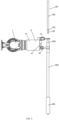
FIG. 8 is a first schematic diagram in which a temperature measuring and sampling probe is clamped by a clamping tool to be ready to sleeve a temperature measuring gun in an embodiment of the present invention; -
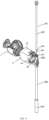
FIG. 9 is a second schematic diagram in which a temperature measuring and sampling probe is clamped by a clamping tool to be ready to sleeve a temperature measuring gun in an embodiment of the present invention; and -
FIG. 10 is a third schematic diagram in which a temperature measuring and sampling probe is clamped by a clamping tool to sleeve a temperature measuring gun in an embodiment of the present invention. - Referring to
FIGS. 1 to 7 , a replacement system for a metallurgical temperature measuring and sampling probe provided by the present invention is arranged at atemperature measuring gun 100 for measuring the temperature of a molten metal ladle, and includes a six-axis manipulator 1, aclamping tool 2 mounted at a tail end of the six-axis manipulator 1, ashelf 3 for storing a temperature measuring andsampling probe 200, ashearing machine 4 configured to cut asampling segment 201 and aclamping segment 202 of the temperature measuring andsampling probe 200 apart, and a waste material box 5 (as shown in a dashed box inFIG. 1 ). - It should be noted that the molten metal ladle can be understood as a container containing molten metal.
- In other embodiments, the replacement system may not be provided with the
waste material box 5. The replacement system for the metallurgical temperature measuring and sampling probe of the present invention is used to allow the temperature measuring andsampling probe 200 to cooperate with thetemperature measuring gun 100, so that the temperature measuring andsampling probe 200 performs temperature measuring and sampling on the molten metal ladle, and after completion of temperature measuring and sampling, the temperature measuring andsampling probe 200 is separated from thetemperature measuring gun 100, so that the shearingmachine 4 cuts thesampling segment 201 and theclamping segment 202 of the temperature measuring andsampling probe 200, and thecut sampling segment 201 is used for subsequent analysis. Thetemperature measuring gun 100, theshelf 3, the shearingmachine 4, and thewaste material box 5 are sequentially arranged in different directions within a rotation range of the six-axis manipulator 1, respectively, wherein thewaste material box 5 is arranged close to the shearingmachine 4. - It should be noted that the six-
axis manipulator 1, theclamping tool 2, theshelf 3 and the shearingmachine 4 are in a plane provided with a temperature measuring and sampling hole 7, and the molten metal ladle is located below the temperature measuring and sampling hole 7 (i.e., in a direction perpendicular to a paper surface), in other words, the molten metal ladle is not in the same plane as the above components. Both sides of thetemperature measuring gun 100 are provided with sliding mechanisms (as shown inFIG. 1 , the sliding mechanisms may be pulleys) capable of clamping thetemperature measuring gun 100 and driving thetemperature measuring gun 100 to move up and down in the direction perpendicular to the paper surface. - Referring to
FIGS. 8 and9 , the temperature measuring andsampling probe 200 is of a round rod type, and is provided with asampling segment 201 and aclamping segment 202, wherein theclamping segment 202 is of a hollow structure and is provided with an opening for allowing thetemperature measuring gun 100 to insert; and thetemperature measuring gun 100 is of a round rod type and includes ahead 101 and abody 102, a diameter of thehead 101 is smaller than a diameter of thebody 102, and a agradual transition section 103 is formed between thehead 101 and thebody 102. - When the
temperature measuring gun 100 is inserted into the temperature measuring andsampling probe 200 for a certain depth, thetemperature measuring gun 100 is electrically connected to the temperature measuring andsampling probe 200, and at this time, the temperature of molten metal can be measured by a thermocouple located on thesampling segment 201. - The
clamping tool 2 includes abase 21, a clampingjaw 22 configured to clamp the temperature measuring andsampling probe 200 and apositioning jaw 23 which are arranged in parallel at a front end of thebase 21, and adetection device 24 located between the clampingjaw 22 and thepositioning jaw 23, and a detection source of thedetection device 24, a center line of a clamping space of the clampingjaw 22, and a center line of a positioning space of thepositioning jaw 23 are located on the same axis. - It should be noted that the
positioning jaw 23 does not clamp thehead 101 of thetemperature measuring gun 100, but limits thehead 101 of thetemperature measuring gun 100 in a positioning space, so that thetemperature measuring gun 100 cannot move to a space outside the positioning space. - Further, with reference to
FIG. 1 , the replacement system for the metallurgical temperature measuring and sampling probe of the present invention further includes a safety protection fence 6 enclosing thetemperature measuring gun 100, the six-axis manipulator 1, theshelf 3, the shearingmachine 4 and thewaste material box 5. - Preferably, with reference to
FIG. 2 and in combination withFIG. 7 , the clampingjaw 22 includes aleft support arm 221, aright support arm 222, a translational cylinder 223 (a radial gripper) which can drive theleft support arm 221 and theright support arm 222 to move in opposite directions, aleft clamping block 224 disposed at an end of theleft support arm 221, and aright clamping block 225 disposed at an end of theright support arm 222. A V-shaped ortrapezoidal groove 2241 is disposed in a center of each of opposite sides of theleft clamping block 224 and theright clamping block 225 in an axial direction. Theleft clamping block 224 and theright clamping block 225 have a length which is 3-4 times an outer diameter of theclamping segment 202 of the temperature measuring andsampling probe 200. Theleft support arm 221 and theright support arm 222 have a C-shaped structure. - Preferably, with reference to
FIG. 7 , both sides in the V-shaped ortrapezoidal groove 2241 of theleft clamping block 224 are evenly provided with a plurality oftrenches 2242 at intervals, and both sides in the V-shaped ortrapezoidal groove 2241 of theright clamping block 225 are evenly provided with a plurality oftrenches 2242 at intervals (taking theleft clamping block 224 as an example, the same below). Preferably, eachtrench 2242 has a depth of 5-10 mm, and a spacing between theadjacent trenches 2242 is 30-40 mm. - Preferably, a spacing between the
adjacent trenches 2242 is 30 mm. - Preferably, with reference to
FIGS. 2 ,3 and8 to 10 , thebase 21 of theclamping tool 2 is a metal frame, a front end face of which is planar. - Preferably, with reference to
FIG. 4 in combination withFIGS. 5 and 6 , thepositioning jaw 23 includes an opening-angle cylinder 231, and aleft positioning finger 232 and aright positioning finger 233 which are arranged on two swing arms of the opening-angle cylinder 231. Theleft positioning finger 232 and theright positioning finger 233 each include a base portion 2321 (taking theleft positioning finger 232 as an example, the same below) and aclamping portion 2322 located at a front end of thebase portion 2321. Each clampingportion 2322 is V-shaped, and aninner bottom portion 23221 of each clampingportion 2322 is an arc-shaped concave surface. Preferably, inner sides of V-shaped two ends of each clampingportion 2322 are each provided with an arc-shapedchamfer 23222. Apositioning space 230 enclosed by cross closure of theleft positioning finger 232 and theright positioning finger 233 is matched with an outer diameter of thebody 102 of thetemperature measuring gun 100, and a center line of thepositioning space 230 enclosed by the cross closure of theleft positioning finger 232 and theright positioning finger 233 and a center line of a clampingspace 220 formed by closure of theleft clamping block 224 and theright clamping block 225 of the clampingjaw 22 are located on the same axis, and the detection source of thedetection device 24 passes through the axis. - Preferably, the
detection device 24 is a non-contact ranging sensor, preferably a laser sensor. - Referring to
FIGS. 1 to 10 , a replacement method of the replacement system for the metallurgical temperature measuring and sampling probe according to the present invention includes the steps of: - 1) driving the
clamping tool 2 to be close to thetemperature measuring gun 100 by the six-axis manipulator 1, scanning and detecting a position of thetemperature measuring gun 100 with thedetection device 24 on theclamping tool 2, then moving theclamping tool 2 to theshelf 3, grabbing theclamping segment 202 of the temperature measuring andsampling probe 200 with the clampingjaw 22 on theclamping tool 2, and confirming whether a position of the temperature measuring andsampling probe 200 in the clampingjaw 22 of theclamping tool 2 is located at an axis with thedetection device 24; - 2) driving the temperature measuring and
sampling probe 200 to be close to thehead 101 of thetemperature measuring gun 100 by the six-axis manipulator 1, performing cross closure on theleft positioning finger 232 and theright positioning finger 233 of thepositioning jaw 23 to enclose thehead 101 of thetemperature measuring gun 100 in a positioning space enclosed by theleft positioning finger 232 and theright positioning finger 233, then grabbing the temperature measuring andsampling probe 200 by the clampingjaw 22 to sleeve thehead 101 of thetemperature measuring gun 100, when thehead 101 of thetemperature measuring gun 100 enters theclamping segment 202 of the temperature measuring andsampling probe 200 for at least 30 mm, allowing theleft positioning finger 232 and theright positioning finger 233 of thepositioning jaw 23 to release thetemperature measuring gun 100, and then driving the temperature measuring andsampling probe 200 to complete sleeving thetemperature measuring gun 100 by the six-axis manipulator; and then allowing the six-axis manipulator 1 to be detached from thetemperature measuring gun 100, and driving the temperature measuring andsampling probe 200 to descend and enter the molten metal ladle by thetemperature measuring gun 100 to detect the temperature of molten metal and take a molten metal sample; - 3) after completion of temperature measuring and sampling operations, allowing the
temperature measuring gun 100 to ascend, driving theclamping tool 2 to be close to an upper portion of thetemperature measuring gun 100 by the six-axis manipulator 1, allowing theleft positioning finger 232 and theright positioning finger 233 of thepositioning jaw 23 to move in opposite directions to grasp and position the upper portion of thetemperature measuring gun 100, then allowing theleft clamping block 224 and theright clamping block 225 of the clampingjaw 22 to move in opposite directions to clamp theclamping segment 202 of the temperature measuring andsampling probe 200, then allowing theleft positioning finger 232 and theright positioning finger 233 of thepositioning jaw 23 to release thetemperature measuring gun 100, and pulling out the temperature measuring andsampling probe 200 from thetemperature measuring gun 100 by the clampingjaw 22 under the drive of the six-axis manipulator 1; and - 4) driving the
clamping tool 2 to feed thesampling segment 201 of the temperature measuring andsampling probe 200 into the shearingmachine 4 by the six-axis manipulator 1, after cutting off thesampling segment 201 of the temperature measuring andsampling probe 200, driving theclamping tool 2 to bring theclamping segment 202 of the temperature measuring andsampling probe 200 to thewaste material box 5 by the six-axis manipulator 1 while allowing theleft clamping block 224 and theright clamping block 225 of the clampingjaw 22 to be separated to throw the clampingsegment 202 of the temperature measuring andsampling probe 200 into thewaste material box 5, and allowing the six-axis manipulator 1 to return to a standby position. - Referring to
FIGS. 1 to 10 , a replacement method of the replacement system for the metallurgical temperature measuring and sampling probe according to the present invention includes the steps: - 1) the
clamping tool 2 is driven to be close to thetemperature measuring gun 100 by the six-axis manipulator 1, a position of thetemperature measuring gun 100 is scanned and detected with thedetection device 24 on theclamping tool 2, then theclamping tool 2 is moved to theshelf 3 for storing the temperature measuring andsampling probe 200, one end of theclamping segment 202 of the temperature measuring andsampling probe 200 is grabbed or clamped with the clampingjaw 22 on theclamping tool 2, and it is confirmed whether a position of the temperature measuring andsampling probe 200 in the clampingjaw 22 of theclamping tool 2 is located at an axis with thedetection device 24; - 2) the temperature measuring and
sampling probe 200 is driven to be close to thehead 101 of thetemperature measuring gun 100 by the six-axis manipulator 1, and cross closure is performed on theleft positioning finger 232 and theright positioning finger 233 of thepositioning jaw 23 to enclose thehead 101 of thetemperature measuring gun 100 in a positioning space enclosed by theleft positioning finger 232 and theright positioning finger 233, so that thehead 101 of thetemperature measuring gun 100 is limited in the positioning space for subsequently being sleeved with the temperature measuring andsampling probe 200. Thereafter, the six-axis manipulator 1 drives the temperature measuring andsampling probe 200 to sleeve thehead 101 of thetemperature measuring gun 100. As shown inFIG. 8 , thetemperature measuring gun 100 remains stationary and the temperature measuring andsampling probe 200 moves in a direction close to thehead 101 of thetemperature measuring gun 100 under the drive of the six-axis manipulator 1. When thehead 101 of thetemperature measuring gun 100 enters theclamping segment 202 of the temperature measuring andsampling probe 200 for at least 30 mm, theleft positioning finger 232 and theright positioning finger 233 of thepositioning jaw 23 release thetemperature measuring gun 100, and thereafter, the six-axis manipulator 1 drives the temperature measuring andsampling probe 200 to continue to perform sleeving until the temperature measuring andsampling probe 200 is electrically connected to thetemperature measuring gun 100 to complete the sleeving operation on thetemperature measuring gun 100. In other words, the six-axis manipulator 1 drives the temperature measuring andsampling probe 200 to continue to move upwards until sleeving thetemperature measuring gun 100 with the temperature measuring andsampling probe 200 is completed. Then, the six-axis manipulator 1 is detached from the temperature measuring gun 100 (e.g., after the six-axis manipulator 1 is detached from thetemperature measuring gun 100, the six-axis manipulator 1 can move to a standby position to prevent interference with the temperature measuring gun), and the temperature measuring gun 100 (e.g., under the drive of the sliding mechanisms) drives the temperature measuring andsampling probe 200 to descend and enter the molten metal ladle to detect the temperature of molten metal and take a molten metal sample; - 3) after completion of temperature measuring and sampling operations, the
temperature measuring gun 100 is allowed to ascend, the six-axis manipulator 1 drives theclamping tool 2 to be close to an upper portion of the temperature measuring gun 100 (i.e., the end, away from thehead 101, of the temperature measuring gun 100), and theleft positioning finger 232 and theright positioning finger 233 of thepositioning jaw 23 is allowed to move in opposite directions to grasp and position the upper portion of thetemperature measuring gun 100. Then theleft clamping block 224 and theright clamping block 225 of the clampingjaw 22 is allowed to move in opposite directions to clamp theclamping segment 202 of the temperature measuring andsampling probe 200, then theleft positioning finger 232 and theright positioning finger 233 of thepositioning jaw 23 release thetemperature measuring gun 100, and the temperature measuring andsampling probe 200 is pulled out from thetemperature measuring gun 100 by the clampingjaw 22 under the drive of the six-axis manipulator 1 (i.e., the temperature measuring andsampling probe 200 moves away from thetemperature measuring gun 100 under the drive of the six-axis manipulator 1 until the temperature measuring andsampling probe 200 is completely separated from the temperature measuring gun 100); and - 4) the six-
axis manipulator 1 drives theclamping tool 2 to feed thesampling segment 201 of the temperature measuring andsampling probe 200 into the shearingmachine 4, after cutting off thesampling segment 201 of the temperature measuring andsampling probe 200, the six-axis manipulator 1 drives theclamping tool 2 to bring theclamping segment 202 of the temperature measuring andsampling probe 200 to thewaste material box 5 while allowing theleft clamping block 224 and theright clamping block 225 of the clampingjaw 22 to be separated to throw the clampingsegment 202 of the temperature measuring andsampling probe 200 into thewaste material box 5, and the six-axis manipulator 1 is allowed to return to a standby position. - Preferably, after pulling out the temperature measuring and
sampling probe 200 from thetemperature measuring gun 100 by the clampingjaw 22 under the drive of the six-axis manipulator 1 in the step 3), theleft positioning finger 232 and theright positioning finger 233 of thepositioning jaw 23 are closed again, and if theleft positioning finger 232 and theright positioning finger 233 of the positioning jaw are completely closed, then it is further confirmed that the temperature measuring andsampling probe 200 has been completely pulled out from thetemperature measuring gun 100. - Those of ordinary skill in the art should realize that the above embodiments are merely used for illustrating the present invention and not intended to limit the present invention. Variations and modifications made to the above embodiments are intended to fall within the scope of the claims of the present invention as long as they fall within the spirit of the present invention.
Claims (12)
- A replacement system for a metallurgical temperature measuring and sampling probe, being arranged at a temperature measuring gun for measuring the temperature of a molten metal ladle, and characterized by comprising: a six-axis manipulator, a clamping tool mounted at a tail end of the six-axis manipulator, a shelf for storing the temperature measuring and sampling probe, a shearing machine and a waste material box; wherein,the temperature measuring gun, the shelf, the shearing machine, and the waste material box are sequentially arranged in different directions within a rotation range of the six-axis manipulator, respectively, wherein the waste material box is arranged close to the shearing machine;the temperature measuring and sampling probe is of a round rod type, and is provided with a sampling segment and a clamping segment, and the shearing machine is configured to cut the sampling segment and the clamping segment of the temperature measuring and sampling probe apart, wherein the clamping segment is of a hollow structure and is provided with an opening for allowing the temperature measuring gun to insert; and the temperature measuring gun is of a round rod type, a diameter of a head of the temperature measuring gun is smaller than a diameter of a body of the temperature measuring gun, and a gradual transition section is formed between the head and the body; andthe clamping tool comprises a base, a clamping jaw configured to clamp the temperature measuring and sampling probe and a positioning jaw which are arranged in parallel at a front end of the base, and a detection device located between the clamping jaw and the positioning jaw, a center line of a clamping space of the clamping jaw and a center line of a positioning space of the positioning jaw are located on the same axis, and a detection source of the detection device passes through the axis.
- The replacement system for the metallurgical temperature measuring and sampling probe according to claim 1, characterized by further comprising a safety protection fence enclosing the temperature measuring gun, the six-axis manipulator, the shelf, the shearing machine and the waste material box.
- The replacement system for the metallurgical temperature measuring and sampling probe according to claim 1, characterized in that the clamping jaw comprises: a left support arm, a right support arm, and a translational cylinder which can drive the left support arm and the right support arm to move in opposite directions, a left clamping block disposed at an end of the left support arm, and a right clamping block disposed at an end of the right support arm, and a V-shaped or trapezoidal groove is disposed in a center of each of opposite sides of the left clamping block and right clamping block along a length direction; and the left clamping block and the right clamping block have a length which is 3-4 times an outer diameter of the clamping segment of the temperature measuring and sampling probe.
- The replacement system for the metallurgical temperature measuring and sampling probe according to claim 3, characterized in that both sides in the V-shaped or trapezoidal groove of the left clamping block are evenly provided with a plurality of trenches at intervals, and both sides in the V-shaped or trapezoidal groove of the right clamping block are evenly provided with a plurality of trenches at intervals.
- The replacement system for the metallurgical temperature measuring and sampling probe according to claim 3 or 4, characterized in that the left support arm and the right support arm have a C-shaped structure.
- The replacement system for the metallurgical temperature measuring and sampling probe according to claim 1, characterized in that the positioning jaw comprises: an opening-angle cylinder, and a left positioning finger and a right positioning finger which are arranged on two swing arms of the opening-angle cylinder, wherein the left positioning finger and the right positioning finger each comprise a base portion and a clamping portion located at a front end of the base portion, each clamping portion is V-shaped, and an inner bottom portion of each clamping portion is an arc-shaped concave surface; and a range of a positioning space enclosed by cross closure of the left positioning finger and the right positioning finger is matched with an outer diameter of the body of the temperature measuring gun, and a center line of the positioning space enclosed by the cross closure of the left positioning finger and the right positioning finger and a center line of a clamping space formed by closure of the left clamping block and the right clamping block of the clamping jaw are located on the same axis.
- The replacement system for the metallurgical temperature measuring and sampling probe according to claim 1, characterized in that the detection device is a non-contact ranging sensor.
- The replacement system for the metallurgical temperature measuring and sampling probe according to claim 4, characterized in that each trench has a depth of 5-10 mm, and a spacing between the adjacent trenches is 30-40 mm.
- The replacement system for the metallurgical temperature measuring and sampling probe according to claim 6, characterized in that inner sides of V-shaped two ends of each clamping portion are each provided with an arc-shaped chamfer.
- The replacement system for the metallurgical temperature measuring and sampling probe according to claim 7, characterized in that the non-contact ranging sensor is a laser sensor.
- A replacement method of the replacement system for the metallurgical temperature measuring and sampling probe according to any one of claims 1 to 10, comprising the steps of:1) driving the clamping tool to be close to the temperature measuring gun by the six-axis manipulator, scanning and detecting a position of the temperature measuring gun with the detection device on the clamping tool, then moving the clamping tool to the shelf, grabbing the clamping segment of the temperature measuring and sampling probe with the clamping jaw on the clamping tool, and confirming whether a position of the temperature measuring and sampling probe in the clamping jaw of the clamping tool is located at an axis with the detection device;2) driving the temperature measuring and sampling probe to be close to the head of the temperature measuring gun by the six-axis manipulator, performing cross closure on the left positioning finger and the right positioning finger of the positioning jaw to enclose the head of the temperature measuring gun in a positioning space enclosed by the left positioning finger and the right positioning finger, then grabbing the temperature measuring and sampling probe by the clamping jaw to sleeve the head of the temperature measuring gun, when the head of the temperature measuring gun enters the clamping segment of the temperature measuring and sampling probe for at least 30 mm, allowing the left positioning finger and the right positioning finger of the positioning jaw to release the temperature measuring gun, and then driving the temperature measuring and sampling probe to complete sleeving the temperature measuring gun by the six-axis manipulator; and then allowing the six-axis manipulator to be detached from the temperature measuring gun, and driving the temperature measuring and sampling probe to descend and enter the molten metal ladle by the temperature measuring gun to detect the temperature of molten metal and take a molten metal sample;3) after completion of temperature measuring and sampling operations, allowing the temperature measuring gun to ascend, driving the clamping tool to be close to an upper portion of the temperature measuring gun by the six-axis manipulator, allowing the left positioning finger and the right positioning finger of the positioning jaw to move in opposite directions to grasp and position the upper portion of the temperature measuring gun, then allowing the left clamping block and the right clamping block of the clamping jaw to move in opposite directions to clamp the clamping segment of the temperature measuring and sampling probe, then allowing the left positioning finger and the right positioning finger of the positioning jaw to release the temperature measuring gun, and pulling out the temperature measuring and sampling probe from the temperature measuring gun by the clamping jaw under the drive of the six-axis manipulator; and4) driving the clamping tool to feed the sampling segment of the temperature measuring and sampling probe into the shearing machine by the six-axis manipulator, after cutting off the sampling segment of the temperature measuring and sampling probe, driving the clamping tool to bring the clamping segment of the temperature measuring and sampling probe to the waste material box by the six-axis manipulator while allowing the left clamping block and the right clamping block of the clamping jaw to be separated to throw the clamping segment of the temperature measuring and sampling probe into the waste material box, and allowing the six-axis manipulator to return to a standby position.
- The replacement method of the replacement system for the metallurgical temperature measuring and sampling probe according to claim 11, characterized in that after pulling out the temperature measuring and sampling probe from the temperature measuring gun by the clamping jaw under the drive of the six-axis manipulator in the step 3), the left positioning finger and the right positioning finger of the positioning jaw are closed again, and if the left positioning finger and the right positioning finger of the positioning jaw are completely closed, then it is further confirmed that the temperature measuring and sampling probe has been completely pulled out from the temperature measuring gun.
Applications Claiming Priority (2)
| Application Number | Priority Date | Filing Date | Title |
|---|---|---|---|
| CN202111006165.6A CN115727976B (en) | 2021-08-30 | 2021-08-30 | Replacement system and replacement method for metallurgical temperature measurement sampling probe |
| PCT/CN2022/115842 WO2023030318A1 (en) | 2021-08-30 | 2022-08-30 | Replacement system and replacement method for metallurgical temperature measuring and sampling probe |
Publications (2)
| Publication Number | Publication Date |
|---|---|
| EP4372343A1 true EP4372343A1 (en) | 2024-05-22 |
| EP4372343A4 EP4372343A4 (en) | 2024-11-20 |
Family
ID=85291029
Family Applications (1)
| Application Number | Title | Priority Date | Filing Date |
|---|---|---|---|
| EP22863453.1A Pending EP4372343A4 (en) | 2021-08-30 | 2022-08-30 | REPLACEMENT SYSTEM AND REPLACEMENT PROCEDURE FOR A METALLURGICAL TEMPERATURE MEASURING AND SAMPLING PROBE |
Country Status (5)
| Country | Link |
|---|---|
| US (1) | US20240344893A1 (en) |
| EP (1) | EP4372343A4 (en) |
| JP (1) | JP7710097B2 (en) |
| CN (1) | CN115727976B (en) |
| WO (1) | WO2023030318A1 (en) |
Families Citing this family (3)
| Publication number | Priority date | Publication date | Assignee | Title |
|---|---|---|---|---|
| CN113686239B (en) * | 2020-05-19 | 2024-06-04 | 宝山钢铁股份有限公司 | Method for detecting probe sleeving/pulling-out of automatic temperature measuring gun based on photoelectric sensor |
| CN116549123B (en) * | 2023-07-11 | 2023-08-29 | 西安交通大学医学院第一附属医院 | A manipulator for grasping and placing oral instruments |
| CN120760876B (en) * | 2025-09-08 | 2025-11-11 | 中核核电运行管理有限公司 | Temperature probe fixing device and fixing method |
Family Cites Families (22)
| Publication number | Priority date | Publication date | Assignee | Title |
|---|---|---|---|---|
| AT375467B (en) * | 1982-12-09 | 1984-08-10 | Voest Alpine Ag | DEVICE FOR REPLACING MEASURING AND / OR SAMPLING PROBE |
| JPH04305359A (en) * | 1991-03-29 | 1992-10-28 | Tanaka Kikinzoku Kogyo Kk | Method for casting gold metal bar |
| JP3021202B2 (en) * | 1992-08-25 | 2000-03-15 | 三菱重工業株式会社 | Robot position and orientation guidance method |
| JP3073882B2 (en) * | 1994-04-25 | 2000-08-07 | 新日本製鐵株式会社 | Molten metal temperature sampling equipment |
| DE19852528C2 (en) * | 1998-11-06 | 2002-10-24 | Sms Demag Ag | Device for treating a sample |
| JP2002022732A (en) * | 2000-07-04 | 2002-01-23 | Nkk Corp | Apparatus for sampling molten metal and method for sampling molten metal sample |
| US20090110026A1 (en) * | 2007-10-24 | 2009-04-30 | Heraeus Electro-Nite Co. | Expendable immersion device |
| CN108444616B (en) * | 2018-03-20 | 2020-01-14 | 机械科学研究总院海西(福建)分院有限公司 | Automatic temperature measurement in front of steelmaking converter molten steel and sampling system |
| CN109061209B (en) * | 2018-08-10 | 2023-09-08 | 南京和澳自动化科技有限公司 | Automatic detection system for metallurgical sample |
| CN109570948B (en) * | 2018-12-27 | 2021-07-23 | 哈尔滨工业大学 | An automatic docking device for a temperature measuring probe and a temperature measuring gun |
| CN109590994B (en) * | 2019-01-09 | 2023-08-22 | 安徽明天氢能科技股份有限公司 | Manipulator for wiring cathode and anode plates |
| CN111426529B (en) * | 2019-01-10 | 2023-01-20 | 宝山钢铁股份有限公司 | Device for automatically separating metal sample body in sampling probe and separation method thereof |
| CN111426528B (en) * | 2019-01-10 | 2022-12-16 | 宝山钢铁股份有限公司 | Separation equipment and method for automatically separating metal sample body by sampling probe |
| CN109870245A (en) * | 2019-03-05 | 2019-06-11 | 哈尔滨工业大学 | A kind of claw for crawl temperature probe mobile in metallurgy industry |
| CN109866241A (en) * | 2019-03-05 | 2019-06-11 | 哈尔滨工业大学 | A kind of compact mechanical pawl for the crawl of metallurgy industry temperature probe |
| CN110231195B (en) * | 2019-04-22 | 2022-05-13 | 中冶南方工程技术有限公司 | Metallurgical sampling probe sample autosegregation and dress appearance device |
| CN110066897B (en) * | 2019-06-03 | 2024-02-23 | 中冶赛迪工程技术股份有限公司 | Automatic drill rod replacing system of tapping machine in front of blast furnace |
| CN210704842U (en) * | 2019-07-31 | 2020-06-09 | 广东韶钢松山股份有限公司 | Automatic clamping and dismounting device for waste probe |
| CN211103746U (en) * | 2019-10-18 | 2020-07-28 | 武汉心浩智能科技有限公司 | Rod piece pulling-out mechanism |
| CN110646117B (en) * | 2019-10-31 | 2021-06-01 | 哈尔滨工业大学 | Automatic conveying temperature measurement probe device and temperature measurement probe feeding method |
| CN211639949U (en) * | 2019-11-14 | 2020-10-09 | 襄阳逸顺机电科技有限公司 | Mechanical gripper with cooling effect |
| CN111272478B (en) * | 2020-02-27 | 2025-01-10 | 上海金自天正信息技术有限公司 | A high temperature temperature measurement sampling installation and operation system and management method |
-
2021
- 2021-08-30 CN CN202111006165.6A patent/CN115727976B/en active Active
-
2022
- 2022-08-30 WO PCT/CN2022/115842 patent/WO2023030318A1/en not_active Ceased
- 2022-08-30 EP EP22863453.1A patent/EP4372343A4/en active Pending
- 2022-08-30 JP JP2024513301A patent/JP7710097B2/en active Active
- 2022-08-30 US US18/683,147 patent/US20240344893A1/en active Pending
Also Published As
| Publication number | Publication date |
|---|---|
| CN115727976A (en) | 2023-03-03 |
| EP4372343A4 (en) | 2024-11-20 |
| JP2024536704A (en) | 2024-10-08 |
| JP7710097B2 (en) | 2025-07-17 |
| US20240344893A1 (en) | 2024-10-17 |
| CN115727976B (en) | 2026-01-16 |
| WO2023030318A1 (en) | 2023-03-09 |
Similar Documents
| Publication | Publication Date | Title |
|---|---|---|
| US20240344893A1 (en) | Replacement system and replacement method for metallurgical temperature measuring and sampling probe | |
| KR102758262B1 (en) | Systems, methods and apparatus for feeding cable into cable processing equipment | |
| KR101461244B1 (en) | Arrangement for the maintenance of a sliding closure mounted on the spout of a container for molten metal | |
| CN113607483B (en) | Device for automatically taking out steel sample in molten steel sampler | |
| CN111426528B (en) | Separation equipment and method for automatically separating metal sample body by sampling probe | |
| JP2016097441A (en) | Slag removal device and method | |
| US4258571A (en) | Magazine with centering and coupling elements for measuring and sampling devices | |
| JP3073882B2 (en) | Molten metal temperature sampling equipment | |
| CN110542576B (en) | Sampling rod tapping equipment | |
| JPS6134609B2 (en) | ||
| CN110253338A (en) | Tool testing equipment | |
| JP7833219B2 (en) | Rod material sampling and inspection platform | |
| JPH10267762A (en) | Method and apparatus for measuring temperature of molten metal | |
| CN211415334U (en) | Sample knocking clamping device for sampling rod | |
| CN210967194U (en) | Sample rod knocking clamping and shearing device | |
| CN211220930U (en) | Sampling rod knocking shearing device | |
| JP4083377B2 (en) | Probe automatic feeder | |
| CN211418797U (en) | Sampling and sample knocking pusher dog device | |
| CN215093554U (en) | Clamp | |
| CN211028387U (en) | Sampling rod strikes a kind and removes cleaning device | |
| CN211218927U (en) | Sampling rod sample knocking device | |
| CN211418759U (en) | Sampling, knocking and receiving supporting device | |
| CS244434B2 (en) | Centring device for exchange of measuring probes or test samples taking probes | |
| JPH05164475A (en) | Automatic positioning and cutting device for molten metal sampling chamber | |
| CN217452071U (en) | Automatic extracting device of die casting machine |
Legal Events
| Date | Code | Title | Description |
|---|---|---|---|
| STAA | Information on the status of an ep patent application or granted ep patent |
Free format text: STATUS: THE INTERNATIONAL PUBLICATION HAS BEEN MADE |
|
| PUAI | Public reference made under article 153(3) epc to a published international application that has entered the european phase |
Free format text: ORIGINAL CODE: 0009012 |
|
| STAA | Information on the status of an ep patent application or granted ep patent |
Free format text: STATUS: REQUEST FOR EXAMINATION WAS MADE |
|
| 17P | Request for examination filed |
Effective date: 20240213 |
|
| AK | Designated contracting states |
Kind code of ref document: A1 Designated state(s): AL AT BE BG CH CY CZ DE DK EE ES FI FR GB GR HR HU IE IS IT LI LT LU LV MC MK MT NL NO PL PT RO RS SE SI SK SM TR |
|
| A4 | Supplementary search report drawn up and despatched |
Effective date: 20241017 |
|
| RIC1 | Information provided on ipc code assigned before grant |
Ipc: G01N 1/12 20060101ALI20241011BHEP Ipc: G01K 13/12 20060101AFI20241011BHEP |
|
| DAV | Request for validation of the european patent (deleted) | ||
| DAX | Request for extension of the european patent (deleted) | ||
| STAA | Information on the status of an ep patent application or granted ep patent |
Free format text: STATUS: EXAMINATION IS IN PROGRESS |
|
| 17Q | First examination report despatched |
Effective date: 20251023 |
|
| GRAP | Despatch of communication of intention to grant a patent |
Free format text: ORIGINAL CODE: EPIDOSNIGR1 |
|
| STAA | Information on the status of an ep patent application or granted ep patent |
Free format text: STATUS: GRANT OF PATENT IS INTENDED |
|
| INTG | Intention to grant announced |
Effective date: 20260317 |