EP4372292A1 - Air conditioner - Google Patents
Air conditioner Download PDFInfo
- Publication number
- EP4372292A1 EP4372292A1 EP22840975.1A EP22840975A EP4372292A1 EP 4372292 A1 EP4372292 A1 EP 4372292A1 EP 22840975 A EP22840975 A EP 22840975A EP 4372292 A1 EP4372292 A1 EP 4372292A1
- Authority
- EP
- European Patent Office
- Prior art keywords
- controller
- operating
- air conditioner
- end plate
- operating surface
- Prior art date
- Legal status (The legal status is an assumption and is not a legal conclusion. Google has not performed a legal analysis and makes no representation as to the accuracy of the status listed.)
- Granted
Links
Images

Classifications
-
- F—MECHANICAL ENGINEERING; LIGHTING; HEATING; WEAPONS; BLASTING
- F24—HEATING; RANGES; VENTILATING
- F24F—AIR-CONDITIONING; AIR-HUMIDIFICATION; VENTILATION; USE OF AIR CURRENTS FOR SCREENING
- F24F13/00—Details common to, or for air-conditioning, air-humidification, ventilation or use of air currents for screening
- F24F13/20—Casings or covers
-
- F—MECHANICAL ENGINEERING; LIGHTING; HEATING; WEAPONS; BLASTING
- F24—HEATING; RANGES; VENTILATING
- F24F—AIR-CONDITIONING; AIR-HUMIDIFICATION; VENTILATION; USE OF AIR CURRENTS FOR SCREENING
- F24F13/00—Details common to, or for air-conditioning, air-humidification, ventilation or use of air currents for screening
- F24F13/20—Casings or covers
- F24F2013/207—Casings or covers with control knobs; Mounting controlling members or control units therein
Definitions
- the present disclosure relates to the field of air conditioner manufacturing, and more particularly to an air conditioner.
- Air conditioners mainly function to adjust the temperature, which can be applied to different life scenarios with different heat exchangers.
- the further refinement of air conditioning products will have higher requirements for product function requirements and after-sales maintenance.
- Centralized heating integrated water heaters and a swimming pool machines in related art integrate an indoor unit and an outdoor unit of the original air conditioners into one, making the installation and use of the product more convenient.
- a controller of such products is mainly divided into two types.
- One is an external controller which, that is, the controller can be separated from the air conditioner body, and mounted to an indoor wall or an outdoor wall, etc.; the other is a built-in controller, that is, the controller is arranged on the air conditioner, and mostly arranged on a front panel or a right rear panel of the air conditioner, when disassembling, it is necessary to disassemble the peripheral sheet metal of the air conditioner, thus the operation is inconvenient, and the arrangment of the controller is also not flexible enough.
- the present disclosure aims to solve at least one of the technical problems existing in the related art to at least some extent. Therefore, the present disclosure proposes an air conditioner with high space utilization.
- the air conditioner includes a body, the body comprising a housing, the housing comprising a protruding portion protruding outwards, the protruding portion defining an accommodating cavity; and a controller, at least a part of the controller being located in the accommodating cavity, the protruding portion being provided with an operating hole communicated with the accommodating cavity, an operating surface of the controller being opposite to the operating hole so that the operating surface is exposed, or the operating surface of the controller being arranged on an outer side surface of the protruding portion.
- the controller is arranged in an accommodating cavity formed by the protruding portion of the housing, the accommodating cavity may be utilized without affecting the original appearance of the housing of the air conditioner, thus improving the space utilization inside the air conditioner.
- the air conditioner provided by embodiments of the present disclosure has the advantage of high space utilization.
- the housing includes a housing body and a handle casing
- the handle casing is detachably arranged on the housing body
- the handle casing constitutes the protruding portion
- the handle casing includes an end plate and a surrounding plate surrounding the end plate
- the operating hole is defined in the end plate
- the controller is detachably connected with the handle casing, or the operating surface is arranged on the end plate and integrated with the end plate.
- a part of the end plate is recessed inwards relative to another part of the end plate to form a handle slot.
- the controller includes an operating panel, the operating panel has the operation surface, at least a part of the operating panel is fitted in the operating hole, a remaining part of the controller is located at a rear side of the operating panel and is located in the accommodating cavity, and the remaining part of the controller abuts against a part of the end plate located near the operating hole, so that the controller is limited in a forward direction.
- the air conditioner includes a controller support member, the controller support member is connected to a rear wall surface of the end plate and surrounds the remaining part of the controller, and the remaining part of the controller is fitted into the controller support member, so that the controller is limited and supposed in up, down, left and right directions.
- the controller support member is also connected with a limiting part abutting against the controller in the front-and-rear direction so that the controller is limited in a backward direction
- the air conditioner further includes a controller limiting member, the controller limiting member is connected with the controller support member or is connected with the rear wall surface of the end plate, and the controller limiting member includes a part abutting against the controller in the front-and-rear direction, so that the controller is limited in the backward direction.
- the air conditioner further includes a sealing ring, the sealing ring is fitted in the operating hole and located between the operating panel and the end plate.
- the operating hole is defined in the end plate
- the air conditioner includes a controller mounting box
- the controller mounting box defines a mounting cavity
- a front side of the mounting cavity is open
- the controller is mounted in the mounting cavity
- the operating surface is opposite to a front side opening of the mounting cavity so that the operating surface is exposed
- at least a part of the controller mounting box is located in the accommodating cavity and connected to the end plate.
- the air conditioner includes a cover plate, the cover plate is connected to the controller mounting box in a rotatable manner between a covering position of covering the operating surface and an exposing position of exposing the operating surface.
- the air conditioner includes a cover plate, the cover plate is connected to the handle casing in a rotatable manner between a covering position of covering the operating surface and an exposing position of exposing the operating surface.
- controller 110 operating surface 111; housing 120; accommodating cavity 121; operating hole 122; housing body 123; handle casing 124; end plate 1241; surrounding plate 1242; handle slot 1243; controller support member 130; controller limiting member 140; sealing ring 150; cover plate 160; controller mounting box 170.
- the air conditioner 100 of embodiments of the present disclosure is described below according to FIGS. 1-3 .
- the air conditioner 100 includes a body and a controller 110.
- the body includes a housing 120.
- the housing 120 includes a protruding portion protruding outwards, and the protruding portion defines an accommodating cavity 121.
- At least a part of the controller 110 is located in the accommodating cavity 121, that is, at least part of the controller 110 is located in the accommodating cavity 121 formed by the protruding portion on the housing 120 protruding outwards, and the accommodating cavity 121 is located at a rear space of the protruding portion.
- the protruding portion is provided with an operating hole 122 communicated with the accommodating cavity 121, an operating surface 111 of the controller 110 is opposite to the operating hole 122, and the operating surface 111 is exposed through the operating surface 111. Since the operating surface 111 is exposed through the operating surface 111, an operator may perform a touch operation on the operating surface 111 of the controller 110. Alternatively, the operating surface 111 of the controller 110 is arranged on an outer side surface of the protruding portion, and the operator may also perform the touch operation through the operating surface 111 on the outer side surface of the protruding portion.
- the controller is arranged in an accommodating cavity formed by the protruding portion of the housing, and the accommodating cavity may be utilized without affecting the original appearance of the housing of the air conditioner, thus improving the space utilization inside the air conditioner.
- the air conditioner provided by embodiments of the present disclosure has the advantage of high space utilization.
- the housing 120 includes a housing body 123 and a handle casing 124, the handle casing 124 is detachably arranged on the housing body 123, and the handle casing 124 constitutes the protruding portion of the housing 120. Further, the handle casing 124 includes an end plate 1241 and a surrounding plate 1242 surrounding and connected to the end plate 1241.
- the controller 110 is detachably connected with the handle casing 124, the end plate 1241 is provided with an operating hole 122 communicated with the accommodating cavity 121, the operating surface 111 of the controller 110 is opposite to the operating hole 122, and the operating surface 111 is exposed through the operating surface 111.
- the operator may perform a touch operation on the operating surface 111 exposed through operation hole 122, and at this time, the controller 110 is built-in. Since the controller 110 is detachably connected to the handle casing 124, the controller 110 may be removed from the handle casing 124 and placed on an indoor wall or an outdoor wall, and in this time, the controller 110 is external.
- the handle casing 124 When removing the controller 110, the handle casing 124 may be removed from the housing body 123 first, and then the controller 110 connected to the handle casing 124 may be removed, without disassembling the peripheral sheet metal of the housing body 123 or the housing 120, which is convenient and quick, convenient for after-sales maintenance, and makes the arrangement of the controller 110 more flexible.
- the end plate 1241 is not provided with the operating hole 122, and the operating surface 111 of the controller 110 is arranged on the end plate 1241 and integrated with the end plate 1241.
- the outer side surface of the end plate 1241 is the outer side surface of the protruding portion.
- the handle casing 124 is integrated with the operating surface 111 of the controller 110.
- the operating surface 111 is a touch-sensitive operating board, for example, the handle casing 124 is made of plastic, and the controller 110 may be controlled by touching the operating surface 111 arranged on the end plate 1241.
- FIGS. 1-3 Several embodiments provided by the present embodiment are described in detail below according to FIGS. 1-3 .
- an air conditioner 100 includes a body and a controller 110.
- the body includes a housing 120
- the housing 120 includes a housing body 123 and a handle casing 124 detachably arranged on the housing body 123.
- the handle casing 124 protrudes outwards with respect to the housing body 123 to form a protruding portion.
- the handle casing 124 includes an end plate 1241 and a surrounding plate 1242, and the end plate 1241 and the surrounding plate 1242 define an accommodating cavity 121 located on a rear side of the end plate 1241. A part of the end plate 1241 is recessed towards an interior of the accommodating cavity 121 relative to a remaining part to form a handle slot 1243, and the handle slot 1243 is convenient for an operator to handle the air conditioner 100.
- the controller 110 is placed inside just by utilizing the accommodating cavity 121 defined by the handle casing 124 of the air conditioner 100, which does not change the original appearance of the air conditioner 100, and improves the space utilization. It should be noted that the present embodiment only takes the handle casing 124 as an example. In other embodiments, the controller 110 may also be placed in an accommodating cavity 121 defined by the other protruding portions formed on the housing 120 of the air conditioner 100, which may also improve the space utilization and not elaborated herein.
- an operating hole 122 is defined in the end plate 1241 for exposing the operating surface 111 of the controller 110.
- the controller 110 is detachably connected to the handle casing 124.
- the operating surface 111 is located in the operating hole 122, that is, the operating surface 111 is located between a front wall surface and a rear wall surface of the end plate 1241 in the front-and-rear direction, or the operating surface 111 is flush with the front wall surface of the end plate 1241, which is not limited herein.
- the controller 110 includes an operating panel, and the operation surface 111 is arranged on the front side surface of the operating panel.
- the remaining part of the controller 120 is located at a rear side of the operating panel. At least a part of the operating panel is fitted in the operating hole 122, and the remaining part of the controller 120 is located in the accommodating cavity 121.
- the remaining part of the controller 120 abuts against the rear wall surface of the end plate 1241, and more specifically, the remaining part of the controller 120 abuts the part of the end plate 1241 located near the operating hole 122, so that the controller 110 is limited in the forward direction.
- the control panel of the controller 110 is mounted into the operating hole 122 of the handle casing 124 from rear to front.
- the above arrangement enables the controller 110 to be limited during the mounting from rear to front, so that the controller 110 will not move forward out of the operation hole 122.
- the size of the remaining part of the controller 110 is larger than the size of the operating panel part, thereby forming a step structure on the controller 110.
- the air conditioner 100 of the present embodiment also includes a controller support member 130 and a controller limiting member 140.
- the controller support member 130 is configured to support the controller 110.
- the controller support member 130 is connected to the rear wall surface of the end plate 1241 and surrounds the remaining part of the controller 110 located in the accommodating cavity 121.
- the remaining part of the controller 110 is fitted into the controller support member 130, so that the controller support member 130 limits and supports the controller 110 in up, down, left and right directions.
- the controller support member 130 is a hollow frame, and the controller 110 passes through a middle through hole of the controller support member 130 from rear to front, so that the controller support member 130 is sleeved on the remaining part of the controller 110.
- the controller 110 will not jump or move in the up, down, left and right directions.
- the controller limiting member 140 is mounted on the rear wall surface of the end plate 1241 from the rear, the controller limiting member 140 includes a part that abuts against the controller 110 in the front-and-rear direction, and the part abuts against the rear side of the controller 110 to limit the controller 110 in the backward direction. That is, the controller limiting member 140 is connected to the rear wall surface of the end plate 1241, and the controller limiting member 140 is configured to limit the controller 110 in the backward direction.
- the controller limiting member 140 may also be connected to the controller support member 130.
- the air conditioner 100 may also exclude the controller limiting member 140, so that the controller support member 130 is connected with a limiting part, and the limiting part abuts against the controller 110 in the front-and-rear direction, which may also realize limit on the controller 110 in the backward direction. That is, the controller support member 130 is configured to limit the controller 110 in the up, down, left and right directions and backward direction simultaneously.
- the air conditioner 100 also includes a sealing ring 150.
- the sealing ring 150 is fitted in the operating hole 122 and located between the part of the operating panel fitted in the operating hole 122 and the end plate 1241.
- an outer peripheral surface of the seal ring 150 abuts against a peripheral surface of the operating hole 122
- an inner peripheral surface of the seal ring 150 abuts against a part of the operating panel located in the operating hole 122
- the seal ring 150 is used for sealing between the controller 110 and the end plate 1241, to prevent water or dust from entering the interior of the air conditioner 100 through the gap between the controller 110 and the end plate 1241 to affect the operation of the air conditioner 100.
- the air conditioner 100 further includes a cover plate 160.
- the cover plate 160 is connected to a handle casing 124 in a rotatable manner between a covering position of covering the operating surface 111 and an exposing position of exposing the operating surface 111.
- the cover plate 160 may be connected to the end plate 1241, and a connection position with the end plate 1241 may be located above the operating hole 122.
- controller 110 does not need to be operated, the cover plate 160 may be rotated to the covering position of covering the operating surface 111 to prevent water and dust.
- the cover plate 160 may be rotated to the exposing position of exposing the operating surface 111, to facilitate the operation of the operating surface 111.
- the cover plate 160 may be moved to the covering position of covering the operating surface 111, to prevent water or dust from entering the interior of the air conditioner through the operating hole 122.
- the air conditioner 100 includes a body and a controller 110.
- the body includes a housing 120
- the housing 120 includes a housing body 123 and a handle casing 124 detachably arranged on the housing body 123.
- the handle casing 124 protrudes outwards with respect to the housing body 123 to form the protruding portion.
- the handle casing 124 includes an end plate 1241 and a surrounding plate 1242, and the end plate 1241 and the surrounding plate 1242 define an accommodating cavity 121 located on the rear side of the end plate 1241.
- a part of the end plate 1241 is recessed towards the interior of the accommodating cavity 121 relative to the remaining part of the end plate 1241 to form a handle slot 1243, and the handle slot 1243 is convenient for the operator to handle the air conditioner 100.
- the operating hole 122 is defined in the end plate 1241.
- the controller 110 is detachably connected to the handle casing 124.
- the air conditioner 100 includes a controller mounting box 170.
- the controller mounting box 170 defines a mounting cavity, and a front side of the mounting cavity is open.
- the controller 110 is mounted in the mounting cavity of the controller mounting box 170, the operating surface 111 is opposite to a front side opening of the mounting cavity so that the operating surface 111 is exposed, and at least a part of the controller mounting box 170 is located in the accommodating cavity 121 and connected to the end plate 1241. It is understood that, in order to expose the operating surface 111, the front side opening of the mounting cavity is opposite to the operating hole 122.
- the handle casing 124 may be first mounted on the housing body 123, the controller 110 may be mounted in the mounting cavity of the controller mounting box 170, the controller mounting box 170 mounted with the controller 110 passes through the operating hole 122 from front to rear, and the controller mounting box 170 may be mounted into the accommodating cavity 121.
- the controller mounting box 170 mounted with the controller 110 may be mounted on the end plate 1241 from rear to front, and then the handle casing 124 may be connected to the housing body 123. Adopting the first mounting method, when the controller 110 needs to be disassembled, the controller mounting box 170 may be directly removed from the handle casing 124 without disassembling the handle casing 124, which is more convenient and quicker.
- the air conditioner 100 further includes a cover plate 170, and the cover plate 160 is connected to the controller mounting box 170 in a rotatable manner between a covering position of covering the operating surface 111 and an exposing position of exposing the operating surface 111.
- the cover plate 160 may be rotated to the covering position of covering the operating surface 111 to prevent water and dust.
- the cover plate 160 may be rotated to the exposing position of exposing the operating surface 111 to facilitate operation on the operating surface 111.
- the cover plate 160 may also be connected to the handle casing 124 in a rotatable manner between the covering position of covering the operating surface 111 and the exposing position of exposing the operating surface 111.
- first and second are only used for purpose of description, and cannot be understood as indicating or implying relative importance or implicitly indicating the number of indicated technical features. Therefore, the feature defined as “first” or “second” may explicitly or implicitly include at least one such feature. In the description of the present disclosure, "a plurality of” means at least two, such as two, three, etc., unless otherwise specifically defined.
- mount shall be understood broadly, and may be, for example, fixed connections, detachable connections, or integral connections; may also be mechanical or electrical connections or intercommunication; may also be direct connections or indirect connections via intervening media; may also be inner communications or interactions of two elements, unless otherwise specifically defined.
- mount shall be understood broadly, and may be, for example, fixed connections, detachable connections, or integral connections; may also be mechanical or electrical connections or intercommunication; may also be direct connections or indirect connections via intervening media; may also be inner communications or interactions of two elements, unless otherwise specifically defined.
- mount shall be understood broadly, and may be, for example, fixed connections, detachable connections, or integral connections; may also be mechanical or electrical connections or intercommunication; may also be direct connections or indirect connections via intervening media; may also be inner communications or interactions of two elements, unless otherwise specifically defined.
- a structure in which a first feature is "on" or “below” a second feature may include an embodiment in which the first feature is in direct contact with the second feature, or may further include an embodiment in which the first feature and the second feature are in indirect contact through intermediate media.
- a first feature "on”, “above”, or “on top of” a second feature may include an embodiment in which the first feature is right or obliquely “on”, “above”, or “on top of” the second feature, or just means that the first feature is at a height higher than that of the second feature
- a first feature "below”, “under”, or “on bottom of” a second feature may include an embodiment in which the first feature is right or obliquely “below”, “under”, or “on bottom of” the second feature, or just means that the first feature is at a height lower than that of the second feature.
Landscapes
- Engineering & Computer Science (AREA)
- Chemical & Material Sciences (AREA)
- Combustion & Propulsion (AREA)
- Mechanical Engineering (AREA)
- General Engineering & Computer Science (AREA)
- Air Filters, Heat-Exchange Apparatuses, And Housings Of Air-Conditioning Units (AREA)
Abstract
Description
- This application claims priority to
Chinese Patent Application Serial No. 202121632827.6, filed in China on July 16, 2021 - The present disclosure relates to the field of air conditioner manufacturing, and more particularly to an air conditioner.
- Air conditioners mainly function to adjust the temperature, which can be applied to different life scenarios with different heat exchangers. The further refinement of air conditioning products will have higher requirements for product function requirements and after-sales maintenance. Centralized heating integrated water heaters and a swimming pool machines in related art integrate an indoor unit and an outdoor unit of the original air conditioners into one, making the installation and use of the product more convenient. A controller of such products is mainly divided into two types. One is an external controller which, that is, the controller can be separated from the air conditioner body, and mounted to an indoor wall or an outdoor wall, etc.; the other is a built-in controller, that is, the controller is arranged on the air conditioner, and mostly arranged on a front panel or a right rear panel of the air conditioner, when disassembling, it is necessary to disassemble the peripheral sheet metal of the air conditioner, thus the operation is inconvenient, and the arrangment of the controller is also not flexible enough.
- The present disclosure aims to solve at least one of the technical problems existing in the related art to at least some extent. Therefore, the present disclosure proposes an air conditioner with high space utilization.
- The air conditioner according to embodiments of the present disclosure includes a body, the body comprising a housing, the housing comprising a protruding portion protruding outwards, the protruding portion defining an accommodating cavity; and a controller, at least a part of the controller being located in the accommodating cavity, the protruding portion being provided with an operating hole communicated with the accommodating cavity, an operating surface of the controller being opposite to the operating hole so that the operating surface is exposed, or the operating surface of the controller being arranged on an outer side surface of the protruding portion.
- In the air conditioner provided according to embodiments of the present disclosure, the controller is arranged in an accommodating cavity formed by the protruding portion of the housing, the accommodating cavity may be utilized without affecting the original appearance of the housing of the air conditioner, thus improving the space utilization inside the air conditioner.
- Therefore, the air conditioner provided by embodiments of the present disclosure has the advantage of high space utilization.
- Furthermore, the air conditioner according to the present disclosure also has the following additional technical features:
In some embodiments, the housing includes a housing body and a handle casing, the handle casing is detachably arranged on the housing body, the handle casing constitutes the protruding portion, the handle casing includes an end plate and a surrounding plate surrounding the end plate, the operating hole is defined in the end plate, and the controller is detachably connected with the handle casing, or the operating surface is arranged on the end plate and integrated with the end plate. - In some embodiments, a part of the end plate is recessed inwards relative to another part of the end plate to form a handle slot.
- In some embodiments, the controller includes an operating panel, the operating panel has the operation surface, at least a part of the operating panel is fitted in the operating hole, a remaining part of the controller is located at a rear side of the operating panel and is located in the accommodating cavity, and the remaining part of the controller abuts against a part of the end plate located near the operating hole, so that the controller is limited in a forward direction.
- In some embodiments, the air conditioner includes a controller support member, the controller support member is connected to a rear wall surface of the end plate and surrounds the remaining part of the controller, and the remaining part of the controller is fitted into the controller support member, so that the controller is limited and supposed in up, down, left and right directions.
- In some embodiments, the controller support member is also connected with a limiting part abutting against the controller in the front-and-rear direction so that the controller is limited in a backward direction, or, the air conditioner further includes a controller limiting member, the controller limiting member is connected with the controller support member or is connected with the rear wall surface of the end plate, and the controller limiting member includes a part abutting against the controller in the front-and-rear direction, so that the controller is limited in the backward direction.
- In some embodiments, the air conditioner further includes a sealing ring, the sealing ring is fitted in the operating hole and located between the operating panel and the end plate.
- In some embodiments, the operating hole is defined in the end plate, the air conditioner includes a controller mounting box, the controller mounting box defines a mounting cavity, a front side of the mounting cavity is open, the controller is mounted in the mounting cavity, the operating surface is opposite to a front side opening of the mounting cavity so that the operating surface is exposed, and at least a part of the controller mounting box is located in the accommodating cavity and connected to the end plate.
- In some embodiments, the air conditioner includes a cover plate, the cover plate is connected to the controller mounting box in a rotatable manner between a covering position of covering the operating surface and an exposing position of exposing the operating surface.
- In some embodiments, the air conditioner includes a cover plate, the cover plate is connected to the handle casing in a rotatable manner between a covering position of covering the operating surface and an exposing position of exposing the operating surface.
- Additional aspects and advantages of embodiments of present disclosure will be given in part in the following descriptions, become apparent in part from the following descriptions, or be learned from the practice of the embodiments of the present disclosure.
-
-
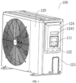
FIG. 1 is a structural view of an air conditioner according to embodiment 1 of the present disclosure. -
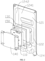
FIG. 2 is a local exploded view of an air conditioner according to embodiment 1 of the present disclosure. -
FIG. 3 is a local exploded view of an air conditioner according to embodiment 2 of the present disclosure. -
air conditioner 100;controller 110;operating surface 111;housing 120;accommodating cavity 121;operating hole 122;housing body 123;handle casing 124;end plate 1241; surroundingplate 1242;handle slot 1243;controller support member 130;controller limiting member 140;sealing ring 150;cover plate 160;controller mounting box 170. - Embodiments of the present disclosure are described in detail below, examples of which are shown in the accompanying drawings. The following embodiments described with reference to the accompanying drawings are illustrative. It should be understood that the embodiments described are intended to explain the present disclosure, but not to limit the present disclosure.
- The
air conditioner 100 of embodiments of the present disclosure is described below according toFIGS. 1-3 . Theair conditioner 100 includes a body and acontroller 110. - The body includes a
housing 120. Thehousing 120 includes a protruding portion protruding outwards, and the protruding portion defines anaccommodating cavity 121. At least a part of thecontroller 110 is located in theaccommodating cavity 121, that is, at least part of thecontroller 110 is located in theaccommodating cavity 121 formed by the protruding portion on thehousing 120 protruding outwards, and theaccommodating cavity 121 is located at a rear space of the protruding portion. - The protruding portion is provided with an
operating hole 122 communicated with theaccommodating cavity 121, anoperating surface 111 of thecontroller 110 is opposite to theoperating hole 122, and theoperating surface 111 is exposed through theoperating surface 111. Since theoperating surface 111 is exposed through theoperating surface 111, an operator may perform a touch operation on theoperating surface 111 of thecontroller 110. Alternatively, theoperating surface 111 of thecontroller 110 is arranged on an outer side surface of the protruding portion, and the operator may also perform the touch operation through theoperating surface 111 on the outer side surface of the protruding portion. - In the air conditioner provided according to embodiments of the present disclosure, the controller is arranged in an accommodating cavity formed by the protruding portion of the housing, and the accommodating cavity may be utilized without affecting the original appearance of the housing of the air conditioner, thus improving the space utilization inside the air conditioner.
- Therefore, the air conditioner provided by embodiments of the present disclosure has the advantage of high space utilization.
- In some embodiments, the
housing 120 includes ahousing body 123 and ahandle casing 124, thehandle casing 124 is detachably arranged on thehousing body 123, and thehandle casing 124 constitutes the protruding portion of thehousing 120. Further, thehandle casing 124 includes anend plate 1241 and a surroundingplate 1242 surrounding and connected to theend plate 1241. - Further, in some embodiments, the
controller 110 is detachably connected with thehandle casing 124, theend plate 1241 is provided with anoperating hole 122 communicated with theaccommodating cavity 121, theoperating surface 111 of thecontroller 110 is opposite to theoperating hole 122, and theoperating surface 111 is exposed through theoperating surface 111. The operator may perform a touch operation on theoperating surface 111 exposed throughoperation hole 122, and at this time, thecontroller 110 is built-in. Since thecontroller 110 is detachably connected to thehandle casing 124, thecontroller 110 may be removed from thehandle casing 124 and placed on an indoor wall or an outdoor wall, and in this time, thecontroller 110 is external. When removing thecontroller 110, thehandle casing 124 may be removed from thehousing body 123 first, and then thecontroller 110 connected to thehandle casing 124 may be removed, without disassembling the peripheral sheet metal of thehousing body 123 or thehousing 120, which is convenient and quick, convenient for after-sales maintenance, and makes the arrangement of thecontroller 110 more flexible. - Alternatively, in other embodiments, the
end plate 1241 is not provided with theoperating hole 122, and theoperating surface 111 of thecontroller 110 is arranged on theend plate 1241 and integrated with theend plate 1241. The outer side surface of theend plate 1241 is the outer side surface of the protruding portion. Further, thehandle casing 124 is integrated with theoperating surface 111 of thecontroller 110. Theoperating surface 111 is a touch-sensitive operating board, for example, thehandle casing 124 is made of plastic, and thecontroller 110 may be controlled by touching theoperating surface 111 arranged on theend plate 1241. - Several embodiments provided by the present embodiment are described in detail below according to
FIGS. 1-3 . - As shown in
FIGS. 1 and2 , in the present embodiment, anair conditioner 100 includes a body and acontroller 110. The body includes ahousing 120, and thehousing 120 includes ahousing body 123 and ahandle casing 124 detachably arranged on thehousing body 123. Thehandle casing 124 protrudes outwards with respect to thehousing body 123 to form a protruding portion. Thehandle casing 124 includes anend plate 1241 and a surroundingplate 1242, and theend plate 1241 and the surroundingplate 1242 define anaccommodating cavity 121 located on a rear side of theend plate 1241. A part of theend plate 1241 is recessed towards an interior of theaccommodating cavity 121 relative to a remaining part to form ahandle slot 1243, and thehandle slot 1243 is convenient for an operator to handle theair conditioner 100. - In other words, in the present embodiment, the
controller 110 is placed inside just by utilizing theaccommodating cavity 121 defined by thehandle casing 124 of theair conditioner 100, which does not change the original appearance of theair conditioner 100, and improves the space utilization. It should be noted that the present embodiment only takes thehandle casing 124 as an example. In other embodiments, thecontroller 110 may also be placed in anaccommodating cavity 121 defined by the other protruding portions formed on thehousing 120 of theair conditioner 100, which may also improve the space utilization and not elaborated herein. - As shown in
FIG. 2 , anoperating hole 122 is defined in theend plate 1241 for exposing theoperating surface 111 of thecontroller 110. Thecontroller 110 is detachably connected to thehandle casing 124. In some specific embodiments, the operatingsurface 111 is located in theoperating hole 122, that is, the operatingsurface 111 is located between a front wall surface and a rear wall surface of theend plate 1241 in the front-and-rear direction, or theoperating surface 111 is flush with the front wall surface of theend plate 1241, which is not limited herein. - Specifically, the
controller 110 includes an operating panel, and theoperation surface 111 is arranged on the front side surface of the operating panel. The remaining part of thecontroller 120 is located at a rear side of the operating panel. At least a part of the operating panel is fitted in theoperating hole 122, and the remaining part of thecontroller 120 is located in theaccommodating cavity 121. The remaining part of thecontroller 120 abuts against the rear wall surface of theend plate 1241, and more specifically, the remaining part of thecontroller 120 abuts the part of theend plate 1241 located near theoperating hole 122, so that thecontroller 110 is limited in the forward direction. - When the
controller 110 in the present embodiment is mounted, the control panel of thecontroller 110 is mounted into theoperating hole 122 of thehandle casing 124 from rear to front. The above arrangement enables thecontroller 110 to be limited during the mounting from rear to front, so that thecontroller 110 will not move forward out of theoperation hole 122. - In some specific embodiments, the size of the remaining part of the
controller 110 is larger than the size of the operating panel part, thereby forming a step structure on thecontroller 110. - Further, in order to connect the
controller 110 with thehandle casing 124 mutually, theair conditioner 100 of the present embodiment also includes acontroller support member 130 and acontroller limiting member 140. - As shown in
FIG. 2 , thecontroller support member 130 is configured to support thecontroller 110. Thecontroller support member 130 is connected to the rear wall surface of theend plate 1241 and surrounds the remaining part of thecontroller 110 located in theaccommodating cavity 121. In addition, the remaining part of thecontroller 110 is fitted into thecontroller support member 130, so that thecontroller support member 130 limits and supports thecontroller 110 in up, down, left and right directions. In other words, thecontroller support member 130 is a hollow frame, and thecontroller 110 passes through a middle through hole of thecontroller support member 130 from rear to front, so that thecontroller support member 130 is sleeved on the remaining part of thecontroller 110. Thus, thecontroller 110 will not jump or move in the up, down, left and right directions. - After the
controller 110 is fitted with thecontroller support member 130, thecontroller limiting member 140 is mounted on the rear wall surface of theend plate 1241 from the rear, thecontroller limiting member 140 includes a part that abuts against thecontroller 110 in the front-and-rear direction, and the part abuts against the rear side of thecontroller 110 to limit thecontroller 110 in the backward direction. That is, thecontroller limiting member 140 is connected to the rear wall surface of theend plate 1241, and thecontroller limiting member 140 is configured to limit thecontroller 110 in the backward direction. Thus, through thecontroller support member 130 and thecontroller limiting member 140, thecontroller 110 and thehandle casing 124 are mutually fixed. It is understood that thecontroller limiting member 140 may also be connected to thecontroller support member 130. - In other embodiments, the
air conditioner 100 may also exclude thecontroller limiting member 140, so that thecontroller support member 130 is connected with a limiting part, and the limiting part abuts against thecontroller 110 in the front-and-rear direction, which may also realize limit on thecontroller 110 in the backward direction. That is, thecontroller support member 130 is configured to limit thecontroller 110 in the up, down, left and right directions and backward direction simultaneously. - In some specific embodiments, the
air conditioner 100 also includes asealing ring 150. The sealingring 150 is fitted in theoperating hole 122 and located between the part of the operating panel fitted in theoperating hole 122 and theend plate 1241. In other words, an outer peripheral surface of theseal ring 150 abuts against a peripheral surface of theoperating hole 122, an inner peripheral surface of theseal ring 150 abuts against a part of the operating panel located in theoperating hole 122, and theseal ring 150 is used for sealing between thecontroller 110 and theend plate 1241, to prevent water or dust from entering the interior of theair conditioner 100 through the gap between thecontroller 110 and theend plate 1241 to affect the operation of theair conditioner 100. - In a specific embodiment, the
air conditioner 100 further includes acover plate 160. Thecover plate 160 is connected to ahandle casing 124 in a rotatable manner between a covering position of covering theoperating surface 111 and an exposing position of exposing theoperating surface 111. Specifically, thecover plate 160 may be connected to theend plate 1241, and a connection position with theend plate 1241 may be located above theoperating hole 122. Whencontroller 110 does not need to be operated, thecover plate 160 may be rotated to the covering position of covering theoperating surface 111 to prevent water and dust. When an operation is needed, thecover plate 160 may be rotated to the exposing position of exposing theoperating surface 111, to facilitate the operation of theoperating surface 111. In addition, when thecontroller 110 needs to be removed and placed externally, thecover plate 160 may be moved to the covering position of covering theoperating surface 111, to prevent water or dust from entering the interior of the air conditioner through theoperating hole 122. - The
air conditioner 100 of the present embodiment is described below withFIG. 3 as an example. In the present embodiment, theair conditioner 100 includes a body and acontroller 110. The body includes ahousing 120, and thehousing 120 includes ahousing body 123 and ahandle casing 124 detachably arranged on thehousing body 123. Thehandle casing 124 protrudes outwards with respect to thehousing body 123 to form the protruding portion. Thehandle casing 124 includes anend plate 1241 and a surroundingplate 1242, and theend plate 1241 and the surroundingplate 1242 define anaccommodating cavity 121 located on the rear side of theend plate 1241. A part of theend plate 1241 is recessed towards the interior of theaccommodating cavity 121 relative to the remaining part of theend plate 1241 to form ahandle slot 1243, and thehandle slot 1243 is convenient for the operator to handle theair conditioner 100. - As shown in
FIG. 3 , theoperating hole 122 is defined in theend plate 1241. In the present embodiment, thecontroller 110 is detachably connected to thehandle casing 124. - Specifically, the
air conditioner 100 includes acontroller mounting box 170. Thecontroller mounting box 170 defines a mounting cavity, and a front side of the mounting cavity is open. Thecontroller 110 is mounted in the mounting cavity of thecontroller mounting box 170, the operatingsurface 111 is opposite to a front side opening of the mounting cavity so that the operatingsurface 111 is exposed, and at least a part of thecontroller mounting box 170 is located in theaccommodating cavity 121 and connected to theend plate 1241. It is understood that, in order to expose theoperating surface 111, the front side opening of the mounting cavity is opposite to theoperating hole 122. - When assembling the
air conditioner 100 in the present embodiment, thehandle casing 124 may be first mounted on thehousing body 123, thecontroller 110 may be mounted in the mounting cavity of thecontroller mounting box 170, thecontroller mounting box 170 mounted with thecontroller 110 passes through theoperating hole 122 from front to rear, and thecontroller mounting box 170 may be mounted into theaccommodating cavity 121. Alternatively, thecontroller mounting box 170 mounted with thecontroller 110 may be mounted on theend plate 1241 from rear to front, and then thehandle casing 124 may be connected to thehousing body 123. Adopting the first mounting method, when thecontroller 110 needs to be disassembled, thecontroller mounting box 170 may be directly removed from thehandle casing 124 without disassembling thehandle casing 124, which is more convenient and quicker. - In some specific embodiments, the
air conditioner 100 further includes acover plate 170, and thecover plate 160 is connected to thecontroller mounting box 170 in a rotatable manner between a covering position of covering theoperating surface 111 and an exposing position of exposing theoperating surface 111. Whencontroller 110 does not need to be operated, thecover plate 160 may be rotated to the covering position of covering theoperating surface 111 to prevent water and dust. When an operation is needed, thecover plate 160 may be rotated to the exposing position of exposing theoperating surface 111 to facilitate operation on theoperating surface 111. - In other embodiments, the
cover plate 160 may also be connected to thehandle casing 124 in a rotatable manner between the covering position of covering theoperating surface 111 and the exposing position of exposing theoperating surface 111. - In the description of the present disclosure, it should be understood that the orientation or position relationship indicated by the terms "center", "longitudinal", "transverse", "length", "width", "thickness", "up", "down", "front", "rear", "left", "right" , "vertical", "horizontal", "top", "bottom", "inner", "outer", "clockwise", "counterclockwise", "axial", "radial" and "circumferential" and the like, is based on the orientation or position relationship shown in the accompanying drawings, which is only for the convenience of describing the present disclosure and simplifying the description, and does not indicate or imply that the referred device or element must have a specific orientation, and be constructed and operated in a specific orientation, so it cannot be understood as a limitation of the present disclosure.
- In addition, the terms "first" and "second" are only used for purpose of description, and cannot be understood as indicating or implying relative importance or implicitly indicating the number of indicated technical features. Therefore, the feature defined as "first" or "second" may explicitly or implicitly include at least one such feature. In the description of the present disclosure, "a plurality of" means at least two, such as two, three, etc., unless otherwise specifically defined.
- In the present disclosure, unless otherwise expressly defined, terms such as "mount", "interconnect", "connect", "fix" shall be understood broadly, and may be, for example, fixed connections, detachable connections, or integral connections; may also be mechanical or electrical connections or intercommunication; may also be direct connections or indirect connections via intervening media; may also be inner communications or interactions of two elements, unless otherwise specifically defined. For those skilled in the art, the specific meaning of the above terms in the present disclosure can be understood according to the specific situations.
- In the present disclosure, unless otherwise expressly defined and specified, a structure in which a first feature is "on" or "below" a second feature may include an embodiment in which the first feature is in direct contact with the second feature, or may further include an embodiment in which the first feature and the second feature are in indirect contact through intermediate media. Furthermore, a first feature "on", "above", or "on top of" a second feature may include an embodiment in which the first feature is right or obliquely "on", "above", or "on top of" the second feature, or just means that the first feature is at a height higher than that of the second feature, while a first feature "below", "under", or "on bottom of" a second feature may include an embodiment in which the first feature is right or obliquely "below", "under", or "on bottom of" the second feature, or just means that the first feature is at a height lower than that of the second feature.
- In the description of the present disclosure, terms such as "an embodiment", "some embodiments", "an example", "a specific example" or "some examples" means that a particular feature, structure, material, or characteristic described in connection with the embodiment or example is included in at least one embodiment or example of the present disclosure. Thus, the appearances of these terms in various places throughout the present specification are not necessarily referring to the same embodiment or example of the present disclosure. Furthermore, the particular features, structures, materials, or characteristics may be combined in any suitable manner in one or more embodiments or examples. In addition, without contradiction, those skilled in the art may combine and unite different embodiments or examples or features of the different embodiments or examples described in the present specification.
- Although the embodiments of the present disclosure have been shown and described above, it can be understood that the above embodiments are illustrative and shall not be understood as limitation to the present disclosure, and changes, modifications, alternatives and variations can be made in the above embodiments within the scope of the present disclosure by those skilled in the art.
Claims (10)
- An air conditioner, comprising:a body, the body comprising a housing, the housing comprising a protruding portion protruding outwards, the protruding portion defining an accommodating cavity; anda controller, at least a part of the controller being located in the accommodating cavity, the protruding portion being provided with an operating hole communicated with the accommodating cavity, an operating surface of the controller being opposite to the operating hole so that the operating surface is exposed, or the operating surface of the controller being arranged on an outer side surface of the protruding portion.
- The air conditioner according to claim 1, wherein the housing comprises a housing body and a handle casing, the handle casing is detachably arranged on the housing body, the handle casing constitutes the protruding portion, and the handle casing comprises an end plate and a surrounding plate surrounding the end plate,
wherein the operating hole is defined in the end plate, and the controller is detachably connected with the handle casing, or, the operating surface is arranged on the end plate and integrated with the end plate. - The air conditioner according to claim 2, wherein a part of the end plate is recessed inwards relative to another part of the end plate to form a handle slot.
- The air conditioner according to claim 2, wherein the controller comprises an operating panel, the operating panel has the operation surface, at least a part of the operating panel is fitted in the operating hole, a remaining part of the controller is located at a rear side of the operating panel and is located in the accommodating cavity, and the remaining part of the controller abuts against a part of the end plate located near the operating hole, so that the controller is limited in a forward direction.
- The air conditioner according to claim 4, comprising a controller support member, wherein the controller support member is connected to a rear wall surface of the end plate and surrounds the remaining part of the controller, and the remaining part of the controller is fitted into the controller support member, so that the controller is limited and supposed in up, down, left and right directions.
- The air conditioner according to claim 5, wherein the controller support member is also connected with a limiting part abutting against the controller in the front-and-rear direction so that the controller limited in a backward direction,
or, the air conditioner further comprises a controller limiting member, the controller limiting member is connected with the controller support member or is connected with the rear wall surface of the end plate, and the controller limiting member comprises a part abutting against the controller in the front-and-rear direction, so that the controller is limited in the backward direction. - The air conditioner according to any one of claims 4-6, further comprising a sealing ring, wherein the sealing ring is fitted in the operating hole and located between the operating panel and the end plate.
- The air conditioner according to any one of claims 2-7, wherein the operating hole is defined in the end plate, the air conditioner comprises a controller mounting box, the controller mounting box defines a mounting cavity, a front side of the mounting cavity is open, the controller is mounted in the mounting cavity, the operating surface is opposite to a front side opening of the mounting cavity so that the operating surface is exposed, and at least a part of the controller mounting box is located in the accommodating cavity and connected to the end plate.
- The air conditioner according to claim 8, comprising a cover plate, wherein the cover plate is connected to the controller mounting box in a rotatable manner between a covering position of covering the operating surface and an exposing position of exposing the operating surface.
- The air conditioner according to any one of claims 2-8, comprising a cover plate, wherein the cover plate is connected to the handle casing in a rotatable manner between a covering position of covering the operating surface and an exposing position of exposing the operating surface.
Applications Claiming Priority (2)
| Application Number | Priority Date | Filing Date | Title |
|---|---|---|---|
| CN202121632827.6U CN216132086U (en) | 2021-07-16 | 2021-07-16 | Air conditioner |
| PCT/CN2022/082605 WO2023284331A1 (en) | 2021-07-16 | 2022-03-23 | Air conditioner |
Publications (3)
| Publication Number | Publication Date |
|---|---|
| EP4372292A1 true EP4372292A1 (en) | 2024-05-22 |
| EP4372292A4 EP4372292A4 (en) | 2024-10-30 |
| EP4372292B1 EP4372292B1 (en) | 2025-10-22 |
Family
ID=80767753
Family Applications (1)
| Application Number | Title | Priority Date | Filing Date |
|---|---|---|---|
| EP22840975.1A Active EP4372292B1 (en) | 2021-07-16 | 2022-03-23 | Air conditioner |
Country Status (4)
| Country | Link |
|---|---|
| US (1) | US20240393004A1 (en) |
| EP (1) | EP4372292B1 (en) |
| CN (1) | CN216132086U (en) |
| WO (1) | WO2023284331A1 (en) |
Families Citing this family (2)
| Publication number | Priority date | Publication date | Assignee | Title |
|---|---|---|---|---|
| CN115585548A (en) * | 2022-10-27 | 2023-01-10 | 深圳奥郎格环保有限公司 | air purification equipment |
| WO2025148938A1 (en) * | 2024-01-09 | 2025-07-17 | 广东美的暖通设备有限公司 | Panel structure, indoor unit, and hvac system |
Family Cites Families (13)
| Publication number | Priority date | Publication date | Assignee | Title |
|---|---|---|---|---|
| US6009717A (en) * | 1998-08-26 | 2000-01-04 | Carrier Corporation | Control box for a room air conditioner |
| JP4435823B2 (en) * | 2007-11-09 | 2010-03-24 | シャープ株式会社 | Opening cover device and air conditioner equipped with the same |
| CN203375540U (en) * | 2013-06-26 | 2014-01-01 | 广州华凌制冷设备有限公司 | Indoor unit of air conditioner |
| US20170176028A1 (en) * | 2015-12-18 | 2017-06-22 | Lg Electronics Inc. | Air conditioner |
| KR20180065725A (en) * | 2016-12-08 | 2018-06-18 | 엘지전자 주식회사 | Outdoor unit of air conditioning apparatus |
| EP3557149B1 (en) * | 2016-12-16 | 2021-01-20 | Mitsubishi Electric Corporation | Outdoor unit for air conditioner |
| CN108209226A (en) * | 2018-03-07 | 2018-06-29 | 佛山市顺德区美的洗涤电器制造有限公司 | The control panel mounting structure of household electrical appliance and combined kitchen electric appliance |
| EP3825622B1 (en) * | 2018-07-20 | 2024-11-06 | Mitsubishi Electric Corporation | Heat-pump hot-water supply outdoor unit |
| CN209042605U (en) * | 2018-10-12 | 2019-06-28 | 广东美的制冷设备有限公司 | Air-conditioner outdoor unit and air conditioner |
| CN209181118U (en) * | 2018-11-27 | 2019-07-30 | 广东美的制冷设备有限公司 | Air conditioner indoor unit and air conditioner |
| CN109539392B (en) * | 2018-12-29 | 2024-08-16 | 奥克斯空调股份有限公司 | Air conditioner |
| CN113448258A (en) * | 2020-03-26 | 2021-09-28 | 汉斯(上海)智能家居科技股份有限公司 | Intelligence house is with warm controlling means that leads to |
| CN212499789U (en) * | 2020-07-10 | 2021-02-09 | 河北顶控新能源科技有限公司 | Parking air conditioner structure |
-
2021
- 2021-07-16 CN CN202121632827.6U patent/CN216132086U/en active Active
-
2022
- 2022-03-23 EP EP22840975.1A patent/EP4372292B1/en active Active
- 2022-03-23 WO PCT/CN2022/082605 patent/WO2023284331A1/en not_active Ceased
- 2022-03-23 US US18/564,012 patent/US20240393004A1/en active Pending
Also Published As
| Publication number | Publication date |
|---|---|
| EP4372292B1 (en) | 2025-10-22 |
| WO2023284331A1 (en) | 2023-01-19 |
| CN216132086U (en) | 2022-03-25 |
| US20240393004A1 (en) | 2024-11-28 |
| EP4372292A4 (en) | 2024-10-30 |
Similar Documents
| Publication | Publication Date | Title |
|---|---|---|
| EP4372292B1 (en) | Air conditioner | |
| CN100498084C (en) | Indoor unit of air conditioner | |
| CN104422026A (en) | Air conditioner indoor unit | |
| CN209857235U (en) | window air conditioner | |
| CN103307716A (en) | Motor installation structure and installation method of air-conditioning indoor machine | |
| JP2017044411A (en) | Air conditioner | |
| CN108626783B (en) | Air guide plate assembly for air conditioner indoor unit, air conditioner indoor unit and air conditioner | |
| WO2019118347A1 (en) | Lightweight vehicle hvac structure | |
| CN108489051B (en) | Electric control box of air conditioner indoor unit, air conditioner indoor unit and air conditioner | |
| US20170254547A1 (en) | Indoor unit | |
| CN111936797B (en) | Ceiling embedded air conditioner | |
| CN207407442U (en) | Air conditioner indoor unit and air conditioner | |
| WO2022217893A1 (en) | Vertical air conditioner and machining system for air duct structure of vertical air conditioner | |
| CN220601627U (en) | An air duct machine | |
| JP2016130038A (en) | Register control knob | |
| CN205119375U (en) | Sensor device and air conditioner | |
| CN209763325U (en) | Window type air conditioner | |
| CN203478431U (en) | Air conditioner indoor unit | |
| CN216312838U (en) | Drive integrated device for vehicle and vehicle | |
| CN209763453U (en) | Panel assembly of window type air conditioner and window type air conditioner having same | |
| CN205279379U (en) | Cabinet air conditioner's procapsid module and cabinet air conditioner | |
| CN205119374U (en) | Sensor device and air conditioner | |
| CN116428666A (en) | Fragrance components, fragrance modules and air conditioners | |
| CN210688470U (en) | Air conditioner indoor unit | |
| CN223826451U (en) | Bearing seat mounting structure of air duct machine |
Legal Events
| Date | Code | Title | Description |
|---|---|---|---|
| STAA | Information on the status of an ep patent application or granted ep patent |
Free format text: STATUS: THE INTERNATIONAL PUBLICATION HAS BEEN MADE |
|
| PUAI | Public reference made under article 153(3) epc to a published international application that has entered the european phase |
Free format text: ORIGINAL CODE: 0009012 |
|
| STAA | Information on the status of an ep patent application or granted ep patent |
Free format text: STATUS: REQUEST FOR EXAMINATION WAS MADE |
|
| 17P | Request for examination filed |
Effective date: 20231124 |
|
| AK | Designated contracting states |
Kind code of ref document: A1 Designated state(s): AL AT BE BG CH CY CZ DE DK EE ES FI FR GB GR HR HU IE IS IT LI LT LU LV MC MK MT NL NO PL PT RO RS SE SI SK SM TR |
|
| DAV | Request for validation of the european patent (deleted) | ||
| DAX | Request for extension of the european patent (deleted) | ||
| A4 | Supplementary search report drawn up and despatched |
Effective date: 20240927 |
|
| RIC1 | Information provided on ipc code assigned before grant |
Ipc: F24F 13/20 20060101AFI20240923BHEP |
|
| GRAP | Despatch of communication of intention to grant a patent |
Free format text: ORIGINAL CODE: EPIDOSNIGR1 |
|
| STAA | Information on the status of an ep patent application or granted ep patent |
Free format text: STATUS: GRANT OF PATENT IS INTENDED |
|
| INTG | Intention to grant announced |
Effective date: 20250804 |
|
| GRAS | Grant fee paid |
Free format text: ORIGINAL CODE: EPIDOSNIGR3 |
|
| GRAA | (expected) grant |
Free format text: ORIGINAL CODE: 0009210 |
|
| STAA | Information on the status of an ep patent application or granted ep patent |
Free format text: STATUS: THE PATENT HAS BEEN GRANTED |
|
| AK | Designated contracting states |
Kind code of ref document: B1 Designated state(s): AL AT BE BG CH CY CZ DE DK EE ES FI FR GB GR HR HU IE IS IT LI LT LU LV MC MK MT NL NO PL PT RO RS SE SI SK SM TR |
|
| REG | Reference to a national code |
Ref country code: CH Ref legal event code: F10 Free format text: ST27 STATUS EVENT CODE: U-0-0-F10-F00 (AS PROVIDED BY THE NATIONAL OFFICE) Effective date: 20251022 Ref country code: GB Ref legal event code: FG4D |
|
| REG | Reference to a national code |
Ref country code: DE Ref legal event code: R096 Ref document number: 602022023645 Country of ref document: DE |
|
| REG | Reference to a national code |
Ref country code: IE Ref legal event code: FG4D |
|
| REG | Reference to a national code |
Ref country code: NL Ref legal event code: MP Effective date: 20251022 |
|
| PG25 | Lapsed in a contracting state [announced via postgrant information from national office to epo] |
Ref country code: NL Free format text: LAPSE BECAUSE OF FAILURE TO SUBMIT A TRANSLATION OF THE DESCRIPTION OR TO PAY THE FEE WITHIN THE PRESCRIBED TIME-LIMIT Effective date: 20251022 |
|
| PGFP | Annual fee paid to national office [announced via postgrant information from national office to epo] |
Ref country code: GB Payment date: 20260325 Year of fee payment: 5 |
|
| PG25 | Lapsed in a contracting state [announced via postgrant information from national office to epo] |
Ref country code: ES Free format text: LAPSE BECAUSE OF FAILURE TO SUBMIT A TRANSLATION OF THE DESCRIPTION OR TO PAY THE FEE WITHIN THE PRESCRIBED TIME-LIMIT Effective date: 20251022 |
|
| REG | Reference to a national code |
Ref country code: LT Ref legal event code: MG9D |
|
| PG25 | Lapsed in a contracting state [announced via postgrant information from national office to epo] |
Ref country code: NO Free format text: LAPSE BECAUSE OF FAILURE TO SUBMIT A TRANSLATION OF THE DESCRIPTION OR TO PAY THE FEE WITHIN THE PRESCRIBED TIME-LIMIT Effective date: 20260122 |
|
| PGFP | Annual fee paid to national office [announced via postgrant information from national office to epo] |
Ref country code: DE Payment date: 20260324 Year of fee payment: 5 |
|
| PG25 | Lapsed in a contracting state [announced via postgrant information from national office to epo] |
Ref country code: HR Free format text: LAPSE BECAUSE OF FAILURE TO SUBMIT A TRANSLATION OF THE DESCRIPTION OR TO PAY THE FEE WITHIN THE PRESCRIBED TIME-LIMIT Effective date: 20251022 Ref country code: AT Free format text: LAPSE BECAUSE OF FAILURE TO SUBMIT A TRANSLATION OF THE DESCRIPTION OR TO PAY THE FEE WITHIN THE PRESCRIBED TIME-LIMIT Effective date: 20251022 Ref country code: FI Free format text: LAPSE BECAUSE OF FAILURE TO SUBMIT A TRANSLATION OF THE DESCRIPTION OR TO PAY THE FEE WITHIN THE PRESCRIBED TIME-LIMIT Effective date: 20251022 |
|
| PGFP | Annual fee paid to national office [announced via postgrant information from national office to epo] |
Ref country code: AT Payment date: 20260301 Year of fee payment: 5 |
|
| REG | Reference to a national code |
Ref country code: AT Ref legal event code: MK05 Ref document number: 1849447 Country of ref document: AT Kind code of ref document: T Effective date: 20251022 |
|
| PG25 | Lapsed in a contracting state [announced via postgrant information from national office to epo] |
Ref country code: RS Free format text: LAPSE BECAUSE OF FAILURE TO SUBMIT A TRANSLATION OF THE DESCRIPTION OR TO PAY THE FEE WITHIN THE PRESCRIBED TIME-LIMIT Effective date: 20260122 |
|
| PG25 | Lapsed in a contracting state [announced via postgrant information from national office to epo] |
Ref country code: IS Free format text: LAPSE BECAUSE OF FAILURE TO SUBMIT A TRANSLATION OF THE DESCRIPTION OR TO PAY THE FEE WITHIN THE PRESCRIBED TIME-LIMIT Effective date: 20260222 |
|
| PG25 | Lapsed in a contracting state [announced via postgrant information from national office to epo] |
Ref country code: PT Free format text: LAPSE BECAUSE OF FAILURE TO SUBMIT A TRANSLATION OF THE DESCRIPTION OR TO PAY THE FEE WITHIN THE PRESCRIBED TIME-LIMIT Effective date: 20260223 |
|
| PG25 | Lapsed in a contracting state [announced via postgrant information from national office to epo] |
Ref country code: PL Free format text: LAPSE BECAUSE OF FAILURE TO SUBMIT A TRANSLATION OF THE DESCRIPTION OR TO PAY THE FEE WITHIN THE PRESCRIBED TIME-LIMIT Effective date: 20251022 |
|
| PG25 | Lapsed in a contracting state [announced via postgrant information from national office to epo] |
Ref country code: LV Free format text: LAPSE BECAUSE OF FAILURE TO SUBMIT A TRANSLATION OF THE DESCRIPTION OR TO PAY THE FEE WITHIN THE PRESCRIBED TIME-LIMIT Effective date: 20251022 |
|
| PG25 | Lapsed in a contracting state [announced via postgrant information from national office to epo] |
Ref country code: BG Free format text: LAPSE BECAUSE OF FAILURE TO SUBMIT A TRANSLATION OF THE DESCRIPTION OR TO PAY THE FEE WITHIN THE PRESCRIBED TIME-LIMIT Effective date: 20251022 |