EP4371877A2 - Vertical take-off and landing aircraft - Google Patents
Vertical take-off and landing aircraft Download PDFInfo
- Publication number
- EP4371877A2 EP4371877A2 EP24165225.4A EP24165225A EP4371877A2 EP 4371877 A2 EP4371877 A2 EP 4371877A2 EP 24165225 A EP24165225 A EP 24165225A EP 4371877 A2 EP4371877 A2 EP 4371877A2
- Authority
- EP
- European Patent Office
- Prior art keywords
- aircraft
- proprotor
- rotor
- proprotors
- rotors
- Prior art date
- Legal status (The legal status is an assumption and is not a legal conclusion. Google has not performed a legal analysis and makes no representation as to the accuracy of the status listed.)
- Granted
Links
Images




Classifications
-
- B—PERFORMING OPERATIONS; TRANSPORTING
- B64—AIRCRAFT; AVIATION; COSMONAUTICS
- B64C—AEROPLANES; HELICOPTERS
- B64C29/00—Aircraft capable of landing or taking-off vertically, e.g. vertical take-off and landing [VTOL] aircraft
- B64C29/0008—Aircraft capable of landing or taking-off vertically, e.g. vertical take-off and landing [VTOL] aircraft having its flight directional axis horizontal when grounded
- B64C29/0016—Aircraft capable of landing or taking-off vertically, e.g. vertical take-off and landing [VTOL] aircraft having its flight directional axis horizontal when grounded the lift during taking-off being created by free or ducted propellers or by blowers
- B64C29/0033—Aircraft capable of landing or taking-off vertically, e.g. vertical take-off and landing [VTOL] aircraft having its flight directional axis horizontal when grounded the lift during taking-off being created by free or ducted propellers or by blowers the propellers being tiltable relative to the fuselage
-
- B—PERFORMING OPERATIONS; TRANSPORTING
- B64—AIRCRAFT; AVIATION; COSMONAUTICS
- B64C—AEROPLANES; HELICOPTERS
- B64C29/00—Aircraft capable of landing or taking-off vertically, e.g. vertical take-off and landing [VTOL] aircraft
- B64C29/0008—Aircraft capable of landing or taking-off vertically, e.g. vertical take-off and landing [VTOL] aircraft having its flight directional axis horizontal when grounded
-
- B—PERFORMING OPERATIONS; TRANSPORTING
- B64—AIRCRAFT; AVIATION; COSMONAUTICS
- B64C—AEROPLANES; HELICOPTERS
- B64C27/00—Rotorcraft; Rotors peculiar thereto
- B64C27/22—Compound rotorcraft, i.e. aircraft using in flight the features of both aeroplane and rotorcraft
- B64C27/26—Compound rotorcraft, i.e. aircraft using in flight the features of both aeroplane and rotorcraft characterised by provision of fixed wings
-
- B—PERFORMING OPERATIONS; TRANSPORTING
- B64—AIRCRAFT; AVIATION; COSMONAUTICS
- B64C—AEROPLANES; HELICOPTERS
- B64C27/00—Rotorcraft; Rotors peculiar thereto
- B64C27/22—Compound rotorcraft, i.e. aircraft using in flight the features of both aeroplane and rotorcraft
- B64C27/28—Compound rotorcraft, i.e. aircraft using in flight the features of both aeroplane and rotorcraft with forward-propulsion propellers pivotable to act as lifting rotors
-
- B—PERFORMING OPERATIONS; TRANSPORTING
- B64—AIRCRAFT; AVIATION; COSMONAUTICS
- B64C—AEROPLANES; HELICOPTERS
- B64C27/00—Rotorcraft; Rotors peculiar thereto
- B64C27/52—Tilting of rotor bodily relative to fuselage
-
- B—PERFORMING OPERATIONS; TRANSPORTING
- B64—AIRCRAFT; AVIATION; COSMONAUTICS
- B64C—AEROPLANES; HELICOPTERS
- B64C27/00—Rotorcraft; Rotors peculiar thereto
- B64C27/54—Mechanisms for controlling blade adjustment or movement relative to rotor head, e.g. lag-lead movement
-
- B—PERFORMING OPERATIONS; TRANSPORTING
- B64—AIRCRAFT; AVIATION; COSMONAUTICS
- B64C—AEROPLANES; HELICOPTERS
- B64C29/00—Aircraft capable of landing or taking-off vertically, e.g. vertical take-off and landing [VTOL] aircraft
-
- B—PERFORMING OPERATIONS; TRANSPORTING
- B64—AIRCRAFT; AVIATION; COSMONAUTICS
- B64C—AEROPLANES; HELICOPTERS
- B64C29/00—Aircraft capable of landing or taking-off vertically, e.g. vertical take-off and landing [VTOL] aircraft
- B64C29/0008—Aircraft capable of landing or taking-off vertically, e.g. vertical take-off and landing [VTOL] aircraft having its flight directional axis horizontal when grounded
- B64C29/0016—Aircraft capable of landing or taking-off vertically, e.g. vertical take-off and landing [VTOL] aircraft having its flight directional axis horizontal when grounded the lift during taking-off being created by free or ducted propellers or by blowers
- B64C29/0025—Aircraft capable of landing or taking-off vertically, e.g. vertical take-off and landing [VTOL] aircraft having its flight directional axis horizontal when grounded the lift during taking-off being created by free or ducted propellers or by blowers the propellers being fixed relative to the fuselage
-
- B—PERFORMING OPERATIONS; TRANSPORTING
- B64—AIRCRAFT; AVIATION; COSMONAUTICS
- B64C—AEROPLANES; HELICOPTERS
- B64C9/00—Adjustable control surfaces or members, e.g. rudders
-
- B—PERFORMING OPERATIONS; TRANSPORTING
- B64—AIRCRAFT; AVIATION; COSMONAUTICS
- B64D—EQUIPMENT FOR FITTING IN OR TO AIRCRAFT; FLIGHT SUITS; PARACHUTES; ARRANGEMENT OR MOUNTING OF POWER PLANTS OR PROPULSION TRANSMISSIONS IN AIRCRAFT
- B64D27/00—Arrangement or mounting of power plants in aircraft; Aircraft characterised by the type or position of power plants
- B64D27/02—Aircraft characterised by the type or position of power plants
- B64D27/30—Aircraft characterised by electric power plants
- B64D27/34—All-electric aircraft
-
- B—PERFORMING OPERATIONS; TRANSPORTING
- B64—AIRCRAFT; AVIATION; COSMONAUTICS
- B64D—EQUIPMENT FOR FITTING IN OR TO AIRCRAFT; FLIGHT SUITS; PARACHUTES; ARRANGEMENT OR MOUNTING OF POWER PLANTS OR PROPULSION TRANSMISSIONS IN AIRCRAFT
- B64D27/00—Arrangement or mounting of power plants in aircraft; Aircraft characterised by the type or position of power plants
- B64D27/02—Aircraft characterised by the type or position of power plants
- B64D27/30—Aircraft characterised by electric power plants
- B64D27/35—Arrangements for on-board electric energy production, distribution, recovery or storage
- B64D27/357—Arrangements for on-board electric energy production, distribution, recovery or storage using batteries
-
- B—PERFORMING OPERATIONS; TRANSPORTING
- B64—AIRCRAFT; AVIATION; COSMONAUTICS
- B64D—EQUIPMENT FOR FITTING IN OR TO AIRCRAFT; FLIGHT SUITS; PARACHUTES; ARRANGEMENT OR MOUNTING OF POWER PLANTS OR PROPULSION TRANSMISSIONS IN AIRCRAFT
- B64D31/00—Power plant control systems; Arrangement of power plant control systems in aircraft
- B64D31/16—Power plant control systems; Arrangement of power plant control systems in aircraft for electric power plants
Definitions
- This disclosure generally relates to vertical take-off and landing aircraft, and more specifically to fixed wing vertical take-off and landing aircraft.
- VTOL Vertical take-off and landing
- Helicopters are VTOL aircraft that generate lift entirely through their rotors.
- Some VTOL aircraft have wings and propulsion systems that enable the wings to provide the lift required during forward flight.
- Some winged VTOL aircraft use separate propulsion systems for vertical thrust for use during take-off and landing and forward thrust for use during cruising.
- Other winged VTOL aircraft use tiltable propulsion systems that tilt between vertical thrust and forward thrust positions.
- a vertical take-off and landing aircraft includes a fixed wing, a plurality of rotors for providing lift during vertical take-off and landing, and a plurality of proprotors that can tilt from lift configurations for providing lift during vertical take-off and landing to propulsion configurations for providing the forward air speed required for the aircraft to be supported by the fixed wing.
- a vertical take-off and landing aircraft includes a fuselage; at least one wing connected to the fuselage; a plurality of rotors connected to the at least one wing for providing lift for vertical take-off and landing of the aircraft; and a plurality of proprotors connected to the at least one wing and tiltable between lift configurations for providing lift for vertical take-off and landing of the aircraft and propulsion configurations for providing forward thrust to the aircraft.
- the plurality of rotors can be rearward of the at least one wing and the plurality of proprotors can be forward of the at least one wing.
- a plurality of booms can be mounted to the at least one wing, each boom mounting one rotor and one proprotor to the at least one wing.
- a first proprotor can be forward of a second proprotor that is adjacent to the first proprotor.
- a first proprotor can be mounted at a higher position on the aircraft than a second proprotor that is adjacent to the first proprotor.
- each rotor can have only two blades. In any of these embodiments, each rotor can be configured to fix the two blades in position during forward flight. In any of these embodiments, each proprotor can have greater than two blades.
- a first rotor of the plurality of rotors can be canted relative to a second rotor of the plurality of rotors such that a rotational axis of the first rotor is non-parallel with a rotational axis of the second rotor.
- a cant angle of any rotor or proprotor is such that a respective burst disc cannot intersect with passengers or a pilot.
- a cant angle of any rotor or proprotor is such that a respective burst disc cannot intersect with any flight-critical component.
- a first proprotor of the plurality of proprotors can be canted relative to a second proprotor of the plurality of proprotors such that a rotational axis of the first proprotor is non-parallel with a rotational axis of the second proprotor.
- the aircraft further includes a control system configured to actively alter a tilt of at least one proprotor to generate yawing moments during hover.
- attack angles of blades of the proprotors can be collectively adjustable during flight.
- propulsion can be provided entirely by the proprotors.
- a range of tilt of the proprotors can be greater than ninety degrees.
- the at least one wing can provide the lift required during cruising.
- the at least one wing can be a high wing mounted to an upper side of the fuselage.
- the at least one wing has control surfaces.
- all of the rotors and proprotors are mounted to the at least one wing.
- the aircraft is electrically powered.
- the aircraft is manned.
- VTOL aircraft described herein include at least one fixed wing, a plurality of rotors that are fixed for providing lift during take-off, landing, and hover, and a plurality of proprotors that are tiltable from lift configurations for providing lift to propulsion configurations for providing the forward thrust needed for the at least one fixed wing to provide the lift to the aircraft.
- the VTOL aircraft By configuring the VTOL aircraft so that a portion of the propulsion system is dedicated to lift and a portion of the propulsion system is used during both lift and forward flight, the aircraft can be lighter and have lower drag than VTOL aircraft that have separate lift and propulsion systems and VTOL aircraft that use all propulsion for both lift and forward flight.
- Winged VTOL aircraft that have separate propulsion systems for vertical propulsion and forward propulsion essentially waste the forward propulsion system during vertical take-off and landing and hover.
- aircraft according to the principles described herein utilize the forward propulsion system during vertical take-off and landing, which can results in a relatively light propulsion system overall.
- Winged VTOL aircraft that tilt all of their rotors have limited places to position the rotors (rotors must be positioned forward and rearward of the center of gravity but their positioning is limited by the other rotors and the wings), which often results in relatively fewer, and therefore larger, rotors.
- propulsion systems according to the principles described herein can be have relatively smaller, lighter weight, and lower drag rotors.
- aircraft according to various embodiments described here have an ideal balance between a dedicated lift propulsion system and a tiltable propulsion sy stem.
- the proprotors are mounted to wing(s), forward of the leading edge, and the rotors are mounted to the wing(s), rearward of the trailing edge.
- the proprotors and rotors can be mounted to the wings via booms.
- each boom supports a proprotor at its front end and a rotor at its rear end.
- the proprotors are staggered in the forward and rearward direction to prevent broken blades of one proprotor from hitting the blades of the adjacent proprotor.
- the rotors and/or proprotors are positioned and canted so that their blades do not intersect one another and to enhance yaw control authority.
- the rotors and/or proprotors are positioned and canted so that the planes of rotation of their blades do not intersect passengers and/or critical system components to minimize the potential damage resulting from a blade breaking during flight.
- the wings are located high on the fuselage for easy passenger ingress and egress.
- the aircraft can be configured so that the bottom of the booms supporting the rotor and proprotors are above the head of an average sized person, which also contributed to ease of ingress and egress.
- proprotor refers to a variable pitch propeller that can provide thrust for vertical lift and for forward propulsion by varying the pitch of the propeller.
- FIGS. 1 and 2 illustrate a VTOL aircraft 100 in a cruise configuration and a vertical take-off and landing configuration, respectively, according to various embodiments.
- the aircraft 100 includes a fuselage 102, wings 104 mounted to the fuselage 102, and one or more rear stabilizers 106 mounted to the rear of the fuselage 102.
- a plurality of rotors 112 are mounted to the wings 104 and are configured to provide lift for vertical take-off and landing.
- a plurality of proprotors 114 are mounted to the wings 104 and are tiltable between lift configurations in which they provide a portion of the lift required for vertical take-off and landing and hovering, as shown in FIG. 2 , and propulsion configurations in which they provide forward thrust to the aircraft 100 for horizontal flight, as shown in FIG.
- a proprotor lift configuration refers to any proprotor orientation in which the proprotor thrust is providing primarily lift to the aircraft and proprotor propulsion configuration refers to any proprotor orientation in which the proprotor thrust is providing primarily forward thrust to the aircraft.
- the rotors 112 are configured for providing lift only, with all propulsion being provided be the proprotors. Accordingly, the rotors 112 may be in fixed positions. During take-off and landing, the proprotors 114 are tilted to lift configurations in which their thrust is directed downwardly for providing additional lift.
- the proprotors 114 tilt from their lift configurations to their propulsion configurations.
- the pitch of the proprotors 114 is varied from a pitch in which the proprotor thrust is directed downward to provide lift during vertical take-off and landing and during hover to a pitch in which the proprotor thrust is directed rearward to provide forward thrust to the aircraft 100.
- the proprotors tilt about axes 118 that are perpendicular to the forward direction of the aircraft 100.
- lift may be provided entirely by the wings 104, and the rotors 112 may be shut-off.
- the blades 120 of the rotors 112 may be locked in low drags positions for aircraft cruising.
- the rotors 112 each have two blades 120 that are locked for cruising in minimum drag positions in which one blade is directly in front of the other blade as illustrated in FIG. 1 .
- the rotors 112 have more than two blades.
- the proprotors 114 include more blades 116 than the rotors 112.
- the rotors 112 may each include two blades and the proprotors 114 may each include five blades.
- the proprotors 114 can have from 2 to 5 blades.
- the aircraft includes only one wing 104 on each side of the fuselage 102 (or a single wing that extends across the entire aircraft) and at least a portion of the rotors 112 are located rearward of the wings 104 and at least a portion of the proprotors 114 are located forward of the wings 104. In some embodiments, all of the rotors 112 are located rearward of the wings 104 and all of the proprotors are located forward of the wings 104. According to some embodiments, all rotors 112 and proprotors 114 are mounted to the wings-i.e., no rotors or proprotors are mounted to the fuselage.
- the rotors 112 are all located rearwardly of the wings 104 and the proprotors 114 are all located forward of the wings 104. According to some embodiments, all rotors 112 and proprotors 114 are positioned inwardly of the wing tips 109.
- the rotors 112 and proprotors 114 are mounted to the wings 104 by booms 122.
- the booms 122 may be mounted beneath the wings 104, on top of the wings, and/or may be integrated into the wing profile.
- one rotor 112 and one proprotor 114 are mounted to each boom 122.
- the rotor 112 may be mounted at a rear end of the boom 122 and a proprotor 114 may be mounted at a front end of the boom 122.
- the rotor 112 is mounted in a fixed position on the boom 122.
- the proprotor 114 is mounted to a front end of the boom 122 via a hinge 124.
- the proprotor 114 may be mounted to the boom 122 such that the proprotor 114 is aligned with the body of the boom 122 when in its propulsion configuration, forming a continuous extension of the front end of the boom 122 that minimizes drag for forward flight.
- the aircraft 100 may include only one wing on each side of the aircraft 100 or a single wing that extends across the aircraft.
- the at least one wing 104 is a high wing mounted to an upper side of the fuselage 102.
- the wings include control surfaces, such as flaps and/or ailerons.
- the wings can have curved wing tips 109 for reduced drag during forward flight.
- the rear stabilizers 106 include control surfaces, such as one or more rudders, one or more elevators, and/or one or more combined rudder-elevators.
- the wing(s) may have any suitable design.
- the wings have a tapering leading edge 123, as shown for example, in the embodiment of FIG. 1 .
- the wings have a tapering trailing edge 125 as shown in the embodiment of FIG. 3 .
- the wings have a substantially straight leading edge 127 in the central section of the wings 104.
- Aircraft 100 may include at least one door 110 for passenger entry and exit.
- the door 110 is located beneath and forward of the wings 104.
- the rotors 112 and proprotors 114 are positioned and configured to minimize the damage that may occur due to blade failure (commonly referred to as rotor burst).
- FIG. 3-6 show the relative locations and orientations of the rotor and proprotor blades during use, according to some embodiments. The blade positions over full rotations are illustrated by discs.
- the proprotors each have two discs-one for the lift configuration and one for the propulsion configuration.
- the rotor and proprotor configurations on the left and right of the aircraft are mirror images, and therefore, the configurations of the rotors and proprotors of only one side of the aircraft are discussed below.
- the proprotors 114 may be staggered in the forward-rearward direction such that the plane of rotation of the proprotors in their propulsion configurations are non-coplanar.
- the innermost proprotor 114a is forward of the other proprotors.
- the innermost proprotors 114a are forward of the passenger compartment or the forward-most location of passengers in the passenger compartment to ensure that a broken blade cannot enter the passenger compartment and injure a passenger.
- at least two proprotors on the same side of the aircraft are aligned such that their blade rotation planes are coplanar.
- the rotors 112 are in staggered forward-rearward positions. In some embodiments, the innermost rotors 112a are positioned rearward of the other rotors. In some embodiments, at least a portion of the rotors 112 are aligned in the forward rearward direction.
- At least one of the rotors 112 and/or proprotors 114 is canted relative to at least one other rotor 112 and/or proprotor 114.
- canting refers to a relative orientation of the rotational axis of the rotor/proprotor about a line that is parallel to the forward-rearward direction, analogous to the roll degree of freedom of the aircraft.
- Canting of the rotors and/or proprotors can help minimize damage from rotor burst by orienting the rotational plane of the rotor/proprotor discs (the blades plus the rotor portion onto which the blades are mounted) so as to not intersect critical portions of the aircraft (such areas of the fuselage in which people may be positioned, critical flight control systems, batteries, adjacent rotors/proprotors, etc.) or other rotor discs and may provide enhanced yaw control during flight.
- a cant angle of any rotor or proprotor is such that a respective burst disc will not intersect with passengers or a pilot.
- a cant angle of any rotor or proprotor is such that a respective burst disc will not intersect with any flight-critical component.
- a critical component is any component whose failure would contribute to or cause a failure condition that would prevent the continued controlled flight and landing of the aircraft.
- the front view of FIG. 5 best illustrates the canting of the rotors and proprotors, according to some embodiments.
- a rotation axis 130a for the innermost proprotor 114a in its lift configuration is provided to illustrate the cant angle of the proprotor 114a.
- the canting of the proprotors 114 results in the rotation planes of their blades being angled relative to horizontal, as illustrated, for example, by disc 132a being non-horizontal.
- the illustrated cant angle 136a measured from vertical 138 is about 12 degrees, but can range from 0 to 30 degrees in either direction.
- the outermost proprotor 114c is canted the same amount and in the same direction as the innermost proprotor 114a and the middle proprotor 114b is canted by the same amount but in the opposite direction as the innermost and outermost proprotors 114a,c such that the rotational axis 130a of proprotor 114a is parallel to the rotational axis of the rotational axis 130c of proprotor 114c but non-parallel to the rotational axis 130b of proprotor 114b.
- this is merely one example of the relative canting of the proprotors and it will be understood to a person of skill in the art that any suitable combination of proprotor canting (inclusive of no canting) may be used according to the desired performance characteristics of the aircraft.
- the rotors 112 may also be canted in any suitable manner and combination.
- the rotors 112 are canted according to a corresponding proprotor.
- innermost rotor 112a is canted by the same amount and in the same direction as the innermost proprotor 114a as can be seen by comparing the innermost rotor blade disc 134a to the innermost proprotor blade disc 132a.
- rotor 112b and 112c are canted similarly to the corresponding proprotor 114b and 114c, respectively. Note that in FIG.
- the innermost rotor blade disc 134a is not depicted as a straight line due to the innermost rotor 112a being oriented with a rearward tilt as discussed further below. Any suitable combination of canting and/or non-canting of the rotors relative to one another and relative to the proprotors can be used to achieve desired performance characteristics.
- FIG. 6 illustrates the relatively small rearward tilt of the outermost rotor 112c, according to the illustrated embodiment.
- the rotational axis 140c of the rotor 112c is tilted rearward from vertical 142 by an angle 144c, which can range from 0 to 15 degrees in either direction.
- the slight rearward tilt of the rotor 112c can help with aircraft stability and yaw control.
- FIG. 6 also illustrates the range of tilt at least the outermost proprotor 114c, according to some embodiments.
- the outermost proprotor 114c can tilt from a straight-ahead position illustrated by the horizontal rotational axis 146c of the proprotor 114c in its propulsion configuration to a position just past (for example, less than 10 degrees past) vertical 148 as illustrated by rotational axis 150c of the proprotor 114c in its lift configuration, such that the proprotor 114c has a range of tilt 151c of about 100 degrees.
- each of the proprotors 114 has a range of greater than 90 degrees.
- FIGS. 7 and 8 illustrate the locations of the wings, rotors, and proprotors relative to a person on the ground, according to some embodiments.
- the aircraft 100 may be configured so that the bottom 152a of the innermost proprotor 114a is located above the head of a person standing on the ground next to the fuselage (for example, preparing to enter the aircraft) when the aircraft 100 is supported by its landing gear 154 on the ground. Locating the wings in high positions on the upper portion of the fuselage 102 can ensure maximum head room for people entering and exiting the aircraft.
- FIGS. 7 and 8 also show a person sitting in the cabin of the fuselage to illustrate the relative size of the aircraft, according to some embodiments.
- the rotors 112 and proprotors 114 are all electrically powered. Batteries for powering the rotors 112 and proprotors 114 can be located in any suitable locations of the aircraft, including in the fuselage and/or the wings. The number and power of the rotors and proprotors can be selected according to the desired performance parameters (e.g., target payload, airspeed, and altitude). According to some embodiments, the maximum power rating of one or more of the rotors and proprotors is 500 kilowatts or less, preferably 200 kilowatts or less, more preferably 150 kilowatts or less.
- the maximum power rating of one or more of the rotors and proprotors is at least 10 kilowatts, preferably at least 20 kilowatts, more preferably, at least 50 kilowatts.
- the number of proprotors can range from as little as 2 (one on each side of the aircraft) to a maximum of 24 (12 on each side of the aircraft).
- the number of proprotors is in the range of 4 to 8.
- the number of rotors can range from 2 to 24, and is preferably in the range of 4 to 8.
- the aircraft can have an equal number of rotors and proprotors, a greater number of proprotors, or a greater number of rotors.
- Aircraft according to the principles discussed above can be configured to carry up to 10 people, preferably up to 6 people, and more preferably up to 4 people.
- the aircraft is configured to be piloted and includes piloting controls.
- the aircraft is configured to operate autonomously without any onboard pilot.
- the aircraft is configured to carry up to 6 people (for example, a pilot and up to 5 passengers) up to 75 miles at a cruising speed of up to 150 miles per hour at an altitude of up to 3,000 feet above ground.
- the aircraft is configured for 5 people, such as one pilot and four passengers.
- the maximum range on a single battery charge is 25 miles, 50 miles, 75 miles, 100 miles, or 200 miles.
- the rotors 112 and/or proprotors 114 are configured to have relatively low tip speed to decrease the amount of noise generated by the aircraft.
- the tip speed of the rotor blades is about 0.4 Mach in hover.
- the diameter of the rotor and/or proprotor blades is the range of 1 to 5 meters, preferably in the range of 1.5 to 2 meters.
- the wingspan is in the range of 10 to 20 meters, preferably in the range of 15 to 16 meters.
- the length of the aircraft is in the range of 3 to 20 meters, preferably in the range of 5 to 15 meters, more preferably in the range of 6 to 10 meters.
- the aircraft is operated during take-off and landing by positioning the proprotors in lift configurations and providing the required lift to the aircraft via the combined lift provided by the rotors and proprotors.
- the proprotors can be maintained in predetermined lift configurations that can be the same across all proprotors or different for different proprotors.
- the tilt of at least some of the proprotors can be actively adjusted during take-off and landing and/or hover to provide the required stability and/or maneuvering.
- the tilt of at least one proprotor is actively controlled by the flight controller during take-off, landing, and/or hover to generate yawing moments.
- each rotor and/or each proprotor can be individually controlled by the flight controller according to the various operational degrees of freedom.
- the only degree of freedom of the rotor is the rotational speed of the rotor.
- the angle of attack of the blades of the rotors can be collectively adjusted, providing an additional degree of freedom.
- the degrees of freedom of at least a portion of the proprotors includes the rotational speed of the proprotors, the collective attack angle of the blades, and the degree of tilt of the proprotors.
- any of these degrees of freedom can be actively controlled by the flight controller (either autonomously or in response to pilot commands) during take-off and landing in order to provide the appropriate stability and maneuvering.
- the proprotors begin tilting forward toward their propulsion configurations such that their thrust provides a combination of lift and thrust, with a decreasing proportion of lift as the proprotors are tilted further toward their propulsion configurations.
- the rotors can remain active during at least a portion of the period in which the proprotors are tilted forward to continue to provide rotor-based lift.
- the rotors can be deactivated. As discussed above, the rotor blades can be locked in a low-drag position.
- the tilt of at least some of the proprotors can be actively controlled to provide additional stability and/or maneuverability control.
- the tilt of at least some of the proprotors is actively controlled during take-off and landing and/or hover.
- the tilt of the proprotors is fixed (i.e., non-varying) during cruise.
- the tilt of the outermost proprotors can be actively and independently controlled during vertical take-off and landing and/or hover to provide yawing moments as needed.
Landscapes
- Engineering & Computer Science (AREA)
- Aviation & Aerospace Engineering (AREA)
- Mechanical Engineering (AREA)
- Chemical & Material Sciences (AREA)
- Combustion & Propulsion (AREA)
- Toys (AREA)
- Transmission Devices (AREA)
- Handcart (AREA)
- Braking Arrangements (AREA)
- Control Of Position, Course, Altitude, Or Attitude Of Moving Bodies (AREA)
- Radar Systems Or Details Thereof (AREA)
- Traffic Control Systems (AREA)
Abstract
Description
- This disclosure generally relates to vertical take-off and landing aircraft, and more specifically to fixed wing vertical take-off and landing aircraft.
- Vertical take-off and landing (VTOL) aircraft are aircraft that can take-off and land vertically and hover, providing the ability to carry travelers directly to their destination. Helicopters are VTOL aircraft that generate lift entirely through their rotors. Some VTOL aircraft have wings and propulsion systems that enable the wings to provide the lift required during forward flight. Some winged VTOL aircraft use separate propulsion systems for vertical thrust for use during take-off and landing and forward thrust for use during cruising. Other winged VTOL aircraft use tiltable propulsion systems that tilt between vertical thrust and forward thrust positions.
- According to various embodiments, a vertical take-off and landing aircraft includes a fixed wing, a plurality of rotors for providing lift during vertical take-off and landing, and a plurality of proprotors that can tilt from lift configurations for providing lift during vertical take-off and landing to propulsion configurations for providing the forward air speed required for the aircraft to be supported by the fixed wing. By configuring the VTOL aircraft so that a portion of the propulsion system is dedicated to lift and a portion of the propulsion system is used during both lift and forward flight, the aircraft can be lighter and have lower drag than VTOL aircraft that have separate lift and propulsion systems and VTOL aircraft that use all propulsion for both lift and forward flight.
- A vertical take-off and landing aircraft includes a fuselage; at least one wing connected to the fuselage; a plurality of rotors connected to the at least one wing for providing lift for vertical take-off and landing of the aircraft; and a plurality of proprotors connected to the at least one wing and tiltable between lift configurations for providing lift for vertical take-off and landing of the aircraft and propulsion configurations for providing forward thrust to the aircraft.
- In any of these embodiments, the plurality of rotors can be rearward of the at least one wing and the plurality of proprotors can be forward of the at least one wing. In any of these embodiments, a plurality of booms can be mounted to the at least one wing, each boom mounting one rotor and one proprotor to the at least one wing.
- In any of these embodiments, a first proprotor can be forward of a second proprotor that is adjacent to the first proprotor.
- In any of these embodiments, a first proprotor can be mounted at a higher position on the aircraft than a second proprotor that is adjacent to the first proprotor.
- In any of these embodiments, each rotor can have only two blades. In any of these embodiments, each rotor can be configured to fix the two blades in position during forward flight. In any of these embodiments, each proprotor can have greater than two blades.
- In any of these embodiments, a first rotor of the plurality of rotors can be canted relative to a second rotor of the plurality of rotors such that a rotational axis of the first rotor is non-parallel with a rotational axis of the second rotor. In any of these embodiments, a cant angle of any rotor or proprotor is such that a respective burst disc cannot intersect with passengers or a pilot. In any of these embodiments, a cant angle of any rotor or proprotor is such that a respective burst disc cannot intersect with any flight-critical component.
- In any of these embodiments, a first proprotor of the plurality of proprotors can be canted relative to a second proprotor of the plurality of proprotors such that a rotational axis of the first proprotor is non-parallel with a rotational axis of the second proprotor.
- In any of these embodiments, the aircraft further includes a control system configured to actively alter a tilt of at least one proprotor to generate yawing moments during hover.
- In any of these embodiments, attack angles of blades of the proprotors can be collectively adjustable during flight.
- In any of these embodiments, propulsion can be provided entirely by the proprotors.
- In any of these embodiments, a range of tilt of the proprotors can be greater than ninety degrees.
- In any of these embodiments, the at least one wing can provide the lift required during cruising.
- In any of these embodiments, the at least one wing can be a high wing mounted to an upper side of the fuselage.
- In any of these embodiments, the at least one wing has control surfaces.
- In any of these embodiments, all of the rotors and proprotors are mounted to the at least one wing.
- In any of these embodiments, the aircraft is electrically powered.
- In any of these embodiments, the aircraft is manned.
- The invention will now be described, by way of example only, with reference to the accompanying drawings, in which:
-
FIG. 1 shows a VTOL aircraft in a forward flight configuration, according to various embodiments; -
FIG. 2 shows a VTOL aircraft in a takeoff and landing configuration, according to various embodiments; -
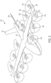
FIG. 3 is a perspective view of a VTOL aircraft illustrating the rotor and proprotor positions in the lift and forward flight configurations, according to various embodiments; -
FIG. 4 is a top view of the VTOL aircraft ofFIG. 3 ; -
FIG. 5 is a front view of the VTOL aircraft ofFIG. 3 ; -
FIG. 6 is a side view of the VTOL aircraft ofFIG. 3 ; and -
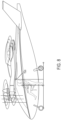
FIGS. 7 and8 are front and side views, respectively, of a VTOL aircraft illustrating the size of the aircraft relative to a standing person, according to various embodiments. - According to various embodiments, VTOL aircraft described herein include at least one fixed wing, a plurality of rotors that are fixed for providing lift during take-off, landing, and hover, and a plurality of proprotors that are tiltable from lift configurations for providing lift to propulsion configurations for providing the forward thrust needed for the at least one fixed wing to provide the lift to the aircraft. By configuring the VTOL aircraft so that a portion of the propulsion system is dedicated to lift and a portion of the propulsion system is used during both lift and forward flight, the aircraft can be lighter and have lower drag than VTOL aircraft that have separate lift and propulsion systems and VTOL aircraft that use all propulsion for both lift and forward flight. Winged VTOL aircraft that have separate propulsion systems for vertical propulsion and forward propulsion essentially waste the forward propulsion system during vertical take-off and landing and hover. In contrast, aircraft according to the principles described herein utilize the forward propulsion system during vertical take-off and landing, which can results in a relatively light propulsion system overall. Winged VTOL aircraft that tilt all of their rotors have limited places to position the rotors (rotors must be positioned forward and rearward of the center of gravity but their positioning is limited by the other rotors and the wings), which often results in relatively fewer, and therefore larger, rotors. In contrast, propulsion systems according to the principles described herein can be have relatively smaller, lighter weight, and lower drag rotors. Thus, aircraft according to various embodiments described here have an ideal balance between a dedicated lift propulsion system and a tiltable propulsion sy stem.
- According to various embodiments, the proprotors are mounted to wing(s), forward of the leading edge, and the rotors are mounted to the wing(s), rearward of the trailing edge. The proprotors and rotors can be mounted to the wings via booms. In some embodiments each boom supports a proprotor at its front end and a rotor at its rear end.
- According to various embodiments, the proprotors are staggered in the forward and rearward direction to prevent broken blades of one proprotor from hitting the blades of the adjacent proprotor. According to some embodiments, the rotors and/or proprotors are positioned and canted so that their blades do not intersect one another and to enhance yaw control authority. In some embodiments, the rotors and/or proprotors are positioned and canted so that the planes of rotation of their blades do not intersect passengers and/or critical system components to minimize the potential damage resulting from a blade breaking during flight.
- According to some embodiments, the wings are located high on the fuselage for easy passenger ingress and egress. The aircraft can be configured so that the bottom of the booms supporting the rotor and proprotors are above the head of an average sized person, which also contributed to ease of ingress and egress.
- In the following description of the disclosure and embodiments, reference is made to the accompanying drawings in which are shown, by way of illustration, specific embodiments that can be practiced. It is to be understood that other embodiments and examples can be practiced, and changes can be made, without departing from the scope of the disclosure.
- In addition, it is also to be understood that the singular forms "a," "an," and "the" used in the following description are intended to include the plural forms as well, unless the context clearly indicates otherwise. It is also to be understood that the term "and/or"," as used herein, refers to and encompasses any and all possible combinations of one or more of the associated listed items. It is further to be understood that the terms "includes, "including," "comprises," and/or "comprising," when used herein, specify the presence of stated features, integers, steps, operations, elements, components, and/or units, but do not preclude the presence or addition of one or more other features, integers, steps, operations, elements, components, units, and/or groups thereof.
- As used herein, the term "proprotor" refers to a variable pitch propeller that can provide thrust for vertical lift and for forward propulsion by varying the pitch of the propeller.
-
FIGS. 1 and2 illustrate aVTOL aircraft 100 in a cruise configuration and a vertical take-off and landing configuration, respectively, according to various embodiments. Theaircraft 100 includes afuselage 102,wings 104 mounted to thefuselage 102, and one or morerear stabilizers 106 mounted to the rear of thefuselage 102. A plurality ofrotors 112 are mounted to thewings 104 and are configured to provide lift for vertical take-off and landing. A plurality ofproprotors 114 are mounted to thewings 104 and are tiltable between lift configurations in which they provide a portion of the lift required for vertical take-off and landing and hovering, as shown inFIG. 2 , and propulsion configurations in which they provide forward thrust to theaircraft 100 for horizontal flight, as shown inFIG. 1 . As used herein, a proprotor lift configuration refers to any proprotor orientation in which the proprotor thrust is providing primarily lift to the aircraft and proprotor propulsion configuration refers to any proprotor orientation in which the proprotor thrust is providing primarily forward thrust to the aircraft. - According to various embodiments, the
rotors 112 are configured for providing lift only, with all propulsion being provided be the proprotors. Accordingly, therotors 112 may be in fixed positions. During take-off and landing, theproprotors 114 are tilted to lift configurations in which their thrust is directed downwardly for providing additional lift. - For forward flight, the
proprotors 114 tilt from their lift configurations to their propulsion configurations. In other words, the pitch of theproprotors 114 is varied from a pitch in which the proprotor thrust is directed downward to provide lift during vertical take-off and landing and during hover to a pitch in which the proprotor thrust is directed rearward to provide forward thrust to theaircraft 100. The proprotors tilt aboutaxes 118 that are perpendicular to the forward direction of theaircraft 100. When theaircraft 100 is in full forward flight, lift may be provided entirely by thewings 104, and therotors 112 may be shut-off. Theblades 120 of therotors 112 may be locked in low drags positions for aircraft cruising. In some embodiments, therotors 112 each have twoblades 120 that are locked for cruising in minimum drag positions in which one blade is directly in front of the other blade as illustrated inFIG. 1 . In some embodiments, therotors 112 have more than two blades. In some embodiments, theproprotors 114 includemore blades 116 than therotors 112. For example, as illustrated inFIG. 1 and2 , therotors 112 may each include two blades and theproprotors 114 may each include five blades. According to various embodiments, theproprotors 114 can have from 2 to 5 blades. - According to various embodiments, the aircraft includes only one
wing 104 on each side of the fuselage 102 (or a single wing that extends across the entire aircraft) and at least a portion of therotors 112 are located rearward of thewings 104 and at least a portion of theproprotors 114 are located forward of thewings 104. In some embodiments, all of therotors 112 are located rearward of thewings 104 and all of the proprotors are located forward of thewings 104. According to some embodiments, allrotors 112 andproprotors 114 are mounted to the wings-i.e., no rotors or proprotors are mounted to the fuselage. According to various embodiments, therotors 112 are all located rearwardly of thewings 104 and theproprotors 114 are all located forward of thewings 104. According to some embodiments, allrotors 112 andproprotors 114 are positioned inwardly of thewing tips 109. - According to various embodiments, the
rotors 112 andproprotors 114 are mounted to thewings 104 bybooms 122. Thebooms 122 may be mounted beneath thewings 104, on top of the wings, and/or may be integrated into the wing profile. According to various embodiments, onerotor 112 and one proprotor 114 are mounted to eachboom 122. Therotor 112 may be mounted at a rear end of theboom 122 and aproprotor 114 may be mounted at a front end of theboom 122. In some embodiments, therotor 112 is mounted in a fixed position on theboom 122. In some embodiments, theproprotor 114 is mounted to a front end of theboom 122 via ahinge 124. Theproprotor 114 may be mounted to theboom 122 such that theproprotor 114 is aligned with the body of theboom 122 when in its propulsion configuration, forming a continuous extension of the front end of theboom 122 that minimizes drag for forward flight. - According to various embodiments, the
aircraft 100 may include only one wing on each side of theaircraft 100 or a single wing that extends across the aircraft. According to some embodiments, the at least onewing 104 is a high wing mounted to an upper side of thefuselage 102. According to some embodiments, the wings include control surfaces, such as flaps and/or ailerons. According to some embodiments, the wings can havecurved wing tips 109 for reduced drag during forward flight. - According to some embodiments, the
rear stabilizers 106 include control surfaces, such as one or more rudders, one or more elevators, and/or one or more combined rudder-elevators. The wing(s) may have any suitable design. In some embodiments, the wings have atapering leading edge 123, as shown for example, in the embodiment ofFIG. 1 . In some embodiments, the wings have atapering trailing edge 125 as shown in the embodiment ofFIG. 3 . In the embodiment ofFIG. 3 , the wings have a substantially straightleading edge 127 in the central section of thewings 104. -
Aircraft 100 may include at least onedoor 110 for passenger entry and exit. In the illustrated embodiment, thedoor 110 is located beneath and forward of thewings 104. - According to various embodiments, the
rotors 112 andproprotors 114 are positioned and configured to minimize the damage that may occur due to blade failure (commonly referred to as rotor burst).FIG. 3-6 show the relative locations and orientations of the rotor and proprotor blades during use, according to some embodiments. The blade positions over full rotations are illustrated by discs. The proprotors each have two discs-one for the lift configuration and one for the propulsion configuration. The rotor and proprotor configurations on the left and right of the aircraft are mirror images, and therefore, the configurations of the rotors and proprotors of only one side of the aircraft are discussed below. - As illustrated in the top view of
FIG. 4 , theproprotors 114 may be staggered in the forward-rearward direction such that the plane of rotation of the proprotors in their propulsion configurations are non-coplanar. In the illustrated embodiments, theinnermost proprotor 114a is forward of the other proprotors. In some embodiments, the innermost proprotors 114a are forward of the passenger compartment or the forward-most location of passengers in the passenger compartment to ensure that a broken blade cannot enter the passenger compartment and injure a passenger. In some embodiments, at least two proprotors on the same side of the aircraft are aligned such that their blade rotation planes are coplanar. - According to some embodiments, the
rotors 112 are in staggered forward-rearward positions. In some embodiments, theinnermost rotors 112a are positioned rearward of the other rotors. In some embodiments, at least a portion of therotors 112 are aligned in the forward rearward direction. - According to some embodiments, at least one of the
rotors 112 and/orproprotors 114 is canted relative to at least oneother rotor 112 and/orproprotor 114. As used herein, canting refers to a relative orientation of the rotational axis of the rotor/proprotor about a line that is parallel to the forward-rearward direction, analogous to the roll degree of freedom of the aircraft. Canting of the rotors and/or proprotors can help minimize damage from rotor burst by orienting the rotational plane of the rotor/proprotor discs (the blades plus the rotor portion onto which the blades are mounted) so as to not intersect critical portions of the aircraft (such areas of the fuselage in which people may be positioned, critical flight control systems, batteries, adjacent rotors/proprotors, etc.) or other rotor discs and may provide enhanced yaw control during flight. In some embodiments, a cant angle of any rotor or proprotor is such that a respective burst disc will not intersect with passengers or a pilot. In some embodiments, a cant angle of any rotor or proprotor is such that a respective burst disc will not intersect with any flight-critical component. (As used herein, a critical component is any component whose failure would contribute to or cause a failure condition that would prevent the continued controlled flight and landing of the aircraft.) The front view ofFIG. 5 best illustrates the canting of the rotors and proprotors, according to some embodiments. Arotation axis 130a for the innermost proprotor 114a in its lift configuration is provided to illustrate the cant angle of the proprotor 114a. The canting of theproprotors 114 results in the rotation planes of their blades being angled relative to horizontal, as illustrated, for example, bydisc 132a being non-horizontal. The illustratedcant angle 136a measured from vertical 138 is about 12 degrees, but can range from 0 to 30 degrees in either direction. In the illustrated embodiment, theoutermost proprotor 114c is canted the same amount and in the same direction as theinnermost proprotor 114a and themiddle proprotor 114b is canted by the same amount but in the opposite direction as the innermost and outermost proprotors 114a,c such that therotational axis 130a of proprotor 114a is parallel to the rotational axis of therotational axis 130c ofproprotor 114c but non-parallel to therotational axis 130b ofproprotor 114b. However, this is merely one example of the relative canting of the proprotors and it will be understood to a person of skill in the art that any suitable combination of proprotor canting (inclusive of no canting) may be used according to the desired performance characteristics of the aircraft. - The
rotors 112 may also be canted in any suitable manner and combination. In some embodiments, therotors 112 are canted according to a corresponding proprotor. For example,innermost rotor 112a is canted by the same amount and in the same direction as the innermost proprotor 114a as can be seen by comparing the innermostrotor blade disc 134a to the innermostproprotor blade disc 132a. Similarly,rotor corresponding proprotor FIG. 5 , the innermostrotor blade disc 134a is not depicted as a straight line due to theinnermost rotor 112a being oriented with a rearward tilt as discussed further below. Any suitable combination of canting and/or non-canting of the rotors relative to one another and relative to the proprotors can be used to achieve desired performance characteristics. - The side view of
FIG. 6 illustrates the relatively small rearward tilt of theoutermost rotor 112c, according to the illustrated embodiment. Therotational axis 140c of therotor 112c is tilted rearward from vertical 142 by anangle 144c, which can range from 0 to 15 degrees in either direction. The slight rearward tilt of therotor 112c can help with aircraft stability and yaw control.FIG. 6 also illustrates the range of tilt at least theoutermost proprotor 114c, according to some embodiments. Theoutermost proprotor 114c can tilt from a straight-ahead position illustrated by the horizontalrotational axis 146c of the proprotor 114c in its propulsion configuration to a position just past (for example, less than 10 degrees past) vertical 148 as illustrated byrotational axis 150c of the proprotor 114c in its lift configuration, such that the proprotor 114c has a range oftilt 151c of about 100 degrees. According to various embodiments, each of theproprotors 114 has a range of greater than 90 degrees. -
FIGS. 7 and8 illustrate the locations of the wings, rotors, and proprotors relative to a person on the ground, according to some embodiments. Theaircraft 100 may be configured so that the bottom 152a of theinnermost proprotor 114a is located above the head of a person standing on the ground next to the fuselage (for example, preparing to enter the aircraft) when theaircraft 100 is supported by itslanding gear 154 on the ground. Locating the wings in high positions on the upper portion of thefuselage 102 can ensure maximum head room for people entering and exiting the aircraft.FIGS. 7 and8 also show a person sitting in the cabin of the fuselage to illustrate the relative size of the aircraft, according to some embodiments. - According to some embodiments, the
rotors 112 andproprotors 114 are all electrically powered. Batteries for powering therotors 112 andproprotors 114 can be located in any suitable locations of the aircraft, including in the fuselage and/or the wings. The number and power of the rotors and proprotors can be selected according to the desired performance parameters (e.g., target payload, airspeed, and altitude). According to some embodiments, the maximum power rating of one or more of the rotors and proprotors is 500 kilowatts or less, preferably 200 kilowatts or less, more preferably 150 kilowatts or less. According to some embodiments, the maximum power rating of one or more of the rotors and proprotors is at least 10 kilowatts, preferably at least 20 kilowatts, more preferably, at least 50 kilowatts. The number of proprotors can range from as little as 2 (one on each side of the aircraft) to a maximum of 24 (12 on each side of the aircraft). Preferably, the number of proprotors is in the range of 4 to 8. The number of rotors can range from 2 to 24, and is preferably in the range of 4 to 8. The aircraft can have an equal number of rotors and proprotors, a greater number of proprotors, or a greater number of rotors. - Aircraft according to the principles discussed above can be configured to carry up to 10 people, preferably up to 6 people, and more preferably up to 4 people. According to some embodiments, the aircraft is configured to be piloted and includes piloting controls. In some embodiments, the aircraft is configured to operate autonomously without any onboard pilot.
- According to some embodiments, the aircraft is configured to carry up to 6 people (for example, a pilot and up to 5 passengers) up to 75 miles at a cruising speed of up to 150 miles per hour at an altitude of up to 3,000 feet above ground. In some embodiments, the aircraft is configured for 5 people, such as one pilot and four passengers. According to various embodiments, the maximum range on a single battery charge is 25 miles, 50 miles, 75 miles, 100 miles, or 200 miles.
- According to various embodiments, the
rotors 112 and/orproprotors 114 are configured to have relatively low tip speed to decrease the amount of noise generated by the aircraft. In some embodiments, the tip speed of the rotor blades is about 0.4 Mach in hover. According to various embodiments, the diameter of the rotor and/or proprotor blades is the range of 1 to 5 meters, preferably in the range of 1.5 to 2 meters. - According to various embodiments, the wingspan is in the range of 10 to 20 meters, preferably in the range of 15 to 16 meters. According to various embodiments, the length of the aircraft is in the range of 3 to 20 meters, preferably in the range of 5 to 15 meters, more preferably in the range of 6 to 10 meters.
- According to various embodiments, the aircraft is operated during take-off and landing by positioning the proprotors in lift configurations and providing the required lift to the aircraft via the combined lift provided by the rotors and proprotors. According to various embodiments, during vertical take-off and landing and/or hover, the proprotors can be maintained in predetermined lift configurations that can be the same across all proprotors or different for different proprotors. According to various embodiments, the tilt of at least some of the proprotors can be actively adjusted during take-off and landing and/or hover to provide the required stability and/or maneuvering. According to some embodiments, the tilt of at least one proprotor is actively controlled by the flight controller during take-off, landing, and/or hover to generate yawing moments.
- According to various embodiments, each rotor and/or each proprotor can be individually controlled by the flight controller according to the various operational degrees of freedom. According to various embodiments, the only degree of freedom of the rotor is the rotational speed of the rotor. In some embodiments, the angle of attack of the blades of the rotors can be collectively adjusted, providing an additional degree of freedom. According to various embodiments, the degrees of freedom of at least a portion of the proprotors includes the rotational speed of the proprotors, the collective attack angle of the blades, and the degree of tilt of the proprotors. According to various embodiments, any of these degrees of freedom can be actively controlled by the flight controller (either autonomously or in response to pilot commands) during take-off and landing in order to provide the appropriate stability and maneuvering.
- Once the aircraft has achieved sufficient altitude to commence forward flight, the proprotors begin tilting forward toward their propulsion configurations such that their thrust provides a combination of lift and thrust, with a decreasing proportion of lift as the proprotors are tilted further toward their propulsion configurations. The rotors can remain active during at least a portion of the period in which the proprotors are tilted forward to continue to provide rotor-based lift. At any point after the forward airspeed is high enough that the wings provides sufficient lift to maintain the aircraft's altitude, the rotors can be deactivated. As discussed above, the rotor blades can be locked in a low-drag position.
- During cruising, the rotors remain deactivated. The control surfaces of the wings and/or rear stabilizers can be used for aircraft maneuvering and stability in a conventional manner. According to some embodiments, the tilt of at least some of the proprotors can be actively controlled to provide additional stability and/or maneuverability control. In some embodiments, the tilt of at least some of the proprotors is actively controlled during take-off and landing and/or hover. In some embodiments, the tilt of the proprotors is fixed (i.e., non-varying) during cruise. According to some embodiments, the tilt of the outermost proprotors can be actively and independently controlled during vertical take-off and landing and/or hover to provide yawing moments as needed.
- The foregoing description, for the purpose of explanation, has been described with reference to specific embodiments. However, the illustrative discussions above are not intended to be exhaustive or to limit the invention to the precise forms disclosed. Many modifications and variations are possible in view of the above teachings. The embodiments were chosen and described in order to best explain the principles of the techniques and their practical applications. Others skilled in the art are thereby enabled to best utilize the techniques and various embodiments with various modifications as are suited to the particular use contemplated.
- Although the disclosure and examples have been fully described with reference to the accompanying figures, it is to be noted that various changes and modifications will become apparent to those skilled in the art. Such changes and modifications are to be understood as being included within the scope of the disclosure and examples as defined by the claims. Finally, the entire disclosure of the patents and publications referred to in this application are hereby incorporated herein by reference.
- The following numbered embodiments form part of the present disclosure and may be claimed:
- 1. A vertical take-off and landing aircraft comprising:
- a fuselage;
- at least one wing connected to the fuselage;
- a plurality of rotors connected to the at least one wing for providing lift for vertical take-off and landing of the aircraft; and
- a plurality of proprotors connected to the at least one wing and tiltable between lift configurations for providing lift for vertical take-off and landing of the aircraft and propulsion configurations for providing forward thrust to the aircraft.
- 2. The aircraft of embodiment 1, wherein the plurality of rotors are rearward of the at least one wing and the plurality of proprotors are forward of the at least one wing.
- 3. The aircraft of embodiment 2, comprising a plurality of booms mounted to the at least one wing, each boom mounting one rotor and one proprotor to the at least one wing.
- 4. The aircraft of any one of embodiments 1-3, wherein a first proprotor is forward of a second proprotor that is adjacent to the first proprotor.
- 5. The aircraft of any one of embodiments 1-4, wherein a first proprotor is mounted at a higher position on the aircraft than a second proprotor that is adjacent to the first proprotor.
- 6. The aircraft of any one of embodiments 1-5, wherein each rotor has only two blades.
- 7. The aircraft of embodiment 6, wherein each rotor is configured to fix the two blades in position during forward flight.
- 8. The aircraft of embodiment 6 or embodiment 7, wherein each proprotor has greater than two blades.
- 9. The aircraft of any one of embodiments 1-8, wherein a first rotor of the plurality of rotors is canted relative to a second rotor of the plurality of rotors such that a rotational axis of the first rotor is non-parallel with a rotational axis of the second rotor.
- 10. The aircraft of embodiment 9, wherein a cant angle of any rotor or proprotor is such that a respective burst disc cannot intersect with passengers or a pilot.
- 11. The aircraft of embodiment 9 or embodiment 10, wherein a cant angle of any rotor or proprotor is such that a respective burst disc cannot intersect with any flight-critical component.
- 12. The aircraft of any one of embodiments 1-11, wherein a first proprotor of the plurality of proprotors is canted relative to a second proprotor of the plurality of proprotors such that a rotational axis of the first proprotor is non-parallel with a rotational axis of the second proprotor.
- 13. The aircraft of any one of embodiments 1-12, further comprising a control system configured to actively alter a tilt of at least one proprotor to generate yawing moments during hover.
- 14. The aircraft of any one of embodiments 1-13, wherein attack angles of blades of the proprotors are collectively adjustable during flight.
- 15. The aircraft of any one of embodiments 1-14, wherein propulsion is provided entirely by the proprotors.
- 16. The aircraft of any one of embodiments 1-15, wherein a range of tilt of the proprotors is greater than ninety degrees.
- 17. The aircraft of any one of embodiments 1-16, wherein the at least one wing provides the lift required during cruising.
- 18. The aircraft of any one of embodiments 1-17, wherein the at least one wing is a high wing mounted to an upper side of the fuselage.
- 19. The aircraft of any one of embodiments 1-18, wherein the at least one wing has control surfaces.
- 20. The aircraft of any one of embodiments 1-19, wherein all of the rotors and proprotors are mounted to the at least one wing.
- 21. The aircraft of any one of embodiments 1-20, wherein the aircraft is electrically powered.
- 22. The aircraft of any one of embodiments 1-21, wherein the aircraft is manned.
- 23. A vertical take-off and landing aircraft comprising:
- a fuselage;
- at least one wing connected to the fuselage;
- a plurality of rotors connected to the at least one wing for providing lift for vertical take-off and landing of the aircraft;
- a plurality of proprotors connected to the at least one wing and tiltable between lift configurations for providing lift for vertical take-off and landing of the aircraft and propulsion configurations for providing forward thrust to the aircraft;
- wherein each rotor of the plurality of rotors is fixed in position; and
- wherein:
- a first rotor (112a) of the plurality of rotors is canted relative to a second rotor (112b) of the plurality of rotors such that a rotational axis of the first rotor is non-parallel with a rotational axis of the second rotor, and/or
- a first proprotor of the plurality of proprotors is canted relative to a second proprotor of the plurality of proprotors such that a rotational axis of the first proprotor is non-parallel with a rotational axis of the second proprotor.
- 24. The aircraft of embodiment 23, wherein the plurality of rotors are rearward of the at least one wing and the plurality of proprotors are forward of the at least one wing.
- 25. The aircraft of embodiment 24, comprising a plurality of booms mounted to the at least one wing, each boom mounting one rotor and one proprotor to the at least one wing.
- 26. The aircraft of any one of embodiments 23-25, wherein a first proprotor (114a) is forward of a second proprotor (114b) that is adjacent to the first proprotor.
- 27. The aircraft of any one of embodiments 23-26, wherein a first proprotor (114a) is mounted at a higher position on the aircraft than a second proprotor (114b) that is adjacent to the first proprotor.
- 28. The aircraft of any one of embodiments 23-27, wherein each rotor has only two blades (120).
- 29. The aircraft of embodiment 28, wherein each rotor is configured to fix the two blades in position during forward flight.
- 30. The aircraft of embodiment 28, wherein each rotor is configured to fix the two blades for cruising in minimum drag positions during forward flight such that a first blade of the two blades is directly in front of a second blade of the two blades.
- 31. The aircraft of any one of embodiments 23-27, wherein each rotor has more than two blades.
- 32. The aircraft of embodiment 31, further configured to lock the rotor blades in a low-drag position during forward flight.
- 33. The aircraft of embodiment 28 or embodiment 29, wherein each proprotor has greater than two blades (116).
- 34. The aircraft of any one of preceding embodiments 23 to 33, wherein a cant angle (136a) of any rotor or proprotor is such that a respective burst disc cannot intersect with passengers or a pilot.
- 35. The aircraft of any one of preceding embodiments 23 to 34, wherein a cant angle (136a) of any rotor or proprotor is such that a respective burst disc cannot intersect with any flight-critical component.
- 36. The aircraft of any one of preceding embodiments 23 to 35, wherein a rotor cant angle between the rotational axis of the first rotor and a vertical axis of the aircraft is between 0 degrees and 30 degrees.
- 37. The aircraft of embodiment 36, wherein the rotor cant angle is about 12 degrees.
- 38. The aircraft of any one of preceding embodiments 23 to 37, wherein a proprotor cant angle between the rotational axis of the first proprotor and a vertical axis of the aircraft is between 0 degrees and 30 degrees.
- 39. The aircraft of embodiment 38, wherein the proprotor cant angle is about 12 degrees.
- 40. The aircraft of any one of preceding embodiments 23 to 39, further comprising a control system configured to actively alter a tilt of at least one proprotor (114) to generate yawing moments during take-off, landing and/or hover.
- 41. The aircraft of any one of preceding embodiments 23 to 40, wherein attack angles of blades (116) of the proprotors are collectively adjustable during flight.
- 42. The aircraft of any one of preceding embodiments 23 to 41, wherein propulsion is provided entirely by the proprotors.
- 43. The aircraft of any one of preceding embodiments 23 to 42, wherein a range of tilt of the proprotors is greater than ninety degrees.
- 44. The aircraft of any one of preceding embodiments 23 to 43, wherein the plurality of proprotors comprises an outermost proprotor, wherein a range of tilt of the outermost proprotor is about 100 degrees.
- 45. The aircraft of any one of preceding embodiments 23 to 44, wherein the at least one wing provides the lift required during cruising.
- 46. The aircraft of any one of preceding embodiments 23 to 45, wherein the at least one wing is a high wing mounted to an upper side of the fuselage.
- 47. The aircraft of any one of preceding embodiments 23 to 46, wherein the at least one wing has control surfaces.
- 48. The aircraft of any one of preceding embodiments 23 to 47, wherein all of the rotors and proprotors are mounted to the at least one wing.
- 49. The aircraft of any one of preceding embodiments 23 to 48, wherein the aircraft is electrically powered.
- 50. The aircraft of any one of preceding embodiments 23 to 49, wherein the aircraft is manned.
- 51. The aircraft of any one of preceding embodiments 23 to 50, wherein at least two proprotors of the plurality of proprotors are on a first side of the aircraft, wherein the at least two proprotors are aligned such that their blade rotation planes are coplanar.
- 52. The aircraft of any one of preceding embodiments 23 to 51, wherein the plurality of rotors comprises an outermost rotor, and wherein a rotational axis of the outermost rotor is tilted rearward or forward relative to a vertical axis of the aircraft.
- 53. The aircraft of any one of preceding embodiments 23 to 52, wherein the plurality of rotors comprises an innermost rotor, and wherein a rotational axis of the innermost rotor is tilted rearward or forward relative to a vertical axis of the aircraft.
Claims (17)
- A vertical take-off and landing aircraft comprising:a fuselage;at least one wing connected to the fuselage;a plurality of rotors connected to the at least one wing for providing lift for vertical take-off and landing of the aircraft;a plurality of proprotors connected to the at least one wing and tiltable between lift configurations for providing lift for vertical take-off and landing of the aircraft and propulsion configurations for providing forward thrust to the aircraft;wherein each rotor of the plurality of rotors is fixed in position; andwherein:a first rotor (112a) of the plurality of rotors is canted relative to a second rotor (112b) of the plurality of rotors such that a rotational axis of the first rotor is non-parallel with a rotational axis of the second rotor, and/ora first proprotor of the plurality of proprotors is canted relative to a second proprotor of the plurality of proprotors such that a rotational axis of the first proprotor is non-parallel with a rotational axis of the second proprotor.
- The aircraft of claim 1, wherein the plurality of rotors are rearward of the at least one wing and the plurality of proprotors are forward of the at least one wing.
- The aircraft of claim 2, comprising a plurality of booms mounted to the at least one wing, each boom mounting one rotor and one proprotor to the at least one wing.
- The aircraft of any one of claims 1-3, wherein a first proprotor (114a) is forward of a second proprotor (114b) that is adjacent to the first proprotor.
- The aircraft of any preceding claim, wherein a cant angle (136a) of any rotor or proprotor is such that a respective burst disc cannot intersect with passengers or a pilot.
- The aircraft of any preceding claim, wherein a cant angle (136a) of any rotor or proprotor is such that a respective burst disc cannot intersect with any flight-critical component.
- The aircraft of any preceding claim, wherein a rotor cant angle between the rotational axis of the first rotor and a vertical axis of the aircraft is between 0 degrees and 30 degrees.
- The aircraft of claim 7, wherein the rotor cant angle is about 12 degrees.
- The aircraft of any preceding claim, wherein a proprotor cant angle between the rotational axis of the first proprotor and a vertical axis of the aircraft is between 0 degrees and 30 degrees.
- The aircraft of claim 9, wherein the proprotor cant angle is about 12 degrees.
- The aircraft of any one of claims 1-10, further comprising a control system configured to actively alter a tilt of at least one proprotor (114) to generate yawing moments during take-off, landing and/or hover.
- The aircraft of any one of claims 1-11, wherein a range of tilt of the proprotors is greater than ninety degrees.
- The aircraft of any one of claims 1-12, wherein the plurality of proprotors comprises an outermost proprotor, wherein a range of tilt of the outermost proprotor is about 100 degrees.
- The aircraft of any one of claims 1-13, wherein all of the rotors and proprotors are mounted to the at least one wing.
- The aircraft of any one of claims 1-14, wherein at least two proprotors of the plurality of proprotors are on a first side of the aircraft, wherein the at least two proprotors are aligned such that their blade rotation planes are coplanar.
- The aircraft of any preceding claim, wherein the plurality of rotors comprises an outermost rotor, and wherein a rotational axis of the outermost rotor is tilted rearward or forward relative to a vertical axis of the aircraft.
- The aircraft of any preceding claim, wherein the plurality of rotors comprises an innermost rotor, and wherein a rotational axis of the innermost rotor is tilted rearward or forward relative to a vertical axis of the aircraft.
Applications Claiming Priority (3)
| Application Number | Priority Date | Filing Date | Title |
|---|---|---|---|
| US16/878,380 US20210362849A1 (en) | 2020-05-19 | 2020-05-19 | Vertical take-off and landing aircraft |
| PCT/US2021/032874 WO2021236576A1 (en) | 2020-05-19 | 2021-05-18 | Vertical take-off and landing aircraft |
| EP21731648.8A EP4153483B1 (en) | 2020-05-19 | 2021-05-18 | Vertical take-off and landing aircraft |
Related Parent Applications (1)
| Application Number | Title | Priority Date | Filing Date |
|---|---|---|---|
| EP21731648.8A Division EP4153483B1 (en) | 2020-05-19 | 2021-05-18 | Vertical take-off and landing aircraft |
Publications (5)
| Publication Number | Publication Date |
|---|---|
| EP4371877A2 true EP4371877A2 (en) | 2024-05-22 |
| EP4371877A3 EP4371877A3 (en) | 2024-08-07 |
| EP4371877B1 EP4371877B1 (en) | 2025-07-16 |
| EP4371877C0 EP4371877C0 (en) | 2025-07-16 |
| EP4371877B8 EP4371877B8 (en) | 2025-08-20 |
Family
ID=76375653
Family Applications (5)
| Application Number | Title | Priority Date | Filing Date |
|---|---|---|---|
| EP24165244.5A Active EP4368507B1 (en) | 2020-05-19 | 2021-05-18 | Vertical take-off and landing aircraft |
| EP24165237.9A Active EP4368506B8 (en) | 2020-05-19 | 2021-05-18 | Vertical take-off and landing aircraft |
| EP21731648.8A Active EP4153483B1 (en) | 2020-05-19 | 2021-05-18 | Vertical take-off and landing aircraft |
| EP24165225.4A Active EP4371877B8 (en) | 2020-05-19 | 2021-05-18 | Vertical take-off and landing aircraft |
| EP24165177.7A Active EP4368505B8 (en) | 2020-05-19 | 2021-05-18 | Vertical take-off and landing aircraft |
Family Applications Before (3)
| Application Number | Title | Priority Date | Filing Date |
|---|---|---|---|
| EP24165244.5A Active EP4368507B1 (en) | 2020-05-19 | 2021-05-18 | Vertical take-off and landing aircraft |
| EP24165237.9A Active EP4368506B8 (en) | 2020-05-19 | 2021-05-18 | Vertical take-off and landing aircraft |
| EP21731648.8A Active EP4153483B1 (en) | 2020-05-19 | 2021-05-18 | Vertical take-off and landing aircraft |
Family Applications After (1)
| Application Number | Title | Priority Date | Filing Date |
|---|---|---|---|
| EP24165177.7A Active EP4368505B8 (en) | 2020-05-19 | 2021-05-18 | Vertical take-off and landing aircraft |
Country Status (9)
| Country | Link |
|---|---|
| US (6) | US20210362849A1 (en) |
| EP (5) | EP4368507B1 (en) |
| JP (2) | JP7598948B2 (en) |
| CN (2) | CN115867486A (en) |
| AU (3) | AU2021276318B2 (en) |
| CA (1) | CA3183903A1 (en) |
| ES (4) | ES2975121T3 (en) |
| PL (4) | PL4153483T3 (en) |
| WO (1) | WO2021236576A1 (en) |
Cited By (1)
| Publication number | Priority date | Publication date | Assignee | Title |
|---|---|---|---|---|
| EP4368505A2 (en) | 2020-05-19 | 2024-05-15 | Archer Aviation, Inc. | Vertical take-off and landing aircraft |
Families Citing this family (44)
| Publication number | Priority date | Publication date | Assignee | Title |
|---|---|---|---|---|
| US10364024B2 (en) * | 2016-10-18 | 2019-07-30 | Kitty Corporation | Multicopter with angled rotors |
| US10364036B2 (en) * | 2016-10-18 | 2019-07-30 | Kitty Hawk Corporation | Multicopter with boom-mounted rotors |
| US10618656B2 (en) * | 2017-10-04 | 2020-04-14 | Textron Innovations Inc. | Tiltrotor aircraft having interchangeable payload modules |
| US11453513B2 (en) * | 2018-04-26 | 2022-09-27 | Skydio, Inc. | Autonomous aerial vehicle hardware configuration |
| US12006033B1 (en) | 2019-06-10 | 2024-06-11 | Joby Aero, Inc. | Boom assembly for aerial vehicle |
| KR20210088052A (en) * | 2020-01-03 | 2021-07-14 | 현대자동차주식회사 | Verticla takeoff and landing air mobility |
| US11919631B2 (en) | 2021-02-08 | 2024-03-05 | Archer Aviation, Inc. | Vertical take-off and landing aircraft with aft rotor tilting |
| US20220250759A1 (en) * | 2021-02-09 | 2022-08-11 | Aurora Flight Sciences Corporation, a subsidiary of The Boeing Company | Fault-tolerant power distribution with power source selection in a vehicle |
| US11840351B2 (en) * | 2021-04-05 | 2023-12-12 | Beta Air, Llc | Aircraft for self-neutralizing flight |
| DE102021110631A1 (en) * | 2021-04-26 | 2022-10-27 | Wingcopter GmbH | aircraft body |
| US12420922B2 (en) | 2021-07-31 | 2025-09-23 | Supernal, Llc | Vertical take-off and landing craft systems and methods |
| CN114771826A (en) * | 2022-04-14 | 2022-07-22 | 成都沃飞天驭科技有限公司 | Vertical take-off and landing aircraft and control method thereof |
| USD1115657S1 (en) * | 2022-07-15 | 2026-03-03 | Eve Uam, Llc | Vertical takeoff and landing (VTOL) vehicle |
| USD1067164S1 (en) | 2022-08-05 | 2025-03-18 | Archer Aviation, Inc. | Aircraft |
| USD980333S1 (en) * | 2022-08-24 | 2023-03-07 | Miaoyu Huang | Toy helicopter |
| USD1087851S1 (en) | 2022-09-19 | 2025-08-12 | Wisk Aero Llc | Interior of an autonomous aircraft |
| WO2024076966A1 (en) * | 2022-10-06 | 2024-04-11 | Archer Aviation, Inc. | Redundant load path for powered lift tilt actuator |
| US11787551B1 (en) | 2022-10-06 | 2023-10-17 | Archer Aviation, Inc. | Vertical takeoff and landing aircraft electric engine configuration |
| JP7792553B2 (en) * | 2022-10-06 | 2025-12-25 | アーチャー アヴィエイション インコーポレイテッド | Tilt device, aircraft and method |
| WO2024076965A1 (en) * | 2022-10-06 | 2024-04-11 | Archer Aviation, Inc. | Tilt rotor systems and methods for evtol aircraft |
| US12227300B2 (en) | 2022-10-06 | 2025-02-18 | Archer Aviation Inc. | Systems and methods for oil maintenance in gearboxes for eVTOL aircraft |
| AU2023355960A1 (en) * | 2022-10-06 | 2025-04-24 | Archer Aviation Inc. | Systems and methods for improved aircraft electric engines |
| WO2024077280A1 (en) * | 2022-10-06 | 2024-04-11 | Archer Aviation Inc. | Systems and methods for improved aircraft electric engines |
| US12312091B2 (en) | 2022-10-06 | 2025-05-27 | Archer Aviation Inc. | Systems and methods for improved gearboxes for evtol aircraft |
| FR3140615A1 (en) * | 2022-10-06 | 2024-04-12 | Office National D'etudes Et De Recherches Aérospatiales | Vertical take-off and landing aircraft |
| WO2024077308A1 (en) | 2022-10-07 | 2024-04-11 | Archer Aviation Inc. | Systems and methods for motor cooling in vtol aircraft |
| EP4620822A3 (en) | 2022-10-07 | 2025-10-15 | Archer Aviation Inc. | Systems and methods for motor cooling in vtol aircraft |
| US12491993B2 (en) | 2022-10-14 | 2025-12-09 | Georgia Tech Research Corporation | Electric VTOL aircraft with tilting propellers and lifting propellers |
| WO2024107698A1 (en) * | 2022-11-14 | 2024-05-23 | Archer Aviation Inc. | Heat exchanger assemblies and cooling systems for evtol aircraft |
| US12119465B2 (en) | 2022-11-14 | 2024-10-15 | Archer Aviation Inc. | Heat exchanger assemblies and cooling systems for evtol aircraft |
| WO2024129754A2 (en) | 2022-12-12 | 2024-06-20 | Archer Aviation Inc. | Systems and methods for tilter motor cooling |
| US12492020B2 (en) * | 2023-03-02 | 2025-12-09 | Joby Aero, Inc. | Electric autonomous aircraft |
| US12595051B2 (en) | 2023-05-26 | 2026-04-07 | Archer Aviation Inc. | Systems and methods for retracting lift propeller in eVTOL aircraft |
| EP4561898B1 (en) | 2023-09-30 | 2026-03-18 | Archer Aviation Inc. | Systems and methods for managing ice accretions during flight of aircraft |
| CN122397141A (en) | 2023-11-14 | 2026-07-14 | 阿切尔航空公司 | System and method for controlling an aircraft subsystem in different modes and states |
| WO2025193300A2 (en) | 2023-12-18 | 2025-09-18 | Archer Aviation Inc. | Aerodynamic design of propeller blades in vtol aircraft |
| DE102023135708A1 (en) * | 2023-12-19 | 2025-06-26 | Volocopter Gmbh | aircraft |
| WO2025244772A2 (en) | 2024-04-19 | 2025-11-27 | Archer Aviation Inc. | Systems and methods for testing vtol aircraft propeller loads |
| WO2026049809A2 (en) | 2024-04-29 | 2026-03-05 | Archer Aviation Inc. | Systems and methods for testing with a back-to-back low speed dynamometer |
| WO2026059722A2 (en) | 2024-08-23 | 2026-03-19 | Archer Aviation Inc. | Systems and methods for off-axis cooling fan for a propeller |
| US12649582B2 (en) | 2024-08-23 | 2026-06-09 | Archer Aviation Inc. | Systems and methods for oil maintenance and distribution in electric engines for evtol aircraft |
| WO2026049797A1 (en) | 2024-08-30 | 2026-03-05 | Archer Aviation Inc. | Systems and methods for managing ice accretions during flight of aircraft |
| WO2026064800A1 (en) | 2024-09-23 | 2026-03-26 | Archer Aviation Inc. | Systems and methods for aircraft cooling using phase change materials |
| WO2026080792A1 (en) | 2024-10-10 | 2026-04-16 | Archer Aviation Inc. | Systems and methods for propeller pitch adjustment with opposing adjustment plates |
Citations (3)
| Publication number | Priority date | Publication date | Assignee | Title |
|---|---|---|---|---|
| US3089666A (en) | 1961-04-13 | 1963-05-14 | Boeing Co | Airplane having changeable thrust direction |
| US20030094537A1 (en) | 2000-07-28 | 2003-05-22 | Austen-Brown John Frederick | Personal hoverplane with four tiltmotors |
| WO2018075412A1 (en) | 2016-10-18 | 2018-04-26 | Kitty Hawk Corporation | Multicopter with angled rotors |
Family Cites Families (222)
| Publication number | Priority date | Publication date | Assignee | Title |
|---|---|---|---|---|
| GB410747A (en) | 1931-11-17 | 1934-05-16 | Jean Michel Lado Bordowsky | Improvements in aircraft |
| US2825514A (en) | 1954-02-19 | 1958-03-04 | Ministerio Da Aeronautica | Combined airplane-helicopter flying machine |
| US3059876A (en) * | 1958-07-03 | 1962-10-23 | Haviland H Platt | Vertical take-off airplane |
| US2940691A (en) | 1958-11-24 | 1960-06-14 | Ryan Aeronautical Co | Vertical take-off power plant system |
| DE1080860B (en) | 1958-12-08 | 1960-04-28 | Ernst Heinkel Flugzeugbau G M | Device for lifting pivotable jet engines in the vertical position from the runway level |
| US3081964A (en) * | 1958-12-08 | 1963-03-19 | Boeing Co | Airplanes for vertical and/or short take-off and landing |
| GB935884A (en) | 1961-01-16 | 1963-09-04 | Ford Motor Co | Improved flying vehicle |
| US3181810A (en) | 1961-02-27 | 1965-05-04 | Curtiss Wright Corp | Attitude control system for vtol aircraft |
| GB935715A (en) | 1961-04-18 | 1963-09-04 | Boeing Co | Improvements in or relating to airplane for vertical and/or short take-off and landing |
| DE1406518A1 (en) | 1962-04-11 | 1969-01-30 | Boeing Co | Aircraft with variable thrust direction |
| US3161374A (en) | 1962-10-22 | 1964-12-15 | Boeing Co | Vertical lift aircraft |
| US3389878A (en) | 1965-02-02 | 1968-06-25 | Bolkow Ges Mit Beschranker Haf | Vtol aircraft |
| US3515500A (en) * | 1968-03-20 | 1970-06-02 | United Aircraft Corp | Aircraft rotor or propeller having blades which fold with pitch control mechanism controlling blade pitch during normal operation and during the folding and unfolding operation |
| FR2211372B1 (en) | 1972-12-26 | 1976-10-29 | Madet Francois | |
| US4828203A (en) | 1986-12-16 | 1989-05-09 | Vulcan Aircraft Corporation | Vertical/short take-off and landing aircraft |
| US5419514A (en) * | 1993-11-15 | 1995-05-30 | Duncan; Terry A. | VTOL aircraft control method |
| US6184656B1 (en) | 1995-06-28 | 2001-02-06 | Aevt, Inc. | Radio frequency energy management system |
| US5890441A (en) | 1995-09-07 | 1999-04-06 | Swinson Johnny | Horizontal and vertical take off and landing unmanned aerial vehicle |
| US5823468A (en) | 1995-10-24 | 1998-10-20 | Bothe; Hans-Jurgen | Hybrid aircraft |
| DE19745492B4 (en) | 1997-10-15 | 2005-06-09 | Wobben, Aloys, Dipl.-Ing. | Vertical airplane |
| US6457672B1 (en) | 2001-08-15 | 2002-10-01 | The United States Of America As Represented By The Secretary Of The Navy | Propulsion nacelle alignment system for tilt-rotor aircraft |
| JP2003137192A (en) | 2001-10-31 | 2003-05-14 | Mitsubishi Heavy Ind Ltd | Vertical take-off and landing aircraft |
| US6882889B2 (en) | 2002-12-02 | 2005-04-19 | United Technologies Corporation | Constrained dynamic inversion control algorithm |
| JP4223921B2 (en) | 2003-10-24 | 2009-02-12 | トヨタ自動車株式会社 | Vertical take-off and landing flight device |
| GB2409845A (en) | 2004-01-08 | 2005-07-13 | Robert Graham Burrage | Tilt-rotor aircraft changeable between vertical lift and forward flight modes |
| US7118066B2 (en) | 2004-07-22 | 2006-10-10 | Norman Carter Allen | Tall V/STOL aircraft |
| BRPI0418962A (en) * | 2004-07-29 | 2007-12-04 | Bell Helicopter Textron Inc | method and apparatus for tilting rotor aircraft flight control |
| US7857254B2 (en) | 2004-12-22 | 2010-12-28 | Aurora Flight Sciences Corporation | System and method for utilizing stored electrical energy for VTOL aircraft thrust enhancement and attitude control |
| US7159817B2 (en) | 2005-01-13 | 2007-01-09 | Vandermey Timothy | Vertical take-off and landing (VTOL) aircraft with distributed thrust and control |
| US8636241B2 (en) | 2005-04-20 | 2014-01-28 | Richard H. Lugg | Hybrid jet/electric VTOL aircraft |
| US7874513B1 (en) | 2005-10-18 | 2011-01-25 | Smith Frick A | Apparatus and method for vertical take-off and landing aircraft |
| EP2097317A1 (en) | 2006-11-02 | 2009-09-09 | Severino Manuel Oliveira Raposo | System and process of vector propulsion with independent control of three translation and three rotation axis |
| DE602007009722D1 (en) | 2006-12-21 | 2010-11-18 | Airbus Operations Gmbh | COOLING AND VENTILATION SYSTEM AND METHOD FOR A VENTILATION BASED ON A VEHICLE |
| EP2121439B1 (en) | 2007-02-16 | 2012-11-14 | Donald Orval Shaw | Modular flying vehicle |
| US9160264B2 (en) | 2007-11-16 | 2015-10-13 | Hamilton Sundstrand Corporation | Initial rotor position detection and start-up system for a dynamoelectric machine |
| US20090251100A1 (en) | 2008-04-02 | 2009-10-08 | Pratt & Whitney Rocketdyne, Inc. | Stackable battery module |
| US20090286149A1 (en) | 2008-05-13 | 2009-11-19 | Board Of Regents Of The University Of Nebraska | Adaptive reconfigurable battery |
| CN101618763A (en) | 2008-07-02 | 2010-01-06 | 孙为红 | Miniature high-speed vertical-lifting self rotor aircraft |
| US8123460B2 (en) | 2008-07-23 | 2012-02-28 | Honeywell International Inc. | UAV pod cooling using integrated duct wall heat transfer |
| JP5386155B2 (en) | 2008-11-28 | 2014-01-15 | 株式会社日立製作所 | Power storage device |
| US8511603B2 (en) | 2009-01-14 | 2013-08-20 | Lewis E. Blomeley | Roadable aircraft with collapsible wings and ductless fan |
| JP5320094B2 (en) | 2009-02-03 | 2013-10-23 | トヨタ自動車株式会社 | Electric vehicle and charging control method thereof |
| IL199009A (en) * | 2009-05-27 | 2013-11-28 | Israel Aerospace Ind Ltd | aircraft |
| US8733690B2 (en) | 2009-08-24 | 2014-05-27 | Joby Aviation, Inc. | Lightweight vertical take-off and landing aircraft and flight control paradigm using thrust differentials |
| US8800912B2 (en) | 2009-10-09 | 2014-08-12 | Oliver Vtol, Llc | Three wing, six-tilt propulsion unit, VTOL aircraft |
| JP5731543B2 (en) | 2010-01-06 | 2015-06-10 | エルジー・ケム・リミテッド | Battery control apparatus and method |
| US8174238B2 (en) | 2010-01-22 | 2012-05-08 | Badger Berkley C | Charging contact array for enabling parallel charging and series discharging of batteries |
| KR101184752B1 (en) | 2010-06-03 | 2012-09-20 | 정윤이 | Battery package and charging method of battery package |
| US9172120B2 (en) | 2010-07-14 | 2015-10-27 | Sinoelectric Powertrain Corporation | Battery pack fault communication and handling |
| US8129951B2 (en) | 2010-07-16 | 2012-03-06 | Delphi Technologies, Inc. | Power charging assembly and method that includes a low voltage electrical device operable with pulse width modulation (PWM) control |
| EP2625098A4 (en) | 2010-10-06 | 2018-01-17 | Donald Orval Shaw | Aircraft with wings and movable propellers |
| US8471529B2 (en) | 2010-10-14 | 2013-06-25 | GM Global Technology Operations LLC | Battery fault tolerant architecture for cell failure modes parallel bypass circuit |
| US10128674B2 (en) | 2010-10-19 | 2018-11-13 | Larry Nelson | Apparatus and method for charging and discharging a multiple battery system |
| RU2448869C1 (en) | 2010-12-03 | 2012-04-27 | Дмитрий Сергеевич Дуров | Multipurpose multi-tiltrotor helicopter-aircraft |
| FR2977986B1 (en) | 2011-07-13 | 2014-04-25 | Commissariat Energie Atomique | BATTERY WITH ARCHITECTURE IN BRICKS DISPOSED IN SERIES OR IN PARALLEL |
| JP5264949B2 (en) | 2011-03-08 | 2013-08-14 | 本田技研工業株式会社 | Electric vehicle |
| WO2012133706A1 (en) | 2011-03-31 | 2012-10-04 | 三洋電機株式会社 | Power supply system, power supply device, and vehicle equipped with power supply system or power supply device |
| TWI538852B (en) | 2011-07-19 | 2016-06-21 | 季航空股份有限公司 | Personal aircraft |
| CN202244078U (en) | 2011-07-29 | 2012-05-30 | 深圳市大疆创新科技有限公司 | Multi-rotor UAV |
| EP2551193B1 (en) * | 2011-07-29 | 2016-04-13 | AGUSTAWESTLAND S.p.A. | Convertiplane |
| US20130126680A1 (en) | 2011-11-17 | 2013-05-23 | Honeywell International Inc. | Unmanned air vehicle fault tolerant flight control system and method |
| US10427784B2 (en) | 2011-12-05 | 2019-10-01 | Aurora Flight Sciences Corporation | System and method for improving transition lift-fan performance |
| DE102012104783B4 (en) * | 2012-06-01 | 2019-12-24 | Quantum-Systems Gmbh | Aircraft, preferably UAV, drone and / or UAS |
| DE102012106869A1 (en) | 2012-07-27 | 2014-01-30 | Jonathan Hesselbarth | Vertical airplane |
| EP2690010B1 (en) | 2012-07-27 | 2014-09-03 | AIRBUS HELICOPTERS DEUTSCHLAND GmbH | Compound helicopter with tail booms |
| US8857755B2 (en) * | 2012-07-31 | 2014-10-14 | Utterfly Aircraft, Llc | Vertical/short take-off and landing passenger aircraft |
| US9616766B2 (en) | 2012-08-30 | 2017-04-11 | Sanyo Electric Co., Ltd. | Power source device, vehicle provided with power source device, and power storage device |
| RU2507122C1 (en) | 2012-10-08 | 2014-02-20 | Общество с ограниченной ответственностью "Адванс Аэро МАИ" | Aircraft |
| RU127365U1 (en) | 2012-10-08 | 2013-04-27 | Общество с ограниченной ответственностью "Адванс Аэро МАИ" | AIRCRAFT |
| WO2014070831A1 (en) | 2012-10-30 | 2014-05-08 | Board Of Trustees Of The University Of Alabama | Distributed battery power electronics architecture and control |
| US8829742B2 (en) | 2013-01-04 | 2014-09-09 | Xinzhang Wu | High efficiency permanent magnet machine |
| CN105121188B (en) | 2013-03-15 | 2019-03-15 | 特力飞车股份有限公司 | Combined flying/driving vehicle with vertical take-off and fixed-wing cruise capabilities |
| DK2991897T3 (en) | 2013-05-03 | 2020-03-09 | Aerovironment Inc | VERTICAL TAKE OFF AND LANDING (VTOL) AIRCRAFT |
| US9601812B2 (en) | 2013-05-29 | 2017-03-21 | GM Global Technology Operations LLC | High-voltage contactor switching systems and methods |
| WO2014197488A1 (en) | 2013-06-03 | 2014-12-11 | Unison Industries, Llc | Conformal surface heat exchanger for aircraft |
| EP2811548B1 (en) | 2013-06-07 | 2017-08-09 | Autoliv Development AB | Battery module disconnect arrangement |
| FR3006996B1 (en) | 2013-06-14 | 2016-12-09 | European Aeronautic Defence & Space Co Eads France | ELECTRICAL PROPULSION ASSEMBLY FOR AIRCRAFT |
| US9475579B2 (en) | 2013-08-13 | 2016-10-25 | The United States Of America As Represented By The Administrator Of The National Aeronautics And Space Administration | Vertical take-off and landing vehicle with increased cruise efficiency |
| DE102013109392A1 (en) | 2013-08-29 | 2015-03-05 | Airbus Defence and Space GmbH | Fast-flying, vertically launchable aircraft |
| US9567088B2 (en) | 2013-10-15 | 2017-02-14 | Swift Engineering, Inc. | Vertical take-off and landing aircraft |
| WO2015058165A1 (en) | 2013-10-17 | 2015-04-23 | Ambri Inc. | Battery management systems for energy storage devices |
| US20150360775A1 (en) | 2013-10-30 | 2015-12-17 | Yusho Arai | Vertical take-off and landing flight vehicle |
| KR101554487B1 (en) | 2013-12-23 | 2015-09-21 | 이상현 | Multi rotor aerial vehicle |
| CN203681869U (en) | 2013-12-24 | 2014-07-02 | 西安交通大学 | Power system structure suitable for vertical take-off and landing air vehicle |
| CA2936329A1 (en) | 2014-01-07 | 2015-07-16 | 4525612 Canada Inc. Dba Maginaire | Personal flight vehicle |
| WO2015105923A1 (en) | 2014-01-07 | 2015-07-16 | Utah State University | Battery control |
| DE102014000509B4 (en) | 2014-01-16 | 2020-06-18 | Emt Ingenieurgesellschaft Dipl.-Ing. Hartmut Euer Mbh | Fixed-wing aircraft |
| US9694911B2 (en) * | 2014-03-18 | 2017-07-04 | Joby Aviation, Inc. | Aerodynamically efficient lightweight vertical take-off and landing aircraft with pivoting rotors and stowing rotor blades |
| US10046855B2 (en) | 2014-03-18 | 2018-08-14 | Joby Aero, Inc. | Impact resistant propeller system, fast response electric propulsion system and lightweight vertical take-off and landing aircraft using same |
| US10625852B2 (en) | 2014-03-18 | 2020-04-21 | Joby Aero, Inc. | Aerodynamically efficient lightweight vertical take-off and landing aircraft with pivoting rotors and stowing rotor blades |
| JP6180982B2 (en) | 2014-03-28 | 2017-08-16 | 本田技研工業株式会社 | vehicle |
| WO2015157114A1 (en) * | 2014-04-11 | 2015-10-15 | Sada-Salinas Jaime G | Modular nacelles to provide vertical takeoff and landing (vtol) capabilities to fixed wing aerial vehicles, and associated systems and methods |
| DE102014006028B4 (en) | 2014-04-24 | 2022-06-30 | Audi Ag | Multi-battery system to increase the electric range |
| US9437850B2 (en) | 2014-04-30 | 2016-09-06 | Johnson Controls Technology Company | Battery construction for integration of battery management system and method |
| US10144509B2 (en) | 2014-06-03 | 2018-12-04 | Juan Gabriel Cruz Ayoroa | High performance VTOL aircraft |
| DE202014004877U1 (en) | 2014-06-12 | 2014-07-23 | Florian Windischbauer | Composite Quadrotor |
| US9296477B1 (en) | 2014-07-21 | 2016-03-29 | Glenn Coburn | Multi-rotor helicopter |
| US9377784B2 (en) | 2014-07-25 | 2016-06-28 | The Boeing Company | Adaptable automatic nacelle conversion for tilt rotor aircraft |
| US9493090B2 (en) | 2014-08-14 | 2016-11-15 | Fca Us Llc | Dynamic battery system voltage control through mixed dynamic series and parallel cell connections |
| US9321368B2 (en) | 2014-08-19 | 2016-04-26 | Fca Us Llc | Multi-step model predictive iterative techniques for battery system peak power estimation |
| CN107078238A (en) | 2014-08-22 | 2017-08-18 | 佩颂股份有限公司 | Using a distributed battery management system board as a DC bus in an energy storage system |
| US10144507B2 (en) | 2014-08-28 | 2018-12-04 | Pascal Chretien | Electromagnetic distributed direct drive for aircraft |
| US20160134160A1 (en) | 2014-11-07 | 2016-05-12 | Schneider Electric It Corporation | Systems and methods for battery management |
| DE102015001704B4 (en) | 2015-02-13 | 2017-04-13 | Airbus Defence and Space GmbH | Vertical launching aircraft |
| US10547184B2 (en) | 2015-02-18 | 2020-01-28 | The Boeing Company | System and method for battery management |
| US9713961B2 (en) | 2015-03-17 | 2017-07-25 | GM Global Technology Operations LLC | Method and system for control of contactor |
| US10370100B2 (en) | 2015-03-24 | 2019-08-06 | United States Of America As Represented By The Administrator Of Nasa | Aerodynamically actuated thrust vectoring devices |
| JP2016185044A (en) | 2015-03-26 | 2016-10-20 | パナソニックIpマネジメント株式会社 | Power storage battery managing device, control device, power storage battery module and power storage battery managing method |
| KR101682670B1 (en) | 2015-03-31 | 2016-12-05 | 주식회사 샘코 | Convertible Wing Type Hybrid UAV |
| US10351236B1 (en) | 2015-04-06 | 2019-07-16 | Wing Aviation Llc | Weight reduction in unmanned aerial vehicles |
| JP2015180564A (en) | 2015-04-10 | 2015-10-15 | 優章 荒井 | Vertical takeoff and landing vehicle |
| JP2015180563A (en) | 2015-04-10 | 2015-10-15 | 優章 荒井 | Vertical takeoff and landing vehicle |
| GB2541352B (en) | 2015-04-30 | 2022-02-16 | Porsche Ag | Apparatus and method for an electric power supply |
| CN104802985B (en) | 2015-04-30 | 2017-01-18 | 数字鹰(泰州)农业科技有限公司 | Variable axial multi-rotor aircraft and flight attitude adjustment method thereof |
| CN204642150U (en) | 2015-04-30 | 2015-09-16 | 江苏数字鹰科技发展有限公司 | Become axial multi-rotor aerocraft |
| DE102015006511A1 (en) * | 2015-05-26 | 2016-12-01 | Airbus Defence and Space GmbH | Vertical launching aircraft |
| US9896197B2 (en) | 2015-05-28 | 2018-02-20 | Eugene H Vetter | Devices and methods for in flight transition VTOL/fixed wing hybrid aircraft structures and flight modes |
| CN204701770U (en) | 2015-06-03 | 2015-10-14 | 江苏数字鹰科技发展有限公司 | Exempt from stable four autogiros of taking photo by plane of The Cloud Terrace |
| US9960458B2 (en) | 2015-06-23 | 2018-05-01 | Quantumscape Corporation | Battery systems having multiple independently controlled sets of battery cells |
| WO2017000238A1 (en) | 2015-06-30 | 2017-01-05 | 深圳市大疆创新科技有限公司 | Battery management method, single battery, flight control system and unmanned aerial vehicle |
| US9705438B2 (en) | 2015-07-14 | 2017-07-11 | Infineon Technologies Austria Ag | Controller for a free-running motor |
| US10040363B2 (en) | 2015-10-15 | 2018-08-07 | Powin Energy Corporation | Battery-assisted electric vehicle charging system and method |
| CN105292468A (en) | 2015-11-06 | 2016-02-03 | 极翼机器人(上海)有限公司 | Multi-rotor-wing unmanned aircraft |
| CN105292454A (en) | 2015-11-06 | 2016-02-03 | 极翼机器人(上海)有限公司 | Multi-rotor-wing unmanned plane |
| CN205098473U (en) | 2015-11-06 | 2016-03-23 | 极翼机器人(上海)有限公司 | Multi -rotor unmanned aerial vehicle |
| CN105460210B (en) | 2015-12-04 | 2018-08-17 | 上海浦江桥隧大桥管理有限公司 | Portable six rotorcraft for bridge machinery |
| US20180162525A1 (en) * | 2016-12-08 | 2018-06-14 | Aurora Flight Sciences Corporation | Double-Blown Wing Vertical Takeoff and Landing Aircraft |
| GB2545700A (en) | 2015-12-22 | 2017-06-28 | Poweroasis Ltd | Configurable battery module and system |
| GB2545698B (en) | 2015-12-22 | 2022-01-05 | Silver Power Systems Ltd | Multi-module battery control |
| CN105539835A (en) | 2016-01-18 | 2016-05-04 | 成都纵横自动化技术有限公司 | Composite-wing vertical take-off and landing aircraft |
| CN105480416A (en) * | 2016-01-18 | 2016-04-13 | 南京信息工程大学 | Unmanned aerial vehicle with tilted rotors |
| CN205293091U (en) | 2016-01-18 | 2016-06-08 | 南京信息工程大学 | Rotor unmanned aerial vehicle verts |
| US10183744B2 (en) | 2016-02-10 | 2019-01-22 | Lockheed Martin Corporation | Magnetic orientation detent |
| US20170240273A1 (en) | 2016-02-24 | 2017-08-24 | Melville Yuen | Fixed-wing vtol aircraft with rotors on outriggers |
| US9840161B2 (en) | 2016-03-10 | 2017-12-12 | Ford Global Technologies, Llc | Circuit and method for detection of battery cell degradation events |
| US10118695B2 (en) | 2016-03-18 | 2018-11-06 | Pratt & Whitney Canada Corp. | Directional control system and method of providing directional control |
| US10162367B2 (en) | 2016-04-18 | 2018-12-25 | Latitude Engineering, LLC | Combined pitch and forward thrust control for unmanned aircraft systems |
| US10317914B2 (en) | 2016-04-18 | 2019-06-11 | Latitude Engineering, LLC | Wind finding and compensation for unmanned aircraft systems |
| US20190291863A1 (en) | 2016-05-18 | 2019-09-26 | A^3 By Airbus Llc | Vertical takeoff and landing aircraft with tilted-wing configurations |
| US11485486B2 (en) | 2016-05-18 | 2022-11-01 | The University Of Toledo | Active flow control for ducted fans and fan-in-wing configurations |
| ITUA20163927A1 (en) | 2016-05-30 | 2017-11-30 | Magneti Marelli Spa | TANGENTIAL ARCHITECTURAL ELECTRIC MACHINE WITH IMPROVED AIR COOLING |
| US10501173B1 (en) | 2016-06-17 | 2019-12-10 | L3 Latitude, LLC | Magnetic rotor alignment for aircraft |
| US10056767B2 (en) | 2016-06-23 | 2018-08-21 | Microsoft Technology Licensing, Llc | Battery protection having controllable switching elements |
| WO2018005631A1 (en) | 2016-06-28 | 2018-01-04 | Linear Technology Corporation | Wireless sensing for battery systems |
| US9963228B2 (en) | 2016-07-01 | 2018-05-08 | Bell Helicopter Textron Inc. | Aircraft with selectively attachable passenger pod assembly |
| US10633087B2 (en) | 2016-07-01 | 2020-04-28 | Textron Innovations Inc. | Aircraft having hover stability in inclined flight attitudes |
| DE102016008263A1 (en) | 2016-07-08 | 2017-02-16 | Daimler Ag | Battery arrangement for a motor vehicle |
| US10086931B2 (en) * | 2016-08-26 | 2018-10-02 | Kitty Hawk Corporation | Multicopter with wide span rotor configuration |
| WO2018064209A1 (en) | 2016-09-28 | 2018-04-05 | Kitty Hawk Corporation | Tilt-wing aircraft |
| US10364036B2 (en) * | 2016-10-18 | 2019-07-30 | Kitty Hawk Corporation | Multicopter with boom-mounted rotors |
| US9764833B1 (en) | 2016-10-18 | 2017-09-19 | Kitty Hawk Corporation | Ventilated rotor mounting boom for personal aircraft |
| US10189565B2 (en) * | 2016-12-02 | 2019-01-29 | The United States Of America As Represented By The Administrator Of The National Aeronautics And Space Administration | Modular unmanned aerial system with multi-mode propulsion |
| US9783288B1 (en) | 2016-12-07 | 2017-10-10 | Kitty Hawk Corporation | Lift fan position lock mechanism |
| WO2018130020A1 (en) | 2017-01-13 | 2018-07-19 | Gp Batteries International Limited | Power supply methods and apparatus |
| US20180215465A1 (en) | 2017-01-31 | 2018-08-02 | Joseph Raymond RENTERIA | Rotatable thruster aircraft with separate lift thrusters |
| CN106864747B (en) * | 2017-03-03 | 2019-05-07 | 北京航空航天大学 | A variant of a highly efficient small vertical take-off and landing UAV with distributed hybrid power |
| WO2018175349A1 (en) | 2017-03-19 | 2018-09-27 | Zunum Aero, Inc. | Hybrid-electric aircraft, and methods, apparatus and systems for facilitating same |
| US20190009895A1 (en) | 2017-05-08 | 2019-01-10 | Pinnacle Vista, LLC | Multi-copter lift body aircraft with tilt rotors |
| US10053213B1 (en) | 2017-05-08 | 2018-08-21 | Pinnacle Vista, LLC | Multi-copter lift body aircraft with tail pusher |
| US10336443B2 (en) * | 2017-06-19 | 2019-07-02 | Bell Helicopter Textron Inc. | Retractable and deployable flight rotor system |
| RU2657706C1 (en) | 2017-06-23 | 2018-06-14 | Закрытое акционерное общество "Институт телекоммуникаций" | Convertiplane |
| US10773802B2 (en) | 2017-06-27 | 2020-09-15 | Forward Robotics Inc | Tilt-rotor vertical takeoff and landing aircraft |
| DE102017117174A1 (en) * | 2017-07-28 | 2019-01-31 | Airbus Defence and Space GmbH | Propeller arrangement for an aircraft |
| US10494088B1 (en) | 2017-08-18 | 2019-12-03 | Amazon Technologies, Inc. | Deployable propeller blades for aerial vehicles |
| DE102017118965A1 (en) | 2017-08-18 | 2019-02-21 | Paul Schreiber | Vertically launching aircraft |
| US10745099B2 (en) | 2017-08-31 | 2020-08-18 | Wisk Aero Llc | Conductor in composite |
| CN107599859B (en) | 2017-09-01 | 2018-07-06 | 苏州达思灵新能源科技有限公司 | Electric power system, control method and the electric vehicle of electric vehicle |
| US10994829B2 (en) | 2017-09-22 | 2021-05-04 | The Boeing Company | Foldable rotor assembly for fixed-wing VTOL aircraft |
| DE102017122359A1 (en) * | 2017-09-26 | 2019-03-28 | Paul Schreiber | Aircraft in kite configuration |
| US10618656B2 (en) | 2017-10-04 | 2020-04-14 | Textron Innovations Inc. | Tiltrotor aircraft having interchangeable payload modules |
| US10676188B2 (en) | 2017-10-04 | 2020-06-09 | Textron Innovations Inc. | Tiltrotor aircraft having a downwardly tiltable aft rotor |
| US11628933B2 (en) * | 2017-10-27 | 2023-04-18 | Elroy Air, Inc. | Compound multi-copter aircraft |
| US11724801B2 (en) * | 2017-11-03 | 2023-08-15 | Textron Systems Corporation | VTOL aircraft having fixed-wing and rotorcraft configurations |
| EP3704018B1 (en) | 2017-11-03 | 2022-05-04 | Uber Technologies, Inc. | Vtol m-wing configuration |
| US10752373B2 (en) | 2017-11-16 | 2020-08-25 | Textron Innovation Inc. | Air management systems for stacked motor assemblies |
| US10303184B1 (en) | 2017-12-08 | 2019-05-28 | Kitty Hawk Corporation | Autonomous takeoff and landing with open loop mode and closed loop mode |
| JP6992540B2 (en) | 2018-01-23 | 2022-01-13 | トヨタ自動車株式会社 | Battery system |
| CN108528704A (en) * | 2018-01-26 | 2018-09-14 | 易瓦特科技股份公司 | Fixed-wing unmanned plane |
| US10472058B2 (en) | 2018-01-29 | 2019-11-12 | Shanghai Autoflight Co., Ltd. | VTOL aircraft with step-up overlapping propellers |
| US10110033B1 (en) | 2018-01-31 | 2018-10-23 | Kitty Hawk Corporation | Multi-battery charging station which selectively connects battery sub-modules to a common power bus for charging |
| US10608505B1 (en) | 2018-02-09 | 2020-03-31 | Wisk Aero Llc | Cooling motor controller with a motor with duct |
| USD850357S1 (en) | 2018-02-13 | 2019-06-04 | Darold B Cummings | Vertical take-off and landing aircraft |
| US10144503B1 (en) | 2018-02-22 | 2018-12-04 | Kitty Hawk Corporation | Fixed wing aircraft with trailing rotors |
| FI20185256A1 (en) | 2018-03-20 | 2019-09-21 | Lentola Logistics Oy | An airframe structure and an airplane comprising a structural structure |
| GB201806277D0 (en) * | 2018-04-17 | 2018-05-30 | Flugauto Holding Ltd | Vertical take-off and landing vehicle |
| ES2933378T3 (en) * | 2018-04-27 | 2023-02-06 | Textron Systems Corp | Variable pitch rotor assembly for electrically actuated thrust vectored aircraft applications |
| WO2019211875A1 (en) | 2018-05-04 | 2019-11-07 | Anthony Alvin | Hybrid vertical takeoff and landing (vtol) aircraft with vehicle assist |
| USD875022S1 (en) | 2018-07-13 | 2020-02-11 | Darold B Cummings | Vertical take-off and landing aircraft |
| US10322814B1 (en) | 2018-09-01 | 2019-06-18 | Autoflightx International Limited | Aircraft vertical stabilizer having a lift propeller and the method of using the same |
| US11708157B2 (en) * | 2018-09-11 | 2023-07-25 | Eve Uam, Llc | Vertical take-off and landing (VTOL) aircraft with cruise rotor positioning control for minimum drag |
| GB201815213D0 (en) | 2018-09-18 | 2018-10-31 | Advanced Mobility Res And Development Ltd | Aircraft and modular propulsion unit |
| CN109263934A (en) * | 2018-10-30 | 2019-01-25 | 佛山市神风航空科技有限公司 | A kind of Fixed Wing AirVehicle being vertically moved up or down |
| US20200140079A1 (en) | 2018-11-02 | 2020-05-07 | Textron Innovations Inc. | Vertical takeoff and landing dual-wing aerial vehicle |
| IL263301B2 (en) | 2018-11-25 | 2023-09-01 | Israel Aerospace Ind Ltd | Air vehicle and method of operation of air vehicle |
| EP3656669B1 (en) | 2018-11-26 | 2021-01-13 | AIRBUS HELICOPTERS DEUTSCHLAND GmbH | A vertical take-off and landing multirotor aircraft with at least eight thrust producing units |
| US20200239134A1 (en) | 2019-01-25 | 2020-07-30 | Bell Helicopter Textron Inc. | Hybrid-electric ducted fan transport |
| CN109720564B (en) | 2019-02-13 | 2024-11-22 | 深圳创壹通航科技有限公司 | Fixed-wing UAV with vertical take-off and landing function and control method thereof |
| GB2581498B (en) | 2019-02-19 | 2021-03-17 | Needwood Engineering Consulting Ltd | Aircraft |
| EP3702277B1 (en) | 2019-02-27 | 2021-01-27 | AIRBUS HELICOPTERS DEUTSCHLAND GmbH | A multirotor aircraft that is adapted for vertical take-off and landing (vtol) |
| CN109969392A (en) | 2019-03-13 | 2019-07-05 | 庆安集团有限公司 | A kind of vertically taking off and landing flyer converted using local dynamic effect |
| US11465737B1 (en) * | 2019-03-13 | 2022-10-11 | Joby Aero, Inc. | Conformal pylon/boom prop-rotors |
| EP3959127A4 (en) * | 2019-04-25 | 2023-01-11 | Joby Aero, Inc. | VERTICAL TAKE OFF AND LANDING PLANE |
| US10625870B1 (en) | 2019-05-09 | 2020-04-21 | Wisk Aero Llc | Secured lines for ballistic recovery system |
| JP7623960B2 (en) | 2019-05-29 | 2025-01-29 | クラフト エアロスペース テクノロジーズ, インコーポレイテッド | A novel aircraft design using tandem wings and distributed propulsion systems |
| US12006033B1 (en) | 2019-06-10 | 2024-06-11 | Joby Aero, Inc. | Boom assembly for aerial vehicle |
| US11091258B2 (en) | 2019-06-14 | 2021-08-17 | Bell Textron Inc. | VTOL aircraft with tilting rotors and tilting ducted fans |
| US11097838B2 (en) * | 2019-06-14 | 2021-08-24 | Bell Textron Inc. | Duct with optimized horizontal stator shape |
| US11305872B2 (en) | 2019-07-29 | 2022-04-19 | Aurora Flight Sciences Corporation | Retractable propulsor assemblies for vertical take-off and landing (VTOL) aircraft |
| CN110450948A (en) | 2019-08-19 | 2019-11-15 | 西安因诺航空科技有限公司 | A kind of vertically taking off and landing flyer |
| KR102179828B1 (en) | 2019-09-24 | 2020-11-17 | 한국항공우주연구원 | Control method of VTOL equipped with tilt-prop and lift-prop |
| US11453488B2 (en) | 2019-09-30 | 2022-09-27 | Rolls-Royce Corporation | Lightweight parallel combustion lift system for vertical takeoff aircraft |
| WO2021072070A1 (en) | 2019-10-09 | 2021-04-15 | Kitty Hawk Corporation | Short takeoff and landing vehicle with forward swept wings |
| US11787525B2 (en) | 2019-10-15 | 2023-10-17 | Elroy Air, Inc. | Reconfigurable hybrid VTOL system |
| KR20210088052A (en) | 2020-01-03 | 2021-07-14 | 현대자동차주식회사 | Verticla takeoff and landing air mobility |
| PH12022551859A1 (en) | 2020-01-31 | 2024-01-03 | Wisk Aero Llc | Aircraft with tilting fan assemblies |
| US11554865B2 (en) | 2020-02-18 | 2023-01-17 | Aurora Flight Sciences Corporation | Vertical take-off and landing (VTOL) aircraft and related methods |
| US11535366B2 (en) * | 2020-03-25 | 2022-12-27 | Aurora Flight Sciences Corporation, a subsidiary of The Boeing Company | Shifting a center of gravity of an aircraft |
| US11142302B1 (en) | 2020-03-28 | 2021-10-12 | Textron Innovations Inc. | Fluidic split flap systems for yaw control in forward flight |
| US20210362849A1 (en) | 2020-05-19 | 2021-11-25 | Archer Aviation, Inc. | Vertical take-off and landing aircraft |
| US12227290B2 (en) | 2020-10-27 | 2025-02-18 | Wisk Aero Llc | Power distribution circuits for electrically powered aircraft |
| US11945597B2 (en) | 2021-01-25 | 2024-04-02 | Archer Aviation, Inc. | Systems and methods for control allocation for electric vertical take-off and landing aircraft |
| US11919631B2 (en) | 2021-02-08 | 2024-03-05 | Archer Aviation, Inc. | Vertical take-off and landing aircraft with aft rotor tilting |
-
2020
- 2020-05-19 US US16/878,380 patent/US20210362849A1/en not_active Abandoned
-
2021
- 2021-05-18 ES ES21731648T patent/ES2975121T3/en active Active
- 2021-05-18 AU AU2021276318A patent/AU2021276318B2/en active Active
- 2021-05-18 ES ES24165237T patent/ES3026751T3/en active Active
- 2021-05-18 PL PL21731648.8T patent/PL4153483T3/en unknown
- 2021-05-18 PL PL24165177.7T patent/PL4368505T3/en unknown
- 2021-05-18 ES ES24165225T patent/ES3043065T3/en active Active
- 2021-05-18 EP EP24165244.5A patent/EP4368507B1/en active Active
- 2021-05-18 ES ES24165177T patent/ES3042965T3/en active Active
- 2021-05-18 PL PL24165237.9T patent/PL4368506T3/en unknown
- 2021-05-18 WO PCT/US2021/032874 patent/WO2021236576A1/en not_active Ceased
- 2021-05-18 EP EP24165237.9A patent/EP4368506B8/en active Active
- 2021-05-18 CN CN202180036357.3A patent/CN115867486A/en active Pending
- 2021-05-18 PL PL24165225.4T patent/PL4371877T3/en unknown
- 2021-05-18 EP EP21731648.8A patent/EP4153483B1/en active Active
- 2021-05-18 JP JP2022571211A patent/JP7598948B2/en active Active
- 2021-05-18 EP EP24165225.4A patent/EP4371877B8/en active Active
- 2021-05-18 CA CA3183903A patent/CA3183903A1/en active Pending
- 2021-05-18 CN CN202410207582.4A patent/CN117902042A/en active Pending
- 2021-05-18 EP EP24165177.7A patent/EP4368505B8/en active Active
-
2022
- 2022-09-28 US US17/955,103 patent/US20230103521A1/en active Pending
-
2024
- 2024-12-02 JP JP2024209716A patent/JP2025060613A/en active Pending
-
2025
- 2025-03-21 AU AU2025202044A patent/AU2025202044B2/en active Active
- 2025-05-27 AU AU2025203931A patent/AU2025203931A1/en active Pending
- 2025-06-13 US US19/237,885 patent/US12649572B2/en active Active
- 2025-06-13 US US19/237,658 patent/US12600470B2/en active Active
- 2025-06-13 US US19/237,785 patent/US20260116537A1/en active Pending
- 2025-06-13 US US19/237,743 patent/US20250304251A1/en not_active Abandoned
Patent Citations (3)
| Publication number | Priority date | Publication date | Assignee | Title |
|---|---|---|---|---|
| US3089666A (en) | 1961-04-13 | 1963-05-14 | Boeing Co | Airplane having changeable thrust direction |
| US20030094537A1 (en) | 2000-07-28 | 2003-05-22 | Austen-Brown John Frederick | Personal hoverplane with four tiltmotors |
| WO2018075412A1 (en) | 2016-10-18 | 2018-04-26 | Kitty Hawk Corporation | Multicopter with angled rotors |
Non-Patent Citations (5)
| Title |
|---|
| ANONYMOUS: "Tiltrotor", WIKIPEDIA, 4 March 2020 (2020-03-04), pages 1 - 7, XP093223298 |
| ANONYMOUS: "UAV R&D", KOREA AEROSPACE RESEARCH INSTITUTE, 1 January 2020 (2020-01-01), pages 1 - 10, XP093223303, Retrieved from the Internet <URL:https://web.archive.org/web/20200114120358/https:/www.kari.re.kr/eng/sub03_01_01.do#link > |
| KIM SUNG JOON, LEE SEUNG-GYU: "Structural Sizing for Optionally Piloted PAV Preliminary Design", JOURNAL OF THE KOREAN SOCIETY FOR AVIATION AND AERONAUTICS, vol. 28, no. 1, 1 March 2020 (2020-03-01), pages 83 - 89, XP093218601, ISSN: 1225-9705, DOI: 10.12985/ksaa.2020.28.1.083 |
| NIEMIEC ROBERT, GANDHI FARHAN: "Effect of Rotor Cant on Trim and Autonomous Flight Dynamics of a Quadcopter", PROCEEDINGS OF THE VERTICAL FLIGHT SOCIETY 74TH ANNUAL FORUM, THE VERTICAL FLIGHT SOCIETY, 14 May 2018 (2018-05-14) - 17 May 2018 (2018-05-17), pages 1 - 14, XP093221417, DOI: 10.4050/F-0074-2018-12915 |
| SILVA CHRISTOPHER ET AL: "VTOL Urban Air Mobility Concept Vehicles for Technology Development", 2018 AVIATION TECHNOLOGY, INTEGRATION, AND OPERATIONS CONFERENCE; 25-29 JUNE 2018; ATLANTA, GA, USA, AIAA - AMERICAN INSTITUTE OF AERONAUTICS AND ASTRONAUTICS, RESTON, VA, US, 25 June 2018 (2018-06-25), US , pages 1 - 16, XP093223312, ISBN: 978-1-62410-556-2, DOI: 10.2514/6.2018-3847 |
Cited By (1)
| Publication number | Priority date | Publication date | Assignee | Title |
|---|---|---|---|---|
| EP4368505A2 (en) | 2020-05-19 | 2024-05-15 | Archer Aviation, Inc. | Vertical take-off and landing aircraft |
Also Published As
Similar Documents
| Publication | Publication Date | Title |
|---|---|---|
| AU2021276318B2 (en) | Vertical take-off and landing aircraft | |
| US12434830B2 (en) | Vertical take-off and landing aircraft with AFT rotor tilting | |
| US12522352B2 (en) | Systems and methods for power distribution in electric aircraft | |
| US11905007B2 (en) | Flying wing vertical take-off and landing aircraft | |
| CN106184739A (en) | The flight equipment that can take off vertically | |
| HK40091630B (en) | Vertical take-off and landing aircraft | |
| HK40091630A (en) | Vertical take-off and landing aircraft | |
| HK40109835A (en) | Vertical take-off and landing aircraft |
Legal Events
| Date | Code | Title | Description |
|---|---|---|---|
| PUAI | Public reference made under article 153(3) epc to a published international application that has entered the european phase |
Free format text: ORIGINAL CODE: 0009012 |
|
| STAA | Information on the status of an ep patent application or granted ep patent |
Free format text: STATUS: THE APPLICATION HAS BEEN PUBLISHED |
|
| AC | Divisional application: reference to earlier application |
Ref document number: 4153483 Country of ref document: EP Kind code of ref document: P |
|
| AK | Designated contracting states |
Kind code of ref document: A2 Designated state(s): AL AT BE BG CH CY CZ DE DK EE ES FI FR GB GR HR HU IE IS IT LI LT LU LV MC MK MT NL NO PL PT RO RS SE SI SK SM TR |
|
| PUAL | Search report despatched |
Free format text: ORIGINAL CODE: 0009013 |
|
| AK | Designated contracting states |
Kind code of ref document: A3 Designated state(s): AL AT BE BG CH CY CZ DE DK EE ES FI FR GB GR HR HU IE IS IT LI LT LU LV MC MK MT NL NO PL PT RO RS SE SI SK SM TR |
|
| RIC1 | Information provided on ipc code assigned before grant |
Ipc: B64C 27/28 20060101AFI20240701BHEP |
|
| STAA | Information on the status of an ep patent application or granted ep patent |
Free format text: STATUS: REQUEST FOR EXAMINATION WAS MADE |
|
| 17P | Request for examination filed |
Effective date: 20240805 |
|
| RBV | Designated contracting states (corrected) |
Designated state(s): AL AT BE BG CH CY CZ DE DK EE ES FI FR GB GR HR HU IE IS IT LI LT LU LV MC MK MT NL NO PL PT RO RS SE SI SK SM TR |
|
| TPAC | Observations filed by third parties |
Free format text: ORIGINAL CODE: EPIDOSNTIPA |
|
| STAA | Information on the status of an ep patent application or granted ep patent |
Free format text: STATUS: EXAMINATION IS IN PROGRESS |
|
| 17Q | First examination report despatched |
Effective date: 20241106 |
|
| GRAP | Despatch of communication of intention to grant a patent |
Free format text: ORIGINAL CODE: EPIDOSNIGR1 |
|
| STAA | Information on the status of an ep patent application or granted ep patent |
Free format text: STATUS: GRANT OF PATENT IS INTENDED |
|
| GRAS | Grant fee paid |
Free format text: ORIGINAL CODE: EPIDOSNIGR3 |
|
| INTG | Intention to grant announced |
Effective date: 20250513 |
|
| GRAA | (expected) grant |
Free format text: ORIGINAL CODE: 0009210 |
|
| STAA | Information on the status of an ep patent application or granted ep patent |
Free format text: STATUS: THE PATENT HAS BEEN GRANTED |
|
| GRAT | Correction requested after decision to grant or after decision to maintain patent in amended form |
Free format text: ORIGINAL CODE: EPIDOSNCDEC |
|
| REG | Reference to a national code |
Ref country code: DE Ref legal event code: R081 Ref document number: 602021034438 Country of ref document: DE Owner name: ARCHER AVIATION INC., SAN JOSE, US Free format text: FORMER OWNER: ARCHER AVIATION, INC., SAN JOSE, CA, US Ref country code: DE Ref legal event code: R081 Ref document number: 602021034438 Country of ref document: DE Owner name: ARCHER AVIATION INC., SAN JOSE, US Free format text: FORMER OWNER: ARCHER AVIATION INC., SAN JOSE, CA, US |
|
| AC | Divisional application: reference to earlier application |
Ref document number: 4153483 Country of ref document: EP Kind code of ref document: P |
|
| AK | Designated contracting states |
Kind code of ref document: B1 Designated state(s): AL AT BE BG CH CY CZ DE DK EE ES FI FR GB GR HR HU IE IS IT LI LT LU LV MC MK MT NL NO PL PT RO RS SE SI SK SM TR |
|
| REG | Reference to a national code |
Ref country code: GB Ref legal event code: FG4D |
|
| RAP4 | Party data changed (patent owner data changed or rights of a patent transferred) |
Owner name: ARCHER AVIATION INC. |
|
| REG | Reference to a national code |
Ref country code: CH Ref legal event code: EP Ref country code: CH Ref legal event code: PK Free format text: BERICHTIGUNG B8 |
|
| REG | Reference to a national code |
Ref country code: DE Ref legal event code: R096 Ref document number: 602021034438 Country of ref document: DE |
|
| REG | Reference to a national code |
Ref country code: IE Ref legal event code: FG4D |
|
| U01 | Request for unitary effect filed |
Effective date: 20250729 |
|
| U07 | Unitary effect registered |
Designated state(s): AT BE BG DE DK EE FI FR IT LT LU LV MT NL PT RO SE SI Effective date: 20250805 |
|
| REG | Reference to a national code |
Ref country code: ES Ref legal event code: FG2A Ref document number: 3043065 Country of ref document: ES Kind code of ref document: T3 Effective date: 20251124 |
|
| PG25 | Lapsed in a contracting state [announced via postgrant information from national office to epo] |
Ref country code: IS Free format text: LAPSE BECAUSE OF FAILURE TO SUBMIT A TRANSLATION OF THE DESCRIPTION OR TO PAY THE FEE WITHIN THE PRESCRIBED TIME-LIMIT Effective date: 20251116 |
|
| PG25 | Lapsed in a contracting state [announced via postgrant information from national office to epo] |
Ref country code: HR Free format text: LAPSE BECAUSE OF FAILURE TO SUBMIT A TRANSLATION OF THE DESCRIPTION OR TO PAY THE FEE WITHIN THE PRESCRIBED TIME-LIMIT Effective date: 20250716 |
|
| PG25 | Lapsed in a contracting state [announced via postgrant information from national office to epo] |
Ref country code: GR Free format text: LAPSE BECAUSE OF FAILURE TO SUBMIT A TRANSLATION OF THE DESCRIPTION OR TO PAY THE FEE WITHIN THE PRESCRIBED TIME-LIMIT Effective date: 20251017 |
|
| PG25 | Lapsed in a contracting state [announced via postgrant information from national office to epo] |
Ref country code: RS Free format text: LAPSE BECAUSE OF FAILURE TO SUBMIT A TRANSLATION OF THE DESCRIPTION OR TO PAY THE FEE WITHIN THE PRESCRIBED TIME-LIMIT Effective date: 20251016 |
|
| PG25 | Lapsed in a contracting state [announced via postgrant information from national office to epo] |
Ref country code: SM Free format text: LAPSE BECAUSE OF FAILURE TO SUBMIT A TRANSLATION OF THE DESCRIPTION OR TO PAY THE FEE WITHIN THE PRESCRIBED TIME-LIMIT Effective date: 20250716 |
|
| PGFP | Annual fee paid to national office [announced via postgrant information from national office to epo] |
Ref country code: GB Payment date: 20260320 Year of fee payment: 6 |
|
| PGFP | Annual fee paid to national office [announced via postgrant information from national office to epo] |
Ref country code: MC Payment date: 20260323 Year of fee payment: 6 |
|
| PLBI | Opposition filed |
Free format text: ORIGINAL CODE: 0009260 |
|
| PG25 | Lapsed in a contracting state [announced via postgrant information from national office to epo] |
Ref country code: CZ Free format text: LAPSE BECAUSE OF FAILURE TO SUBMIT A TRANSLATION OF THE DESCRIPTION OR TO PAY THE FEE WITHIN THE PRESCRIBED TIME-LIMIT Effective date: 20250716 |
|
| REG | Reference to a national code |
Ref country code: CH Ref legal event code: L10 Free format text: ST27 STATUS EVENT CODE: U-0-0-L10-L00 (AS PROVIDED BY THE NATIONAL OFFICE) Effective date: 20260423 |
|
| PG25 | Lapsed in a contracting state [announced via postgrant information from national office to epo] |
Ref country code: SK Free format text: LAPSE BECAUSE OF FAILURE TO SUBMIT A TRANSLATION OF THE DESCRIPTION OR TO PAY THE FEE WITHIN THE PRESCRIBED TIME-LIMIT Effective date: 20250716 |
|
| PLAX | Notice of opposition and request to file observation + time limit sent |
Free format text: ORIGINAL CODE: EPIDOSNOBS2 |
|
| U20 | Renewal fee for the european patent with unitary effect paid |
Year of fee payment: 6 Effective date: 20260325 |
|
| 26 | Opposition filed |
Opponent name: VERTICAL AEROSPACE GROUP LTD Effective date: 20260410 |
|
| REG | Reference to a national code |
Ref country code: CH Ref legal event code: U11 Free format text: ST27 STATUS EVENT CODE: U-0-0-U10-U11 (AS PROVIDED BY THE NATIONAL OFFICE) Effective date: 20260601 |
|
| PGFP | Annual fee paid to national office [announced via postgrant information from national office to epo] |
Ref country code: ES Payment date: 20260604 Year of fee payment: 6 |
|
| PGFP | Annual fee paid to national office [announced via postgrant information from national office to epo] |
Ref country code: NO Payment date: 20260528 Year of fee payment: 6 |
|
| PGFP | Annual fee paid to national office [announced via postgrant information from national office to epo] |
Ref country code: IE Payment date: 20260521 Year of fee payment: 6 Ref country code: CH Payment date: 20260601 Year of fee payment: 6 |