EP4370846B1 - Direktflammenkessel für wärmeabsorptionsmaschinen und dampferzeuger mit einem solchen kessel - Google Patents
Direktflammenkessel für wärmeabsorptionsmaschinen und dampferzeuger mit einem solchen kessel Download PDFInfo
- Publication number
- EP4370846B1 EP4370846B1 EP22741296.2A EP22741296A EP4370846B1 EP 4370846 B1 EP4370846 B1 EP 4370846B1 EP 22741296 A EP22741296 A EP 22741296A EP 4370846 B1 EP4370846 B1 EP 4370846B1
- Authority
- EP
- European Patent Office
- Prior art keywords
- boiler
- internal cavity
- substantially vertical
- cylindrical body
- internal
- Prior art date
- Legal status (The legal status is an assumption and is not a legal conclusion. Google has not performed a legal analysis and makes no representation as to the accuracy of the status listed.)
- Active
Links
Images


Classifications
-
- F—MECHANICAL ENGINEERING; LIGHTING; HEATING; WEAPONS; BLASTING
- F25—REFRIGERATION OR COOLING; COMBINED HEATING AND REFRIGERATION SYSTEMS; HEAT PUMP SYSTEMS; MANUFACTURE OR STORAGE OF ICE; LIQUEFACTION SOLIDIFICATION OF GASES
- F25B—REFRIGERATION MACHINES, PLANTS OR SYSTEMS; COMBINED HEATING AND REFRIGERATION SYSTEMS; HEAT PUMP SYSTEMS
- F25B33/00—Boilers; Analysers; Rectifiers
Definitions
- the present invention relates to a direct flame boiler, in particular for a generator of coolant vapor for thermal absorption machines, and to a vapour generator comprising such a boiler.
- the boiler according to the invention is especially suitable for use in a coolant vapor generator for thermal absorption machines, and will be described with particular reference being made to this application, without however intending to thereby limit the possible areas of use thereof for other applications.
- absorption machines typically chillers or heat pumps
- thermal machines that exploit the ability of a substance, whether liquid or solid, to "absorb" a second chemical species in a gaseous state; for example, an unsaturated solution of water and ammonia can absorb ammonia vapor.
- thermochemical compressor the low pressure coolant vapor is not compressed with an electrically powered mechanical compressor, but absorbed by the absorbent solution, which is then pumped at high pressure, with a reduced level of power consumption, and sent to a generator.
- the solution In the generator, the solution is heated up to the point of boiling, resulting in the production of high pressure coolant vapor necessary to produce the refrigeration cycle.
- the high pressure vapor that is rich of coolant, is sent into a condenser and then returns through an evaporator to an absorber.
- the hot solution, depleted of coolant, which leaves the generator flows into a solution heat exchanger (or SHX), which serves the purpose of recovering the heat from the depleted solution by pre-heating the solution rich of coolant pumped towards the generator, and then, passing through a lamination valve, this solution also returns to the absorber, where it absorbs the coolant vapor.
- a solution heat exchanger or SHX
- the generation of coolant vapor takes place in the boiler, commonly referred to in the practice also as desorber.
- the solution rich of coolant is kept boiling by the heat supplied by a burner, hence by exposure to the flame and via the heat exchange with the hot flue gases (fumes) produced therefrom.
- the generator of an absorption thermal machine in particular of an absorption heat pump, must manage significant variations in the input power to the burner, significant variations in flow rate and level of the solution in the various sections, and significant variations in internal pressure and temperature. All of the foregoing are to occur while ensuring complete safety against leaks to the exterior, especially if ammonia is used, with total absence of maintenance for tens of thousands of hours of work, and without negative impact on the efficiency of heat and mass exchanges in the various components. These drawbacks are even more problematic with respect to the application of thermal machines to the residential sector where the reduction in overall dimensions and the industrialization of the product play a fundamental role.
- the boiler has an important role to play in obtaining satisfactory results, in particular when used in generators of heat absorption machines.
- the burner is positioned under the boiler, the major part of the radiative heat is supplied directly to the bottom of the same, and if the burner is installed alongside the boiler the heat transfer is not symmetrical in relation to the axis of the insulating jacket of the boiler.
- the external burner therefore includes respectively concentrated or asymmetrical heat flows, which generate local tensions and related stresses in the walls of the boiler, and which can induce localized corrosion during the normal on/ off cycles of the machine.
- the correct positioning and durability of the fin attachment system are crucial and closely correlated aspects: the direct welding of the internal fins is extremely difficult, while the brazing thereof results in a lower resistance to temperature peaks, due to the limited melting temperature of the brazing material, even though the so-called hard brazing reaches high operating temperatures (> 450°C).
- the main scope of the present invention is to provide a direct flame boiler, in particular for a coolant vapor generator for absorption thermal machines, as well as a related generator, which allows mitigating, at least partially, one or more of the aforementioned drawbacks.
- one object of the present invention is to provide a direct flame boiler, as well as a related generator, that are highly efficient from the thermal standpoint, and in particular in which the heat dispersion losses are reduced or almost completely eliminated as compared to known solutions.
- Another object of the present invention is to provide a direct flame boiler, as well as a related generator, in which the local tensions and related stresses in particular in the walls of the boiler, are at least reduced as compared to known solutions, thus decreasing the possibility of inducing localized corrosion, for example during normal ignition cycles.
- transversal or “transversally” are used herein they are to be understood as including a direction that is not parallel to the reference part or parts or direction(s)/axis to which they refer; and perpendicularity is to be considered one specific case of transversal direction.
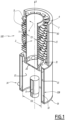
- Figures 1 and 3 illustrate two possible embodiments of a direct flame boiler according to claim 1, indicated as a whole by the reference number 100, which is adapted to be used in particular in a generator 200 of coolant vapor for thermal absorption machines, of which a possible exemplary embodiment, suitable for working fluids in which the absorbent is relatively volatile, is illustrated in Figure 5 .
- the generator 200 comprises a casing 201, that can be fabricated as one single metal piece or in multiple metal pieces connected to each other, for example in a cylindrical shaped form, which extends as a whole vertically along a substantially vertical reference axis Y.
- the boiler 100 when installed in the generator 200, substantially constitutes the base thereof and, as will become apparent in greater detail from the following description, is suitable to ensure that an initial solution containing a coolant substance is kept boiling so as to generate streams or flows of vapor containing this coolant.
- a solution comprising water and ammonia can be introduced into the boiler 100 through the duct 52 and/or the duct 53.
- the vapor streams first pass through, for example a stripping or analyzer section, schematically represented by the reference number 205 and then subsequently a dephlegmator, schematically represented by reference number 210.
- the stripping section 205 and the dephlegmator 210 are capable of altering the concentration of coolant in the vapors produced, in the event that a portion of these is constituted by the absorbent substance.
- This in particular, can be obtained by cooling at least the vapor streams V coming from the boiler 100 according to claim 1 so as to obtain a partial condensation of the absorbent, for example water, and thus increase the mass fraction of coolant, that is to say ammonia.
- this alteration occurs through the exchange of matter and/or heat between the vapors and the cooling fluids and/or materials used in the stripper and in the dephlegmator.
- the embodiments and modes of operation of both the stripping section 205 and the dephlegmator 210 may be of any type that is known in the art and/or easy to realize for a person skilled in the art; however, these embodiments and modalities are not relevant for the purposes of the description of the boiler 100 according to claim 1 and for these reasons they are not described herein in greater detail.
- the boiler 100 according to claim 1 comprises at least:
- a burner 11 capable of generating the heat necessary to ensure that the liquid solution present in the first internal cavity 2 and in the second internal cavity 13 is kept boiling, as will become apparent in greater detail from the following description.
- the fourth body 20 is interposed between the first body 1 and the second body 10, and is integrally connected to them, for example by means of welding.
- the fourth body 20 is also integrally connected to the top part of the third body 10B.
- the fourth body 20 is a cross-flow distributor, and in particular it is configured in a manner such that at least hot fumes produced by the burner 11, indicated in Figures 1 , 2 and 5 by the letters F c , flow through it flowing from the second internal cavity 12 towards the outer surfaces 6 of the first body 1, while streams of the boiling liquid solution, indicated in Figures 2 , 3 and 5 by the letter L, flow through it by flowing from the first internal cavity 2 of the body 1 down into the third internal cavity 13.
- its vertical reference axis X preferably coincides substantially with the axis Y along which the generator 200 as a whole is extended vertically.
- the first internal cavity 2 has an internal extension D1 measured in a transversal direction, and in particular perpendicular, to the vertical reference axis X, which is smaller than the maximum internal extension D2 of the second internal cavity 12, also measured in a transversal direction, and in particular perpendicular, to the vertical reference axis X.
- the streams L flow out from the boiler 100 through at least one duct 14 (illustrated for simplicity only in Figures 1 and 5 ) provided at the base of the third internal cavity 13 and which connects this cavity 13 to the exterior.
- the second body 10 comprises a first internal cylindrical body which laterally delimits said second internal cavity 12 and develops vertically around the substantially vertical reference axis X; this first internal cylindrical body 10 therefore has an internal diameter equal to D2.
- the third body 10B comprises a second external cylindrical body which is arranged externally to and substantially concentric with the first internal cylindrical body 10 relative to said substantially vertical axis X.
- the two cylindrical bodies 10 and 10B are arranged coaxially to each other around the vertical reference axis X which therefore actually constitutes the axis of structural symmetry, and they delimit there-between an interspace which forms the third internal cavity 13.
- the external cylindrical body 10B extends along the axis X, only for a short part beyond the first internal cylindrical body 10, and the third cavity 13 is closed at the bottom, for example by means of a metal plate 16 of the second body 10 welded to the two coaxial cylindrical bodies 10 and 10B, and at the top by means of the structure of the fourth body 20 welded to the same coaxial cylindrical bodies 10 and 10B.
- the burner 11 preferably has a substantially cylindrical shape and is arranged in the second cavity 12 in a central position extending along said vertical reference axis X which in fact also constitutes the axis of structural symmetry thereof.
- the first body 1 also comprises a substantially cylindrical body which develops vertically around the vertical reference axis X which in fact also constitutes the axis of structural symmetry thereof.
- the cylinder of the first body 1 has an internal diameter D1 smaller than the internal diameter D2 of the first cylindrical body 10.
- the first body 1 comprises at least a plurality of metal plates 9 which are suitably arranged in sequence with each other along the substantially vertical axis X inside the first cavity 2.
- the metal plates 9 are positioned mutually among them, in particular staggered, in a manner so as to form a passage pathway for the descending liquid solution (arrows L) or for the ascending vapors (arrows V) produced by boiling, and promote exchanges of mass and/or heat between the flows of liquid streams L and vapor streams V.
- the boiler 100 according to claim 1 further comprises a plurality of fins 5 which are fixed on the outer surface 6 of the first hollow body 1.
- a helical fin constituted of a segmented or notched metal strip 7 which is fixed on the outer surface 6 of the first hollow body 1 along substantially all or a predominant portion of the vertical extension thereof.
- the or each strip 7 protrudes from the outer surface 6 in a transversal direction, in particular perpendicular, relative to the vertical reference axis X, with its teeth that form the fins 5; advantageously, with respect to a direction parallel to the vertical reference axis X, the fins 5 are for example staggered between adjacent turns of the fins, in order to facilitate the through- passage of fumes.
- each metal strip 7 is high frequency resistance welded to the outer surface 6 of the first body 1, before the latter is welded to the fourth body or cross-flow distributor 20.
- the fins 5 may have a shorter length in the lower part of the body 1 where the temperatures, and therefore the heat exchanges, are greater.
- the length of the fins 5, measured along a transversal direction relative to the vertical reference axis X, increases in the ascending direction along the first body 1, that is to say in the direction moving away from the fourth body 20.
- each fin 5 comprises, seen in a plane perpendicular to the reference axis X, a shaped body having a U- shaped or C- shaped section; the U- or C-shaped body is fixed on the external surface 6 of the first body 1 and extends longitudinally along a direction parallel to the vertical reference axis X with the concavity facing outwards relative to the first body 1, that is to say in the direction opposite to the first internal cavity 2.
- the fins 5 are welded to the external wall 6 of the first hollow body 1 before the latter is welded to the fourth body 20.
- the boiler 100 comprises moreover, an insulating jacket 30 comprising at least one layer of thermal insulating material, for example glass wool, which is arranged laterally around the first body 1, and contained for example in a rigid cylindrical casing, for example made of metal.
- an insulating jacket 30 comprising at least one layer of thermal insulating material, for example glass wool, which is arranged laterally around the first body 1, and contained for example in a rigid cylindrical casing, for example made of metal.
- the insulating jacket 30 as a whole preferably has also a cylindrical shape that develops around the vertical axis X, which therefore constitutes the axis of symmetry thereof.
- the insulating jacket 30 extends above and upwards from the fourth body 20 along the vertical reference axis X, and is arranged laterally around the outer surface 6 of the first hollow body 1 and is spaced apart there-from so as to form with the first hollow body 1 an interspace 31 within which the fins 5 are housed and within which the hot fumes Fc flow.
- the rigid casing of the insulating jacket 30 is for example fixed below the cross- flow diffuser 20.
- the boiler 100 comprises a further metallic hollow cylindrical body 32 which is fixed at its bottom/lower part to the fourth body 20 and extends above and upwards along the substantially vertical reference axis X.
- said further metallic cylindrical body 32 is arranged laterally around and spaced apart from the first body 1 in a manner so as to delimit with it, at least in part, an interspace 31.
- the third external cylindrical body 10B is disposed externally to and extends further along the substantially vertical axis X also around the fourth body 20 and up to the further metallic hollow cylindrical body 32.
- the external cylindrical body 10B delimits with the first cylindrical body 10, the fourth body 20, and the further hollow insulating body 32, a further interspace or cavity 35 which, in the lower part, includes in fact also the second internal cavity 13.
- a heat exchanger 36 is housed within the interspace 35, for example a coil which extends for instance over the entire vertical length of the boiler 100 according to claim 1.
- Such a coil 36 for example makes it possible to drain the solution poor of coolant from the bottom of the boiler 100 and to release heat to the solution rich of coolant which instead travels in a countercurrent flow in the downward direction.
- an appropriate insulation may be used on the exterior of the third body 10B on the exterior of the third body 10B.
- the fourth hollow body 20 comprises one or more first through holes 21 which extend in a transversal direction, in particular perpendicular to the substantially vertical reference axis X.
- These first through holes 21 are configured to cause streams of solution L to flow out from the first internal cavity 2 conveying them towards the second body 10, and introducing them into the third cavity 13.
- the fourth body 20 conveniently comprises one or more second through holes 22 which extend in a direction substantially parallel to the vertical reference axis X.
- These second through holes 22 are configured in a manner such as to cause hot fumes Fc to flow out from the second internal cavity 12 making them rise upwards and directing them towards the exterior of the external lateral walls 6 of the first body 1.
- the streams of vapor, which form in the third internal cavity 13 are also able to rise upwards.
- the fourth body 20 also preferably presents a substantially symmetrical structure in relation to the reference axis X, and is for example made of steel.
- the fourth body 20 has a hollowed or flared central portion 23, shaped for example like a cup or glass, having the cavity facing towards the first body 1; along the lateral surface of the hollowed portion 23 is defined the inlet of said one or more first through holes 21 which then lead into the third internal cavity 13.
- the fourth body 20 comprises a lateral portion 24 which is arranged around the central portion 23 along which said one or more second through holes 22 are defined.
- the lateral portion 24 of the fourth body 20 has, for example, a ring shape in which the bottom part 25, for instance is welded to the first cylindrical body 10, and the top part has a laterally protruding flange 26 which is welded below the second cylinder body 10B and above the first body 1 and the metal cylinder which forms the insulating jacket 30.
- connections may be implemented differently; for example, the protruding flange 26 may be welded laterally to the second cylinder body 10B.
- the lateral portion 24 has at the top a raised inner edge 27 arranged around the hollowed central portion 23 that is adapted so as to be fixed, in particular welded, to the first body 1, and an outer edge 28 raised at the top and adapted so as to be fixed, for example welded, to the further body 32.
- the lateral portion 24 has at the bottom a further lower edge 29 adapted so as to be fixed, for example welded, to the first cylindrical body 10.
- the fourth body 20 in accordance with claim 1 can be differently configured and have any shape suitable for performing the tasks assigned to it, namely configured so that hot fumes Fc produced by the burner 11 flows through it flowing from said second internal cavity 12 towards the outer surface 6 of the first body 1, and flows of said liquid solution flow through it flowing from said first internal cavity 2 into said third internal cavity 13.
- the boiler 100 according to claim 1 may be conveniently installed for example at the base of a generator 200 for a thermal absorption machine.
- the mass and/or heat exchanges serve to enable at least partial condensation of the water contained in the vapor, thus going to increase the percentage of coolant obtained.
- the rectified coolant vapor (indicated in Figure 5 by the arrow V R ) is released from the generator head to be used, for example, in the refrigeration cycle of the thermal machine of which the generator 200 forms a part.
- the condensed vapor V flows downwards travelling along the pathway in the opposite direction and mixes with the liquid solution L entering into the generator.
- the boiler 100 according to claim 1 and the generator 200 according to the invention fulfil the intended scope and objects in that they allow realizing a very efficient solution from the thermal standpoint, and in particular wherein the heat dispersion or losses are reduced as compared to known solutions, the local tensions and related stresses in particular in the walls of the boiler, are at least reduced thanks also to the structure being substantially symmetrical, and the heat exchanges are optimized.
- the fins 5 serve to maximize heat transfer from the hot fumes Fc which rise and flow parallel to the axis X of the first hollow body 1 rather than perpendicularly thereto; therefore these fumes are forced to constantly change direction in order to pass through the interstices of the fins, consequently providing substantial improvement in respect of the turbulence and heat transfer coefficient.
- both the boiler 100 according to claim 1 and the generator 200 may be advantageously used for the fabrication of a thermal absorption machine, and in particular a heat pump or a chiller;
- a further aspect of the present invention constitutes a thermal absorption machine comprising a boiler 100 according to claim 1 or such a generator 20C according to claim 14
- a further aspect of the present invention constitutes a thermal absorption machine comprising a boiler 100 according to claim 1 or such a generator 20C according to claim 14
- the principle of the invention remaining the same, there may be wide variation in the embodiments and the particular details of implementation as compared to what has been described and illustrated purely by way of non-limiting example, without thereby intending to depart from the scope of protection of the present invention as defined in the attached claims.
- the components described could be made from a material that is different from that mentioned in the description and/or they could be configured differently from the manner described above as long as compatibility thereof is ensured with respect to the scope of the following claims, for example, the fins 5 may easily be bent or twisted, in order to modify the area of throughpassage of the flue gases.
Landscapes
- Engineering & Computer Science (AREA)
- Power Engineering (AREA)
- Physics & Mathematics (AREA)
- Mechanical Engineering (AREA)
- Thermal Sciences (AREA)
- General Engineering & Computer Science (AREA)
- Heat-Exchange Devices With Radiators And Conduit Assemblies (AREA)
- Sorption Type Refrigeration Machines (AREA)
Claims (15)
- Direktflammkessel (100), wobeier mindestens Folgendes umfasst:- einen ersten Körper (1), der sich entlang einer im Wesentlichen vertikalen Bezugsachse (X) erstreckt und zumindest teilweise einen ersten inneren Hohlraum (2) umschließt, der zum Aufnehmen einer flüssigen Lösung geeignet ist;- einen zweiten Körper (10), der in Bezug auf die im Wesentlichen vertikale Achse (X) unter dem ersten Körper (2) angeordnet ist und zumindest teilweise einen zweiten inneren Hohlraum (12) umschließt, in dem ein Brenner (11) platziert ist, der in der Lage ist, Wärme zu erzeugen, um die flüssige Lösung in dem ersten inneren Hohlraum (2) am Sieden zu halten;- einen dritten Körper (10B), der zumindest teilweise um den zweiten Körper (10) herum angeordnet ist, wobei der zweite und der dritte Körper (10, 10B) untereinander einen dritten inneren Hohlraum (13) begrenzen, der zumindest teilweise seitlich um den zweiten Hohlraum (12) herum angeordnet ist; und- einen vierten Körper (20), der zwischen dem ersten Körper (1) und dem zweiten Körper (10) angeordnet und zumindest einstückig damit verbunden ist, wobei der vierte Körper (20) konfiguriert ist, sodass heiße Rauchgase (Fc), die von dem Brenner (11) erzeugt werden, durch ihn strömen und von dem zweiten inneren Hohlraum (12) zu der äußeren Oberfläche (6) des ersten Körpers (1) strömen, und dadurch gekennzeichnet, dass der vierte Körper (20) konfiguriert ist, sodassStröme der flüssigen Lösung durch ihn strömen und von dem ersten inneren Hohlraum (2) in den dritten inneren Hohlraum (13) strömen, wobei der vierte Körper (20) ein oder mehrere erste Durchgangslöcher (21) umfasst, die sich in einer Richtung quer zu der im Wesentlichen vertikalen Bezugsachse (X) erstrecken und konfiguriert sind, um den ersten inneren Hohlraum (2) mit dem dritten inneren Hohlraum (13) in Verbindung bringen.
- Kessel (100) nach Anspruch 1, wobei der vierte Körper (20) ein oder mehrere zweite Durchgangslöcher (22) umfasst, die sich in einer Richtung im Wesentlichen parallel zu der im Wesentlichen vertikalen Bezugsachse (X) erstrecken und konfiguriert sind, um den zweiten inneren Hohlraum (2) mit einem Außenbereich um den ersten Körper (1) herum in Verbindung bringen.
- Kessel (100) nach Anspruch 2, wobei der vierte Körper (20) einen mittleren Abschnitt (23), der mit dem Hohlraum zu dem ersten Körper (1) hin hohl ist und entlang dessen Seitenfläche der Einlass des einen oder der mehreren ersten Durchgangslöcher (21) definiert ist, und einen seitlichen Abschnitt
(24), der um den mittleren Abschnitt (23) herum angeordnet ist, entlang dessen das eine oder die mehreren zweiten Durchgangslöcher (22) definiert sind, umfasst. - Kessel (100) nach einem oder mehreren der vorherigen Ansprüche, wobei der zweite Körper (10) einen ersten inneren zylindrischen Körper umfasst, der den zweiten inneren Hohlraum (12) seitlich begrenzt, und der dritte Körper (10B) einen zweiten äußeren zylindrischen Körper umfasst, der außerhalb des ersten inneren zylindrischen Körpers und im Wesentlichen konzentrisch zu diesem in Bezug auf die im Wesentlichen vertikale Achse (X) angeordnet ist, wobei der dritte innere Hohlraum (13) zumindest teilweise zwischen dem ersten inneren zylindrischen Körper und dem zweiten äußeren zylindrischen Körper definiert ist.
- Kessel (100) nach einem oder mehreren der vorherigen Ansprüche, wobei der Brenner (11) eine im Wesentlichen zylindrische Form aufweist und in dem zweiten Hohlraum (12) an einer mittleren Position angeordnet ist, die sich von einer Grundplatte (16) entlang der im Wesentlichen vertikalen Bezugsachse (X) erstreckt.
- Kessel (100) nach einem oder mehreren der vorherigen Ansprüche, wobei der erste Körper (1) einen im Wesentlichen zylindrischen Körper umfasst, der sich vertikal um die im Wesentlichen vertikale Bezugsachse (X) erstreckt und einen Innendurchmesser (D1) aufweist, der kleiner als oder gleich wie der Innendurchmesser (D2) des zweiten inneren Hohlraums (12) ist.
- Kessel (100) nach einem oder mehreren der vorherigen Ansprüche, umfassend eine Vielzahl von Metallplatten (9), die im Inneren des ersten inneren Hohlraums (2) hintereinander entlang der im Wesentlichen vertikalen Achse (X) angeordnet sind.
- Kessel (100) nach einem oder mehreren der vorherigen Ansprüche, umfassend eine Vielzahl von Rippen (5), die an der Außenfläche (6) des ersten Körpers (1) befestigt sind.
- Kessel (100) nach Anspruch 8, wobei die Vielzahl von Rippen (5) durch mindestens einen segmentierten Metallstreifen gebildet ist, der schraubenförmig an der Außenfläche (6) des ersten Hohlkörpers (1) befestigt ist und von der Außenfläche in einer Querrichtung in Bezug auf
die im Wesentlichen vertikale Bezugsachse (X) hervorsteht. - Kessel (100) nach Anspruch 8, wobei jede der Rippen (5) einen U- oder C-förmigen Körper umfasst, der an der Außenfläche (6) des ersten Körpers (1) befestigt ist und sich in Längsrichtung entlang der im Wesentlichen vertikalen Bezugsachse (X) erstreckt, wobei die Konkavität
in Bezug auf den ersten Körper (1) nach außen gerichtet ist. - Kessel (100) nach einem oder mehreren der vorherigen Ansprüche, umfassend einen Isoliermantel (30), der seitlich um den ersten Körper (1) herum und in einem Abstand davon angeordnet ist, um zusammen damit zumindest teilweise einen Zwischenraum (31) abzugrenzen.
- Kessel (100) nach einem oder mehreren der Ansprüche 1 bis 10, umfassend einen weiteren hohlen zylindrischen Körper (32), der in seinem unteren Teil an dem vierten Körper (20) befestigt ist und sich entlang der im Wesentlichen vertikalen Bezugsachse (X) nach oben erstreckt, wobei der weitere zylindrische Körper (30) seitlich um den ersten Körper (1) herum und davon beabstandet angeordnet ist, sodass er damit zumindest teilweise einen Zwischenraum (31) begrenzt.
- Kessel (100) nach Anspruch 12, wenn abhängig von Anspruch 4, wobei der zweite äußere zylindrische Körper (10B) außerhalb der im Wesentlichen vertikalen Achse (X) um den vierten Körper (20) und den weiteren hohlen zylindrischen Körper (32) angeordnet ist und sich weiter entlang dieser Achse erstreckt, wobei der zweite äußere zylindrische Körper (10B) mit dem ersten zylindrischen Körper (10), dem vierten Körper (20) und dem weiteren hohlen Körper (32) einen Zwischenraum (35) begrenzt, der zum Aufnehmen eines Wärmetauschers (36) geeignet ist.
- Kältemitteldampferzeuger (200) für Wärmeabsorptionsmaschinen, dadurch gekennzeichnet, dass er mindestens einen Direktflammkessel (100) nach einem oder mehreren der vorherigen Ansprüche umfasst.
- Wärmeabsorptionsmaschine, dadurch gekennzeichnet, dass sie einen Kältemitteldampferzeuger (200)nach Anspruch 14 oder einen Direktflammkessel(100) nach einem oder mehreren der Ansprüche 1-13 umfasst.
Applications Claiming Priority (2)
| Application Number | Priority Date | Filing Date | Title |
|---|---|---|---|
| IT102021000018272A IT202100018272A1 (it) | 2021-07-12 | 2021-07-12 | Boiler a fiamma diretta, in particolare per un generatore di vapore refrigerante per macchine termiche ad assorbimento, e generatore comprendente un tale boiler |
| PCT/EP2022/069321 WO2023285381A1 (en) | 2021-07-12 | 2022-07-11 | Direct flame boiler, in particular for a generator of coolant vapor for absorption thermal machines, and generator including such a boiler |
Publications (3)
| Publication Number | Publication Date |
|---|---|
| EP4370846A1 EP4370846A1 (de) | 2024-05-22 |
| EP4370846B1 true EP4370846B1 (de) | 2025-02-12 |
| EP4370846C0 EP4370846C0 (de) | 2025-02-12 |
Family
ID=77989918
Family Applications (1)
| Application Number | Title | Priority Date | Filing Date |
|---|---|---|---|
| EP22741296.2A Active EP4370846B1 (de) | 2021-07-12 | 2022-07-11 | Direktflammenkessel für wärmeabsorptionsmaschinen und dampferzeuger mit einem solchen kessel |
Country Status (4)
| Country | Link |
|---|---|
| EP (1) | EP4370846B1 (de) |
| CN (1) | CN117940720A (de) |
| IT (1) | IT202100018272A1 (de) |
| WO (1) | WO2023285381A1 (de) |
Family Cites Families (3)
| Publication number | Priority date | Publication date | Assignee | Title |
|---|---|---|---|---|
| US1729355A (en) * | 1926-03-16 | 1929-09-24 | Electrolux Servel Corp | Refrigerating apparatus of the absorption type |
| US5791158A (en) * | 1995-06-07 | 1998-08-11 | Gas Research Institute | Internally fired generator with improved solution flow |
| US5617737A (en) * | 1995-08-02 | 1997-04-08 | The Ohio State University Research Foundation | Capillary fluted tube mass and heat transfer devices and methods of use |
-
2021
- 2021-07-12 IT IT102021000018272A patent/IT202100018272A1/it unknown
-
2022
- 2022-07-11 WO PCT/EP2022/069321 patent/WO2023285381A1/en not_active Ceased
- 2022-07-11 EP EP22741296.2A patent/EP4370846B1/de active Active
- 2022-07-11 CN CN202280049461.0A patent/CN117940720A/zh active Pending
Also Published As
| Publication number | Publication date |
|---|---|
| EP4370846A1 (de) | 2024-05-22 |
| EP4370846C0 (de) | 2025-02-12 |
| CN117940720A (zh) | 2024-04-26 |
| WO2023285381A1 (en) | 2023-01-19 |
| IT202100018272A1 (it) | 2023-01-12 |
Similar Documents
| Publication | Publication Date | Title |
|---|---|---|
| EP2766685B1 (de) | Hybrider wärmetauscher mit gas-wasser-rohrkombination | |
| US9797622B2 (en) | Coil and serpentine bent fin tube condensing heat exchanger | |
| US20150300687A1 (en) | A Straight Fin Tube with Bended Fins Condensing Heat Exchanger | |
| US20150007779A1 (en) | Spiral finned coil condensing heat exchanger | |
| US9470433B2 (en) | Dual-ring and straight fin tube condensing | |
| JPWO1999024769A1 (ja) | 吸収冷温水機及びその高温再生器 | |
| WO1998046948A1 (en) | Solar driven ammonia-absorption cooling machine | |
| CN110285695A (zh) | 套筒式通道换热器 | |
| EP3236175A1 (de) | Wärmetauscher | |
| KR20140051760A (ko) | 친환경 열교환기 | |
| CA2556470C (en) | Single pass fuel-fired fluid heating/storage device | |
| EP4370846B1 (de) | Direktflammenkessel für wärmeabsorptionsmaschinen und dampferzeuger mit einem solchen kessel | |
| WO2008078211A1 (en) | A heat exchanger | |
| CN214950785U (zh) | 一种热管节能器 | |
| KR100228032B1 (ko) | 가스보일러의 콘덴싱열교환기 | |
| RU2449224C1 (ru) | Конденсационный котел наружного размещения | |
| CN201335535Y (zh) | 容积式冷凝燃气炉换热装置 | |
| US4468934A (en) | Absorption refrigeration system | |
| CN214250700U (zh) | 一种蒸汽发生装置用模块组合换热器 | |
| US20260055927A1 (en) | Heater Exchanger for Water Heaters | |
| CN213901503U (zh) | 一种燃气热水设备的二次冷凝换热器 | |
| CN211823961U (zh) | 一种吸氨蒸氨两用换热器 | |
| WO2026050066A1 (en) | Heater exchangers for water heaters | |
| CN118043620A (zh) | 吸收式热泵用火焰管换热器 | |
| KR100391257B1 (ko) | 난방 및 온수를 위한 상향연소 콘덴싱 보일러의 열교환기 |
Legal Events
| Date | Code | Title | Description |
|---|---|---|---|
| STAA | Information on the status of an ep patent application or granted ep patent |
Free format text: STATUS: UNKNOWN |
|
| STAA | Information on the status of an ep patent application or granted ep patent |
Free format text: STATUS: THE INTERNATIONAL PUBLICATION HAS BEEN MADE |
|
| PUAI | Public reference made under article 153(3) epc to a published international application that has entered the european phase |
Free format text: ORIGINAL CODE: 0009012 |
|
| STAA | Information on the status of an ep patent application or granted ep patent |
Free format text: STATUS: REQUEST FOR EXAMINATION WAS MADE |
|
| 17P | Request for examination filed |
Effective date: 20240109 |
|
| AK | Designated contracting states |
Kind code of ref document: A1 Designated state(s): AL AT BE BG CH CY CZ DE DK EE ES FI FR GB GR HR HU IE IS IT LI LT LU LV MC MK MT NL NO PL PT RO RS SE SI SK SM TR |
|
| GRAP | Despatch of communication of intention to grant a patent |
Free format text: ORIGINAL CODE: EPIDOSNIGR1 |
|
| STAA | Information on the status of an ep patent application or granted ep patent |
Free format text: STATUS: GRANT OF PATENT IS INTENDED |
|
| DAV | Request for validation of the european patent (deleted) | ||
| DAX | Request for extension of the european patent (deleted) | ||
| INTG | Intention to grant announced |
Effective date: 20240903 |
|
| GRAS | Grant fee paid |
Free format text: ORIGINAL CODE: EPIDOSNIGR3 |
|
| GRAA | (expected) grant |
Free format text: ORIGINAL CODE: 0009210 |
|
| STAA | Information on the status of an ep patent application or granted ep patent |
Free format text: STATUS: THE PATENT HAS BEEN GRANTED |
|
| AK | Designated contracting states |
Kind code of ref document: B1 Designated state(s): AL AT BE BG CH CY CZ DE DK EE ES FI FR GB GR HR HU IE IS IT LI LT LU LV MC MK MT NL NO PL PT RO RS SE SI SK SM TR |
|
| REG | Reference to a national code |
Ref country code: GB Ref legal event code: FG4D |
|
| REG | Reference to a national code |
Ref country code: CH Ref legal event code: EP |
|
| REG | Reference to a national code |
Ref country code: DE Ref legal event code: R096 Ref document number: 602022010588 Country of ref document: DE |
|
| REG | Reference to a national code |
Ref country code: IE Ref legal event code: FG4D |
|
| U01 | Request for unitary effect filed |
Effective date: 20250310 |
|
| U07 | Unitary effect registered |
Designated state(s): AT BE BG DE DK EE FI FR IT LT LU LV MT NL PT RO SE SI Effective date: 20250318 |
|
| PG25 | Lapsed in a contracting state [announced via postgrant information from national office to epo] |
Ref country code: RS Free format text: LAPSE BECAUSE OF FAILURE TO SUBMIT A TRANSLATION OF THE DESCRIPTION OR TO PAY THE FEE WITHIN THE PRESCRIBED TIME-LIMIT Effective date: 20250512 |
|
| PG25 | Lapsed in a contracting state [announced via postgrant information from national office to epo] |
Ref country code: PL Free format text: LAPSE BECAUSE OF FAILURE TO SUBMIT A TRANSLATION OF THE DESCRIPTION OR TO PAY THE FEE WITHIN THE PRESCRIBED TIME-LIMIT Effective date: 20250212 |
|
| PG25 | Lapsed in a contracting state [announced via postgrant information from national office to epo] |
Ref country code: ES Free format text: LAPSE BECAUSE OF FAILURE TO SUBMIT A TRANSLATION OF THE DESCRIPTION OR TO PAY THE FEE WITHIN THE PRESCRIBED TIME-LIMIT Effective date: 20250212 |
|
| PG25 | Lapsed in a contracting state [announced via postgrant information from national office to epo] |
Ref country code: NO Free format text: LAPSE BECAUSE OF FAILURE TO SUBMIT A TRANSLATION OF THE DESCRIPTION OR TO PAY THE FEE WITHIN THE PRESCRIBED TIME-LIMIT Effective date: 20250512 Ref country code: IS Free format text: LAPSE BECAUSE OF FAILURE TO SUBMIT A TRANSLATION OF THE DESCRIPTION OR TO PAY THE FEE WITHIN THE PRESCRIBED TIME-LIMIT Effective date: 20250612 |
|
| PG25 | Lapsed in a contracting state [announced via postgrant information from national office to epo] |
Ref country code: HR Free format text: LAPSE BECAUSE OF FAILURE TO SUBMIT A TRANSLATION OF THE DESCRIPTION OR TO PAY THE FEE WITHIN THE PRESCRIBED TIME-LIMIT Effective date: 20250212 |
|
| PG25 | Lapsed in a contracting state [announced via postgrant information from national office to epo] |
Ref country code: GR Free format text: LAPSE BECAUSE OF FAILURE TO SUBMIT A TRANSLATION OF THE DESCRIPTION OR TO PAY THE FEE WITHIN THE PRESCRIBED TIME-LIMIT Effective date: 20250513 |
|
| U20 | Renewal fee for the european patent with unitary effect paid |
Year of fee payment: 4 Effective date: 20250729 |
|
| PG25 | Lapsed in a contracting state [announced via postgrant information from national office to epo] |
Ref country code: SM Free format text: LAPSE BECAUSE OF FAILURE TO SUBMIT A TRANSLATION OF THE DESCRIPTION OR TO PAY THE FEE WITHIN THE PRESCRIBED TIME-LIMIT Effective date: 20250212 |
|
| PG25 | Lapsed in a contracting state [announced via postgrant information from national office to epo] |
Ref country code: CZ Free format text: LAPSE BECAUSE OF FAILURE TO SUBMIT A TRANSLATION OF THE DESCRIPTION OR TO PAY THE FEE WITHIN THE PRESCRIBED TIME-LIMIT Effective date: 20250212 |
|
| PG25 | Lapsed in a contracting state [announced via postgrant information from national office to epo] |
Ref country code: SK Free format text: LAPSE BECAUSE OF FAILURE TO SUBMIT A TRANSLATION OF THE DESCRIPTION OR TO PAY THE FEE WITHIN THE PRESCRIBED TIME-LIMIT Effective date: 20250212 |
|
| PLBE | No opposition filed within time limit |
Free format text: ORIGINAL CODE: 0009261 |
|
| STAA | Information on the status of an ep patent application or granted ep patent |
Free format text: STATUS: NO OPPOSITION FILED WITHIN TIME LIMIT |
|
| REG | Reference to a national code |
Ref country code: CH Ref legal event code: L10 Free format text: ST27 STATUS EVENT CODE: U-0-0-L10-L00 (AS PROVIDED BY THE NATIONAL OFFICE) Effective date: 20251224 |
|
| 26N | No opposition filed |
Effective date: 20251113 |
|
| REG | Reference to a national code |
Ref country code: CH Ref legal event code: H13 Free format text: ST27 STATUS EVENT CODE: U-0-0-H10-H13 (AS PROVIDED BY THE NATIONAL OFFICE) Effective date: 20260224 |