EP4368348B1 - Elektrische nagelpistole - Google Patents
Elektrische nagelpistole Download PDFInfo
- Publication number
- EP4368348B1 EP4368348B1 EP23207047.4A EP23207047A EP4368348B1 EP 4368348 B1 EP4368348 B1 EP 4368348B1 EP 23207047 A EP23207047 A EP 23207047A EP 4368348 B1 EP4368348 B1 EP 4368348B1
- Authority
- EP
- European Patent Office
- Prior art keywords
- nail
- muzzle
- main body
- hammer
- unit
- Prior art date
- Legal status (The legal status is an assumption and is not a legal conclusion. Google has not performed a legal analysis and makes no representation as to the accuracy of the status listed.)
- Active
Links
Images


Classifications
-
- B—PERFORMING OPERATIONS; TRANSPORTING
- B25—HAND TOOLS; PORTABLE POWER-DRIVEN TOOLS; MANIPULATORS
- B25C—HAND-HELD NAILING OR STAPLING TOOLS; MANUALLY OPERATED PORTABLE STAPLING TOOLS
- B25C1/00—Hand-held nailing tools; Nail feeding devices
- B25C1/06—Hand-held nailing tools; Nail feeding devices operated by electric power
Definitions
- the invention relates to an electric nail gun, and more particularly to an electric nail gun, according to the preamble of claim 1, for providing repeated hammer blows.
- an electric nail gun is known from US 3 299 967 A .
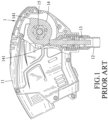
- a conventional percussion device 1 disclosed in Chinese Patent Publication No. 102844154 includes a housing 11, a sleeve 12, an impact member 13, a hammer 14, and a helical gear 15.
- the sleeve 12 is movable relative to the housing 11.
- the impact member 13 is movably disposed in the sleeve 12 and is adapted for striking a nail (not shown).
- the hammer 14 is disposed in the housing 11, is rotatable about an axis (not shown), and is operable to strike the impact member 13.
- the helical gear 15 is driven by a motor (not shown) to rotate about the axis, and releasably engages the hammer 14.
- the hammer 14 is urged by the helical gear 15 to rotate about the axis when the hammer 14 engages the helical gear 15, and has two protruding portions 141 that are spaced apart from each other.
- the helical gear 15 urges the hammer 14 to rotate to a position in which one of the protruding portions 141 of the hammer 14 strikes the impact member 13, the hammer 14 is refrained from rotating with the helical gear 15. At this time, the helical gear 15 continues to rotate, and the hammer 14 is released from the helical gear 15 such that the hammer 14 moves along an outer peripheral surface of the helical gear 15 in a direction of the axis and compresses a resilient member (not shown).
- the impact member 13 hammers the nail such that the nail is driven into an object (not shown). Therefore, when the impact member 13 is alternately struck by the protruding portions 141 of the hammer 14, the conventional percussion device 1 may provide repeated hammering blows to repeatedly hammer the nail.
- the sleeve 12 is gradually retracted into the housing 11 as the nail is gradually hammered deeply into the object so that the impact member 13 may be kept close to the nail.
- the energy stored in the resilient member when the resilient member is compressed by the hammer 14 is used not only for accelerating the rotation of the hammer 14 and the helical gear 15, but also for driving linear movement of the hammer 14 in the direction opposite to the direction of the axis. That is to say, the energy provided by the resilient member has to be transferred to the nail through the hammer 14 and the helical gear 15 (i.e., the energy is not directly transferred to the nail).
- the energy transmission path may be relatively long, and a large amount of the energy may be lost before the energy is transferred to the nail.
- the conventional percussion device 1 may not be able to stop striking the nail when the nail has been driven into the object deeply. A user has to determine when to stop operating the conventional percussion device 1 by observing the length of the sleeve 12. The conventional percussion device 1 is therefore not user-friendly.
- an object of the disclosure is to provide an electric nail gun that can alleviate at least one of the drawbacks of the prior art.
- the invention provides an electric nail gun according to claim 1.
- the electric nail gun further includes a housing that covers the main body unit 3 and the motor unit 7.
- the housing is not shown in the drawings of the disclosure.
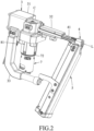
- the main body unit 3 includes a main body 31, a sleeve 32 that is connected to the main body 31 and that is elongated along a main axis (L), and a grip 33 that is connected to the main body 31 and that is substantially L-shaped.
- the main body 31 has an inner surface 311 that defines an energy storage space 310.
- the sleeve 32 surrounds the main axis (L) to define a passage 320 that is in spatial communication with the energy storage space 310.
- the muzzle unit 4 includes a muzzle 41 that is disposed on the sleeve 32 and that is movable relative to the sleeve 32, and a resilient member 42 that is disposed in the passage 320.
- the muzzle 41 extends into the passage 320, is movable relative to the passage 320 along the main axis (L), and surrounds the main axis (L) to define a nail-accommodating space 410 that is in spatial communication with the passage 320.
- the muzzle 41 has a nail outlet 411 that is spaced apart from the passage 320 and that is formed at one end thereof, and a nail inlet 412 that is in spatial communication with the nail-accommodating space 410 and that is located between the nail outlet 411 and the sleeve 32 along the main axis (L).
- the nail inlet 412 is adapted for the nail 21 to enter the nail-accommodating space 410 therethrough.
- the nail-accommodating space 410 is adapted for accommodating the nail 21.
- the nail outlet 411 is adapted for allowing the nail 21 to exit the nail-accommodating space 410.
- the resilient member 42 is a compression spring, and has two opposite ends that respectively abut against the muzzle 41 and the sleeve 32 of the main body unit 3.
- the magazine unit 5 is co-movably connected to the muzzle 41 such that the magazine unit 5 is movable relative to the main body unit 3 along the main axis (L).
- the magazine unit 5 is adapted for conveying the nail 21 through the nail inlet 412 into the nail-accommodating space 410.
- the hammer unit 6 is disposed on the main body unit 3 and the muzzle unit 4, and includes a hammer member 61 and a resilient member 62.
- the hammer member 61 is movable along the main axis (L), and is adapted for striking the nail 21.
- the hammer member 61 extends from the energy storage space 310 through the passage 320 into the nail-accommodating space 410, and is movable relative to the energy storage space 310, the passage 320, and the nail-accommodating space 410 along the main axis (L).
- the hammer member 61 includes a sliding seat 611 and a firing pin 612.
- the sliding seat 611 is disposed in the energy storage space 310, is slidable on the inner surface 311 of the main body 31, and abuts against the resilient member 62 of the hammer unit 6.
- the firing pin 612 is connected to the sliding seat 611, extends through the passage 320 into the nail-accommodating space 410, and is adapted for striking the nail 21 in the nail-accommodating space 410.
- the firing pin 612 has an abutting portion 613 that is formed on one side thereof, and that is located in the main body 31.
- the resilient member 62 has two opposite ends that respectively abut against the sliding seat 611 of the hammer member 61 and the main body 31.
- the resilient member 62 constantly provides a hammer restoring force for the hammer member 61 to move in a striking direction (X1) for striking the nail 21.
- the motor unit 7 is mounted to the main body unit 3, and includes a lifting wheel 71 and a motor module 72.
- the lifting wheel 71 is mounted to the main body 31, and is rotatable about a rotation axis (C).
- the motor module 72 is mounted to the main body 31, and is operable to urge the lifting wheel 71 to rotate.
- the rotation axis (C) is substantially orthogonal to the striking direction (X1).
- the lifting wheel 71 has four pushing portions 711 that are equiangularly spaced apart from each other about the rotation axis (C), and that are adjacent to an outer circumferential surface of the lifting wheel 71.
- the abutting portion 613 of the hammer member 61 separably engages one of the pushing portions 711 of the lifting wheel 71 at one time.
- Each of the pushing portions 711 when engaging the abutting portion 613 of the hammer member 61, is operable to push the hammer member 61 to move in an energy storage direction (X2) opposite to the striking direction (X1) such that the resilient member 62 of the hammer unit 6 is compressed by the hammer member 61 and provides the hammer restoring force to the hammer member 61.
- the control unit 8 includes a trigger subunit 81, a sensing subunit 82, a control subunit 83, and a battery subunit 84.
- the trigger subunit 81 is mounted to the grip 33, and is operable by a user when the user holds the grip 33.
- the sensing subunit 82 is mounted to the main body unit 3 and the muzzle 41.
- the control subunit 83 is signally coupled to the trigger subunit 81, the sensing subunit 82, and the motor module 72.
- the battery subunit 84 provides electric energy for the motor module 72 and the control subunit 83.
- the sensing subunit 82 includes a target member 821 and two sensing members 822.
- the target member 821 is a magnetic component, and is co-movably disposed on another end of the muzzle 41 that faces the energy storage space 310 and that is opposite to the one end of the muzzle 41 at which the nail outlet 411 is formed.
- the sensing members 822 are disposed on the sleeve 32 and are spaced apart from each other along the main axis (L).
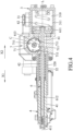
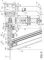
- the muzzle 41 is movable relative to the sleeve 32 among a standby position (see Fig. 3 ), an activation position (see Fig. 5 ), and a cessation position (see Fig. 9 ) along the main axis (L).
- the muzzle 41 when the muzzle 41 is in the standby position, a distance between the nail outlet 411 and the energy storage space 310 is at the longest, and the target member 821 is located at one side of the sensing members 822 opposite to the energy storage space 310 in the striking direction (X1), and is not located in a sensing area of any one of the sensing members 822.
- the sliding seat 611 is located at its bottom dead center in the energy storage space 310, and the abutting portion 613 of the firing pin 612 engages one of the pushing portions 711 of the lifting wheel 71.
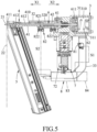
- the muzzle 41 when the muzzle 41 is in the activation position, the muzzle 41 is pushed in the energy storage direction (X2) and compresses the resilient member 42 such that the resilient member 42 provides a muzzle restoring force for the muzzle 41 to move in the striking direction (X1) to the standby position.
- a distance between the nail outlet 411 and the energy storage space 310 is shorter than the distance between the nail outlet 411 and the energy storage space 310 when the muzzle 41 in the standby position (i.e., the muzzle 41 approaches the energy storage space 310 when moving from the standby position to the activation position along the main axis (L)).
- the target member 821 is co-movably disposed on the muzzle 41; thus, when the muzzle 41 is in the activation position, the target member 821 is located in the sensing area of one of the sensing members 822 (hereinafter “the left-side sensing member 822") that is distal from the energy storage space 310.
- the muzzle 41 will be in the cessation position when being pushed in the energy storage direction (X2) from the activation position.
- a distance between the nail outlet 411 and the energy storage space 310 is shorter than the distance between the nail outlet 411 and the energy storage space 310 when the muzzle 41 in the activation position. That is to say, the muzzle 41 is distal from the energy storage space 310 when in the activation position, and is proximate to the energy storage space 310 when in the cessation position.
- the resilient member 42 constantly provides the muzzle restoring force for the muzzle 41 to move away from the cessation position to the standby position.
- the target member 821 is located in the sensing area of another one of the sensing members 822 (hereinafter “the right-side sensing member 822") that is proximate to the energy storage space 310.
- the muzzle 41 is in the standby position (see Fig. 3 ).
- the trigger subunit 81 When a user wants to strike a nail into an object 22 via the electric nail gun, the user has to operate the trigger subunit 81.
- the trigger subunit 81 generates a trigger signal (S1) when being operated.
- the user places the muzzle 41 so that the muzzle 41 abuts against the object 22, and exerts a force on the object 22 so that the muzzle 41 is pushed in the energy storage direction (X2) from the standby position to the activation position (see Fig. 5 ) by the object 22.
- the target member 821 is moved into the sensing area of the left-side sensing member 822, and the left-side sensing member 822 senses the target member 821 and generates an activation signal (S2) accordingly (i.e., the left-side sensing member 822 generates the activation signal (S2) when the muzzle 41 is in the activation position).
- the control subunit 83 activates the motor module 72 when receiving the trigger signal (S1) generated by the trigger subunit 81 and the activation signal (S2) generated by the left-side sensing member 822.
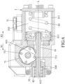
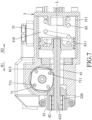
- the motor module 72 urges the lifting wheel 71 to rotate in a counterclockwise direction (viewing from Figs. 6 to 8 ) via the electric energy from the battery subunit 84.
- the lifting wheel 71 rotates, the abutting portion 613 of the firing pin 612 is pushed by the one of the pushing portions 711 that the abutting portion 613 engages to move in the energy storage direction (X2), thereby urging the sliding seat 611 to slide on the inner surface 311 in the energy storage direction (X2) to its top dead center in the energy storage space 310 (see Fig. 7 ).
- the resilient member 62 is compressed by the sliding seat 611 and provides the hammer restoring force to the hammer member 61.
- the one of the pushing portions 711 that the abutting portion 613 engages will be separated from the abutting portion 613, and then another one of the pushing portions 711 will engage the abutting portion 613.
- the resilient member 62 returns from being compressed such that the sliding seat 611 is urged to move toward its bottom dead center in the striking direction (X1) by the hammer restoring force provided by the resilient member 62, and the sliding seat 611 urges the firing pin 612 to move in the striking direction (X1) so that the firing pin 612 strikes the nail 21 and urges the nail 21 to exit the nail-accommodating space 410 through the nail outlet 411.
- the nail 21 is hammered into the object 22 in the striking direction (X1).
- the pushing portions 711 take turns pushing the hammer member 61 in the energy storage direction (X2) to compress the resilient member 62 so that the resilient member 62 repeatedly urges the hammer member 61 to move in the striking direction (X1) via the hammer restoring force to strike the nail 21. Therefore, the electric nail gun may repeatedly strike the nail 21.
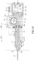
- Fig. 10 in cooperation with Fig. 9 , it is noted that the more times the electric nail gun strikes the nail 21, the deeper the nail 21 penetrates the object 22 and the less the nail 21 is exposed from the object 22. Therefore, the length of the nail 21 outside the object 22 gets shorter as the electric nail gun continuously strikes the nail 21.
- the muzzle 41 is moved in the energy storage direction (X2) so that the muzzle 41 is gradually retracted into the sleeve 32.
- the target member 821 is moved into the sensing area of the right-side sensing member 822, and the right-side sensing member 822 senses the target member 821 and generates a stop signal (S3) accordingly (i.e., the right-side sensing member 822 generates the stop signal (S3) when the muzzle 41 is in the cessation position).
- the control subunit 83 turns the motor module 72 off when receiving the stop signal (S3).
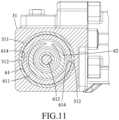
- the main body 31 may further have two body-coupling portions 312 that are formed on the inner surface 311, and the sliding seat 611 may have two seat-coupling portions 614 that are formed on an outer surface thereof, and that are respectively and slidably engaged with the body-coupling portions 312 of the main body 31.
- each of the body-coupling portions 312 is configured as a protrusion
- each of the seat-coupling portions 614 is configured as a recess.
- each of the body-coupling portions 312 may be configured as a recess while each of the seat-coupling portions 614 may be configured as a protrusion.
- the body-coupling portions 312 may respectively be configured as a recess and a protrusion while the seat-coupling portions 614 may respectively be configured as a protrusion and a recess.
- the sliding seat 611 may slide on the inner surface 311 of the main body 31 more steadily.
- the quantity of the pushing portions 711 of the lifting wheel 71 may not be limited to 4. In certain embodiments, the quantity of the pushing portions 711 may be any positive integer according to actual requirements.
- the control subunit 83 may activate the motor module 72 even when the order in which the trigger signal (S1) and the activation signal (S2) are received by the control subunit 83 is reversed. That is to say, the motor module 72 may also be activated by the control subunit 83 even if the user places the muzzle 41 in the activation position before operating the trigger subunit 81.
- the control subunits 83 and the signals since the relevant mechanism is widely-understood by those skilled in the art and various configurations are known.
- the electric nail gun may repeatedly strike the nail 21 via a simple mechanism, and energy transmission path from the resilient member 62 to the nail 21 may be shortened, which reduces energy waste.
- the control unit 8 is capable of turning the motor module 72 off according to the location of the muzzle 41, the electric nail gun may stop striking the nail 21 when the nail 21 has been completely hammered into the object 22. Therefore, a user will not have to determine when he/she should stop operating the electric nail gun.
- the electric nail gun is user-friendly.
Landscapes
- Engineering & Computer Science (AREA)
- Mechanical Engineering (AREA)
- Portable Nailing Machines And Staplers (AREA)
Claims (12)
- Elektrisches Nagelgerät, das Folgendes umfasst:eine Hauptkörpereinheit (3),eine Mündungseinheit (4),eine Hammereinheit (6),eine Motoreinheit (7) undeine Steuerungseinheit (8),wobeidie Hauptkörpereinheit (3) einen Energiespeicherraum (310) und einen Durchgang (320), der in räumlicher Verbindung mit dem Energiespeicherraum (310) steht, definiert,die Mündungseinheit (4) eine Mündung (41), die einen Nagelaufnahmeraum (410) definiert, und ein elastisches Element (42), das in dem Durchgang (320) angeordnet ist und das zwei entgegengesetzte Enden aufweist, die jeweils an die Mündung (41) beziehungsweise die Hauptkörpereinheit (3) anstoßen, wobei der Nagelaufnahmeraum (410) dafür konfiguriert ist, einen Nagel (21) aufzunehmen,dadurch gekennzeichnet, dasssich die Mündung (41) in den Durchgang (320) erstreckt und im Verhältnis zu der Hauptkörpereinheit (3) beweglich ist zwischen einer Aktivierungsposition, in der sich die Mündung (41) distal von dem Energiespeicherraum (310) befindet, und einer Abschaltungsposition, in der sich die Mündung (41) nahe dem Energiespeicherraum (310) befindet, wobei das elastische Element (42) konstant eine Mündungsrückstellkraft bereitstellt, damit sich die Mündung (41) von der Abschaltungsposition weg bewegt,die Hammereinheit (6) ein Hammerelement (61), das sich von dem Energiespeicherraum (310) durch den Durchgang (320) in den Nagelaufnahmeraum (410) erstreckt, das im Verhältnis zu dem Energiespeicherraum (310), dem Durchgang (320) und dem Nagelaufnahmeraum (410) beweglich ist und das angepasst ist zum Anschlagen des Nagels (21), und ein elastisches Element (62), das zwei entgegengesetzte Enden aufweist, die jeweils an das Hammerelement (61) beziehungsweise die Hauptkörpereinheit (3) anstoßen, einschließt, wobei das elastische Element (62) der Hammereinheit (6) konstant eine Hammerrückstellkraft bereitstellt, damit sich das Hammerelement (61) in einer Anschlagrichtung (X1) zum Anschlagen des Nagels (21) bewegt,die Motoreinheit (7) an der Hauptkörpereinheit (3) angebracht ist und ein Heberad (71), das um eine Rotationsachse (C) drehbar ist, und ein Motormodul (72), das funktionsfähig ist, um das Heberad (71) zu drängen, sich zu drehen, einschließt, wobei die Rotationsachse (C) im Wesentlichen senkrecht zu der Anschlagrichtung (X1) ist, wobei das Heberad (71) mindestens einen Schiebeabschnitt (711) aufweist, der trennbar das Hammerelement (61) in Eingriff nimmt und der funktionstüchtig ist, um das Hammerelement (61) zu schieben, damit es sich derart in einer Energiespeicherrichtung (X2), entgegengesetzt zu der Anschlagrichtung (X1) bewegt, dass das elastische Element (62) der Hammereinheit (6) zusammengedrückt wird und die Hammerrückstellkraft für das Hammerelement (61) bereitstellt, unddie Steuerungseinheit (8) eine Auslöseruntereinheit (81), die an der Hauptkörpereinheit (3) angebracht ist, eine Sensoruntereinheit (82), die an der Hauptkörpereinheit (3) angebracht ist, und eine Steuerungsuntereinheit (83), die signalmäßig an das Motormodul (72), die Sensoruntereinheit (82) und die Auslöseruntereinheit (81) gekoppelt ist, einschließt, wobei die Auslöseruntereinheit (81) ein Auslösersignal (S1) erzeugt, wenn sie betätigt wird, wobei die Sensoruntereinheit (82) ein Aktivierungssignal (S2) erzeugt, wenn sich die Mündung (41) in der Aktivierungsposition befindet, wobei die Steuerungsuntereinheit (83) das Motormodul (72) aktiviert, wenn sie das Auslösersignal (S1) und das Aktivierungssignal (S2) empfängt.
- Elektrisches Nagelgerät nach Anspruch 1, wobei die Hauptkörpereinheit (3) einen Hauptkörper (31) und eine Hülse (32), die mit dem Hauptkörper (31) verbunden ist und die eine Hauptachse (L) umgibt, um den Durchgang (320) zu definieren, einschließt, wobei der Hauptkörper (31) eine Innenfläche (311) aufweist, die den Energiespeicherraum (310) definiert, wobei die Mündung (41) im Verhältnis zu dem Durchgang (320) entlang der Hauptachse (L) beweglich ist und die Hauptachse (L) umgibt, um den Nagelaufnahmeraum (410) zu definieren.
- Elektrisches Nagelgerät nach Anspruch 2, wobei das Hammerelement (61) einen Gleitsitz (611), der auf der Innenfläche (311) des Hauptkörpers (31) verschiebbar ist und der an das elastische Element (62) der Hammereinheit (6) anstößt, und einen Schlagbolzen (612), der mit dem Gleitsitz (611) verbunden ist und der angepasst ist zum Anschlagen des Nagels (21), einschließt.
- Elektrisches Nagelgerät nach Anspruch 3, wobei der Hauptkörper (31) ferner einen Körperkopplungsabschnitt (312) aufweist, der auf der Innenfläche (311) geformt ist, wobei der Gleitsitz (611) einen Sitzkopplungsabschnitt (614) aufweist, der auf einer Außenfläche desselben geformt ist und der verschiebbar mit den Körperkopplungsabschnitten (312) in Eingriff gebracht wird.
- Elektrisches Nagelgerät nach Anspruch 4, wobei einer von dem Körperkopplungsabschnitt (312) und dem Sitzkopplungsabschnitt (614) als eine Aussparung konfiguriert ist und ein anderer von dm Körperkopplungsabschnitt (312) und dem und dem Sitzkopplungsabschnitt (614) als ein Vorsprung konfiguriert ist.
- Elektrisches Nagelgerät nach einem der Ansprüche 3 bis 5, wobei der Schlagbolzen (612) einen Anstoßabschnitt (613) aufweist, der auf einer Seite desselben geformt ist, wobei der mindestens eine Schiebeabschnitt (711) eine Vielzahl von Schiebeabschnitten (711) einschließt, die in gleichem Winkelabstand entfernt voneinander um die Rotationsachse (C) angeordnet sind und die zu einer äußeren Umfangsfläche des Heberades (71) benachbart sind, wobei der Anstoßabschnitt (613) des Hammerelements (61) durch einen von den Schiebeabschnitten (711) des Heberades (71) geschoben wird,, um sich in der Energiespeicherrichtung (X2) zu bewegen, wenn sich das Heberad (71) dreht.
- Elektrisches Nagelgerät nach Anspruch 1, wobei die Sensoruntereinheit (82) ein Haltesignal (S3) erzeugt, wenn sich die Mündung (41) in der Abschaltungsposition befindet, und die Steuerungseinheit (8) das Motormodul (72) ausschaltet, wenn sie das Haltesignal (S3) empfängt.
- Elektrisches Nagelgerät nach Anspruch 7, wobei die Sensoruntereinheit (82) ein Zielelement (821), das gemeinsam beweglich an der Mündung (41) angeordnet ist, und zwei Sensorelemente (822), die an der Hauptkörpereinheit (8) angeordnet sind, einschließt, wobei, wenn sich die Mündung (41) in der Aktivierungsposition befindet, sich das Zielelement (821) in einem Sensorbereich eines von den Sensorelementen (822) befindet und das eine von den Sensorelementen (822) das Aktivierungssignal (S2) erzeugt, wobei, wenn sich die Mündung (41) in der Abschaltungsposition befindet, sich das Zielelement (821) in einem Sensorbereich eines anderen von den Sensorelementen (822) befindet und das andere von den Sensorelementen (822) das Haltesignal (S3) erzeugt.
- Elektrisches Nagelgerät nach Anspruch 8, wobei die Hauptkörpereinheit (3) einen Hauptkörper (31) und eine Hülse (32), die mit dem Hauptkörper (31) verbunden ist und die eine Hauptachse (L) umgibt, um den Durchgang (320) zu definieren, einschließt, wobei das Zielelement (821) an einem Ende der Mündung (41) angeordnet ist, das dem Energiespeicherraum (310) gegenüberliegt, wobei die Sensorelemente (822) auf der Hülse (32) angeordnet sind und voneinander entlang der Hauptachse (L) beabstandet sind.
- Elektrisches Nagelgerät nach einem der Ansprüche 8 und 9, wobei die Mündung (41) einen Nagelauslass (411) aufweist, der von dem Durchgang (320) beabstandet ist und der entgegengesetzt zu dem Zielelement (821) ist, wobei der Nagelauslass (411) angepasst ist, damit der Nagel (21) aus dem Nagelaufnahmeraum (410) austritt, wenn das Hammerelement (61) den Nagel (21) anschlägt.
- Elektrisches Nagelgerät nach Anspruch 10, das ferner eine Magazineinheit (5) umfasst, wobei die Mündung (41) ferner einen Nageleinlass (412) aufweist, der in räumlicher Verbindung mit dem Nagelaufnahmeraum (410) steht, wobei die Magazineinheit (5) gemeinsam beweglich mit der Mündung (41) verbunden ist und angepasst ist zum Befördern des Nagels (21) durch den Nageleinlass (412) in den Nagelaufnahmeraum (410).
- Elektrisches Nagelgerät nach einem der Ansprüche 10 und 11, wobei die Mündung (41) im Verhältnis zu der Hauptkörpereinheit (3) beweglich ist zwischen einer Bereitschaftsposition, in der eine Entfernung zwischen dem Nagelauslass (411) und dem Energiespeicherraum (310) am längsten ist, der Aktivierungsposition, in der eine Entfernung zwischen dem Nagelauslass (411) und dem Energiespeicherraum (310) kürzer ist als eine Entfernung zwischen dem Nagelauslass (411) und dem Energiespeicherraum (310), wenn sich die Mündung (41) in der Bereitschaftsposition befindet, und der Abschaltungsposition, in der eine Entfernung zwischen dem Nagelauslass (411) und dem Energiespeicherraum (310) kürzer ist als eine Entfernung zwischen dem Nagelauslass (411) und dem Energiespeicherraum (310), wenn sich die Mündung (41) in der Aktivierungsposition befindet, wobei das elastische Element (42) der Mündung (4) konstant die Mündungsrückstellkraft bereitstellt, damit sich die Mündung (41) weg von der Abschaltungsposition zu der Bereitschaftsposition bewegt.
Applications Claiming Priority (1)
| Application Number | Priority Date | Filing Date | Title |
|---|---|---|---|
| TW111141845A TWI919013B (zh) | 2022-11-02 | 2022-11-02 | 錘打式電動釘槍 |
Publications (2)
| Publication Number | Publication Date |
|---|---|
| EP4368348A1 EP4368348A1 (de) | 2024-05-15 |
| EP4368348B1 true EP4368348B1 (de) | 2025-06-18 |
Family
ID=88647573
Family Applications (1)
| Application Number | Title | Priority Date | Filing Date |
|---|---|---|---|
| EP23207047.4A Active EP4368348B1 (de) | 2022-11-02 | 2023-10-31 | Elektrische nagelpistole |
Country Status (3)
| Country | Link |
|---|---|
| US (1) | US12251808B2 (de) |
| EP (1) | EP4368348B1 (de) |
| TW (1) | TWI919013B (de) |
Family Cites Families (12)
| Publication number | Priority date | Publication date | Assignee | Title |
|---|---|---|---|---|
| US3299967A (en) | 1964-07-16 | 1967-01-24 | Lowry Dev Corp | Power impact hammer |
| GB0428210D0 (en) | 2004-12-23 | 2005-01-26 | Black & Decker Inc | Mode change mechanism |
| CN2792721Y (zh) | 2005-03-17 | 2006-07-05 | 游志豪 | 打钉枪的重复击发装置 |
| TW200838654A (en) | 2007-03-29 | 2008-10-01 | Spring Beans Ind Co Ltd | An alternating current electric tacker |
| DE102008001969A1 (de) * | 2008-05-26 | 2009-12-03 | Hilti Aktiengesellschaft | Handgeführtes elektrisch betriebenes Eintreibgerät |
| US7905377B2 (en) | 2008-08-14 | 2011-03-15 | Robert Bosch Gmbh | Flywheel driven nailer with safety mechanism |
| WO2011103320A2 (en) | 2010-02-19 | 2011-08-25 | Milwaukee Electric Tool Corporation | Impact device |
| CN204019483U (zh) | 2014-04-25 | 2014-12-17 | 衢州市大器创业服务中心 | 气动线管卡钉枪 |
| CN108145660A (zh) | 2016-12-02 | 2018-06-12 | 新昌县羽林街道永多模具厂 | 一种新型多功能电锤 |
| CN117444906B (zh) | 2017-09-30 | 2026-05-08 | 苏州宝时得电动工具有限公司 | 电锤 |
| US11806854B2 (en) * | 2019-02-19 | 2023-11-07 | Brahma Industries LLC | Insert for palm stapler, a palm stapler and a method of use thereof |
| TWI795560B (zh) * | 2019-04-30 | 2023-03-11 | 鑽全實業股份有限公司 | 氣壓式釘槍及其位置異常排除方法 |
-
2022
- 2022-11-02 TW TW111141845A patent/TWI919013B/zh active
-
2023
- 2023-10-31 EP EP23207047.4A patent/EP4368348B1/de active Active
- 2023-10-31 US US18/498,392 patent/US12251808B2/en active Active
Also Published As
| Publication number | Publication date |
|---|---|
| US12251808B2 (en) | 2025-03-18 |
| US20240139924A1 (en) | 2024-05-02 |
| EP4368348A1 (de) | 2024-05-15 |
| TW202419222A (zh) | 2024-05-16 |
| TWI919013B (zh) | 2026-03-21 |
Similar Documents
| Publication | Publication Date | Title |
|---|---|---|
| TWI515090B (zh) | 具有空包彈封鎖裝置的緊固件驅動器 | |
| JP5514217B2 (ja) | 釘打機 | |
| US8783378B2 (en) | Auto hammer | |
| US6708860B1 (en) | Setting tool for fastening elements | |
| US8485276B2 (en) | Auto hammer | |
| US8256527B2 (en) | Auto hammer | |
| US8348120B2 (en) | Auto hammer | |
| US20110108299A1 (en) | Auto hammer | |
| US20110114696A1 (en) | Auto hammer | |
| US10919137B2 (en) | Work tool | |
| US8479965B2 (en) | Auto hammer | |
| US20180043518A1 (en) | Power tool | |
| US20110100663A1 (en) | Auto hammer | |
| US20110094764A1 (en) | Auto hammer | |
| US8596512B2 (en) | Clamping mechanism for an electric hammer | |
| US20110100662A1 (en) | Auto hammer | |
| EP4368348A1 (de) | Elektrische nagelpistole | |
| US4651912A (en) | Hammer-activated fastener tool | |
| US3776443A (en) | Fastener driving tool with slidable fastener guide | |
| KR101807951B1 (ko) | 박격포 포신 | |
| JP7156497B2 (ja) | 打込機 | |
| GB2475616A (en) | Auto hammer with clamping mechanism having biasing devices | |
| CN112975858A (zh) | 一种火药钉枪构造 | |
| GB2475618A (en) | Auto hammer with clamping mechanism having ferrule | |
| JP2002137176A (ja) | 衝撃工具の工具保持装置 |
Legal Events
| Date | Code | Title | Description |
|---|---|---|---|
| PUAI | Public reference made under article 153(3) epc to a published international application that has entered the european phase |
Free format text: ORIGINAL CODE: 0009012 |
|
| STAA | Information on the status of an ep patent application or granted ep patent |
Free format text: STATUS: THE APPLICATION HAS BEEN PUBLISHED |
|
| AK | Designated contracting states |
Kind code of ref document: A1 Designated state(s): AL AT BE BG CH CY CZ DE DK EE ES FI FR GB GR HR HU IE IS IT LI LT LU LV MC ME MK MT NL NO PL PT RO RS SE SI SK SM TR |
|
| STAA | Information on the status of an ep patent application or granted ep patent |
Free format text: STATUS: REQUEST FOR EXAMINATION WAS MADE |
|
| 17P | Request for examination filed |
Effective date: 20241001 |
|
| RBV | Designated contracting states (corrected) |
Designated state(s): AL AT BE BG CH CY CZ DE DK EE ES FI FR GB GR HR HU IE IS IT LI LT LU LV MC ME MK MT NL NO PL PT RO RS SE SI SK SM TR |
|
| RIC1 | Information provided on ipc code assigned before grant |
Ipc: B25C 1/06 20060101ALI20241129BHEP Ipc: B25C 1/00 20060101AFI20241129BHEP |
|
| GRAP | Despatch of communication of intention to grant a patent |
Free format text: ORIGINAL CODE: EPIDOSNIGR1 |
|
| STAA | Information on the status of an ep patent application or granted ep patent |
Free format text: STATUS: GRANT OF PATENT IS INTENDED |
|
| INTG | Intention to grant announced |
Effective date: 20250116 |
|
| GRAS | Grant fee paid |
Free format text: ORIGINAL CODE: EPIDOSNIGR3 |
|
| GRAA | (expected) grant |
Free format text: ORIGINAL CODE: 0009210 |
|
| STAA | Information on the status of an ep patent application or granted ep patent |
Free format text: STATUS: THE PATENT HAS BEEN GRANTED |
|
| P01 | Opt-out of the competence of the unified patent court (upc) registered |
Free format text: CASE NUMBER: APP_20491/2025 Effective date: 20250429 |
|
| AK | Designated contracting states |
Kind code of ref document: B1 Designated state(s): AL AT BE BG CH CY CZ DE DK EE ES FI FR GB GR HR HU IE IS IT LI LT LU LV MC ME MK MT NL NO PL PT RO RS SE SI SK SM TR |
|
| REG | Reference to a national code |
Ref country code: GB Ref legal event code: FG4D |
|
| REG | Reference to a national code |
Ref country code: CH Ref legal event code: EP |
|
| REG | Reference to a national code |
Ref country code: DE Ref legal event code: R096 Ref document number: 602023004087 Country of ref document: DE |
|
| REG | Reference to a national code |
Ref country code: CH Ref legal event code: EP |
|
| REG | Reference to a national code |
Ref country code: IE Ref legal event code: FG4D |
|
| PG25 | Lapsed in a contracting state [announced via postgrant information from national office to epo] |
Ref country code: FI Free format text: LAPSE BECAUSE OF FAILURE TO SUBMIT A TRANSLATION OF THE DESCRIPTION OR TO PAY THE FEE WITHIN THE PRESCRIBED TIME-LIMIT Effective date: 20250618 |
|
| REG | Reference to a national code |
Ref country code: LT Ref legal event code: MG9D |
|
| PG25 | Lapsed in a contracting state [announced via postgrant information from national office to epo] |
Ref country code: NO Free format text: LAPSE BECAUSE OF FAILURE TO SUBMIT A TRANSLATION OF THE DESCRIPTION OR TO PAY THE FEE WITHIN THE PRESCRIBED TIME-LIMIT Effective date: 20250918 Ref country code: GR Free format text: LAPSE BECAUSE OF FAILURE TO SUBMIT A TRANSLATION OF THE DESCRIPTION OR TO PAY THE FEE WITHIN THE PRESCRIBED TIME-LIMIT Effective date: 20250919 |
|
| PG25 | Lapsed in a contracting state [announced via postgrant information from national office to epo] |
Ref country code: BG Free format text: LAPSE BECAUSE OF FAILURE TO SUBMIT A TRANSLATION OF THE DESCRIPTION OR TO PAY THE FEE WITHIN THE PRESCRIBED TIME-LIMIT Effective date: 20250618 |
|
| PG25 | Lapsed in a contracting state [announced via postgrant information from national office to epo] |
Ref country code: HR Free format text: LAPSE BECAUSE OF FAILURE TO SUBMIT A TRANSLATION OF THE DESCRIPTION OR TO PAY THE FEE WITHIN THE PRESCRIBED TIME-LIMIT Effective date: 20250618 |
|
| PG25 | Lapsed in a contracting state [announced via postgrant information from national office to epo] |
Ref country code: RS Free format text: LAPSE BECAUSE OF FAILURE TO SUBMIT A TRANSLATION OF THE DESCRIPTION OR TO PAY THE FEE WITHIN THE PRESCRIBED TIME-LIMIT Effective date: 20250918 |
|
| REG | Reference to a national code |
Ref country code: NL Ref legal event code: MP Effective date: 20250618 |
|
| PG25 | Lapsed in a contracting state [announced via postgrant information from national office to epo] |
Ref country code: LV Free format text: LAPSE BECAUSE OF FAILURE TO SUBMIT A TRANSLATION OF THE DESCRIPTION OR TO PAY THE FEE WITHIN THE PRESCRIBED TIME-LIMIT Effective date: 20250618 |
|
| PG25 | Lapsed in a contracting state [announced via postgrant information from national office to epo] |
Ref country code: NL Free format text: LAPSE BECAUSE OF FAILURE TO SUBMIT A TRANSLATION OF THE DESCRIPTION OR TO PAY THE FEE WITHIN THE PRESCRIBED TIME-LIMIT Effective date: 20250618 |
|
| PG25 | Lapsed in a contracting state [announced via postgrant information from national office to epo] |
Ref country code: PT Free format text: LAPSE BECAUSE OF FAILURE TO SUBMIT A TRANSLATION OF THE DESCRIPTION OR TO PAY THE FEE WITHIN THE PRESCRIBED TIME-LIMIT Effective date: 20251020 |
|
| REG | Reference to a national code |
Ref country code: AT Ref legal event code: MK05 Ref document number: 1803794 Country of ref document: AT Kind code of ref document: T Effective date: 20250618 |
|
| PG25 | Lapsed in a contracting state [announced via postgrant information from national office to epo] |
Ref country code: IS Free format text: LAPSE BECAUSE OF FAILURE TO SUBMIT A TRANSLATION OF THE DESCRIPTION OR TO PAY THE FEE WITHIN THE PRESCRIBED TIME-LIMIT Effective date: 20251018 |
|
| PGFP | Annual fee paid to national office [announced via postgrant information from national office to epo] |
Ref country code: DE Payment date: 20250902 Year of fee payment: 3 |
|
| PG25 | Lapsed in a contracting state [announced via postgrant information from national office to epo] |
Ref country code: AT Free format text: LAPSE BECAUSE OF FAILURE TO SUBMIT A TRANSLATION OF THE DESCRIPTION OR TO PAY THE FEE WITHIN THE PRESCRIBED TIME-LIMIT Effective date: 20250618 Ref country code: SM Free format text: LAPSE BECAUSE OF FAILURE TO SUBMIT A TRANSLATION OF THE DESCRIPTION OR TO PAY THE FEE WITHIN THE PRESCRIBED TIME-LIMIT Effective date: 20250618 |
|
| PG25 | Lapsed in a contracting state [announced via postgrant information from national office to epo] |
Ref country code: CZ Free format text: LAPSE BECAUSE OF FAILURE TO SUBMIT A TRANSLATION OF THE DESCRIPTION OR TO PAY THE FEE WITHIN THE PRESCRIBED TIME-LIMIT Effective date: 20250618 |
|
| PG25 | Lapsed in a contracting state [announced via postgrant information from national office to epo] |
Ref country code: PL Free format text: LAPSE BECAUSE OF FAILURE TO SUBMIT A TRANSLATION OF THE DESCRIPTION OR TO PAY THE FEE WITHIN THE PRESCRIBED TIME-LIMIT Effective date: 20250618 |
|
| PG25 | Lapsed in a contracting state [announced via postgrant information from national office to epo] |
Ref country code: EE Free format text: LAPSE BECAUSE OF FAILURE TO SUBMIT A TRANSLATION OF THE DESCRIPTION OR TO PAY THE FEE WITHIN THE PRESCRIBED TIME-LIMIT Effective date: 20250618 |
|
| PG25 | Lapsed in a contracting state [announced via postgrant information from national office to epo] |
Ref country code: SK Free format text: LAPSE BECAUSE OF FAILURE TO SUBMIT A TRANSLATION OF THE DESCRIPTION OR TO PAY THE FEE WITHIN THE PRESCRIBED TIME-LIMIT Effective date: 20250618 |
|
| PG25 | Lapsed in a contracting state [announced via postgrant information from national office to epo] |
Ref country code: ES Free format text: LAPSE BECAUSE OF FAILURE TO SUBMIT A TRANSLATION OF THE DESCRIPTION OR TO PAY THE FEE WITHIN THE PRESCRIBED TIME-LIMIT Effective date: 20250618 |
|
| PG25 | Lapsed in a contracting state [announced via postgrant information from national office to epo] |
Ref country code: RO Free format text: LAPSE BECAUSE OF FAILURE TO SUBMIT A TRANSLATION OF THE DESCRIPTION OR TO PAY THE FEE WITHIN THE PRESCRIBED TIME-LIMIT Effective date: 20250618 |
|
| REG | Reference to a national code |
Ref country code: DE Ref legal event code: R097 Ref document number: 602023004087 Country of ref document: DE |
|
| PG25 | Lapsed in a contracting state [announced via postgrant information from national office to epo] |
Ref country code: DK Free format text: LAPSE BECAUSE OF FAILURE TO SUBMIT A TRANSLATION OF THE DESCRIPTION OR TO PAY THE FEE WITHIN THE PRESCRIBED TIME-LIMIT Effective date: 20250618 |
|
| PG25 | Lapsed in a contracting state [announced via postgrant information from national office to epo] |
Ref country code: IT Free format text: LAPSE BECAUSE OF FAILURE TO SUBMIT A TRANSLATION OF THE DESCRIPTION OR TO PAY THE FEE WITHIN THE PRESCRIBED TIME-LIMIT Effective date: 20250618 |
|
| PLBE | No opposition filed within time limit |
Free format text: ORIGINAL CODE: 0009261 |
|
| STAA | Information on the status of an ep patent application or granted ep patent |
Free format text: STATUS: NO OPPOSITION FILED WITHIN TIME LIMIT |
|
| REG | Reference to a national code |
Ref country code: CH Ref legal event code: L10 Free format text: ST27 STATUS EVENT CODE: U-0-0-L10-L00 (AS PROVIDED BY THE NATIONAL OFFICE) Effective date: 20260430 |
|
| 26N | No opposition filed |
Effective date: 20260319 |
|
| PG25 | Lapsed in a contracting state [announced via postgrant information from national office to epo] |
Ref country code: LU Free format text: LAPSE BECAUSE OF NON-PAYMENT OF DUE FEES Effective date: 20251031 |
|
| REG | Reference to a national code |
Ref country code: BE Ref legal event code: MM Effective date: 20251031 |
|
| PG25 | Lapsed in a contracting state [announced via postgrant information from national office to epo] |
Ref country code: LT Free format text: LAPSE BECAUSE OF FAILURE TO SUBMIT A TRANSLATION OF THE DESCRIPTION OR TO PAY THE FEE WITHIN THE PRESCRIBED TIME-LIMIT Effective date: 20250618 |
|
| PG25 | Lapsed in a contracting state [announced via postgrant information from national office to epo] |
Ref country code: MC Free format text: LAPSE BECAUSE OF FAILURE TO SUBMIT A TRANSLATION OF THE DESCRIPTION OR TO PAY THE FEE WITHIN THE PRESCRIBED TIME-LIMIT Effective date: 20250618 |
|
| PG25 | Lapsed in a contracting state [announced via postgrant information from national office to epo] |
Ref country code: BE Free format text: LAPSE BECAUSE OF NON-PAYMENT OF DUE FEES Effective date: 20251031 |
|
| PG25 | Lapsed in a contracting state [announced via postgrant information from national office to epo] |
Ref country code: FR Free format text: LAPSE BECAUSE OF NON-PAYMENT OF DUE FEES Effective date: 20251031 |
|
| PG25 | Lapsed in a contracting state [announced via postgrant information from national office to epo] |
Ref country code: SE Free format text: LAPSE BECAUSE OF FAILURE TO SUBMIT A TRANSLATION OF THE DESCRIPTION OR TO PAY THE FEE WITHIN THE PRESCRIBED TIME-LIMIT Effective date: 20250618 |