EP4368303A1 - Cleaning device for secondary battery carrier - Google Patents
Cleaning device for secondary battery carrier Download PDFInfo
- Publication number
- EP4368303A1 EP4368303A1 EP22878979.8A EP22878979A EP4368303A1 EP 4368303 A1 EP4368303 A1 EP 4368303A1 EP 22878979 A EP22878979 A EP 22878979A EP 4368303 A1 EP4368303 A1 EP 4368303A1
- Authority
- EP
- European Patent Office
- Prior art keywords
- main body
- carrier
- nozzles
- nozzle
- cleaning apparatus
- Prior art date
- Legal status (The legal status is an assumption and is not a legal conclusion. Google has not performed a legal analysis and makes no representation as to the accuracy of the status listed.)
- Pending
Links
Images


Classifications
-
- B—PERFORMING OPERATIONS; TRANSPORTING
- B08—CLEANING
- B08B—CLEANING IN GENERAL; PREVENTION OF FOULING IN GENERAL
- B08B5/00—Cleaning by methods involving the use of air flow or gas flow
- B08B5/02—Cleaning by the force of jets, e.g. blowing-out cavities
- B08B5/023—Cleaning travelling work
-
- B—PERFORMING OPERATIONS; TRANSPORTING
- B08—CLEANING
- B08B—CLEANING IN GENERAL; PREVENTION OF FOULING IN GENERAL
- B08B5/00—Cleaning by methods involving the use of air flow or gas flow
- B08B5/04—Cleaning by suction, with or without auxiliary action
- B08B5/043—Cleaning travelling work
-
- B—PERFORMING OPERATIONS; TRANSPORTING
- B08—CLEANING
- B08B—CLEANING IN GENERAL; PREVENTION OF FOULING IN GENERAL
- B08B7/00—Cleaning by methods not provided for in a single other subclass or a single group in this subclass
- B08B7/0021—Cleaning by methods not provided for in a single other subclass or a single group in this subclass by liquid gases or supercritical fluids
-
- B—PERFORMING OPERATIONS; TRANSPORTING
- B24—GRINDING; POLISHING
- B24C—ABRASIVE OR RELATED BLASTING WITH PARTICULATE MATERIAL
- B24C1/00—Methods for use of abrasive blasting for producing particular effects; Use of auxiliary equipment in connection with such methods
- B24C1/003—Methods for use of abrasive blasting for producing particular effects; Use of auxiliary equipment in connection with such methods using material which dissolves or changes phase after the treatment, e.g. ice, CO2
-
- H—ELECTRICITY
- H01—ELECTRIC ELEMENTS
- H01M—PROCESSES OR MEANS, e.g. BATTERIES, FOR THE DIRECT CONVERSION OF CHEMICAL ENERGY INTO ELECTRICAL ENERGY
- H01M10/00—Secondary cells; Manufacture thereof
- H01M10/04—Construction or manufacture in general
- H01M10/0404—Machines for assembling batteries
-
- H—ELECTRICITY
- H01—ELECTRIC ELEMENTS
- H01M—PROCESSES OR MEANS, e.g. BATTERIES, FOR THE DIRECT CONVERSION OF CHEMICAL ENERGY INTO ELECTRICAL ENERGY
- H01M10/00—Secondary cells; Manufacture thereof
- H01M10/04—Construction or manufacture in general
- H01M10/0422—Cells or battery with cylindrical casing
-
- B—PERFORMING OPERATIONS; TRANSPORTING
- B08—CLEANING
- B08B—CLEANING IN GENERAL; PREVENTION OF FOULING IN GENERAL
- B08B7/00—Cleaning by methods not provided for in a single other subclass or a single group in this subclass
-
- Y—GENERAL TAGGING OF NEW TECHNOLOGICAL DEVELOPMENTS; GENERAL TAGGING OF CROSS-SECTIONAL TECHNOLOGIES SPANNING OVER SEVERAL SECTIONS OF THE IPC; TECHNICAL SUBJECTS COVERED BY FORMER USPC CROSS-REFERENCE ART COLLECTIONS [XRACs] AND DIGESTS
- Y02—TECHNOLOGIES OR APPLICATIONS FOR MITIGATION OR ADAPTATION AGAINST CLIMATE CHANGE
- Y02E—REDUCTION OF GREENHOUSE GAS [GHG] EMISSIONS, RELATED TO ENERGY GENERATION, TRANSMISSION OR DISTRIBUTION
- Y02E60/00—Enabling technologies; Technologies with a potential or indirect contribution to GHG emissions mitigation
- Y02E60/10—Energy storage using batteries
-
- Y—GENERAL TAGGING OF NEW TECHNOLOGICAL DEVELOPMENTS; GENERAL TAGGING OF CROSS-SECTIONAL TECHNOLOGIES SPANNING OVER SEVERAL SECTIONS OF THE IPC; TECHNICAL SUBJECTS COVERED BY FORMER USPC CROSS-REFERENCE ART COLLECTIONS [XRACs] AND DIGESTS
- Y02—TECHNOLOGIES OR APPLICATIONS FOR MITIGATION OR ADAPTATION AGAINST CLIMATE CHANGE
- Y02P—CLIMATE CHANGE MITIGATION TECHNOLOGIES IN THE PRODUCTION OR PROCESSING OF GOODS
- Y02P70/00—Climate change mitigation technologies in the production process for final industrial or consumer products
- Y02P70/50—Manufacturing or production processes characterised by the final manufactured product
Definitions
- the present invention relates to a cleaning apparatus, and more particularly, to an apparatus for cleaning a carrier used in an assembly line of a secondary battery.
- a secondary battery (or a rechargeable battery) has a configuration in which an electrode assembly including a positive electrode, a negative electrode, and a separator interposed between the positive electrode and the negative electrode is accommodated in a case that is a can or a pouch.
- the electrode assembly or the case in which the electrode assembly is accommodated is transported to a required process line while being contained in a carrier.
- An object to be solved by the present invention is to improve cleaning of a foreign material accumulated in a carrier used for assembling a secondary battery.
- a cleaning apparatus of a carrier for a secondary battery that cleans the carrier transported by a transfer part includes: a main body that includes an entrance through which the transfer part enters and an exit through which the transfer part exits; and a plurality of nozzles installed at the main body to spray a cleaning material cleaning the carrier at the carrier.
- the plurality of nozzles include: a plurality of first nozzles disposed with their respective centers staggered with respect to an imaginary straight line along a direction from the entrance to the exit; and at least one second nozzle spraying a different cleaning material from a cleaning material sprayed from the plurality of first nozzles.
- the plurality of first nozzles may spray air, and the at least one second nozzle may spray dry ice.
- the plurality of first nozzles and the at least one second nozzle may be spaced apart from each other at an upper portion of the main body.
- the at least one second nozzle may be disposed at a center of the main body.
- a suction part may be disposed adjacent to each of the plurality of first nozzles.
- the suction part may be a truncated cone.
- the at least one second nozzle may be detachably installed at the main body.
- a third nozzle spraying air around at least one of the entrance and the exit may be installed at the main body.
- the third nozzle may be obliquely installed at the main body to spray air toward the inside of the main body.
- the secondary battery may be a cylindrical secondary battery.
- a cleaning apparatus of a carrier for a secondary battery may satisfactorily remove a foreign material adhering to the carrier and may prevent the foreign material from accumulating on the carrier.
- the phrase “on a plane” means viewing a target portion from the top
- the phrase “on a cross-section” means viewing a cross-section formed by vertically cutting a target portion from the side.
- FIG. 1 is a plan view illustrating a cleaning apparatus of a carrier for a secondary battery (hereinafter referred to as the cleaning apparatus for convenience) according to an embodiment of the present invention
- FIG. 2 is a cross-sectional view taken along line II-II of FIG. 1 .
- the cleaning apparatus 1 includes a main body 10 having an inner space.
- the main body 10 is provided in a substantially square box shape (or a substantially rectangular parallelepiped shape) and has an entrance (or an inlet) 100 and an exit (or an outlet) 102 provided at opposite sides (both left and right sides in the drawings). Due to this, the main body 10 may have a tunnel-type outer appearance.
- the cleaning apparatus 1 is configured to clean the carrier 30 transported by a transfer part 20 that enters the main body 10 through the entrance 100 and advances to the outside of the main body 10 through the exit 102.
- the transfer part 20 may be formed of a conveyor belt 200, and the carrier 30 may be provided for a cylindrical secondary battery (or a cylindrical rechargeable battery).
- the conveyor belt 200 may be driven by a driving source (not shown) so that the conveyor belt is transported from the outside (left side based on the drawings) of the main body 10 to the outside (right side based on the drawings) of the main body 10 through the inside of the main body 10, and the carrier 30 may be made with a cylindrical shape with one or both sides open while having an internal space in accordance with an outer shape of an electrode assembly or a case of the cylindrical secondary battery.
- the transfer part 20 and the carrier 30 are not necessarily limited to these.
- a foreign material generated due to self-wear of the carrier 30, friction between the carriers, or friction between the carrier and another component may be accumulated in the carrier. If the foreign material is continuously accumulated in the carrier 30, there is a high probability that the foreign material will flow into the electrode assembly or the case accommodated in the carrier 30 and will adversely affect the secondary battery to be manufactured. Thus, the carrier 30 needs to be kept as clean as possible.
- a plurality of nozzles for cleaning the foreign material that may accumulate in the carrier 30 are installed in the main body 10.
- the plurality of nozzles are installed at distances at an upper surface of the main body 10 and are configured to spray a cleaning material from above the carrier 30 toward the carrier 30.
- the plurality of nozzles include a plurality of first nozzles 40 that spray air and at least one second nozzle 42 that sprays dry ice.
- first nozzles 40 may be provided and one second nozzle 42 may be provided.
- a first first nozzle 40 1 and a fourth first nozzle 40 4 among the four first nozzles 40 may be respectively installed at a predetermined distance d1 from the entrance 100 and the exit 102.
- the distance d1 may be set to sufficiently create an inner space of the main body 10 corresponding to a distance from the entrance 100 to the first first nozzle 40 1 and a distance from the exit 102 to the fourth first nozzle 40 4 .
- the distance d1 may be set so that the foreign material that may be made inside the main body 10 does not accumulate in the carrier 30.
- a distance d2 between the first first nozzle 40 1 and a second first nozzle 40 2 among the four first nozzles 40, and a distance d2 between a third first nozzle 40s and the fourth first nozzle 40 4 among the four first nozzles 40 may be set equal to an outer diameter D of the carrier 30.
- Each of the four first nozzles 40 is connected to a bracket 44, and is fixedly installed at an upper surface of the main body 10.
- the four first nozzles 40 are divided and connected to a plurality of suction parts 50 fixed at the upper surface of the main body 10.
- the first first nozzle 40 1 and the second first nozzle 40 2 are respectively inserted in a through hole 502 of a bracket 500 at which a pair of first suction parts 50 1 are formed so that spray holes of the first first nozzle 40 1 and the second first nozzle 40 2 are disposed to be positioned as close as possible around the carrier 30.
- a distance between the spray hole and the carrier 30 may be several mm.
- the third first nozzle 40s and the fourth first nozzle 40 4 are respectively inserted in the through hole 502 of the bracket 500 at which a pair of second suction parts 50 2 are formed so that spray holes of the third first nozzle 40s and the fourth first nozzle 40 4 are also disposed to be positioned as close as possible around the carrier 30.
- the four first nozzles 40 1 , 40 2 , 40 3 , and 40 4 may be connected to a blowing manifold 60 disposed at one side of the main body 10 by a hose (not shown).
- Each of the first suction part 50 1 and the second suction part 50 2 includes an inlet (or a suction port) 504 facing the carrier 30 and an outlet 506 disposed opposite to the suction port 504.
- a center of the inlet 504 and a center of the outlet 506 may coincide.
- a shape of each of the first suction part 50 1 and the second suction part 50 2 may be formed in a shape of a truncated cone whose diameter decreases from the inlet 504 toward the outlet 506 to improve suction efficiency.
- the first suction part 50 1 and the second suction part 50 2 respectively correspond to adjacent first nozzles 40.
- the bracket 500 of the first suction part 50 1 or the bracket 500 of the second suction part 50 2 may be fixedly coupled to an upper surface of the main body 10 by screw coupling, and a connector 508 extending from the outlet 506 and exposed to the outside of the upper surface of the main body 10 may be connected to a suction manifold 70 disposed at one side of the main body 10 by a hose (not shown).
- the four first nozzles 40 are disposed at an upper surface of the main body 10, the four first nozzles 40 are disposed with their respective centers staggered with respect to an imaginary straight line DL (e.g., the imaginary straight line DL (see FIG. 1 ) passing through a center of the entrance 100 and a center of the exit 102) along a direction from the entrance 100 to the exit 102 of the main body 10 or an opposite direction thereof.
- an imaginary straight line DL e.g., the imaginary straight line DL (see FIG. 1 ) passing through a center of the entrance 100 and a center of the exit 102
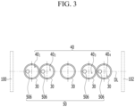
- FIG. 3 is a schematic view illustrating a positional relationship between the first nozzle 40 and the suction part 50 with respect to the imaginary straight line DL.
- the suction part 50 is shown based on the outlet 506.
- the imaginary straight line DL may be set to pass through the center of the entrance 100 and the center of the exit 102 of the main body 10 and to further pass through a center of the carrier 30.
- the four first nozzles 40 1 , 40 2 , 40 3 , and 40 4 are disposed with their centers staggered.
- a line connecting the four first nozzles 40 1 , 40 2 , 40 3 , and 40 4 may be disposed to be deviated from the straight line DL so that a shape of the line connecting the four first nozzles is approximately meandering.
- the four first nozzles may be respectively positioned at an upper side of the carrier 30 so as to spray (or inject) air toward circumference of the carrier 30 or toward the inside of the carrier 30.
- the suction part 50 is disposed close to each of the four first nozzles 40 1 , 40 2 , 40 3 , and 40 4 corresponding one-to-one, and sucks a foreign material separated from the carrier 30 by air sprayed from the four first nozzles 40 1 , 40 2 , 40 3 , and 40 4 .
- the suction part 50 may be positioned at an upper side of the carrier 30 so that the outlet 506 of the suction part 50 is positioned inside the carrier 30.
- the second nozzle 42 spraying a cleaning material (that is, dry ice) different from a cleaning material of the first nozzle 40 is disposed
- the second nozzle 42 may be connected to a dry ice supplier (not shown), and may be detachably coupled to an extension part 112 extending from an upper surface of the main body 10.
- the second nozzle 42 may be coupled to the upper surface of the extension part 112 through screw coupling.
- the second nozzle 42 may be fixed to the extension part 112, and the extension part 112 may be provided in a configuration in which the extension part 112 is detachably coupled to the upper surface of the main body 10.
- a third nozzle 80 for spraying air may be installed at an outer side of the main body 10 around at least one of the entrance 100 and the exit 102 of the main body 10.
- the third nozzle 80 is installed around both the entrance 100 and the exit 102.
- the third nozzle 80 may be provided as a so-called air knife installed at an angle (approximately 5 degrees) with respect to the main body 10 so as to spray air toward the inside of the main body 10.
- the third nozzle 80 may also be connected to the blowing manifold 60 by a hose (not shown) to spray air into the main body 10 so that the third nozzle prevents a foreign material from scattering from the outside to the inside of the main body 10.
- the cleaning apparatus 1 configured as described above may separate and clean a foreign material accumulated in the carrier 30 by air sprayed from the first nozzle 40 and dry ice sprayed from the second nozzle 42.
- the plurality of first nozzles 40 may spray air to various portions of the carrier 30 instead of one portion, and the second nozzle 42 may spray dry ice so that the carrier 30 is cleaned.
- the second nozzle 42 may spray dry ice so that the carrier 30 is cleaned.
Landscapes
- Engineering & Computer Science (AREA)
- Manufacturing & Machinery (AREA)
- Chemical & Material Sciences (AREA)
- Chemical Kinetics & Catalysis (AREA)
- Electrochemistry (AREA)
- General Chemical & Material Sciences (AREA)
- Mechanical Engineering (AREA)
- Cleaning In General (AREA)
- Cleaning By Liquid Or Steam (AREA)
- Battery Mounting, Suspending (AREA)
Abstract
Description
- This application claims priority to and the benefit of
Korean Patent Application No. 10-2021-0133814 filed in the Korean Intellectual Property Office on October 8, 2021 - The present invention relates to a cleaning apparatus, and more particularly, to an apparatus for cleaning a carrier used in an assembly line of a secondary battery.
- In general, a secondary battery (or a rechargeable battery) has a configuration in which an electrode assembly including a positive electrode, a negative electrode, and a separator interposed between the positive electrode and the negative electrode is accommodated in a case that is a can or a pouch.
- When the secondary battery is assembled, the electrode assembly or the case in which the electrode assembly is accommodated is transported to a required process line while being contained in a carrier.
- In order to produce a high-quality secondary battery, impurities should not be introduced into a component of the electrode assembly or the case. Accordingly, it is essential to maintain a clean state of a carrier used when the secondary battery is assembled.
- An object to be solved by the present invention is to improve cleaning of a foreign material accumulated in a carrier used for assembling a secondary battery.
- However, the problem to be solved by embodiments of the present invention is not limited to the above-described problem, and may be variously expanded in the range of the technical ideas included in the present invention.
- A cleaning apparatus of a carrier for a secondary battery that cleans the carrier transported by a transfer part according to an embodiment of the present invention includes: a main body that includes an entrance through which the transfer part enters and an exit through which the transfer part exits; and a plurality of nozzles installed at the main body to spray a cleaning material cleaning the carrier at the carrier. The plurality of nozzles include: a plurality of first nozzles disposed with their respective centers staggered with respect to an imaginary straight line along a direction from the entrance to the exit; and at least one second nozzle spraying a different cleaning material from a cleaning material sprayed from the plurality of first nozzles.
- The plurality of first nozzles may spray air, and the at least one second nozzle may spray dry ice.
- The plurality of first nozzles and the at least one second nozzle may be spaced apart from each other at an upper portion of the main body.
- The at least one second nozzle may be disposed at a center of the main body.
- A suction part may be disposed adjacent to each of the plurality of first nozzles.
- The suction part may be a truncated cone.
- The at least one second nozzle may be detachably installed at the main body.
- A third nozzle spraying air around at least one of the entrance and the exit may be installed at the main body.
- The third nozzle may be obliquely installed at the main body to spray air toward the inside of the main body.
- The secondary battery may be a cylindrical secondary battery.
- A cleaning apparatus of a carrier for a secondary battery according to an embodiment may satisfactorily remove a foreign material adhering to the carrier and may prevent the foreign material from accumulating on the carrier.
- Accordingly, when the secondary battery using the carrier according to the present invention is manufactured, inflow of the foreign material into a component of the secondary battery may be prevented in advance so that a high-quality secondary battery is manufactured.
- Effects of the present invention are not limited to the foregoing effects, and other non-mentioned effects will be clearly understood by those skilled in the art from the description below.
-
-
FIG. 1 is a plan view of a cleaning apparatus of a carrier for a secondary battery according to an embodiment of the present invention. -
FIG. 2 is a cross-sectional view taken along line II-II ofFIG. 1 . -
FIG. 3 is a schematic view illustrating a positional relationship between a first nozzle and a suction part with respect to an imaginary straight line according to an embodiment of the present invention. - The present invention will be described more fully hereinafter with reference to the accompanying drawings, in which exemplary embodiments of the invention are shown. As those skilled in the art would realize, the described embodiments may be modified in various different ways, all without departing from the spirit or scope of the present invention.
- Parts that are irrelevant to the description are omitted in the drawings for clear description of the present invention, and like reference numerals designate like elements throughout the specification.
- Further, the size and thickness of the elements shown in the drawings are arbitrarily illustrated for better understanding and ease of description, and the present invention is not necessarily limited thereto. In the drawings, the thicknesses of layers, films, panels, regions, etc., are exaggerated for clarity. In the drawings, for convenience of description, the thickness of layers, films, panels, areas, etc., are exaggerated.
- It will be understood that when an element such as a layer, film, region, or substrate is referred to as being "on" another element, it can be directly on the other element or intervening elements may also be present. In contrast, when an element is referred to as being "directly on" another element, there are no intervening elements present. Further, in the specification, the word "on" or "above" means positioned on or below the object portion, and does not necessarily mean positioned on the upper side of the object portion based on a gravitational direction.
- In addition, unless explicitly described to the contrary, the word "comprise", and variations such as "comprises" or "comprising", will be understood to imply the inclusion of stated elements but not the exclusion of any other elements.
- Further, throughout the specification, the phrase "on a plane" means viewing a target portion from the top, and the phrase "on a cross-section" means viewing a cross-section formed by vertically cutting a target portion from the side.
-
FIG. 1 is a plan view illustrating a cleaning apparatus of a carrier for a secondary battery (hereinafter referred to as the cleaning apparatus for convenience) according to an embodiment of the present invention, andFIG. 2 is a cross-sectional view taken along line II-II ofFIG. 1 . - As shown in
FIGS. 1 and2 , the cleaning apparatus 1 according to the embodiment includes amain body 10 having an inner space. Themain body 10 is provided in a substantially square box shape (or a substantially rectangular parallelepiped shape) and has an entrance (or an inlet) 100 and an exit (or an outlet) 102 provided at opposite sides (both left and right sides in the drawings). Due to this, themain body 10 may have a tunnel-type outer appearance. - The cleaning apparatus 1 according to the embodiment is configured to clean the
carrier 30 transported by atransfer part 20 that enters themain body 10 through theentrance 100 and advances to the outside of themain body 10 through theexit 102. - In the present embodiment, the
transfer part 20 may be formed of aconveyor belt 200, and thecarrier 30 may be provided for a cylindrical secondary battery (or a cylindrical rechargeable battery). Theconveyor belt 200 may be driven by a driving source (not shown) so that the conveyor belt is transported from the outside (left side based on the drawings) of themain body 10 to the outside (right side based on the drawings) of themain body 10 through the inside of themain body 10, and thecarrier 30 may be made with a cylindrical shape with one or both sides open while having an internal space in accordance with an outer shape of an electrode assembly or a case of the cylindrical secondary battery. However, in the present invention, thetransfer part 20 and thecarrier 30 are not necessarily limited to these. - A foreign material generated due to self-wear of the
carrier 30, friction between the carriers, or friction between the carrier and another component may be accumulated in the carrier. If the foreign material is continuously accumulated in thecarrier 30, there is a high probability that the foreign material will flow into the electrode assembly or the case accommodated in thecarrier 30 and will adversely affect the secondary battery to be manufactured. Thus, thecarrier 30 needs to be kept as clean as possible. - To this end, a plurality of nozzles for cleaning the foreign material that may accumulate in the
carrier 30 are installed in themain body 10. In the present embodiment, the plurality of nozzles are installed at distances at an upper surface of themain body 10 and are configured to spray a cleaning material from above thecarrier 30 toward thecarrier 30. - The plurality of nozzles include a plurality of
first nozzles 40 that spray air and at least onesecond nozzle 42 that sprays dry ice. For example, in the present embodiment, fourfirst nozzles 40 may be provided and onesecond nozzle 42 may be provided. - A first
first nozzle 401 and a fourthfirst nozzle 404 among the fourfirst nozzles 40 may be respectively installed at a predetermined distance d1 from theentrance 100 and theexit 102. The distance d1 may be set to sufficiently create an inner space of themain body 10 corresponding to a distance from theentrance 100 to the firstfirst nozzle 401 and a distance from theexit 102 to the fourthfirst nozzle 404. For example, the distance d1 may be set so that the foreign material that may be made inside themain body 10 does not accumulate in thecarrier 30. - In addition, a distance d2 between the first
first nozzle 401 and a secondfirst nozzle 402 among the fourfirst nozzles 40, and a distance d2 between a third first nozzle 40s and the fourthfirst nozzle 404 among the fourfirst nozzles 40, may be set equal to an outer diameter D of thecarrier 30. - Each of the four
first nozzles 40 is connected to abracket 44, and is fixedly installed at an upper surface of themain body 10. In addition, the fourfirst nozzles 40 are divided and connected to a plurality ofsuction parts 50 fixed at the upper surface of themain body 10. In the present embodiment, the firstfirst nozzle 401 and the secondfirst nozzle 402 are respectively inserted in athrough hole 502 of abracket 500 at which a pair offirst suction parts 501 are formed so that spray holes of the firstfirst nozzle 401 and the secondfirst nozzle 402 are disposed to be positioned as close as possible around thecarrier 30. In this case, a distance between the spray hole and thecarrier 30 may be several mm. On the other hand, the third first nozzle 40s and the fourthfirst nozzle 404 are respectively inserted in the throughhole 502 of thebracket 500 at which a pair ofsecond suction parts 502 are formed so that spray holes of the third first nozzle 40s and the fourthfirst nozzle 404 are also disposed to be positioned as close as possible around thecarrier 30. The fourfirst nozzles manifold 60 disposed at one side of themain body 10 by a hose (not shown). - Each of the
first suction part 501 and thesecond suction part 502 includes an inlet (or a suction port) 504 facing thecarrier 30 and anoutlet 506 disposed opposite to thesuction port 504. Here, a center of theinlet 504 and a center of theoutlet 506 may coincide. A shape of each of thefirst suction part 501 and thesecond suction part 502 may be formed in a shape of a truncated cone whose diameter decreases from theinlet 504 toward theoutlet 506 to improve suction efficiency. Thefirst suction part 501 and thesecond suction part 502 respectively correspond to adjacentfirst nozzles 40. Thebracket 500 of thefirst suction part 501 or thebracket 500 of thesecond suction part 502 may be fixedly coupled to an upper surface of themain body 10 by screw coupling, and aconnector 508 extending from theoutlet 506 and exposed to the outside of the upper surface of themain body 10 may be connected to asuction manifold 70 disposed at one side of themain body 10 by a hose (not shown). - When the four
first nozzles 40 are disposed at an upper surface of themain body 10, the fourfirst nozzles 40 are disposed with their respective centers staggered with respect to an imaginary straight line DL (e.g., the imaginary straight line DL (seeFIG. 1 ) passing through a center of theentrance 100 and a center of the exit 102) along a direction from theentrance 100 to theexit 102 of themain body 10 or an opposite direction thereof. -
FIG. 3 is a schematic view illustrating a positional relationship between thefirst nozzle 40 and thesuction part 50 with respect to the imaginary straight line DL. Here, thesuction part 50 is shown based on theoutlet 506. - As shown in
FIG. 3 , the imaginary straight line DL may be set to pass through the center of theentrance 100 and the center of theexit 102 of themain body 10 and to further pass through a center of thecarrier 30. With respect to the straight line DL, the fourfirst nozzles first nozzles carrier 30 so as to spray (or inject) air toward circumference of thecarrier 30 or toward the inside of thecarrier 30. - On the other hand, the
suction part 50 is disposed close to each of the fourfirst nozzles carrier 30 by air sprayed from the fourfirst nozzles suction part 50 may be positioned at an upper side of thecarrier 30 so that theoutlet 506 of thesuction part 50 is positioned inside thecarrier 30. - On the one hand, at a center of the
main body 10 between thefirst suction part 501 and thesecond suction part 502, thesecond nozzle 42 spraying a cleaning material (that is, dry ice) different from a cleaning material of thefirst nozzle 40 is disposed - In the present embodiment, the
second nozzle 42 may be connected to a dry ice supplier (not shown), and may be detachably coupled to anextension part 112 extending from an upper surface of themain body 10. For example, thesecond nozzle 42 may be coupled to the upper surface of theextension part 112 through screw coupling. In another embodiment, thesecond nozzle 42 may be fixed to theextension part 112, and theextension part 112 may be provided in a configuration in which theextension part 112 is detachably coupled to the upper surface of themain body 10. - On the one hand, a
third nozzle 80 for spraying air may be installed at an outer side of themain body 10 around at least one of theentrance 100 and theexit 102 of themain body 10. In the present embodiment, thethird nozzle 80 is installed around both theentrance 100 and theexit 102. In addition, thethird nozzle 80 may be provided as a so-called air knife installed at an angle (approximately 5 degrees) with respect to themain body 10 so as to spray air toward the inside of themain body 10. Thethird nozzle 80 may also be connected to the blowingmanifold 60 by a hose (not shown) to spray air into themain body 10 so that the third nozzle prevents a foreign material from scattering from the outside to the inside of themain body 10. - When the
carrier 30 required for manufacturing a secondary battery is transferred along theconveyor belt 200 into themain body 10, the cleaning apparatus 1 configured as described above may separate and clean a foreign material accumulated in thecarrier 30 by air sprayed from thefirst nozzle 40 and dry ice sprayed from thesecond nozzle 42. - In the cleaning apparatus 1 according to the present embodiment, the plurality of
first nozzles 40 may spray air to various portions of thecarrier 30 instead of one portion, and thesecond nozzle 42 may spray dry ice so that thecarrier 30 is cleaned. Thus, it is possible to effectively clean a foreign material adhering to thecarrier 30, and furthermore, it is possible to prevent the foreign material from accumulating in thecarrier 30. - While this invention has been described in connection with what is presently considered to be practical embodiments, it is to be understood that the invention is not limited to the disclosed embodiments. On the contrary, it is intended to cover various modifications and equivalent arrangements included within the spirit and scope of the appended claims.
-
- 1: cleaning apparatus
- 10: main body
- 20: transfer part
- 30: carrier
- 40: first nozzle
- 42: second nozzle
- 50: suction part
- 100: entrance
- 102: exit
Claims (10)
- A cleaning apparatus of a carrier for a secondary battery that cleans the carrier transported by a transfer part, comprising:a main body that includes an entrance through which the transfer part enters and an exit through which the transfer part exits; anda plurality of nozzles installed at the main body to spray a cleaning material cleaning the carrier at the carrier,wherein the plurality of nozzles comprise:a plurality of first nozzles disposed with their respective centers staggered with respect to an imaginary straight line along a direction from the entrance to the exit; andat least one second nozzle spraying a cleaning material different from a cleaning material sprayed from the plurality of first nozzles.
- The cleaning apparatus of claim 1, wherein the plurality of first nozzles spray air, and the at least one second nozzle sprays dry ice.
- The cleaning apparatus of claim 1 or claim 2, wherein the plurality of first nozzles and the at least one second nozzle are spaced apart from each other at an upper portion of the main body.
- The cleaning apparatus of claim 3, wherein the at least one second nozzle is disposed at a center of the main body.
- The cleaning apparatus of claim 1, wherein a suction part is disposed adjacent to each of the plurality of first nozzles.
- The cleaning apparatus of claim 5, wherein the suction part is a truncated cone.
- The cleaning apparatus of claim 1, wherein the at least one second nozzle is detachably installed at the main body.
- The cleaning apparatus of claim 1, wherein a third nozzle spraying air around at least one of the entrance and the exit is installed at the main body.
- The cleaning apparatus of claim 8, wherein the third nozzle is obliquely installed at the main body to spray air toward the inside of the main body.
- The cleaning apparatus of claim 1, wherein the secondary battery is a cylindrical secondary battery.
Applications Claiming Priority (2)
| Application Number | Priority Date | Filing Date | Title |
|---|---|---|---|
| KR1020210133814A KR20230050675A (en) | 2021-10-08 | 2021-10-08 | Cleaning appratus of carrier for rechargeble battery |
| PCT/KR2022/015210 WO2023059158A1 (en) | 2021-10-08 | 2022-10-07 | Cleaning device for secondary battery carrier |
Publications (2)
| Publication Number | Publication Date |
|---|---|
| EP4368303A1 true EP4368303A1 (en) | 2024-05-15 |
| EP4368303A4 EP4368303A4 (en) | 2025-05-14 |
Family
ID=85803640
Family Applications (1)
| Application Number | Title | Priority Date | Filing Date |
|---|---|---|---|
| EP22878979.8A Pending EP4368303A4 (en) | 2021-10-08 | 2022-10-07 | Cleaning device for secondary battery carrier |
Country Status (6)
| Country | Link |
|---|---|
| US (1) | US20240335864A1 (en) |
| EP (1) | EP4368303A4 (en) |
| JP (1) | JP7667370B2 (en) |
| KR (1) | KR20230050675A (en) |
| CN (1) | CN117794654A (en) |
| WO (1) | WO2023059158A1 (en) |
Family Cites Families (14)
| Publication number | Priority date | Publication date | Assignee | Title |
|---|---|---|---|---|
| JP2004335838A (en) * | 2003-05-09 | 2004-11-25 | Shin Etsu Handotai Co Ltd | Cleaning device, cleaning system and cleaning method |
| JP2006013339A (en) * | 2004-06-29 | 2006-01-12 | Dainippon Screen Mfg Co Ltd | Substrate cleaning equipment |
| KR100719164B1 (en) * | 2005-05-04 | 2007-05-17 | 에이비앤씨코리아(주) | Construction Gravel Washing Equipment |
| FR2950683B1 (en) * | 2009-09-25 | 2012-06-08 | Cims | COOLING INSTALLATION OF PRODUCTS COMPRISING A TUNNEL THROUGH WHICH THE PRODUCTS ARE MOVED TO SCROLL, A COLD AIR CURTAIN BEING GENERATED IN THE ENTRANCE OF THE TUNNEL |
| JP5889537B2 (en) * | 2011-03-23 | 2016-03-22 | ファスフォードテクノロジ株式会社 | Die bonder |
| DE102012006567A1 (en) * | 2012-03-30 | 2013-10-02 | Dürr Systems GmbH | Dry ice cleaning device for a paint shop |
| KR101531653B1 (en) * | 2013-07-16 | 2015-06-25 | 제이케이엔지니어링주식회사 | Tunnel Type Cleaning Apparatus for Container |
| KR101773667B1 (en) * | 2014-07-01 | 2017-08-31 | (주)태화기업 | Cleaning system for battery can |
| CN206444995U (en) * | 2017-01-13 | 2017-08-29 | 大唐南京环保科技有限责任公司 | A kind of creme piece-rate system of discarded plate-type denitration catalyst |
| CN207426008U (en) * | 2017-09-14 | 2018-05-29 | 深圳市东汇精密机电有限公司 | Full-automatic lithium battery liquid-filling machine for battery |
| CN209049774U (en) * | 2018-09-13 | 2019-07-02 | 南京元稀世特自动化设备有限公司 | Battery tray cleaning device |
| CN113030694B (en) * | 2021-01-06 | 2023-02-28 | 苏州凌创电子系统有限公司 | Floating testing device for multiple groups of PCB (printed circuit board) |
| CN113118141B (en) * | 2021-05-08 | 2025-07-01 | 摩比天线技术(深圳)有限公司 | Multi-nozzle dry ice cleaning device and method |
| CN113210358A (en) * | 2021-05-14 | 2021-08-06 | 摩比天线技术(深圳)有限公司 | Dry ice cleaning equipment |
-
2021
- 2021-10-08 KR KR1020210133814A patent/KR20230050675A/en active Pending
-
2022
- 2022-10-07 US US18/291,424 patent/US20240335864A1/en active Pending
- 2022-10-07 JP JP2024504850A patent/JP7667370B2/en active Active
- 2022-10-07 CN CN202280054510.XA patent/CN117794654A/en active Pending
- 2022-10-07 EP EP22878979.8A patent/EP4368303A4/en active Pending
- 2022-10-07 WO PCT/KR2022/015210 patent/WO2023059158A1/en not_active Ceased
Also Published As
| Publication number | Publication date |
|---|---|
| JP2024527944A (en) | 2024-07-26 |
| JP7667370B2 (en) | 2025-04-22 |
| WO2023059158A1 (en) | 2023-04-13 |
| CN117794654A (en) | 2024-03-29 |
| US20240335864A1 (en) | 2024-10-10 |
| EP4368303A4 (en) | 2025-05-14 |
| KR20230050675A (en) | 2023-04-17 |
Similar Documents
| Publication | Publication Date | Title |
|---|---|---|
| KR100941842B1 (en) | Air curtain forming device in mini-environment semiconductor manufacturing device | |
| TWI573637B (en) | Cleaning head | |
| ITTO20010068A1 (en) | QUICK RELEASE NOZZLE GROUP. | |
| CN101670215A (en) | A segregator that separates liquid vapor mixture and a cardinal plate processing equipment containing the segregator | |
| US20120292410A1 (en) | Nozzle assembly for spray apparatus | |
| US20210204492A1 (en) | Emitter and drip irrigation tube | |
| US20240335864A1 (en) | Cleaning Apparatus of Carrier for Secondary Battery | |
| CN101808710B (en) | Circular type air injection nozzles having two circular slits and filter cleaning system using them | |
| CN100377297C (en) | Substrate processing device | |
| US12036570B2 (en) | Filter module for coating equipment | |
| TWI503269B (en) | Swirling flow forming body and non-contact conveying device | |
| TWI564231B (en) | Air Float Handling Device and Air Floating Handling Method | |
| US9128278B2 (en) | Dust cleaning device | |
| JP4663919B2 (en) | Substrate dryer | |
| JP4523792B2 (en) | Mini-environment semiconductor manufacturing equipment | |
| KR101763452B1 (en) | Apparatus For Removing Foreign Matter From Transfer JIG | |
| CN223458399U (en) | Vacuum coating equipment, vacuum coating system and solar cell production line | |
| CN215997755U (en) | Injection mechanism and cleaning equipment | |
| CN118900720B (en) | Filtration membrane unit, holder for holding the filtration membrane unit, filtration system including filtration membrane unit and holder, and filtration treatment equipment including a plurality of filtration systems | |
| KR102961166B1 (en) | Cleaning apparatus | |
| TW201620618A (en) | Developer ejection nozzle and development processing device | |
| JP6451330B2 (en) | Parts supply device | |
| KR20180050251A (en) | METHOD AND APPARATUS FOR PRODUCING GLASS PLATE | |
| JP3809229B2 (en) | Equipment for removing contaminants such as water droplets and dust | |
| JP2021527950A (en) | Substrate transfer container and substrate transfer container stack |
Legal Events
| Date | Code | Title | Description |
|---|---|---|---|
| STAA | Information on the status of an ep patent application or granted ep patent |
Free format text: STATUS: THE INTERNATIONAL PUBLICATION HAS BEEN MADE |
|
| PUAI | Public reference made under article 153(3) epc to a published international application that has entered the european phase |
Free format text: ORIGINAL CODE: 0009012 |
|
| STAA | Information on the status of an ep patent application or granted ep patent |
Free format text: STATUS: REQUEST FOR EXAMINATION WAS MADE |
|
| 17P | Request for examination filed |
Effective date: 20240205 |
|
| AK | Designated contracting states |
Kind code of ref document: A1 Designated state(s): AL AT BE BG CH CY CZ DE DK EE ES FI FR GB GR HR HU IE IS IT LI LT LU LV MC ME MK MT NL NO PL PT RO RS SE SI SK SM TR |
|
| DAV | Request for validation of the european patent (deleted) | ||
| DAX | Request for extension of the european patent (deleted) | ||
| RIC1 | Information provided on ipc code assigned before grant |
Ipc: B24C 1/00 20060101ALI20241219BHEP Ipc: H01M 10/04 20060101ALI20241219BHEP Ipc: B08B 7/00 20060101ALI20241219BHEP Ipc: B08B 5/04 20060101ALI20241219BHEP Ipc: B08B 5/02 20060101AFI20241219BHEP |
|
| A4 | Supplementary search report drawn up and despatched |
Effective date: 20250414 |
|
| RIC1 | Information provided on ipc code assigned before grant |
Ipc: B24C 3/12 20060101ALI20250408BHEP Ipc: B24C 1/00 20060101ALI20250408BHEP Ipc: H01M 10/04 20060101ALI20250408BHEP Ipc: B08B 7/00 20060101ALI20250408BHEP Ipc: B08B 5/04 20060101ALI20250408BHEP Ipc: B08B 5/02 20060101AFI20250408BHEP |