EP4368255B1 - Kabelbaumverbinder - Google Patents
Kabelbaumverbinder Download PDFInfo
- Publication number
- EP4368255B1 EP4368255B1 EP24167216.1A EP24167216A EP4368255B1 EP 4368255 B1 EP4368255 B1 EP 4368255B1 EP 24167216 A EP24167216 A EP 24167216A EP 4368255 B1 EP4368255 B1 EP 4368255B1
- Authority
- EP
- European Patent Office
- Prior art keywords
- plate
- rib
- strap
- safety apparatus
- connector
- Prior art date
- Legal status (The legal status is an assumption and is not a legal conclusion. Google has not performed a legal analysis and makes no representation as to the accuracy of the status listed.)
- Active
Links
Images


Classifications
-
- A—HUMAN NECESSITIES
- A62—LIFE-SAVING; FIRE-FIGHTING
- A62B—DEVICES, APPARATUS OR METHODS FOR LIFE-SAVING
- A62B35/00—Safety belts or body harnesses; Similar equipment for limiting displacement of the human body, especially in case of sudden changes of motion
- A62B35/0006—Harnesses; Accessories therefor
- A62B35/0025—Details and accessories
- A62B35/0037—Attachments for lifelines and lanyards
-
- A—HUMAN NECESSITIES
- A44—HABERDASHERY; JEWELLERY
- A44B—BUTTONS, PINS, BUCKLES, SLIDE FASTENERS, OR THE LIKE
- A44B11/00—Buckles; Similar fasteners for interconnecting straps or the like, e.g. for safety belts
- A44B11/02—Buckles; Similar fasteners for interconnecting straps or the like, e.g. for safety belts frictionally engaging surface of straps
-
- A—HUMAN NECESSITIES
- A62—LIFE-SAVING; FIRE-FIGHTING
- A62B—DEVICES, APPARATUS OR METHODS FOR LIFE-SAVING
- A62B35/00—Safety belts or body harnesses; Similar equipment for limiting displacement of the human body, especially in case of sudden changes of motion
- A62B35/0006—Harnesses; Accessories therefor
- A62B35/0018—Full body harnesses covering at least shoulders and thighs
-
- A—HUMAN NECESSITIES
- A62—LIFE-SAVING; FIRE-FIGHTING
- A62B—DEVICES, APPARATUS OR METHODS FOR LIFE-SAVING
- A62B35/00—Safety belts or body harnesses; Similar equipment for limiting displacement of the human body, especially in case of sudden changes of motion
- A62B35/0006—Harnesses; Accessories therefor
- A62B35/0025—Details and accessories
- A62B35/0031—Belt sorting accessories, e.g. devices keeping the belts in comfortable positions
Definitions
- An example embodiment relates generally to safety harness, and particularly full body harness, worn by first responders and other users who work on platforms situated at a height and or like.
- Safety harness are commonly used as part of a fall protection system for persons subjected to the potential of a fall from a height.
- full-body safety harnesses are required when working on platforms that are at a height of six feet or greater.
- Such harnesses which typically include both an upper torso portion (having, for example, shoulder straps) and a lower torso or seat portion (having, for example one or more leg straps and sometimes a seat strap), can be designed in many alternative manners.
- the workers While working on such platforms or in such an environment, the workers may be required to move around, stand, squat or lean and with such actions the harness can become stiff and/or offer resistance to the movement. At times, the workers may feel uncomfortable while performing their daily activities in such a safety harness.
- WO 2016/175663 A1 discloses a strap buckle for a safety harness.
- a safety apparatus includes a full body harness and a connector attached to the full body harness to enable a mobility of a user wearing the full body harness.
- the connector includes a first plate defining a first plurality of slits, a second plate defining a second plurality of slits, and a fastener.
- the fastener facilitates a coupling of the first plate with the second plate, such that the first plate and the second plate are rotatable with respect to each other.
- the first plate includes a first plurality of slits to receive a first harness, and a second plurality of slits in the second plate is configured to receive a second harness that is separate from the first harness. Further, the first plate is identical to the second plate.
- a first surface of both, the first rib and the second rib define a downward slope towards distal ends of the first rib and the second rib from the first cavity and second cavity respectively.
- the plurality of arcuate portions on the first plate define a first channel and a second channel, such that the first channel and the second channel are configured to facilitate receiving of the first harness.
- the plurality of arcuate portions on the second plate define a third channel and a fourth channel, such that the third channel and the fourth channel are configured to facilitate receiving of the second harness.
- component or feature may,” “can,” “could,” “should,” “would,” “preferably,” “possibly,” “typically,” “optionally,” “for example,” “often,” or “might” (or other such language) be included or have a characteristic, that particular component or feature is not required to be included or to have the characteristic. Such component or feature may be optionally included in some embodiments, or it may be excluded.
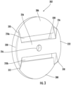
- FIG. 6 illustrates a schematic view of the connector 102 with harness.
- the connector 102 includes a first plate 202 and a second plate 204.
- the first shoulder strap 104 passes through the first plate 202
- the second shoulder strap passes through the second plate 204.
- the first plate 202 and the second plate 204 are coupled together by means of a fastener 206.
- the connector 102 facilitates the adjustment of the first shoulder strap 104 and the second shoulder strap 106.
- the connector enables the adjustment of an angle between the first shoulder strap 104 and the second shoulder strap 106 along a first direction 112 and the second direction 114, respectively.
- the first shoulder strap 104 includes a first webbing 608 and a second webbing 610
- the second shoulder strap 106 may have a third webbing 612 and a fourth webbing 614, where the connector 102 enables the adjustment of the angle 110 between the first webbing 608 and the third webbing 612, as illustrated in the FIG. 7 .
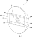
- FIG. 9b illustrates an example embodiment of the second plate 606 of the connector 602.
- the second plate 606 may be made from a metal, a polymeric material or an alloy.
- the second plate 606 may have any geometrical shape, such as a circular, oval, square or a rectangular shape.
Landscapes
- Health & Medical Sciences (AREA)
- General Health & Medical Sciences (AREA)
- Business, Economics & Management (AREA)
- Emergency Management (AREA)
- Emergency Lowering Means (AREA)
- Details Of Connecting Devices For Male And Female Coupling (AREA)
Claims (15)
- Sicherheitseinrichtung (100), umfassend:
einen Verbinder (102), der Verbinder umfassend:eine erste Platte (202), die eine erste Vielzahl von Schlitzen (210a, 210b) definiert;eine zweite Platte (204), die eine zweite Vielzahl von Schlitzen (212a, 212b) definiert; undein Befestigungselement (206), das eine Kopplung der ersten Platte mit der zweiten Platte ermöglicht, sodass die erste Platte und die zweite Platte in Bezug zueinander drehbar sind,eine erste Lasche (104),wobei die erste Lasche dazu konfiguriert ist, sich über die erste Vielzahl von Schlitzen zu bewegen; undeine zweite Lasche (106),wobei die zweite Lasche dazu konfiguriert ist, sich über die zweite Vielzahl von Schlitzen zu bewegen, wobei die erste Lasche von der zweiten Lasche verschieden ist,wobei jede von der ersten Platte (202) und der zweiten Platte (204) eine Vielzahl von gekrümmten Abschnitten in Randregionen der betroffenen Platte (202, 204) umfasst,wobei die Vielzahl von gekrümmten Abschnitten (220, 222) auf der ersten Platte (202) einen ersten Kanal (306) und einen zweiten Kanal (308) definiert, sodass der erste Kanal (306) und der zweite Kanal (308) dazu konfiguriert sind, das Aufnehmen der ersten Lasche zu ermöglichen, undwobei die Vielzahl von gekrümmten Abschnitten (224, 226) auf der zweiten Platte (204) einen dritten Kanal und einen vierten Kanal definiert, sodass der dritte Kanal und der vierte Kanal dazu konfiguriert sind, das Aufnehmen der zweiten Lasche zu ermöglichen. - Sicherheitseinrichtung nach Anspruch 1, wobei die erste Platte eine erste Rippe umfasst, sodass die erste Rippe sich diametral zwischen der Vielzahl von gekrümmten Abschnitten der ersten Platte erstreckt, und wobei die zweite Platte eine zweite Rippe umfasst, sodass die zweite Rippe sich zwischen der Vielzahl von gekrümmten Abschnitten der zweiten Platte erstreckt.
- Sicherheitseinrichtung nach Anspruch 2, wobei die erste Rippe und die zweite Rippe einen ersten Hohlraum bzw. einen zweiten Hohlraum definieren, wobei der erste Hohlraum und der zweite Hohlraum dazu konfiguriert sind, das Befestigungselement aufzunehmen.
- Sicherheitseinrichtung nach Anspruch 3, wobei eine erste Fläche der ersten Rippe und der zweiten Rippe ein absteigendes Gefälle in Richtung eines distalen Endes der ersten Rippe und der zweiten Rippe von dem ersten Hohlraum bzw. dem zweiten Hohlraum aus definieren.
- Sicherheitseinrichtung nach einem der Ansprüche 1 bis 4, wobei eine Dicke jedes gekrümmten Abschnitts größer ist als eine Dicke der Randregion der jeweiligen Platte.
- Sicherheitseinrichtung nach einem der Ansprüche 2 bis 4, wobei eine zweite Rippenfläche der ersten Rippe von einer zweiten Fläche der ersten Platte entlang einer zentralen Achse versetzt ist.
- Sicherheitseinrichtung nach einem der Ansprüche 2 bis 4, wobei eine zweite Rippenfläche der zweiten Rippe von einer zweiten Fläche der zweiten Platte entlang einer zentralen Achse versetzt ist.
- Sicherheitseinrichtung nach einem der vorhergehenden Ansprüche, wobei der Verbinder dazu konfiguriert ist, einen Winkel zwischen der ersten Lasche und der zweiten Lasche entlang einer ersten Richtung bzw. einer zweiten Richtung anzupassen.
- Sicherheitseinrichtung nach einem der vorhergehenden Ansprüche, wobei die erste Lasche einen ersten Gurt und einen zweiten Gurt umfasst und die zweite Lasche einen dritten Gurt und einen vierten Gurt umfasst.
- Sicherheitseinrichtung nach Anspruch 9, wobei der Verbinder dazu konfiguriert ist, einen Winkel zwischen dem ersten Gurt und dem dritten Gurt anzupassen.
- Sicherheitseinrichtung nach einem der vorhergehenden Ansprüche, wobei die erste Platte identisch mit der zweiten Platte ist.
- Sicherheitseinrichtung nach einem der Ansprüche 2 bis 11, wobei die erste Vielzahl von Schlitzen einen ersten Schlitz und einen zweiten Schlitz umfasst, die auf jeder Seite der ersten Rippe definiert sind.
- Sicherheitseinrichtung nach einem der Ansprüche 2 bis 12, wobei die zweite Vielzahl von Schlitzen einen dritten Schlitz und einen vierten Schlitz umfasst, die auf jeder Seite der zweiten Rippe angeordnet sind.
- Sicherheitseinrichtung nach einem der Ansprüche 3 bis 13, wobei der erste Hohlraum und der zweite Hohlraum eine zylindrische Form aufweisen.
- Sicherheitseinrichtung nach einem der Ansprüche 3 bis 14, wobei der erste Hohlraum und der zweite Hohlraum einen ringförmigen Wulst umfassen.
Applications Claiming Priority (2)
| Application Number | Priority Date | Filing Date | Title |
|---|---|---|---|
| CN202110360878.6A CN115177883A (zh) | 2021-04-02 | 2021-04-02 | 带具连接器 |
| EP21173518.8A EP4066905B1 (de) | 2021-04-02 | 2021-05-12 | Kabelbaumverbinder |
Related Parent Applications (2)
| Application Number | Title | Priority Date | Filing Date |
|---|---|---|---|
| EP21173518.8A Division-Into EP4066905B1 (de) | 2021-04-02 | 2021-05-12 | Kabelbaumverbinder |
| EP21173518.8A Division EP4066905B1 (de) | 2021-04-02 | 2021-05-12 | Kabelbaumverbinder |
Publications (4)
| Publication Number | Publication Date |
|---|---|
| EP4368255A2 EP4368255A2 (de) | 2024-05-15 |
| EP4368255A3 EP4368255A3 (de) | 2024-08-07 |
| EP4368255C0 EP4368255C0 (de) | 2025-07-09 |
| EP4368255B1 true EP4368255B1 (de) | 2025-07-09 |
Family
ID=75914372
Family Applications (2)
| Application Number | Title | Priority Date | Filing Date |
|---|---|---|---|
| EP24167216.1A Active EP4368255B1 (de) | 2021-04-02 | 2021-05-12 | Kabelbaumverbinder |
| EP21173518.8A Active EP4066905B1 (de) | 2021-04-02 | 2021-05-12 | Kabelbaumverbinder |
Family Applications After (1)
| Application Number | Title | Priority Date | Filing Date |
|---|---|---|---|
| EP21173518.8A Active EP4066905B1 (de) | 2021-04-02 | 2021-05-12 | Kabelbaumverbinder |
Country Status (3)
| Country | Link |
|---|---|
| US (3) | US11986684B2 (de) |
| EP (2) | EP4368255B1 (de) |
| CN (1) | CN115177883A (de) |
Families Citing this family (1)
| Publication number | Priority date | Publication date | Assignee | Title |
|---|---|---|---|---|
| USD1000712S1 (en) * | 2021-10-04 | 2023-10-03 | Stephen M. Richardson | Hunting saddle |
Family Cites Families (12)
| Publication number | Priority date | Publication date | Assignee | Title |
|---|---|---|---|---|
| US1437250A (en) | 1922-04-20 | 1922-11-28 | Alma Mfg Company | Sliding-tongue buckle |
| USD399172S (en) * | 1997-08-15 | 1998-10-06 | National Molding Corp. | Buckle |
| JP2003245106A (ja) * | 2002-02-25 | 2003-09-02 | Ykk Corp | ベルト止具 |
| USD507990S1 (en) * | 2003-08-08 | 2005-08-02 | Nifco Inc. | Buckle |
| WO2006017350A1 (en) * | 2004-07-12 | 2006-02-16 | Bacou-Dalloz Fall Protection, Inc. | Safety harnesses |
| GB2431336B (en) | 2005-10-21 | 2008-12-31 | Heightec Group Ltd | Suspension harness with adjustable attachment point |
| CA2663296C (en) | 2006-09-08 | 2015-10-20 | Sperian Fall Protection Inc. | Safety harnesses, connective ring attachments for use in safety harnesses and back pads for use in safety harnesses |
| JP4980871B2 (ja) * | 2007-12-19 | 2012-07-18 | ミドリ安全株式会社 | ベルト連結具及びこれを利用したハーネス型安全帯 |
| NO339972B1 (no) * | 2015-04-30 | 2017-02-27 | Moeller Sverre | Stroppspenne |
| FR3036037B1 (fr) | 2015-05-13 | 2017-05-26 | Zedel | Harnais d'encordement perfectionne |
| US10821310B2 (en) | 2017-09-07 | 2020-11-03 | Msa Technology, Llc | Harness with pivoting hip connection |
| US11191325B2 (en) | 2018-04-13 | 2021-12-07 | Msa Technology, Llc | Harness connection arrangement |
-
2021
- 2021-04-02 CN CN202110360878.6A patent/CN115177883A/zh active Pending
- 2021-05-12 EP EP24167216.1A patent/EP4368255B1/de active Active
- 2021-05-12 EP EP21173518.8A patent/EP4066905B1/de active Active
- 2021-05-14 US US17/302,878 patent/US11986684B2/en active Active
-
2024
- 2024-04-16 US US18/636,795 patent/US12329996B2/en active Active
-
2025
- 2025-05-22 US US19/215,963 patent/US20250345639A1/en active Pending
Also Published As
| Publication number | Publication date |
|---|---|
| US12329996B2 (en) | 2025-06-17 |
| EP4368255C0 (de) | 2025-07-09 |
| CN115177883A (zh) | 2022-10-14 |
| US11986684B2 (en) | 2024-05-21 |
| US20240252853A1 (en) | 2024-08-01 |
| US20250345639A1 (en) | 2025-11-13 |
| EP4066905B1 (de) | 2024-05-08 |
| EP4368255A3 (de) | 2024-08-07 |
| EP4066905A1 (de) | 2022-10-05 |
| US20220314043A1 (en) | 2022-10-06 |
| EP4368255A2 (de) | 2024-05-15 |
| EP4066905C0 (de) | 2024-05-08 |
Similar Documents
| Publication | Publication Date | Title |
|---|---|---|
| US20250345639A1 (en) | Harness connector | |
| CN106794367B (zh) | 安全带具 | |
| US5433289A (en) | Workers' Multi-functional harness | |
| US9248324B1 (en) | Swivel D-ring attachment point | |
| EP1545713B1 (de) | Ganzkörpersicherheitsharnas zum schutz vor stützen | |
| CN111225719B (zh) | 带有枢转髋部连接的保护带 | |
| US12053061B2 (en) | Buckle assembly and harness comprising the same | |
| EP3824956B1 (de) | Vorrichtungen zur bereitstellung von fallschutzsystemen | |
| US20230026773A1 (en) | Integrated personal protective equipment connector element for use with a wearable safety harness | |
| EP2525876B1 (de) | Fixierbare anordnung für gurtzeug | |
| US6527082B1 (en) | Attachment ring assembly for a safety harness and method of attaching an attachment ring to a safety harness | |
| KR20220140405A (ko) | 사용자의 편의성이 향상된 웨이트리프팅 벨트 | |
| US20230241430A1 (en) | Roping harness with ventral suspension point | |
| EP3034133B1 (de) | Sicherheitsgurt mit vertikal einstellbarem Gurt | |
| WO2020172695A1 (de) | Haltevorrichtung für die benutzung von gymnastikgeräten | |
| WO1999013947A1 (en) | Full body harness for fall arrest | |
| EP1803487B1 (de) | Sicherheitsgeschirr | |
| EP4272628B1 (de) | Körpertragesystem für eine mobile vorrichtung | |
| CN213341436U (zh) | 脚登式单双分裂导线走线工具专用后备保护装置 | |
| CA2549813C (en) | Convertible weightlifting belt | |
| DE202006018917U1 (de) | Tragevorrichtung |
Legal Events
| Date | Code | Title | Description |
|---|---|---|---|
| PUAI | Public reference made under article 153(3) epc to a published international application that has entered the european phase |
Free format text: ORIGINAL CODE: 0009012 |
|
| STAA | Information on the status of an ep patent application or granted ep patent |
Free format text: STATUS: THE APPLICATION HAS BEEN PUBLISHED |
|
| AC | Divisional application: reference to earlier application |
Ref document number: 4066905 Country of ref document: EP Kind code of ref document: P |
|
| AK | Designated contracting states |
Kind code of ref document: A2 Designated state(s): AL AT BE BG CH CY CZ DE DK EE ES FI FR GB GR HR HU IE IS IT LI LT LU LV MC MK MT NL NO PL PT RO RS SE SI SK SM TR |
|
| PUAL | Search report despatched |
Free format text: ORIGINAL CODE: 0009013 |
|
| AK | Designated contracting states |
Kind code of ref document: A3 Designated state(s): AL AT BE BG CH CY CZ DE DK EE ES FI FR GB GR HR HU IE IS IT LI LT LU LV MC MK MT NL NO PL PT RO RS SE SI SK SM TR |
|
| RIC1 | Information provided on ipc code assigned before grant |
Ipc: A62B 35/00 20060101AFI20240703BHEP |
|
| STAA | Information on the status of an ep patent application or granted ep patent |
Free format text: STATUS: REQUEST FOR EXAMINATION WAS MADE |
|
| 17P | Request for examination filed |
Effective date: 20241008 |
|
| RBV | Designated contracting states (corrected) |
Designated state(s): AL AT BE BG CH CY CZ DE DK EE ES FI FR GB GR HR HU IE IS IT LI LT LU LV MC MK MT NL NO PL PT RO RS SE SI SK SM TR |
|
| GRAP | Despatch of communication of intention to grant a patent |
Free format text: ORIGINAL CODE: EPIDOSNIGR1 |
|
| STAA | Information on the status of an ep patent application or granted ep patent |
Free format text: STATUS: GRANT OF PATENT IS INTENDED |
|
| INTG | Intention to grant announced |
Effective date: 20250203 |
|
| GRAS | Grant fee paid |
Free format text: ORIGINAL CODE: EPIDOSNIGR3 |
|
| GRAA | (expected) grant |
Free format text: ORIGINAL CODE: 0009210 |
|
| STAA | Information on the status of an ep patent application or granted ep patent |
Free format text: STATUS: THE PATENT HAS BEEN GRANTED |
|
| RAP1 | Party data changed (applicant data changed or rights of an application transferred) |
Owner name: HONEYWELL SAFETY PRODUCTS USA, INC. |
|
| AC | Divisional application: reference to earlier application |
Ref document number: 4066905 Country of ref document: EP Kind code of ref document: P |
|
| AK | Designated contracting states |
Kind code of ref document: B1 Designated state(s): AL AT BE BG CH CY CZ DE DK EE ES FI FR GB GR HR HU IE IS IT LI LT LU LV MC MK MT NL NO PL PT RO RS SE SI SK SM TR |
|
| REG | Reference to a national code |
Ref country code: GB Ref legal event code: FG4D |
|
| REG | Reference to a national code |
Ref country code: CH Ref legal event code: EP |
|
| REG | Reference to a national code |
Ref country code: IE Ref legal event code: FG4D |
|
| REG | Reference to a national code |
Ref country code: DE Ref legal event code: R096 Ref document number: 602021034022 Country of ref document: DE |
|
| U01 | Request for unitary effect filed |
Effective date: 20250804 |
|
| U07 | Unitary effect registered |
Designated state(s): AT BE BG DE DK EE FI FR IT LT LU LV MT NL PT RO SE SI Effective date: 20250813 |
|
| PG25 | Lapsed in a contracting state [announced via postgrant information from national office to epo] |
Ref country code: IS Free format text: LAPSE BECAUSE OF FAILURE TO SUBMIT A TRANSLATION OF THE DESCRIPTION OR TO PAY THE FEE WITHIN THE PRESCRIBED TIME-LIMIT Effective date: 20251109 |
|
| PG25 | Lapsed in a contracting state [announced via postgrant information from national office to epo] |
Ref country code: NO Free format text: LAPSE BECAUSE OF FAILURE TO SUBMIT A TRANSLATION OF THE DESCRIPTION OR TO PAY THE FEE WITHIN THE PRESCRIBED TIME-LIMIT Effective date: 20251009 |
|
| PG25 | Lapsed in a contracting state [announced via postgrant information from national office to epo] |
Ref country code: HR Free format text: LAPSE BECAUSE OF FAILURE TO SUBMIT A TRANSLATION OF THE DESCRIPTION OR TO PAY THE FEE WITHIN THE PRESCRIBED TIME-LIMIT Effective date: 20250709 |
|
| PG25 | Lapsed in a contracting state [announced via postgrant information from national office to epo] |
Ref country code: GR Free format text: LAPSE BECAUSE OF FAILURE TO SUBMIT A TRANSLATION OF THE DESCRIPTION OR TO PAY THE FEE WITHIN THE PRESCRIBED TIME-LIMIT Effective date: 20251010 |
|
| PG25 | Lapsed in a contracting state [announced via postgrant information from national office to epo] |
Ref country code: PL Free format text: LAPSE BECAUSE OF FAILURE TO SUBMIT A TRANSLATION OF THE DESCRIPTION OR TO PAY THE FEE WITHIN THE PRESCRIBED TIME-LIMIT Effective date: 20250709 |
|
| PG25 | Lapsed in a contracting state [announced via postgrant information from national office to epo] |
Ref country code: RS Free format text: LAPSE BECAUSE OF FAILURE TO SUBMIT A TRANSLATION OF THE DESCRIPTION OR TO PAY THE FEE WITHIN THE PRESCRIBED TIME-LIMIT Effective date: 20251009 |
|
| PG25 | Lapsed in a contracting state [announced via postgrant information from national office to epo] |
Ref country code: ES Free format text: LAPSE BECAUSE OF FAILURE TO SUBMIT A TRANSLATION OF THE DESCRIPTION OR TO PAY THE FEE WITHIN THE PRESCRIBED TIME-LIMIT Effective date: 20250709 |