EP4368255A2 - Kabelbaumverbinder - Google Patents
Kabelbaumverbinder Download PDFInfo
- Publication number
- EP4368255A2 EP4368255A2 EP24167216.1A EP24167216A EP4368255A2 EP 4368255 A2 EP4368255 A2 EP 4368255A2 EP 24167216 A EP24167216 A EP 24167216A EP 4368255 A2 EP4368255 A2 EP 4368255A2
- Authority
- EP
- European Patent Office
- Prior art keywords
- plate
- rib
- strap
- connector
- safety apparatus
- Prior art date
- Legal status (The legal status is an assumption and is not a legal conclusion. Google has not performed a legal analysis and makes no representation as to the accuracy of the status listed.)
- Granted
Links
Images


Classifications
-
- A—HUMAN NECESSITIES
- A62—LIFE-SAVING; FIRE-FIGHTING
- A62B—DEVICES, APPARATUS OR METHODS FOR LIFE-SAVING
- A62B35/00—Safety belts or body harnesses; Similar equipment for limiting displacement of the human body, especially in case of sudden changes of motion
- A62B35/0006—Harnesses; Accessories therefor
- A62B35/0025—Details and accessories
- A62B35/0037—Attachments for lifelines and lanyards
-
- A—HUMAN NECESSITIES
- A62—LIFE-SAVING; FIRE-FIGHTING
- A62B—DEVICES, APPARATUS OR METHODS FOR LIFE-SAVING
- A62B35/00—Safety belts or body harnesses; Similar equipment for limiting displacement of the human body, especially in case of sudden changes of motion
- A62B35/0006—Harnesses; Accessories therefor
- A62B35/0025—Details and accessories
- A62B35/0031—Belt sorting accessories, e.g. devices keeping the belts in comfortable positions
-
- A—HUMAN NECESSITIES
- A62—LIFE-SAVING; FIRE-FIGHTING
- A62B—DEVICES, APPARATUS OR METHODS FOR LIFE-SAVING
- A62B35/00—Safety belts or body harnesses; Similar equipment for limiting displacement of the human body, especially in case of sudden changes of motion
- A62B35/0006—Harnesses; Accessories therefor
- A62B35/0025—Details and accessories
-
- A—HUMAN NECESSITIES
- A44—HABERDASHERY; JEWELLERY
- A44B—BUTTONS, PINS, BUCKLES, SLIDE FASTENERS, OR THE LIKE
- A44B11/00—Buckles; Similar fasteners for interconnecting straps or the like, e.g. for safety belts
- A44B11/02—Buckles; Similar fasteners for interconnecting straps or the like, e.g. for safety belts frictionally engaging surface of straps
-
- A—HUMAN NECESSITIES
- A62—LIFE-SAVING; FIRE-FIGHTING
- A62B—DEVICES, APPARATUS OR METHODS FOR LIFE-SAVING
- A62B35/00—Safety belts or body harnesses; Similar equipment for limiting displacement of the human body, especially in case of sudden changes of motion
- A62B35/0006—Harnesses; Accessories therefor
- A62B35/0018—Full body harnesses covering at least shoulders and thighs
Definitions
- An example embodiment relates generally to safety harness, and particularly full body harness, worn by first responders and other users who work on platforms situated at a height and or like.
- Safety harness are commonly used as part of a fall protection system for persons subjected to the potential of a fall from a height.
- full-body safety harnesses are required when working on platforms that are at a height of six feet or greater.
- Such harnesses which typically include both an upper torso portion (having, for example, shoulder straps) and a lower torso or seat portion (having, for example one or more leg straps and sometimes a seat strap), can be designed in many alternative manners. While working on such platforms or in such an environment, the workers may be required to move around, stand, squat or lean and with such actions the harness can become stiff and/or offer resistance to the movement. At times, the workers may feel uncomfortable while performing their daily activities in such a safety harness.
- a safety apparatus includes a full body harness and a connector attached to the full body harness to enable a mobility of a user wearing the full body harness.
- the connector includes a first plate defining a first plurality of slits, a second plate defining a second plurality of slits, and a fastener.
- the fastener facilitates a coupling of the first plate with the second plate, such that the first plate and the second plate are rotatable with respect to each other.
- the first plate includes a first plurality of slits to receive a first harness, and a second plurality of slits in the second plate is configured to receive a second harness that is separate from the first harness. Further, the first plate is identical to the second plate.
- Implementations may include one or more of the following features.
- the connector where each of the first plate and the second plate may include a plurality of arcuate portions at a peripheral region of the first plate and the second plate.
- the first plate may include a first rib, such that the first rib extends diametrically between the plurality of arcuate portions of the first plate, and where the second plate may include a second rib, such that the second rib extends between the plurality of arcuate portions of the second plate.
- the first rib and the second rib define a first cavity and a second cavity respectively, where the first cavity and the second cavity are configured to receive the fastener.
- a first surface of both, the first rib and the second rib define a downward slope towards distal ends of the first rib and the second rib from the first cavity and second cavity respectively.
- the plurality of arcuate portions on the first plate define a first channel and a second channel, such that the first channel and the second channel are configured to facilitate receiving of the first harness.
- the plurality of arcuate portions on the second plate define a third channel and a fourth channel, such that the third channel and the fourth channel are configured to facilitate receiving of the second harness.
- component or feature may,” “can,” “could,” “should,” “would,” “preferably,” “possibly,” “typically,” “optionally,” “for example,” “often,” or “might” (or other such language) be included or have a characteristic, that particular component or feature is not required to be included or to have the characteristic. Such component or feature may be optionally included in some embodiments, or it may be excluded.
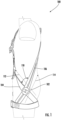
- FIG. 1 illustrates an embodiment of a safety apparatus 100 having a conventional, commercially available full-body harness.
- Safety harness 100 can include an upper torso portion comprising first shoulder strap 104 and a second shoulder strap 106, respectively, for extending over the shoulders of a user and a multi-component chest strap (not shown) for extending over and/or wrapping around the chest of the user.
- a first end of each of the first shoulder strap 104 and second shoulder strap 106 may extend down over the chest of the user and the back of the user and couple with each other by means of a connector 102 at a waist of the user.
- the first shoulder strap 104 and the second shoulder strap 106 can crisscross each other at the connector 102 and extend over to one or more leg straps.
- the connector 102 enables the adjustment of a length of the first shoulder strap 104 and second shoulder strap 106 when the user is performing different movements which may involve, walking, stretching, squatting, etc.
- the connector facilitates flexion and/or extension of the first shoulder strap 104 and the second shoulder strap 106.
- the connector 102 may be made either from a polymer, a metal or an alloy, and is capable of bearing the stress and strain associated with the forces acting through the first shoulder strap 104 and the second shoulder strap 106.
- the connector 102 can withstand the temperature variations occurring in the nature without deforming or breaking.
- the connector 102 may move in a first direction 112 of the first shoulder strap 104 or in a second direction 114 of the second shoulder strap 106 in order to accommodate users of various shapes and sizes. Further, the connector 102 may rotate in such a manner which enables a variation of an angle 110 between the first shoulder strap 104 and the second shoulder strap 106. Such movements can ease the working of the user and moreover, enables the harness to be worn by workers of different shapes, sizes, height, weight, etc.
- FIG. 2 illustrates an embodiment of the connector 102.
- the connector 102 can include a first plate 202, a second plate 204, and a fastener 206.
- the first plate 202 can be similar or even identical to the second plate 204. Both, the first plate 202 and the second plate 204 can have a first surface 232 and a second surface 234.
- the first plate 202 can include a first slit 210a and a second slit 210b, a first arcuate portion 220, a second arcuate portion 222, and a first rib 228.
- the first arcuate portion 220 and the second arcuate portion 222 can be integral to the first plate 202 and can be positioned on the periphery of the first plate 202.
- the first arcuate portion 220 and the second arcuate portion 222 are an extension of the first plate 202 over the first surface 232 along an axis parallel to a central axis 240. Further, the first arcuate portion 220 and the second arcuate portion 222 can be positioned opposite of each other.
- the second plate 204 may include a third slit 212a, a fourth slit 212b, a third arcuate portion 224, a fourth arcuate portion 226, and a second rib 230.
- a variation in the width of the slits enables an appropriate friction of the connector with the first shoulder strap 104 and/or the second shoulder strap 106.
- the fastener 206 may include a nut 206 and a bolt 208.
- the fastener 206 may be a screw or a rivet.
- the fastener 206 can facilitate a rotatable coupling of the first plate 202 to the second plate 204 such that the first plate 202 may freely rotate with respect to the second plate 204.
- the first plate 202 can be coupled to the second plate 204 such that the first surface 232 of the first plate 202 abuts the first surface 232 of the second plate 204.
- the first arcuate portion 220 and the second arcuate portion 222 can have a thickness greater than a thickness of a peripheral region of the first plate along the central axis 240 that is perpendicular to the first surface 232.
- the first rib 228 diametrically extends between the first arcuate portion 220 and the second arcuate portion 222. Further, the first slit 210a and the second slit 210b are defined on either side of the first rib 228.
- the first rib 228 defines a first cylindrical cavity 216 to facilitate an insertion of the fastener 206 into the first cylindrical cavity 216 along an axis parallel to the central axis 240 of the first cylindrical cavity 216.
- the first rib 228 includes a first rib surface 236 and a second rib surface 238.
- the first rib 228 is positioned in such a manner that the second rib surface 238 of the first rib 228 is offset from the second surface 234 of the first plate 202 along the central axis 240 of the first cylindrical cavity 216.
- the first slit 210a and second slit 210b are defined on either side of first rib 228. More specifically, the first slit 210a and the second slit 210b are defined between the first rib 228 and the peripheral regions of the first plate 202.
- the second rib 230 diametrically extends between the third arcuate portion 224 and the fourth arcuate portion 226.
- the second rib 230 defines a second cylindrical cavity 218 to facilitate an insertion of the fastener 206 into the second cylindrical cavity along an axis parallel to the central axis 241 of the second cylindrical cavity 218.
- the second rib 230 includes a third rib surface 242 and a fourth rib surface 244.
- the second rib 230 is positioned in such a manner that the fourth rib surface 244 of the second rib 230 is offset from the fourth surface 243 of the second plate 204 along the central axis 241 of the second cylindrical cavity 218.
- the third slit 212a and fourth slit 212b are defined on either side of the second rib 230. More specifically, the third slit 212a and the fourth slit 212b are defined between the second rib 230 and the peripheral regions of the second plate 204.
- the first plate 202 and the second plate 204 are coupled such that the first cylindrical cavity 216 of the first plate 202 overlaps the second cylindrical cavity 218 of the second plate 204 and both the cylindrical cavities have a common central axis.
- the fastener 206 may be inserted that enables the first plate 202 and the second plate 204 to be rotatably coupled.
- the connector enables a manual adjustment of position of the connector 102 on the first shoulder strap 104 and the second shoulder strap 106.
- the connector 102 by means of rotation of the first plate 202 and the second plate 204 with each other, enables a variation of the angle 110 between the first shoulder strap 104 and the second shoulder strap 106.
- FIG. 3 illustrates an example of the first surface 232 of the first plate 202.
- the first channel 306 is configured to receive a webbing.
- the second channel 308 is configured to receive a webbing.
- the first channel 306 is configured to receive the first shoulder strap 104 and facilitate a passage of the first shoulder strap 104 through the first slit 210a and over the second surface of the first rib 230. Thereafter, the first shoulder strap 104 may pass through the second slit 210b and over the second channel 308.
- FIG. 4 illustrates an embodiment of the second surface 234 of the first plate 202.
- the first rib 228 is positioned in such a manner that the second rib surface 238 of the first rib 228 is at an offset 402 from the second surface 234 of the first plate 202 along the central axis 240 of the first cylindrical cavity 216.
- the offset 402 allows an easy passage of the first shoulder strap 104 over the second surface of the first rib 228.
- the first rib 228 includes a counterbore 404 concentric to the first cylindrical cavity 216 defined on the first rib 228. The counterbore facilitates positioning of a nut or a head of the fastener 206.
- FIG. 5 illustrates a side view of the first plate 202.
- the first surface of the first rib 228 includes a first downward slope from the first cylindrical cavity 216 towards the first arcuate portion 220.
- the first surface of the first rib 228 includes a second downward slope from the first cylindrical cavity 216 towards the second arcuate portion 222.
- the first downward slope and the second downward slope reduce the friction between the first plate 202 and the second plate 204 when coupled together by means of a fastener 206.
- the first downward slope and the second downward slope create an offset.
- the first plate 202 may be coupled to the second plate 204 by the fastener 206. The offset enables a free rotation of the first plate 202 with respect to the second plate 204 along an axis defined by the fastener 206.
- FIG. 6 illustrates a schematic view of the connector 102 with harness.
- the connector 102 includes a first plate 202 and a second plate 204.
- the first shoulder strap 104 passes through the first plate 202
- the second shoulder strap passes through the second plate 204.
- the first plate 202 and the second plate 204 are coupled together by means of a fastener 206.
- the connector 102 facilitates the adjustment of the first shoulder strap 104 and the second shoulder strap 106.
- the connector enables the adjustment of an angle between the first shoulder strap 104 and the second shoulder strap 106 along a first direction 112 and the second direction 114, respectively.
- the first shoulder strap 104 includes a first webbing 608 and a second webbing 610
- the second shoulder strap 106 may have a third webbing 612 and a fourth webbing 614, where the connector 102 enables the adjustment of the angle 110 between the first webbing 608 and the third webbing 612, as illustrated in the FIG. 7 .
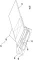
- FIG. 7 illustrates an alternate embodiment of a safety harness 600.
- Safety harness 600 includes a connector 602, a plurality of webbings including a first webbing 608, a second webbing 610, a third webbing 612, and a fourth webbing 614.
- the plurality of webbings are separate from each other.
- the connector 602 includes a first plate 604, a second plate 606, wherein the first plate 604 and the second plate 606 are rotatably coupled together by means of the connector 602.
- the connector 602 enables the adjustment of the angle between the plurality of webbings such that users of different shapes and sizes may wear and operate the harness with ease.
- the connector 602 is identical to the connector 102, with the only the difference being the geometrical shape.
- the connector 602 includes all the elements of the connector 102.
- the first webbing 608, the second webbing 610, the third webbing 612, and the fourth webbing 614 may be connected to separate slits of the first plate 602 and the second plate 604.
- Fig 8 illustrates a sectional view of the connector 602.
- the connector 602 includes a first plate 604, a second plate 606.
- the first plate 604 includes a first cylindrical cavity 702 configured to receive a fastener (not shown herein).
- the second plate 606 includes a second cylindrical cavity 704 configured to receive the fastener.
- the first plate 604 is rotatably coupled to the second plate 606 by means of the fastener (not shown herein) similar to the fastener 206 illustrated in the FIG. 2 .
- FIG. 9a illustrates an example embodiment of the first plate 604 of the connector 602.
- the first plate 604 may be made from a metal, a polymeric material or an alloy.
- the first plate 604 may have any geometrical shape, such as a circular, oval, square or a rectangular shape.
- FIG. 10 illustrates an example embodiment of the first plate 202 of the connector 102.
- the first channel 306 and the second channel 308 may be a slit at the peripheral region of the first plate 202, such that the slit is perpendicular to the central axis 240.
- the slit facilitates easy passage of the first shoulder strap 104 therethrough.
- the slit shape of the channel 306 and second channel 308 hinders development of any frictional resistance between the straps associated with the first plate 202 and the second plate 204 of the connector 102.
- the first cylindrical cavity 216 on the first rib 228 may include an annular bead. In some embodiments, the first rib 228 may not include any downward slope.
Landscapes
- Health & Medical Sciences (AREA)
- General Health & Medical Sciences (AREA)
- Business, Economics & Management (AREA)
- Emergency Management (AREA)
- Emergency Lowering Means (AREA)
- Details Of Connecting Devices For Male And Female Coupling (AREA)
Applications Claiming Priority (2)
| Application Number | Priority Date | Filing Date | Title |
|---|---|---|---|
| CN202110360878.6A CN115177883A (zh) | 2021-04-02 | 2021-04-02 | 带具连接器 |
| EP21173518.8A EP4066905B1 (de) | 2021-04-02 | 2021-05-12 | Kabelbaumverbinder |
Related Parent Applications (2)
| Application Number | Title | Priority Date | Filing Date |
|---|---|---|---|
| EP21173518.8A Division-Into EP4066905B1 (de) | 2021-04-02 | 2021-05-12 | Kabelbaumverbinder |
| EP21173518.8A Division EP4066905B1 (de) | 2021-04-02 | 2021-05-12 | Kabelbaumverbinder |
Publications (4)
| Publication Number | Publication Date |
|---|---|
| EP4368255A2 true EP4368255A2 (de) | 2024-05-15 |
| EP4368255A3 EP4368255A3 (de) | 2024-08-07 |
| EP4368255C0 EP4368255C0 (de) | 2025-07-09 |
| EP4368255B1 EP4368255B1 (de) | 2025-07-09 |
Family
ID=75914372
Family Applications (2)
| Application Number | Title | Priority Date | Filing Date |
|---|---|---|---|
| EP24167216.1A Active EP4368255B1 (de) | 2021-04-02 | 2021-05-12 | Kabelbaumverbinder |
| EP21173518.8A Active EP4066905B1 (de) | 2021-04-02 | 2021-05-12 | Kabelbaumverbinder |
Family Applications After (1)
| Application Number | Title | Priority Date | Filing Date |
|---|---|---|---|
| EP21173518.8A Active EP4066905B1 (de) | 2021-04-02 | 2021-05-12 | Kabelbaumverbinder |
Country Status (3)
| Country | Link |
|---|---|
| US (3) | US11986684B2 (de) |
| EP (2) | EP4368255B1 (de) |
| CN (1) | CN115177883A (de) |
Families Citing this family (1)
| Publication number | Priority date | Publication date | Assignee | Title |
|---|---|---|---|---|
| USD1000712S1 (en) * | 2021-10-04 | 2023-10-03 | Stephen M. Richardson | Hunting saddle |
Family Cites Families (12)
| Publication number | Priority date | Publication date | Assignee | Title |
|---|---|---|---|---|
| US1437250A (en) | 1922-04-20 | 1922-11-28 | Alma Mfg Company | Sliding-tongue buckle |
| USD399172S (en) * | 1997-08-15 | 1998-10-06 | National Molding Corp. | Buckle |
| JP2003245106A (ja) * | 2002-02-25 | 2003-09-02 | Ykk Corp | ベルト止具 |
| USD507990S1 (en) * | 2003-08-08 | 2005-08-02 | Nifco Inc. | Buckle |
| WO2006017350A1 (en) * | 2004-07-12 | 2006-02-16 | Bacou-Dalloz Fall Protection, Inc. | Safety harnesses |
| GB2431336B (en) | 2005-10-21 | 2008-12-31 | Heightec Group Ltd | Suspension harness with adjustable attachment point |
| CA2663296C (en) | 2006-09-08 | 2015-10-20 | Sperian Fall Protection Inc. | Safety harnesses, connective ring attachments for use in safety harnesses and back pads for use in safety harnesses |
| JP4980871B2 (ja) * | 2007-12-19 | 2012-07-18 | ミドリ安全株式会社 | ベルト連結具及びこれを利用したハーネス型安全帯 |
| NO339972B1 (no) * | 2015-04-30 | 2017-02-27 | Moeller Sverre | Stroppspenne |
| FR3036037B1 (fr) | 2015-05-13 | 2017-05-26 | Zedel | Harnais d'encordement perfectionne |
| US10821310B2 (en) | 2017-09-07 | 2020-11-03 | Msa Technology, Llc | Harness with pivoting hip connection |
| US11191325B2 (en) | 2018-04-13 | 2021-12-07 | Msa Technology, Llc | Harness connection arrangement |
-
2021
- 2021-04-02 CN CN202110360878.6A patent/CN115177883A/zh active Pending
- 2021-05-12 EP EP24167216.1A patent/EP4368255B1/de active Active
- 2021-05-12 EP EP21173518.8A patent/EP4066905B1/de active Active
- 2021-05-14 US US17/302,878 patent/US11986684B2/en active Active
-
2024
- 2024-04-16 US US18/636,795 patent/US12329996B2/en active Active
-
2025
- 2025-05-22 US US19/215,963 patent/US20250345639A1/en active Pending
Also Published As
| Publication number | Publication date |
|---|---|
| US12329996B2 (en) | 2025-06-17 |
| EP4368255C0 (de) | 2025-07-09 |
| CN115177883A (zh) | 2022-10-14 |
| US11986684B2 (en) | 2024-05-21 |
| US20240252853A1 (en) | 2024-08-01 |
| US20250345639A1 (en) | 2025-11-13 |
| EP4066905B1 (de) | 2024-05-08 |
| EP4368255A3 (de) | 2024-08-07 |
| EP4066905A1 (de) | 2022-10-05 |
| US20220314043A1 (en) | 2022-10-06 |
| EP4066905C0 (de) | 2024-05-08 |
| EP4368255B1 (de) | 2025-07-09 |
Similar Documents
| Publication | Publication Date | Title |
|---|---|---|
| US20250345639A1 (en) | Harness connector | |
| CN106794367B (zh) | 安全带具 | |
| US11925821B2 (en) | D-ring with multiple openings | |
| US9248324B1 (en) | Swivel D-ring attachment point | |
| McGill | Abdominal belts in industry: a position paper on their assets, liabilities and use | |
| CN111225719B (zh) | 带有枢转髋部连接的保护带 | |
| US12053061B2 (en) | Buckle assembly and harness comprising the same | |
| US20210207646A1 (en) | Carabiner Divider and Fall Arrest System | |
| KR102378477B1 (ko) | 감각 피드백을 갖는 자동 활성 리프팅 조끼 및 그의 사용 방법 | |
| EP3824956A1 (de) | Vorrichtungen zur bereitstellung von fallschutzsystemen | |
| US10933261B1 (en) | Body belt having added D-rings/attachment for retrofitting existing body belts | |
| US9506601B2 (en) | Suspension adapter for radiation protective garments | |
| US20230026773A1 (en) | Integrated personal protective equipment connector element for use with a wearable safety harness | |
| EP2525876B1 (de) | Fixierbare anordnung für gurtzeug | |
| KR20220140405A (ko) | 사용자의 편의성이 향상된 웨이트리프팅 벨트 | |
| US20230241430A1 (en) | Roping harness with ventral suspension point | |
| EP4151282A2 (de) | Druckentlastungsvorrichtung für mobilitäts- und aufhängungsabschwächungen | |
| WO2020172695A1 (de) | Haltevorrichtung für die benutzung von gymnastikgeräten | |
| EP3034133B1 (de) | Sicherheitsgurt mit vertikal einstellbarem Gurt | |
| US20250380771A1 (en) | Buckle | |
| CN213341436U (zh) | 脚登式单双分裂导线走线工具专用后备保护装置 | |
| CA2549813C (en) | Convertible weightlifting belt | |
| DE2709486A1 (de) | Sicherheitsgurt | |
| DE2717222A1 (de) | Anseilguertel | |
| DE202015105695U1 (de) | Armbandhalter für tragbare elektronische Vorrichtung |
Legal Events
| Date | Code | Title | Description |
|---|---|---|---|
| PUAI | Public reference made under article 153(3) epc to a published international application that has entered the european phase |
Free format text: ORIGINAL CODE: 0009012 |
|
| STAA | Information on the status of an ep patent application or granted ep patent |
Free format text: STATUS: THE APPLICATION HAS BEEN PUBLISHED |
|
| AC | Divisional application: reference to earlier application |
Ref document number: 4066905 Country of ref document: EP Kind code of ref document: P |
|
| AK | Designated contracting states |
Kind code of ref document: A2 Designated state(s): AL AT BE BG CH CY CZ DE DK EE ES FI FR GB GR HR HU IE IS IT LI LT LU LV MC MK MT NL NO PL PT RO RS SE SI SK SM TR |
|
| PUAL | Search report despatched |
Free format text: ORIGINAL CODE: 0009013 |
|
| AK | Designated contracting states |
Kind code of ref document: A3 Designated state(s): AL AT BE BG CH CY CZ DE DK EE ES FI FR GB GR HR HU IE IS IT LI LT LU LV MC MK MT NL NO PL PT RO RS SE SI SK SM TR |
|
| RIC1 | Information provided on ipc code assigned before grant |
Ipc: A62B 35/00 20060101AFI20240703BHEP |
|
| STAA | Information on the status of an ep patent application or granted ep patent |
Free format text: STATUS: REQUEST FOR EXAMINATION WAS MADE |
|
| 17P | Request for examination filed |
Effective date: 20241008 |
|
| RBV | Designated contracting states (corrected) |
Designated state(s): AL AT BE BG CH CY CZ DE DK EE ES FI FR GB GR HR HU IE IS IT LI LT LU LV MC MK MT NL NO PL PT RO RS SE SI SK SM TR |
|
| GRAP | Despatch of communication of intention to grant a patent |
Free format text: ORIGINAL CODE: EPIDOSNIGR1 |
|
| STAA | Information on the status of an ep patent application or granted ep patent |
Free format text: STATUS: GRANT OF PATENT IS INTENDED |
|
| INTG | Intention to grant announced |
Effective date: 20250203 |
|
| GRAS | Grant fee paid |
Free format text: ORIGINAL CODE: EPIDOSNIGR3 |
|
| GRAA | (expected) grant |
Free format text: ORIGINAL CODE: 0009210 |
|
| STAA | Information on the status of an ep patent application or granted ep patent |
Free format text: STATUS: THE PATENT HAS BEEN GRANTED |
|
| RAP1 | Party data changed (applicant data changed or rights of an application transferred) |
Owner name: HONEYWELL SAFETY PRODUCTS USA, INC. |
|
| AC | Divisional application: reference to earlier application |
Ref document number: 4066905 Country of ref document: EP Kind code of ref document: P |
|
| AK | Designated contracting states |
Kind code of ref document: B1 Designated state(s): AL AT BE BG CH CY CZ DE DK EE ES FI FR GB GR HR HU IE IS IT LI LT LU LV MC MK MT NL NO PL PT RO RS SE SI SK SM TR |
|
| REG | Reference to a national code |
Ref country code: GB Ref legal event code: FG4D |
|
| REG | Reference to a national code |
Ref country code: CH Ref legal event code: EP |
|
| REG | Reference to a national code |
Ref country code: IE Ref legal event code: FG4D |
|
| REG | Reference to a national code |
Ref country code: DE Ref legal event code: R096 Ref document number: 602021034022 Country of ref document: DE |
|
| U01 | Request for unitary effect filed |
Effective date: 20250804 |
|
| U07 | Unitary effect registered |
Designated state(s): AT BE BG DE DK EE FI FR IT LT LU LV MT NL PT RO SE SI Effective date: 20250813 |
|
| PG25 | Lapsed in a contracting state [announced via postgrant information from national office to epo] |
Ref country code: IS Free format text: LAPSE BECAUSE OF FAILURE TO SUBMIT A TRANSLATION OF THE DESCRIPTION OR TO PAY THE FEE WITHIN THE PRESCRIBED TIME-LIMIT Effective date: 20251109 |
|
| PG25 | Lapsed in a contracting state [announced via postgrant information from national office to epo] |
Ref country code: NO Free format text: LAPSE BECAUSE OF FAILURE TO SUBMIT A TRANSLATION OF THE DESCRIPTION OR TO PAY THE FEE WITHIN THE PRESCRIBED TIME-LIMIT Effective date: 20251009 |
|
| PG25 | Lapsed in a contracting state [announced via postgrant information from national office to epo] |
Ref country code: HR Free format text: LAPSE BECAUSE OF FAILURE TO SUBMIT A TRANSLATION OF THE DESCRIPTION OR TO PAY THE FEE WITHIN THE PRESCRIBED TIME-LIMIT Effective date: 20250709 |
|
| PG25 | Lapsed in a contracting state [announced via postgrant information from national office to epo] |
Ref country code: GR Free format text: LAPSE BECAUSE OF FAILURE TO SUBMIT A TRANSLATION OF THE DESCRIPTION OR TO PAY THE FEE WITHIN THE PRESCRIBED TIME-LIMIT Effective date: 20251010 |
|
| PG25 | Lapsed in a contracting state [announced via postgrant information from national office to epo] |
Ref country code: PL Free format text: LAPSE BECAUSE OF FAILURE TO SUBMIT A TRANSLATION OF THE DESCRIPTION OR TO PAY THE FEE WITHIN THE PRESCRIBED TIME-LIMIT Effective date: 20250709 |
|
| PG25 | Lapsed in a contracting state [announced via postgrant information from national office to epo] |
Ref country code: RS Free format text: LAPSE BECAUSE OF FAILURE TO SUBMIT A TRANSLATION OF THE DESCRIPTION OR TO PAY THE FEE WITHIN THE PRESCRIBED TIME-LIMIT Effective date: 20251009 |
|
| PG25 | Lapsed in a contracting state [announced via postgrant information from national office to epo] |
Ref country code: ES Free format text: LAPSE BECAUSE OF FAILURE TO SUBMIT A TRANSLATION OF THE DESCRIPTION OR TO PAY THE FEE WITHIN THE PRESCRIBED TIME-LIMIT Effective date: 20250709 |