EP4367694B1 - Vorrichtung zur überwachung des betriebs eines magnetventils und verfahren zur überwachung des betriebs eines magnetventils - Google Patents
Vorrichtung zur überwachung des betriebs eines magnetventils und verfahren zur überwachung des betriebs eines magnetventils Download PDFInfo
- Publication number
- EP4367694B1 EP4367694B1 EP22786883.3A EP22786883A EP4367694B1 EP 4367694 B1 EP4367694 B1 EP 4367694B1 EP 22786883 A EP22786883 A EP 22786883A EP 4367694 B1 EP4367694 B1 EP 4367694B1
- Authority
- EP
- European Patent Office
- Prior art keywords
- value
- gain
- solenoid valve
- coil
- measurement
- Prior art date
- Legal status (The legal status is an assumption and is not a legal conclusion. Google has not performed a legal analysis and makes no representation as to the accuracy of the status listed.)
- Active
Links
Images

Classifications
-
- F—MECHANICAL ENGINEERING; LIGHTING; HEATING; WEAPONS; BLASTING
- F16—ENGINEERING ELEMENTS AND UNITS; GENERAL MEASURES FOR PRODUCING AND MAINTAINING EFFECTIVE FUNCTIONING OF MACHINES OR INSTALLATIONS; THERMAL INSULATION IN GENERAL
- F16K—VALVES; TAPS; COCKS; ACTUATING-FLOATS; DEVICES FOR VENTING OR AERATING
- F16K37/00—Special means in or on valves or other cut-off apparatus for indicating or recording operation thereof, or for enabling an alarm to be given
- F16K37/0075—For recording or indicating the functioning of a valve in combination with test equipment
- F16K37/0083—For recording or indicating the functioning of a valve in combination with test equipment by measuring valve parameters
-
- H—ELECTRICITY
- H01—ELECTRIC ELEMENTS
- H01F—MAGNETS; INDUCTANCES; TRANSFORMERS; SELECTION OF MATERIALS FOR THEIR MAGNETIC PROPERTIES
- H01F7/00—Magnets
- H01F7/06—Electromagnets; Actuators including electromagnets
- H01F7/08—Electromagnets; Actuators including electromagnets with armatures
- H01F7/18—Circuit arrangements for obtaining desired operating characteristics, e.g. for slow operation, for sequential energisation of windings, for high-speed energisation of windings
- H01F7/1844—Monitoring or fail-safe circuits
- H01F2007/1861—Monitoring or fail-safe circuits using derivative of measured variable
Definitions
- the present invention relates to a device for monitoring operation of a solenoid valve and a method for monitoring operation of a solenoid valve.
- the present invention relates to detecting malfunctions and damages of solenoid valves, such as coil damage (burnout), blockage of a mechanical component of the solenoid valve, as well as detecting changes in parameters of the solenoid valve that may indicate its wear and tear.
- Solenoid valves are often used as control devices in industrial pneumatic systems, wherein control of direction of a flow of air enabling the solenoid to open and close is achieved by changing a position of a slider (connected to the solenoid linor or without the linor) by means of an electromagnetic field generated in the solenoid coil.
- a slider connected to the solenoid linor or without the linor
- an electromagnetic field generated in the solenoid coil Malfunction of even a single solenoid valve may result in a malfunction of the entire system, If the system contains many solenoid valves, this may result in a time-consuming and labour-intensive search for the location of the fault. Therefore, there have been designed devices for monitoring operation of solenoid valves to facilitate identification of malfunctioning solenoid valves.
- One of known methods of monitoring a correct operation of a solenoid valve is to measure changes in inductance of the coil of the solenoid valve.
- Such solution is described in a European patent EP0499419 , wherein a simple electronic analogue circuit is used that compares voltage values at the coil current measurement resistor during the momentary current drop at the moment of the correct operation of the solenoid valve.
- a comparator signal is used to power a light diode, an acoustic signal or a control unit, so that a potential problem can be quickly identified.
- the solution of EP0499419 does not allow assessment of changes of operation of the solenoid valve, such as a depth of the slider or a rate at which the slider moves.
- such device requires calibration (i.e.
- EP0499419 does not protect against short circuits in the coil.
- the system of EP0499419 indicates correct switching of the solenoid valve when it detects a drop in the current flowing through the coil.
- this drop can be caused not only by the switching of the solenoid valve, but also by a momentary drop in the supply voltage, a burning of the coil shortly after switching, or some disturbance. Therefore, the system of EP0499419 is susceptible to various types of instability.
- the solution shall be a universal one, intended to monitor a wide variety of solenoid valves, without the need to adapt parameters of the monitoring device to different types of solenoid valve.
- the device should be compact enough to be inserted into a plug of the solenoid valve power cable.
- the invention relates to a device for monitoring operation of a solenoid valve, the device comprising: a circuit for supplying power to a coil of a solenoid valve, comprising terminals connected in series with a power source, the terminals configured to be connected to the coil, a power supply switching transistor and a measurement resistor; and a microprocessor-based measurement system configured to monitor supply current consumed by the coil while the coil is switched on, by measuring voltage at the measurement resistor, and to control the power supply switching transistor.
- the microprocessor-based measurement system comprises an analogue-to-digital converter comprising a consumed current measurement channel connected to the measurement resistor and a consumed current amplified measurement channel connected to the consumed current measurement channel via an adjustable amplifier.
- the microprocessor-based measurement system is configured to: switch off the power supply switching transistor when a voltage having a value higher than a threshold value is detected on the consumed current measurement channel; and control the gain of the adjustable amplifier so that the signal at the input of the consumed current amplified measurement channel is lower than the measurement range of this channel.
- the analogue-to-digital converter may further comprise a supply voltage measurement channel connected to a resistive voltage divider connected between the supply voltage and the ground, and the microprocessor-based measurement system is configured to monitor the range of the supply voltage and the voltage fluctuation when the power supply is being switched on.
- the consumed current measurement channel can be connected to the measurement resistor via a low-pass filter.
- the microprocessor-based measurement system can be further configured to control the gain of the adjustable amplifier so that the signal at the input of the consumed current amplified measurement channel is higher than the threshold minimum value.
- the microprocessor-based measurement system can be further configured to control the gain of the adjustable amplifier so that the signal at the input of the consumed current amplified measurement channel is lower than the threshold maximum value.
- the microprocessor-based measurement system can be further configured to control the gain of the adjustable amplifier so that the signal at the input of the consumed current amplified measurement channel after stabilisation of the coil current is close to the threshold maximum value.
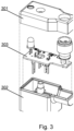
- the device may have its components arranged on a PCB enclosed by a plug configured to connect a power supply to the solenoid valve.
- the invention in another aspect, relates to a method for monitoring operation of a solenoid valve, comprising the steps of: connecting a device as described herein to a coil of the solenoid valve; switching on power supply to the power supply switching transistor; awaiting for a signal at the input of the consumed current amplified measurement channel to exceed the minimum value threshold; examining the slope ( ⁇ ) of the characteristics of the consumed current amplified measurement channel and storing the value of the signal of the consumed current amplified measurement channel when the slope ( ⁇ ) reaches the horizontal, and determining, based on the stored value, the values of the minimum slope ( ⁇ MIN ) , the limit value of the increment ( ⁇ I L ) and the stabilisation value; continuing examination of the slope ( ⁇ ) when the slope ( ⁇ ) falls to a value below the minimum slope, until the direction of the slope ( ⁇ ) changes from descending to ascending and from this point onwards, checking the signal value increment of the consumed current amplified measurement channel and when it exceeds the increment limit value, awaiting for the current value to
- the method and device according to the invention allow monitoring operation of solenoid valves, by tracking the values of current of the solenoid valve coil based on monitoring changes in coil inductance over time.
- the solution according to the invention provides broader diagnostic capabilities than the prior art solutions. In particular, it allows detection of abnormal switching characteristics of the solenoid valve, which can be an early indication of a need to replace the solenoid valve, even before the solenoid valve actually fails.
- a monitoring device according to the present invention can indicate correct switching of the solenoid valve (or lack of correct switching). It also allows, when the coil is short circuited, protecting the power supply source and elements of the path for measuring and controlling the switching of the coil, by cutting off the supply of power to the faulty coil.
- the monitoring device allows to indicate that the supply voltage provided to the coil is too low or too high (via a LED or an IO-Link interface). Furthermore, the solution according to the present invention not only indicates the correct switching of the solenoid valve, but also measures electrical and timing parameters that can be read by the host system and used to assess changes in the operation or wear and tear of the solenoid valve or to schedule maintenance of the solenoid valve.
- the device according to the invention fits into standard solenoid valve power plugs, therefore it can be used to monitor solenoid valves of various manufacturers without having to adjust the device parameters to the specificity of a given solenoid valve.
- an adjustable gain subsystem in a path for measuring a current-time waveform, it was possible to achieve versatility in terms of cooperation with a wide current spectrum of solenoid valves without having to adapt the structure of the device to different coil operating currents.
- the solution according to the invention allows to use the same physical shunt in a form of a measuring resistor in the coil current measurement path for a very diverse range of operating currents of solenoid valve coils available on the market, having values in the order of tens of mA to a few A, and allows use of a shunt (resistor) with a low resistance, which as a result reduces the amount of heat released at the shunt.
- the reference solution for the TIDA-01250 circuit described in the background section would require splitting of the physical layer into dedicated electronic packages for specific operating ranges of solenoid valves, because (due to the measurement range and resolution of the ADC converter) it is not possible to assess correctness of coil current waveform for a specific shunt resistance for such diverse operating current ranges of solenoid valve coils.
- the shunt resistance and the amplifier gain are optimally selected for a group of coils with a specific rated power range, and the use of such a device for a coil significantly different in its rated power from the adopted assumptions causes that the range of the voltage signal reflecting the coil current either exceeds the measuring range of the ADC converter, or changes only in a small measuring range of the ADC converter, which in both cases will result in the inability to correctly assess the coil current shape by the processor algorithm.
- This excludes the versatility of the solution in a commercial sense - one electronic module in the plug for all solenoid valves.
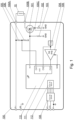
- Fig. 1 shows an example embodiment of a functional diagram of device according to the invention.
- the components of the device are installed within a solenoid valve power plug.
- the device comprises a connection interface to connect it to a coil 10 of a solenoid valve.
- the connection interface comprises a first terminal 100A connected to a supply voltage 2L+ and configured to be connected to a first terminal of the coil 10 of the solenoid valve, and a second terminal 100B configured to be connected to a second terminal of the coil 10 of the solenoid valve.
- the device comprises a power supply switching transistor 101 connected between the second terminal 100B and a measurement resistor 102 connected to a ground (GND) potential of the system.
- the power supply switching transistor 101 is preferably a MOSFET type transistor.
- the power supply switching transistor 101 provides current to the coil in order to switch the solenoid valve on and off.
- the voltage at the measurement resistor 102 at point 100C reflects the power supply current consumed by the coil when it is switched on. This voltage is monitored by a microprocessor-based measurement system 110 that also controls the transistor 101 that switches on the coil power supply via a power supply control output OUT.
- a protection resistor 103 protects the power supply switching transistor 101 from accidentally switching on during an initial phase of operation, after power has been applied to the system, when the microprocessor-based measurement system 110 is just starting up and the power supply control output OUT is not yet controlled by the microprocessor-based measurement system 110 and set as unpolarised. During this period, the protection resistor 103 connects the gate of the power supply switching transistor 101 to the GND potential, which prevents the power supply switching transistor 101 from switching on. When the microprocessor-based measurement system 110 starts and configures the power supply control output OUT, the resistance of the protection resistor 103 is irrelevant in controlling the power supply switching transistor 101.
- the microprocessor-based measurement system 110 comprises an analogue-to-digital converter 111.
- the converter 111 may have a form of a single multi-channel converter, of an assembly of multiple single-channel converters, or of a combination thereof.
- the analogue-to-digital converter 111 has three channels: CH1, CH2, CH3.
- the first channel CH1 is configured to measure the voltage at a voltage divider composed of series-connected resistors 105, 106 and connected between the supply voltage 2L+ of the coil and the GND potential.
- the signal from the analogue-to-digital converter 111 from the first channel CH1 (also referred to as the supply voltage measurement channel) is used to assess the quality of the supply voltage, i.e.
- the second channel CH2 (also referred to as the consumed current measurement channel) is used to measure the voltage at the measurement resistor 102 after filtering through a low-pass filter 104.
- the signal from the low-pass filter 104 is also supplied to an adjustable amplifier 109, the output of which is connected to the third channel CH3 of the analogue-to-digital converter 111.
- the voltage at the measurement resistor 102 at point 100C is proportional to the instantaneous current of the coil.
- This signal may, in addition to the voltage proportional to the coil current, also contain noise (interference) from the power supply path or from the environment wherein the system operates.
- the low-pass filter 104 eliminates these noises by passing only the lower-frequency useful signal that is supplied to the second channel CH2 of the analogue-to-digital converter 111 and to the input of the adjustable amplifier 109.
- the low-pass filter may have a cut-off frequency of 2000 Hz.
- the signal from the adjustable amplifier 109 is supplied to the third channel CH3 of the analogue-to-digital converter 111.
- the measurement resistor 102 has a fixed known value, hence the voltage on the second channel CH2 of the analogue-to-digital converter 111 is proportional to the coil current, with a constant ratio.
- the signal supplied to the second channel CH2 is used to detect a short circuit in the coil 10 of the solenoid valve and to calculate a new gain for the adjustable amplifier 109.
- An occurrence (on the second channel CH2) of a voltage greater than the adopted threshold value considered as the short-circuit threshold, causes the power supply switching transistor 101 to be switched off immediately, by setting the power supply control output OUT to a low state L.
- the signal at the input of the third channel CH3 of the analogue-to-digital converter 111 is the signal amplified by the adjustable amplifier 109, supplied from the low-pass filter 104 - the same as the signal supplied to the input of the second channel CH2.
- the adjustable amplifier 109 allows the low-value signal from the low-pass filter 104 to be adapted to the measurement range of the analogue-to-digital converter 111 in order to monitor the current waveform of the coil 10 with a resolution as high as possible.
- the device can be connected to coils 10 having various powers, which will cause flow of currents of various values.
- the gain in the adjustable amplifier 109 may be adjusted linearly or stepwise, depending on the functionality of the adjustable amplifier 109 used, and the adjustment is performed by the gain signal output GAIN of the microprocessor-based measurement system 110, that may be an analogue output (such as a signal from a digital-to-analogue converter), one or more binary outputs allowing stepwise changes in gain, or a digital interface allowing the microprocessor-based measurement system 110 to set the gain in the adjustable amplifier 109.
- the gain signal output GAIN of the microprocessor-based measurement system 110 may be an analogue output (such as a signal from a digital-to-analogue converter), one or more binary outputs allowing stepwise changes in gain, or a digital interface allowing the microprocessor-based measurement system 110 to set the gain in the adjustable amplifier 109.
- the signal connected to the input of the second channel CH2 of the analogue-to-digital converter 111 is also used (in addition to short-circuit detection) to roughly determine the coil current when, for the actual gain of the adjustable amplifier 109, the signal supplied to the input of the third channel CH3 of the analogue-to-digital converter 111 exceeds its measurement range (this situation may occur, for example, after the coil 10 has been replaced by a coil of a higher power) and the measurements for the second channel CH2 are used to calculate the new gain setting of the adjustable amplifier 109.
- the optimum gain of the adjustable amplifier 109 should be such that the signal at the input of the third channel CH3 of the analogue-to-digital converter 111 (after the current of the coil 10 has stabilised) is approximately 80% of the measurement range of the third channel CH3 of the analogue-to-digital converter 111. The remaining 20% (i.e. the interval from 80-100%) of the measurement range of the analogue-to-digital converter 111 is the measurement margin for a possible increase in the coil current, resulting from changes in supply voltage or from changes in coil or ambient temperature.
- the adjustable amplifier 109 has at least as many possible gain levels that, for the intended range of currents of the coils 10, the signal at the input of the third channel CH3 of the analogue-to-digital converter 111, after stabilisation, has a value in the range from an adopted threshold minimum value LIMIT-MIN to a threshold maximum value LIMIT-MAX, for example equal to about 80% of the measurement range of the analogue-to-digital converter 111.
- the minimum value LIMIT-MIN should be greater than the limit of the possibility of correct switching detection, for example 20% of the measurement range of the analogue-to-digital converter 111.
- adjustable amplifier 109 that will allow the gain to be set so that, irrespective of the coil connected to the system, the signal at the input CH3 of the analogue-to-digital converter 111, after stabilisation of the current of the coil 10, is as close as possible to 80% of the measurement range of the analogue-to-digital converter 111.
- the microprocessor-based measurement system 110 reduces the gain of the adjustable amplifier 109 using the gain signal output GAIN. If the signal at the input CH3 of the analogue-to-digital converter 111 is below the LIMIT-MIN value after stabilisation, the microprocessor-based measurement system 110 increases the gain of the adjustable amplifier 109 using the gain signal output GAIN.
- the microprocessor-based measurement system 110 further comprises an input/output interface 112 connected to an input/output controller 108. Via the input/output interface 112, the user can manually configure the parameters (e.g. gain) for the coil of the solenoid valve with which the device will cooperate - this is particularly useful as the device performs a gain adjustment when first powered up with a new coil, which involves switching on the solenoid valve twice in a short time. Such action may not be advisable for the machine in which the solenoid valve operates. Furthermore, the user can set some specific parameters, such as the thresholds, for which the algorithm checks the successive conditions for switching on the solenoid valve.
- the parameters e.g. gain
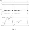
- Fig. 2A shows an example of signal waveforms in a situation when a coil having a much higher power (higher current) is connected to the system as compared to the coil that was connected during the previous switch-on cycle.
- the microprocessor-based measurement system 110 having received a command, via the IO-Link interface, to switch on the solenoid valve, sets the power supply control output OUT to a high state H, which causes the power supply switching transistor 101 to switch on and a current to flow through the coil, wherein said current causes a voltage drop at the measurement resistor 102 (voltage at point 100C) proportional to the coil current.
- the voltage at point 100C is supplied to the input of the second channel CH2 of the analogue-to-digital converter 111, and to the input of the adjustable amplifier 109, while the signal from the amplifier is supplied to the input of the third channel CH3 of the analogue-to-digital converter 111. Because of a high gain set in the adjustable amplifier 109, the signal at the input of the third channel CH3 at a certain moment exceeds the measurement range of the analogue-to-digital converter 111 and of the microprocessor-based measurement system 110. If such situation is detected, the device monitors the signal from the input of the second channel CH2 and waits for it to stabilise.
- the microprocessor-based measurement system 110 measures it and, based on the measurement, calculates and sets the gain of the adjustable amplifier 109, stores the gain setting in non-volatile memory and switches off the coil power supply by setting the power supply control output OUT to a low state L.
- the microprocessor-based measurement system 110 switches the power supply to the coil 10 again by setting the power control output OUT to a high state H which switches on the power supply switching transistor 101 and makes the current flow through the coil and through the measurement resistor 102 at which the voltage drop is proportional to the current, this voltage is supplied to the low-pass filter 104 and then to the input of the second channel CH2 of the analogue-to-digital converter 111 and to the input of the adjustable amplifier 109 which now has a new lower gain value set.
- the amplified signal from the amplifier is supplied to the input of the third channel CH3 of the ADC converter 111.
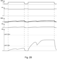
- Fig. 2B shows a signal waveform in a situation when a coil having a much lower power (lower current) is connected to the system as compared to the coil that was connected during the previous switch-on.
- the microprocessor-based measurement system 110 having received a command, via the IO-Link interface, to switch on the solenoid valve, sets the power supply control output OUT to a high state H, which causes the power supply switching transistor 101 to switch on and a current to flow through the coil, said current causing a voltage drop at the measurement resistor 102 (voltage at point 100C) proportional to the current.
- This voltage after filtering out interferences in the low-pass filter 104, is supplied to the input of the second channel CH2 of the analogue-to-digital converter 111, and to the input of the adjustable amplifier 109, and then the signal from the amplifier is supplied to the input of the third channel CH3 of the analogue-to-digital converter 111. Because the gain at the amplifier 109 is set low, the signal at the input of the third channel CH3, once stabilised, is below the lower limit LIMIT-MIN, which indicates the need to increase the gain on the amplifier 109.
- the microprocessor-based measurement system 110 measures it and uses the measured value to calculate the new gain value, then sets the new gain of the adjustable amplifier 109, and stores the gain setting in a non-volatile memory and switches off the coil power supply by setting the power control output OUT to a low state L.
- the microprocessor-based measurement system 110 switches the power supply to the coil again by setting the power control output OUT to a high state H, which switches on the power supply switching transistor 101 and makes the current flow through the coil and through the measurement resistor 102 at which the voltage drop is proportional to the current.
- This voltage is supplied to the low-pass filter 104 and then to the input of the second channel CH2 of the analogue-to-digital converter 111 and to the input of the adjustable amplifier 109 which now has a new higher gain value set.
- the amplified signal from the amplifier is supplied to the input of the third channel CH3 of the analogue-to-digital converter 111.
- Such a mechanism allows coils to be replaced with the same type or a different type (coils with a different current consumption in a steady state, compatible with the mechanics and power plug of the solenoid valve coil) without the need for cumbersome maintenance involving entering new settings into the microcontroller memory for proper operation, although such functionality is provided 'externally' by the interface of the IO-link module integrated in the electronics package. Furthermore, coil replacement does not require physical changes to the electronics package nested in the coil power plug due to the fact that it does not require the need for different shunts in the coil current measurement system.
- Fig. 4 illustrates operation of an algorithm for assessment of a coil current.
- the algorithm waits until the signal at the input of the third channel CH3 of the analogue-to-digital converter 111 exceeds the minimum value threshold I MIN , beyond which, in step 1, the slope of the current curve characteristics is examined.
- the slope of the curve represented by an angle ⁇
- the value I 2 of the signal at the input of the third channel CH3 is stored. Based on the value I 2 , the parameters considered in the following part of the algorithm ( ⁇ MIN , ⁇ I L , I S ) are calculated.
- step 2 the examination of the slope of the characteristics continues until the direction of the characteristics changes from a descending to an ascending one. From this point onwards, the increment of the signal value at the input of the third channel CH3 is checked. When it exceeds the increment limit ⁇ I L , the algorithm proceeds to step 3.
- step 3 the algorithm waits for the current to stabilise, i.e. it checks whether the difference between the maximum and minimum current values, at the time of stabilisation T S from the last measurements was lower than the stabilisation value I S . When the current stabilisation is detected, the algorithm proceeds to step 4, which indicates that the solenoid valve is correctly switched on.
- the system reports a failure of the solenoid valve.
- I 2 is specified as a percentage of the measurement range of the ADC converter.
- the calculated parameters (%) refer to the measurement range of the ADC converter: I MIN ⁇ 3 % ⁇ MIN ⁇ ⁇ 45 ° atan I 2 2 ⁇ 10 % msek ⁇ I L ⁇ I 2 2 ⁇ 15 % I S ⁇ I 2 2 ⁇ 3 % T S ⁇ 5 milliseconds
Landscapes
- Engineering & Computer Science (AREA)
- Physics & Mathematics (AREA)
- Electromagnetism (AREA)
- General Engineering & Computer Science (AREA)
- Power Engineering (AREA)
- Mechanical Engineering (AREA)
- Magnetically Actuated Valves (AREA)
- Control Of Voltage And Current In General (AREA)
Claims (9)
- Vorrichtung zur Überwachung des Betriebs eines Magnetventils, wobei die Vorrichtung umfasst:- eine Schaltung zum Versorgen einer Spule (10) eines Magnetventils mit Strom, die Anschlüsse (100A, 100B) umfasst, die in Reihe mit einer Stromquelle geschaltet sind, wobei die Anschlüsse (100A, 100B) dazu konfiguriert sind, mit der Spule (10), einem Stromversorgungsschalttransistor (101) und einem Messwiderstand (102) verbunden zu werden;- ein mikroprozessorbasiertes Mess-(110)-system, das dazu konfiguriert ist, den von der Spule (10) verbrauchten Versorgungsstrom zu überwachen, während die Spule (10) eingeschaltet ist, indem die Spannung am Messwiderstand (102) gemessen wird, und den Schalttransistor (101) der Stromversorgung zu steuern;dadurch gekennzeichnet, dass:- das mikroprozessorbasierte Messsystem (110):- einen Analog-Digital-Wandler (111) umfasst, der einen Verbrauchsstrom-Messkanal (CH2), der mit dem Messwiderstand (102) verbunden ist, und einen verstärkten Verbrauchsstrom-Messkanal (CH3), der mit dem Verbrauchsstrom-Messkanal (CH2) über einen einstellbaren Verstärker (109) verbunden ist umfasst;- und konfiguriert ist zum:- Ausschalten des Stromversorgungsschalttransistors (101), wenn auf dem Verbrauchsstrom-Messkanal (CH2) eine Spannung mit einem Wert über einem Schwellenwert erkannt wird;- Steuern der Verstärkung (GAIN) des einstellbaren Verstärkers (109) derart, dass das Signal am Eingang des verstärkten Verbrauchsstrom-Messkanals (CH3) geringer ist als der Messbereich dieses Kanals (CH3).
- Vorrichtung nach Anspruch 1, wobei der Analog-Digital-Wandler (111) ferner einen Versorgungsspannungsmesskanal (CH1) umfasst, der mit einem zwischen der Versorgungsspannung (2L+) und der Masse (GND) angeschlossenen resistiven Spannungsteiler (105, 106) verbunden ist, und wobei das mikroprozessorbasierte Messsystem (110) dazu konfiguriert ist, den Bereich der Versorgungsspannung (2L+) und die Spannungsschwankung beim Einschalten der Stromversorgung zu überwachen.
- Vorrichtung nach einem der vorhergehenden Ansprüche, wobei der Verbrauchsstrom-Messkanal (CH2) über einen Tiefpassfilter (104) mit dem Messwiderstand (102) verbunden ist.
- Vorrichtung nach einem der vorhergehenden Ansprüche, wobei das mikroprozessorbasierte Messsystem (110) ferner eine Eingabe-/Ausgabeschnittstelle (112) umfasst, die dazu konfiguriert ist, einen Parameter zu empfangen, der den Verstärkungswert (GAIN) des einstellbaren Verstärkers (109) bestimmt.
- Vorrichtung nach einem der vorhergehenden Ansprüche, wobei das mikroprozessorbasierte Messsystem (110) ferner dazu konfiguriert ist, die Verstärkung (GAIN) des einstellbaren Verstärkers (109) so zu steuern, dass das Signal am Eingang des verstärkten Verbrauchsstrom-Messkanals (CH3) höher ist als der minimale Schwellenwert (LIMIT-MIN).
- Vorrichtung nach einem der vorhergehenden Ansprüche, wobei das mikroprozessorbasierte Messsystem (110) ferner dazu konfiguriert ist, die Verstärkung (GAIN) des einstellbaren Verstärkers (109) so zu steuern, dass das Signal am Eingang des verstärkten Verbrauchstrom-Messkanals (CH3) niedriger ist als der maximale Schwellenwert (LIMIT-MAX).
- Vorrichtung nach Anspruch 6, wobei das mikroprozessorbasierte Messsystem (110) ferner dazu konfiguriert ist, die Verstärkung (GAIN) des einstellbaren Verstärkers (109) so zu steuern, dass das Signal am Eingang des verstärkten Verbrauchsstrom-Messkanals (CH3) nach der Stabilisierung des Spulenstroms nahe am maximalen Schwellenwert (LIMIT-MAX) liegt.
- Vorrichtung nach einem der vorhergehenden Ansprüche, aufweisend Komponenten, die auf einer Leiterplatte (303) angeordnet sind, die von einem Stecker (301, 302) umschlossen ist, der dazu konfiguriert ist, eine Stromversorgung an das Magnetventil anzuschließen.
- Verfahren zur Überwachung des Betriebs eines Magnetventils, umfassend die Schritte:- Verbinden einer Vorrichtung nach einem der vorhergehenden Ansprüche mit einer Spule (10) des Magnetventils;- Einschalten (Schritt 0) der Stromversorgung zum Stromversorgungsschalttransistor (101);- Warten auf ein Signal am Eingang des verstärkten Verbrauchsstrom-Messkanals (CH3), das die Mindestwertschwelle (IMIN) überschreitet;- Untersuchen (Schritt 1) der Steigung (α) der Charakteristik des verstärkten Verbrauchsstrom-Messkanals (CH3) und Speichern des Werts des Signals (I2) des verstärkten Verbrauchsstrom-Messkanals (CH3), wenn die Steigung (α) die Horizontale erreicht, und Bestimmen, basierend auf dem gespeicherten Wert (I2), der Werte der minimalen Steigung (aMIN ), des Grenzwerts der Erhöhung (ΔIL ) und des Stabilisierungswerts (IS);- Fortsetzen der Untersuchung (Schritt 2) der Steigung (α), wenn die Steigung (α) auf einen Wert unterhalb der Mindeststeigung (αMIN) abfällt, bis die Richtung der Steigung (α) von abfallend auf ansteigend wechselt, und ab diesem Zeitpunkt Überprüfen der Signalwerterhöhung des verstärkten Verbrauchsstrom-Messkanals (CH3) und, wenn diese den Erhöhungsgrenzwert (ΔIL) überschreitet, Warten (Schritt 3), bis sich der Stromwert so stabilisiert, dass die Differenz zwischen dem Maximal- und dem Minimalwert während der angegebenen Stabilisierungszeit (TS) kleiner ist als der Stabilisierungswert (IS);- Melden (Schritt 4), dass das Magnetventil ordnungsgemäß eingeschaltet ist, wenn sich der Stromwert innerhalb der vorgegebenen Endstabilisierungszeit (TS) stabilisiert und die Stromstabilisierung nicht später als die zulässige Gesamteinschaltzeit (TZ) seit Überschreiten der Minimalwertschwelle (IMIN) stattfindet; und- Melden, dass das Magnetventil ausgefallen ist, wenn sich der Stromwert nicht vor der vorgegebenen Einschaltzeit (TZ) seit Überschreiten der Mindestwertschwelle (IMIN) stabilisiert.
Applications Claiming Priority (2)
| Application Number | Priority Date | Filing Date | Title |
|---|---|---|---|
| PL438382A PL247468B1 (pl) | 2021-07-08 | 2021-07-08 | Urządzenie do monitorowania pracy elektrozaworu i sposób monitorowania pracy elektrozaworu |
| PCT/EP2022/069069 WO2023281057A2 (en) | 2021-07-08 | 2022-07-08 | A device for monitoring operation of a solenoid valve and a method for monitoring operation of a solenoid valve |
Publications (3)
| Publication Number | Publication Date |
|---|---|
| EP4367694A2 EP4367694A2 (de) | 2024-05-15 |
| EP4367694C0 EP4367694C0 (de) | 2025-03-19 |
| EP4367694B1 true EP4367694B1 (de) | 2025-03-19 |
Family
ID=83689540
Family Applications (1)
| Application Number | Title | Priority Date | Filing Date |
|---|---|---|---|
| EP22786883.3A Active EP4367694B1 (de) | 2021-07-08 | 2022-07-08 | Vorrichtung zur überwachung des betriebs eines magnetventils und verfahren zur überwachung des betriebs eines magnetventils |
Country Status (4)
| Country | Link |
|---|---|
| US (1) | US20240369156A1 (de) |
| EP (1) | EP4367694B1 (de) |
| PL (1) | PL247468B1 (de) |
| WO (1) | WO2023281057A2 (de) |
Families Citing this family (2)
| Publication number | Priority date | Publication date | Assignee | Title |
|---|---|---|---|---|
| CN120103123A (zh) * | 2023-12-06 | 2025-06-06 | 中国石油化工股份有限公司 | 一种多通道电磁阀故障检测装置及方法 |
| WO2025227215A1 (pt) * | 2024-04-30 | 2025-11-06 | Robert Bosch Limitada | Método implementado por computador, sistema e memória lida por computador para monitoramento e manutenção da condição operacional de um componente eletromecânico |
Family Cites Families (4)
| Publication number | Priority date | Publication date | Assignee | Title |
|---|---|---|---|---|
| GB9102789D0 (en) | 1991-02-09 | 1991-03-27 | Norgren Martonair Ltd | Armature movement detection circuit |
| US7746620B2 (en) * | 2008-02-22 | 2010-06-29 | Baxter International Inc. | Medical fluid machine having solenoid control system with temperature compensation |
| WO2017027792A1 (en) * | 2015-08-13 | 2017-02-16 | G.W. Lisk Company, Inc. | Method and apparatus for solenoid position measurement and control |
| IT201700096969A1 (it) * | 2017-08-29 | 2019-03-01 | Camozzi Automation S P A | Dispositivo e metodo di diagnostica per elettrovalvole |
-
2021
- 2021-07-08 PL PL438382A patent/PL247468B1/pl unknown
-
2022
- 2022-07-08 WO PCT/EP2022/069069 patent/WO2023281057A2/en not_active Ceased
- 2022-07-08 US US18/577,323 patent/US20240369156A1/en active Pending
- 2022-07-08 EP EP22786883.3A patent/EP4367694B1/de active Active
Also Published As
| Publication number | Publication date |
|---|---|
| WO2023281057A3 (en) | 2023-02-09 |
| EP4367694A2 (de) | 2024-05-15 |
| EP4367694C0 (de) | 2025-03-19 |
| US20240369156A1 (en) | 2024-11-07 |
| WO2023281057A2 (en) | 2023-01-12 |
| PL438382A1 (pl) | 2023-01-09 |
| PL247468B1 (pl) | 2025-07-07 |
Similar Documents
| Publication | Publication Date | Title |
|---|---|---|
| EP4367694B1 (de) | Vorrichtung zur überwachung des betriebs eines magnetventils und verfahren zur überwachung des betriebs eines magnetventils | |
| RU2413307C2 (ru) | Верификация тока контура управления процесса | |
| MX2015004123A (es) | Dispositivos para interrumpir el circuito basado en el procesador. | |
| US20050099751A1 (en) | Semiconductor device having overcurrent protection function and data setting method thereof | |
| JP4393873B2 (ja) | 送信器 | |
| US8872441B2 (en) | Controller and LED driving circuit with protection function | |
| KR101918253B1 (ko) | 플라즈마 전원장치의 자가진단모듈 및 자가진단방법 | |
| KR102277247B1 (ko) | 펌프 성능 데이터 기반의 설비 제어시스템 및 그 방법 | |
| MXPA06010471A (es) | Dispositivo de disparo electronico equipado con medios de monitoreo, interruptor de circuito que comprende dicho dispositivo de disparo y metodo de monitoreo. | |
| US8659277B2 (en) | Current providing method and current providing system | |
| KR100784887B1 (ko) | 자동차용 모터의 과전류 검출장치 | |
| US8780509B2 (en) | Circuit protection device and protection method | |
| US6181141B1 (en) | Failsafe monitoring system for potentiometers and monitor interface | |
| US4866363A (en) | Fail-safe potentiometer feedback system | |
| US20100286895A1 (en) | Method for monitoring at least one glow plug of an internal combustion engine and corresponding device | |
| US20090267714A1 (en) | Switch-state monitoring device | |
| GB2331414A (en) | Monitoring a current-regulating stage | |
| JP2009089072A (ja) | 電磁負荷装置の制御装置 | |
| US12287626B2 (en) | Device and method for the control of safety apparatuses | |
| JP5009202B2 (ja) | 調節計およびその調整方法 | |
| EP1929391B1 (de) | Integrierte schaltung und verfahren zur auswahl einer spannung in einer integrierten schaltung | |
| KR101487979B1 (ko) | 증폭기 성능 시험에서의 번-아웃 방지 장치 및 그 방법 | |
| JP2012095508A (ja) | パワーコンディショナ | |
| US6259081B1 (en) | Device for receiving a transmission signal and for transmitting an optical beam and method of using the device | |
| CN119448878B (zh) | 一种智能带保护的电机过载过压吸收电路及其控制方法 |
Legal Events
| Date | Code | Title | Description |
|---|---|---|---|
| STAA | Information on the status of an ep patent application or granted ep patent |
Free format text: STATUS: UNKNOWN |
|
| STAA | Information on the status of an ep patent application or granted ep patent |
Free format text: STATUS: THE INTERNATIONAL PUBLICATION HAS BEEN MADE |
|
| PUAI | Public reference made under article 153(3) epc to a published international application that has entered the european phase |
Free format text: ORIGINAL CODE: 0009012 |
|
| STAA | Information on the status of an ep patent application or granted ep patent |
Free format text: STATUS: REQUEST FOR EXAMINATION WAS MADE |
|
| 17P | Request for examination filed |
Effective date: 20240206 |
|
| AK | Designated contracting states |
Kind code of ref document: A2 Designated state(s): AL AT BE BG CH CY CZ DE DK EE ES FI FR GB GR HR HU IE IS IT LI LT LU LV MC MK MT NL NO PL PT RO RS SE SI SK SM TR |
|
| DAV | Request for validation of the european patent (deleted) | ||
| DAX | Request for extension of the european patent (deleted) | ||
| GRAP | Despatch of communication of intention to grant a patent |
Free format text: ORIGINAL CODE: EPIDOSNIGR1 |
|
| STAA | Information on the status of an ep patent application or granted ep patent |
Free format text: STATUS: GRANT OF PATENT IS INTENDED |
|
| INTG | Intention to grant announced |
Effective date: 20241105 |
|
| GRAS | Grant fee paid |
Free format text: ORIGINAL CODE: EPIDOSNIGR3 |
|
| GRAA | (expected) grant |
Free format text: ORIGINAL CODE: 0009210 |
|
| STAA | Information on the status of an ep patent application or granted ep patent |
Free format text: STATUS: THE PATENT HAS BEEN GRANTED |
|
| AK | Designated contracting states |
Kind code of ref document: B1 Designated state(s): AL AT BE BG CH CY CZ DE DK EE ES FI FR GB GR HR HU IE IS IT LI LT LU LV MC MK MT NL NO PL PT RO RS SE SI SK SM TR |
|
| REG | Reference to a national code |
Ref country code: GB Ref legal event code: FG4D |
|
| REG | Reference to a national code |
Ref country code: CH Ref legal event code: EP |
|
| REG | Reference to a national code |
Ref country code: IE Ref legal event code: FG4D |
|
| REG | Reference to a national code |
Ref country code: DE Ref legal event code: R096 Ref document number: 602022012057 Country of ref document: DE |
|
| U01 | Request for unitary effect filed |
Effective date: 20250415 |
|
| U07 | Unitary effect registered |
Designated state(s): AT BE BG DE DK EE FI FR IT LT LU LV MT NL PT RO SE SI Effective date: 20250516 |
|
| PG25 | Lapsed in a contracting state [announced via postgrant information from national office to epo] |
Ref country code: RS Free format text: LAPSE BECAUSE OF FAILURE TO SUBMIT A TRANSLATION OF THE DESCRIPTION OR TO PAY THE FEE WITHIN THE PRESCRIBED TIME-LIMIT Effective date: 20250619 |
|
| PG25 | Lapsed in a contracting state [announced via postgrant information from national office to epo] |
Ref country code: NO Free format text: LAPSE BECAUSE OF FAILURE TO SUBMIT A TRANSLATION OF THE DESCRIPTION OR TO PAY THE FEE WITHIN THE PRESCRIBED TIME-LIMIT Effective date: 20250619 |
|
| PG25 | Lapsed in a contracting state [announced via postgrant information from national office to epo] |
Ref country code: HR Free format text: LAPSE BECAUSE OF FAILURE TO SUBMIT A TRANSLATION OF THE DESCRIPTION OR TO PAY THE FEE WITHIN THE PRESCRIBED TIME-LIMIT Effective date: 20250319 |
|
| PG25 | Lapsed in a contracting state [announced via postgrant information from national office to epo] |
Ref country code: GR Free format text: LAPSE BECAUSE OF FAILURE TO SUBMIT A TRANSLATION OF THE DESCRIPTION OR TO PAY THE FEE WITHIN THE PRESCRIBED TIME-LIMIT Effective date: 20250620 |
|
| U21 | Renewal fee for the european patent with unitary effect paid with additional fee |
Year of fee payment: 4 Effective date: 20250827 |
|
| PG25 | Lapsed in a contracting state [announced via postgrant information from national office to epo] |
Ref country code: SM Free format text: LAPSE BECAUSE OF FAILURE TO SUBMIT A TRANSLATION OF THE DESCRIPTION OR TO PAY THE FEE WITHIN THE PRESCRIBED TIME-LIMIT Effective date: 20250319 |
|
| PG25 | Lapsed in a contracting state [announced via postgrant information from national office to epo] |
Ref country code: ES Free format text: LAPSE BECAUSE OF FAILURE TO SUBMIT A TRANSLATION OF THE DESCRIPTION OR TO PAY THE FEE WITHIN THE PRESCRIBED TIME-LIMIT Effective date: 20250319 |
|
| PG25 | Lapsed in a contracting state [announced via postgrant information from national office to epo] |
Ref country code: PL Free format text: LAPSE BECAUSE OF FAILURE TO SUBMIT A TRANSLATION OF THE DESCRIPTION OR TO PAY THE FEE WITHIN THE PRESCRIBED TIME-LIMIT Effective date: 20250319 |
|
| PG25 | Lapsed in a contracting state [announced via postgrant information from national office to epo] |
Ref country code: CZ Free format text: LAPSE BECAUSE OF FAILURE TO SUBMIT A TRANSLATION OF THE DESCRIPTION OR TO PAY THE FEE WITHIN THE PRESCRIBED TIME-LIMIT Effective date: 20250319 |
|
| PG25 | Lapsed in a contracting state [announced via postgrant information from national office to epo] |
Ref country code: SK Free format text: LAPSE BECAUSE OF FAILURE TO SUBMIT A TRANSLATION OF THE DESCRIPTION OR TO PAY THE FEE WITHIN THE PRESCRIBED TIME-LIMIT Effective date: 20250319 |
|
| PG25 | Lapsed in a contracting state [announced via postgrant information from national office to epo] |
Ref country code: IS Free format text: LAPSE BECAUSE OF FAILURE TO SUBMIT A TRANSLATION OF THE DESCRIPTION OR TO PAY THE FEE WITHIN THE PRESCRIBED TIME-LIMIT Effective date: 20250719 |