EP4366993B1 - Verfahren zur steuerung eines backup-bewegungssteuerungssystems - Google Patents
Verfahren zur steuerung eines backup-bewegungssteuerungssystems Download PDFInfo
- Publication number
- EP4366993B1 EP4366993B1 EP21743091.7A EP21743091A EP4366993B1 EP 4366993 B1 EP4366993 B1 EP 4366993B1 EP 21743091 A EP21743091 A EP 21743091A EP 4366993 B1 EP4366993 B1 EP 4366993B1
- Authority
- EP
- European Patent Office
- Prior art keywords
- steerable wheels
- motion
- wheel brakes
- autonomous vehicle
- lock braking
- Prior art date
- Legal status (The legal status is an assumption and is not a legal conclusion. Google has not performed a legal analysis and makes no representation as to the accuracy of the status listed.)
- Active
Links
Images

Classifications
-
- B—PERFORMING OPERATIONS; TRANSPORTING
- B60—VEHICLES IN GENERAL
- B60T—VEHICLE BRAKE CONTROL SYSTEMS OR PARTS THEREOF; BRAKE CONTROL SYSTEMS OR PARTS THEREOF, IN GENERAL; ARRANGEMENT OF BRAKING ELEMENTS ON VEHICLES IN GENERAL; PORTABLE DEVICES FOR PREVENTING UNWANTED MOVEMENT OF VEHICLES; VEHICLE MODIFICATIONS TO FACILITATE COOLING OF BRAKES
- B60T7/00—Brake-action initiating means
- B60T7/12—Brake-action initiating means for automatic initiation; for initiation not subject to will of driver or passenger
- B60T7/122—Brake-action initiating means for automatic initiation; for initiation not subject to will of driver or passenger for locking of reverse movement
-
- B—PERFORMING OPERATIONS; TRANSPORTING
- B60—VEHICLES IN GENERAL
- B60T—VEHICLE BRAKE CONTROL SYSTEMS OR PARTS THEREOF; BRAKE CONTROL SYSTEMS OR PARTS THEREOF, IN GENERAL; ARRANGEMENT OF BRAKING ELEMENTS ON VEHICLES IN GENERAL; PORTABLE DEVICES FOR PREVENTING UNWANTED MOVEMENT OF VEHICLES; VEHICLE MODIFICATIONS TO FACILITATE COOLING OF BRAKES
- B60T8/00—Arrangements for adjusting wheel-braking force to meet varying vehicular or ground-surface conditions, e.g. limiting or varying distribution of braking force
- B60T8/32—Arrangements for adjusting wheel-braking force to meet varying vehicular or ground-surface conditions, e.g. limiting or varying distribution of braking force responsive to a speed condition, e.g. acceleration or deceleration
- B60T8/88—Arrangements for adjusting wheel-braking force to meet varying vehicular or ground-surface conditions, e.g. limiting or varying distribution of braking force responsive to a speed condition, e.g. acceleration or deceleration with failure responsive means, i.e. means for detecting and indicating faulty operation of the speed responsive control means
- B60T8/885—Arrangements for adjusting wheel-braking force to meet varying vehicular or ground-surface conditions, e.g. limiting or varying distribution of braking force responsive to a speed condition, e.g. acceleration or deceleration with failure responsive means, i.e. means for detecting and indicating faulty operation of the speed responsive control means using electrical circuitry
-
- B—PERFORMING OPERATIONS; TRANSPORTING
- B60—VEHICLES IN GENERAL
- B60W—CONJOINT CONTROL OF VEHICLE SUB-UNITS OF DIFFERENT TYPE OR DIFFERENT FUNCTION; CONTROL SYSTEMS SPECIALLY ADAPTED FOR HYBRID VEHICLES; ROAD VEHICLE DRIVE CONTROL SYSTEMS FOR PURPOSES NOT RELATED TO THE CONTROL OF A PARTICULAR SUB-UNIT
- B60W50/00—Details of control systems for road vehicle drive control not related to the control of a particular sub-unit, e.g. process diagnostic or vehicle driver interfaces
- B60W50/02—Ensuring safety in case of control system failures, e.g. by diagnosing, circumventing or fixing failures
- B60W50/029—Adapting to failures or work around with other constraints, e.g. circumvention by avoiding use of failed parts
-
- B—PERFORMING OPERATIONS; TRANSPORTING
- B60—VEHICLES IN GENERAL
- B60W—CONJOINT CONTROL OF VEHICLE SUB-UNITS OF DIFFERENT TYPE OR DIFFERENT FUNCTION; CONTROL SYSTEMS SPECIALLY ADAPTED FOR HYBRID VEHICLES; ROAD VEHICLE DRIVE CONTROL SYSTEMS FOR PURPOSES NOT RELATED TO THE CONTROL OF A PARTICULAR SUB-UNIT
- B60W60/00—Drive control systems specially adapted for autonomous road vehicles
- B60W60/001—Planning or execution of driving tasks
- B60W60/0015—Planning or execution of driving tasks specially adapted for safety
- B60W60/0018—Planning or execution of driving tasks specially adapted for safety by employing degraded modes, e.g. reducing speed, in response to suboptimal conditions
-
- B—PERFORMING OPERATIONS; TRANSPORTING
- B60—VEHICLES IN GENERAL
- B60T—VEHICLE BRAKE CONTROL SYSTEMS OR PARTS THEREOF; BRAKE CONTROL SYSTEMS OR PARTS THEREOF, IN GENERAL; ARRANGEMENT OF BRAKING ELEMENTS ON VEHICLES IN GENERAL; PORTABLE DEVICES FOR PREVENTING UNWANTED MOVEMENT OF VEHICLES; VEHICLE MODIFICATIONS TO FACILITATE COOLING OF BRAKES
- B60T2260/00—Interaction of vehicle brake system with other systems
- B60T2260/02—Active Steering, Steer-by-Wire
-
- B—PERFORMING OPERATIONS; TRANSPORTING
- B60—VEHICLES IN GENERAL
- B60T—VEHICLE BRAKE CONTROL SYSTEMS OR PARTS THEREOF; BRAKE CONTROL SYSTEMS OR PARTS THEREOF, IN GENERAL; ARRANGEMENT OF BRAKING ELEMENTS ON VEHICLES IN GENERAL; PORTABLE DEVICES FOR PREVENTING UNWANTED MOVEMENT OF VEHICLES; VEHICLE MODIFICATIONS TO FACILITATE COOLING OF BRAKES
- B60T2270/00—Further aspects of brake control systems not otherwise provided for
- B60T2270/40—Failsafe aspects of brake control systems
- B60T2270/402—Back-up
-
- B—PERFORMING OPERATIONS; TRANSPORTING
- B60—VEHICLES IN GENERAL
- B60W—CONJOINT CONTROL OF VEHICLE SUB-UNITS OF DIFFERENT TYPE OR DIFFERENT FUNCTION; CONTROL SYSTEMS SPECIALLY ADAPTED FOR HYBRID VEHICLES; ROAD VEHICLE DRIVE CONTROL SYSTEMS FOR PURPOSES NOT RELATED TO THE CONTROL OF A PARTICULAR SUB-UNIT
- B60W50/00—Details of control systems for road vehicle drive control not related to the control of a particular sub-unit, e.g. process diagnostic or vehicle driver interfaces
- B60W50/02—Ensuring safety in case of control system failures, e.g. by diagnosing, circumventing or fixing failures
- B60W50/029—Adapting to failures or work around with other constraints, e.g. circumvention by avoiding use of failed parts
- B60W2050/0292—Fail-safe or redundant systems, e.g. limp-home or backup systems
-
- B—PERFORMING OPERATIONS; TRANSPORTING
- B60—VEHICLES IN GENERAL
- B60W—CONJOINT CONTROL OF VEHICLE SUB-UNITS OF DIFFERENT TYPE OR DIFFERENT FUNCTION; CONTROL SYSTEMS SPECIALLY ADAPTED FOR HYBRID VEHICLES; ROAD VEHICLE DRIVE CONTROL SYSTEMS FOR PURPOSES NOT RELATED TO THE CONTROL OF A PARTICULAR SUB-UNIT
- B60W50/00—Details of control systems for road vehicle drive control not related to the control of a particular sub-unit, e.g. process diagnostic or vehicle driver interfaces
- B60W50/02—Ensuring safety in case of control system failures, e.g. by diagnosing, circumventing or fixing failures
- B60W50/029—Adapting to failures or work around with other constraints, e.g. circumvention by avoiding use of failed parts
- B60W2050/0295—Inhibiting action of specific actuators or systems
Definitions
- the present invention relates to a method of controlling a backup motion control system.
- the present invention also relates to a corresponding backup motion control system.
- the present invention is in particular advantageously implemented in an autonomous vehicle.
- the invention will mainly be directed to an autonomous vehicle in the form of a truck, the invention may also be applicable for other types of autonomous vehicles, such as e.g. working machines, cars, etc.
- autonomous vehicles The technology of autonomous vehicles is on a steady development and autonomous vehicles are being applied in a wide variety of applications.
- a physical operator of the vehicle can be superfluous which provides for a number of advantages, such as e.g. increasing the operational capacity of the vehicles, reduction of cost, and increased safety.
- the autonomous vehicles can be operated at e.g. hazardous work sites and thereby avoiding potential accidents for an operator otherwise operating the vehicle.
- braking system(s) and steering system(s) operate as desired and in a more or less fail safe manner for the vehicle to operate as desired and to brake when needed.
- a method of controlling a backup motion control system for an autonomous vehicle comprising a primary steering system for controlling steering operations of a pair of steerable wheels, wherein each of the steerable wheels comprises a wheel brake, the wheel brakes being connected to an anti-lock braking system for preventing the wheel brakes from being locked when the anti-lock braking system is arranged in an enabled state
- the method comprising determining a current motion for the autonomous vehicle, the current motion being generated by a steering operation of the pair of steerable wheels caused by the primary steering system; comparing the current motion with a desired motion for the autonomous vehicle; and when a difference between the current motion and the desired motion exceeds a predetermined threshold limit: controlling the anti-lock braking system for the wheel brakes of the steerable wheels to be arranged in a disabled state; and engaging the wheel brakes of each of the steerable wheels.
- the wording anti-lock braking system should be construed as a system which prevents the wheels from being locked during braking.
- the anti-lock braking system reduces the applied brake pressure or applied brake force on the wheel brake for the specific wheel such that the wheel is no longer locked.
- the enabled state is thus a state where the anti-lock braking system is activated and in operation. In the disabled state, the anti-lock braking system is thus inactivated and not in operation.
- the anti-lock braking system is arranged in the disabled state, the wheels are able to be locked, i.e. the anti-lock braking system does not intervene in the braking action.
- the anti-lock braking system can be a conventional anti-braking system (ABS system), an electronic stability control system (ESP system), dynamic stability control system (DSC system), or other similar system.
- ABS system conventional anti-braking system
- ESP system electronic stability control system
- DSC system dynamic stability control system
- the anti-lock braking system can be configured to be arranged in the disabled state for one or more wheel brakes, while at the same time be arranged in the enabled state for one or more of the other wheel brakes on the vehicle.
- the anti-lock braking system may thus be arranged in an enabled state where intervention is enabled.
- the anti-lock braking system may also be arranged in a disabled state where the system is enabled but intervention is disabled, and a disabled state where the system is fully disabled, and hence intervention is hereby also disabled.
- the current motion for the autonomous vehicle should be construed as relating to the present heading for the vehicle. This could, as will be described below, be based on the current steering direction of the vehicle or lateral deviation from a lane of the road.
- the current motion can be a derivative of the current steering direction of the vehicle or the lateral deviation.
- the current motion can also be the current yaw rate of the vehicle.
- the desired motion is thus an intended and desired heading of the vehicle.
- the desired motion can be based on a desired steering direction or a lateral position of a lane of the road.
- the desired motion can also be a derivative of the desired steering direction or the lateral position.
- the desired motion can also be the desired yaw rate of the vehicle.
- the desired motion can be determined based on data received from a vehicle autonomous steering system, and be based on GPS data, etc.
- the present invention is based on the unexpected insight that by arranging the anti-braking system in a disabled state and activate the wheel brake of the steerable wheels, the friction usage of the friction between the wheel tire surface and the road can be oversaturated. Hence, the invention enables for usage of substantially all friction with the braking action. Since the anti-lock braking system is disabled, the brake force is allowed to be larger than what would be possible with an enabled anti-lock braking system. Put it differently, when the anti-lock braking system is disabled and the brakes are locked, the wheel is changed from a rolling friction state to a wheel slip friction state, in which wheel slip friction state the braking distance is either longer or shorter compared to the rolling friction state.
- the friction parameter of the friction between the wheel and the road surface is in the wheel slip friction state often of a lower value compared to the corresponding friction parameter in the rolling friction state.
- the brake force uses the friction to provide a braking action in the longitudinal direction of the vehicle.
- there is substantially no friction left to generate lateral wheel forces i.e. the so-called lateral slip is increased.
- This will result in a situation where the vehicle is more or less unable to steer to the left hand side or the right hand side, whereby the vehicle will drive substantially straight ahead as seen in the current steering direction, i.e. in the tangential direction, until finally being stopped by the braking action.
- An advantage is thus that the effects of a malfunctioning steering system, regardless of the root cause for such malfunction, can be handled in an efficient manner which reduces the risk that the vehicle will leave the ego lane and drive off the road, etc.
- the above described method is thus advantageously operated as a backup when the ordinary, i.e. primary, steering system fails to function as desired and/or intended.
- the wheel brakes may be applied by a brake force, wherein a magnitude of the brake force is based on the difference between the current motion and the desired motion.
- a magnitude of the brake force is based on the difference between the current motion and the desired motion.
- the wheel brakes of each of the steerable wheels may be engaged by a brake force having a maximum brake force capability, the wheel brakes being engaged by a brake force corresponding to the maximum brake force capability when the difference between the current motion and the desired motion exceeds the predetermined threshold limit.
- An advantage is that the maximum available brake force is applied to the wheel brakes of the steerable wheels. Thus, no intelligent software functionality is necessary that would otherwise calculate and apply a suitable brake force. In the example embodiment at hand, the backup motion control system simply applies the wheel brake as hard as possible.
- the current motion may be associated with a steering angle of the steerable wheels
- the desired path may be associated with a curve angle of a road currently operated by the autonomous vehicle
- the method further comprising alternatingly engaging and disengaging the wheel brakes of each of the steerable wheels when the steering angle exceeds the curve angle.
- the backup motion control system can continuously determine if, after a short braking event, the current motion has been compensated such that it substantially corresponds to the desired motion.
- the lateral forces of the steerable wheels can hereby be balanced, and the vehicle can be controlled back to its intended and desired motion.
- the autonomous vehicle may comprise at least one pair of non-steerable wheels, each of the non-steerable wheels comprising a wheel brake, wherein the method comprises engaging the wheel brakes of each of the non-steerable wheels when the difference between the current motion and the desired motion exceeds the predetermined threshold limit.
- the wheel brakes of the non-steerable wheels may be connected to a second anti-lock braking system, the method comprising controlling the second anti-lock braking system for the wheel brakes of the non-steerable wheels to be arranged in an enabled state for preventing the wheel brakes of the non-steerable wheels to lock when being engaged.
- the second anti-lock braking system may form part of the above described anti-lock braking system, or be a separate anti-lock braking system.
- the wheel brakes of the non-steerable wheels may have an enabled anti-lock braking system at the same time as the anti-lock braking system of the steerable wheels is disabled.
- An advantage is that the non-steerable wheels will be prevented from being locked when operating the backup motion control system.
- the wheel brakes of the non-steerable wheels operate in a conventional manner.
- the current motion may be a current steering direction for the autonomous vehicle
- the desired motion may be a desired path to follow by the autonomous vehicle.
- the desired path can, for example, be a predefined path of a confined work site, etc.
- the method may further comprise determining a current lateral position of the autonomous vehicle relative to a road lane of the desired path for autonomous vehicle; comparing the current lateral position with a predetermined maximum allowable deviation from a lateral center position of the road lane; and controlling the anti-lock braking system for the wheel brakes of the steerable wheels to be arranged in a disabled state and engaging the wheel brakes of each of the steerable wheels only when the current lateral position exceeds the predetermined maximum allowable deviation.
- the desired motion may be a curve direction of a road currently operated by the autonomous vehicle.
- a backup motion control system for an autonomous vehicle comprising a pair of steerable wheels, wherein each of the steerable wheels comprises a wheel brake controllable by the backup motion control system, wherein the backup motion control system is connectable to an anti-lock braking system configured to prevent the wheel brakes from being locked when the anti-lock braking system is arranged in an enabled state
- the backup motion control system comprises a control unit comprising control circuitry configured to receive a signal indicative of a current motion for the autonomous vehicle; compare the current motion with a desired motion for the autonomous vehicle; and when a difference between the current motion and the desired motion exceeds a predetermined threshold limit: transmit a control signal to the anti-lock braking system, the control signal representing instructions causing the anti-lock braking system for the wheel brakes of the steerable wheels to be arranged in a disabled state; and control the wheel brakes of each of the steerable wheels to be engaged.
- an autonomous vehicle comprising a pair of steerable wheels, a primary steering system configured to control a steering operation of the steerable wheels, and a backup motion control system according to the above described second aspect.
- a computer program comprising program code means for performing the steps of any one of the embodiments described above in relation to the first aspect when the program code means is run on a computer.
- a computer readable medium carrying a computer program means for performing the steps of any one of the embodiments described above in relation to the first aspect when the program means is run on a computer.
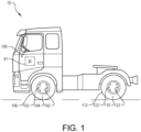
- a vehicle 10 in the form of a truck there is depicted a vehicle 10 in the form of a truck.
- the vehicle 10 is an autonomous vehicle in which steering, and propulsion is autonomously controlled by a control unit 41.
- the autonomous vehicle thus comprises a steering system 100 including a pair of steerable wheels 104, 106.
- the steerable wheels 104, 106 are depicted as the front wheels, but could of course also be the rear wheels.
- the vehicle 10 also comprises a pair of non-steerable wheels 110, 112, which in Fig. 1 is exemplified as the rear wheels.
- the vehicle 10 may comprise additional rear wheels (see 310 and 312 in Fig. 3 ). Such additional rear wheels can, as illustrated in Fig.
- the control unit 41 is preferably connected, directly or indirectly, to a backup motion control system of the autonomous vehicle as will be described in further detail below.
- Steering operation of the steerable wheels 104, 106 is controlled by a primary steering system 100.
- the steering system 100 is depicted as comprising a steering wheel merely for illustrative purpose. Since the vehicle is an autonomous vehicle, the steering wheel may be superfluous.
- the vehicle 10 also comprises a wheel brake 102 connected to each of the steerable wheels 102, 104, as well as a wheel brake 122 connected to the non-steerable wheels 110, 112.
- the wheel brakes are connected to an anti-lock braking system.
- the anti-lock braking system is configured to prevent the wheel brakes from being locked.
- the wheel brakes 102 of the steerable wheels 104, 106 may be connected to a first anti-lock braking system, while the wheel brakes 122 of the non-steerable wheels 110, 112 may be connected to a second anti-lock braking system which is controlled independently of the first anti-lock braking system.
- the wheel brakes 102 of the steerable wheels 104, 106 and the wheel brakes 122 of the non-steerable wheels are connected to one and the same anti-lock braking system.
- Such single anti-lock braking system can enable the anti-lock braking functionality for e.g. the wheel brakes 122 of the non-steerable wheels 110, 112, while at the same time disable the anti-lock braking functionality for e.g. the wheel brakes 102 of the steerable wheels 104, 106, and vice versa.
- the anti-lock braking system is thus arranged to be individually controllable for the wheel brakes.
- the anti-lock braking system may be an integrated control functionality of the control unit 41.
- the control unit 41 may form part of an overall vehicle control system implemented on one or more vehicle unit computers (VUC).
- VUC may be configured to execute vehicle control methods which are organized according to a layered functional architecture where some functionality may be comprised in a traffic situation management (TSM) domain in a higher layer.
- TSM traffic situation management
- the TSM function plans driving operation with a time horizon of, e.g., 10 seconds or so. This time frame corresponds to, e.g., the time it takes for the vehicle to negotiate a curve.
- the vehicle maneuvers, planned and executed by the TSM can be associated with acceleration profiles and curvature profiles which describe a desired vehicle velocity and turning for a given maneuver.
- the TSM continuously requests the desired acceleration profiles a req and curvature profiles c req from the VMM function which performs force allocation to meet the requests from the TSM in a safe and robust manner.
- control unit 41 may include a control circuitry, microprocessor, microcontroller, programmable digital signal processor or another programmable device.
- the control unit may also, or instead, include an application specific integrated circuit, a programmable gate array or programmable array logic, a programmable logic device, or a digital signal processor.
- the control unit includes a programmable device such as the microprocessor, microcontroller or programmable digital signal processor mentioned above, the processor may further include computer executable code that controls operation of the programmable device.
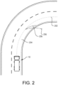
- Fig. 2 is a top view of the vehicle 10 driving along a road curvature.
- the vehicle 10 is aiming to follow a road trajectory 202, which in Fig. 2 is depicted as the lateral center of the lane 204 the vehicle 10 is following.
- the road trajectory 202 represents a desired motion for the vehicle 10.
- the current motion may deviate from the road trajectory 202, i.e. the vehicle 10 is, when operating the road curvature, not following the road trajectory and is instead following a current motion such that the vehicle is about to excessively leave the road. This is depicted by the current motion denoted as 206.
- the control unit 41 controls the anti-lock braking system for the wheel brakes 102 of the steerable wheels 104, 106 to be arranged in a disabled state.
- the control unit 41 also controls the wheel brakes 102 of the steerable wheels 104, 106 to be engaged. Since the anti-lock braking system is disabled, the wheel brakes can apply more or less full brake power and potentially be locked depending on the current friction between the wheel and road surface.
- the wheel brakes of each of the steerable wheels 104, 106 are engaged by a brake force having a maximum brake force capability.
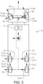
- FIG. 3 is a schematic illustration from above depicting an example embodiment of the vehicle in Fig. 1 exposed to a turning maneuver according to an example embodiment.
- the front steerable wheels 104, 106 is turning the vehicle.
- the front steerable wheels 104, 106 are exposed to a longitudinal wheel force F x,104 , F x,106 and a lateral wheel force F y,104 , F y,106 , respectively.
- the non-steerable wheels 110, 112 are also exposed to a longitudinal wheel force F x,110 , F x,112 and a lateral wheel force F y,110 , F y,112 , respectively.
- the embodiment depicted in Fig. 3 also comprises a rearmost pair of wheels 310, 312.
- the rearmost pair of wheels 310, 312 may be either steerable or non-steerable.
- the wheel brakes of the rearmost pair of wheels 310, 312 are also exposed to a longitudinal wheel force F x,310 , F x,312 and a lateral wheel force F y,310 , F y,312 , respectively.
- the anti-lock braking system for the wheel brakes 102 of the steerable wheels 104, 106 When the anti-lock braking system for the wheel brakes 102 of the steerable wheels 104, 106 are arranged in the disabled state, and the wheel brakes of each of the steerable wheels 104, 106 are engaged by a brake force having a maximum brake force capability, substantially all brake force will be in the longitudinal direction, i.e. the lateral wheel force F y,104 , F y,106 will be substantially zero.
- the vehicle will be understeered and follow the tangential direction, thereby reducing the steering angle, and prevent the vehicle from leaving the road.
- the friction between the steerable wheels 104, 106 and the road will be more or less saturated in the longitudinal direction of the steerable wheels 104, 106.
- the wheel brakes 122 of the non-steerable wheels 110, 112 are also engaged with the anti-lock braking system for these brakes enabled. This will assist in reducing the speed of the vehicle to a final stand-still. In such situation, the non-steerable wheels 110, 112 are still exposed to the lateral forces F y,110 , F y,112 .
- Fig. 2 further depicts another steering operation, indicated with reference numeral 208, which is less severe compared to the above described operating condition where the vehicle follows the trajectory indicated by reference numeral 206. Nevertheless, steering operation resulting in the trajectory denoted by reference numeral 208 is an indication of a malfunctioning steering system. Since this steering operation is less severe, the wheel brakes can be applied with a lower brake force compared to the above described brake force applied when the vehicle followed trajectory 206. The magnitude of the applied brake force can thus be based on the difference between the current motion and the desired motion, with the anti-lock braking system for the wheel brakes 102 of the steerable wheels 104, 106 disabled.
- the wheel brakes 102 of the steerable wheels 104, 106 may be alternatingly engaged and disengaged based on a difference between the current motion and the desired motion.
- the current motion may preferably be a current steering direction for the vehicle 10, and the desired motion may be a desired path to follow by the vehicle 10.
- control unit 41 may be configured to determine a difference between the current motion and the desired motion.
- the control unit may further determine or predict a coming trajectory of the vehicle 10 during braking with the anti-lock braking system enabled, as well as to determine or predict a coming trajectory of the vehicle 10 with the anti-lock braking system disabled.
- the control unit can compare the coming trajectory with the enabled anti-lock braking system and the coming trajectory with the disabled anti-lock braking system.
- the comparison may preferably be made in relation to e.g. a road map, or equivalent. Based on the comparison and the road map data, the control unit determines whether to enable or disable the anti-lock braking system, and controls the wheel brakes to be applied.
- Fig. 4 is a flow chart of a method of controlling the backup motion control system for the vehicle.
- the control unit 41 determines S1 a current motion of the vehicle 10.
- the current motion is generated by a steering operation of the pair of steerable wheels 104, 106 caused by the primary steering system 100.
- the control unit 41 compares S2 the current motion with a desired motion for the vehicle 10.
- the current motion may thus not correspond to the desired motion but may take, as an example, the form as depicted with reference numerals 206 or 208 in Fig. 2 .
- the control unit transmits a control signal to the anti-lock braking system such that the anti-lock braking system for the wheel brakes of the steerable wheels is arranged in the disabled state.
- the transmitted control signal represents instructions causing the anti-lock braking system for the wheel brakes of the steerable wheels to be arranged in a disabled state.
- the control unit controls (S3) the anti-lock braking system to be arranged in the disabled state.
- the control unit 41 also controls the wheel brakes 102 to be engaged (S4). As described above, the vehicle will not continue to follow the erroneous path, but instead follow a tangential direction from the point in time when the brakes are engaged, while at the same time reduce the speed until the vehicle is arranged in a stand-still operation.
Landscapes
- Engineering & Computer Science (AREA)
- Transportation (AREA)
- Mechanical Engineering (AREA)
- Automation & Control Theory (AREA)
- Human Computer Interaction (AREA)
- Steering Control In Accordance With Driving Conditions (AREA)
- Regulating Braking Force (AREA)
Claims (13)
- Verfahren zur Steuerung eines Backup-Bewegungssteuerungssystems für ein autonomes Fahrzeug, das autonome Fahrzeug umfassend ein primäres Lenksystem zur Steuerung von Lenkvorgängen eines Paars lenkbarer Räder, wobei jedes der lenkbaren Räder eine Radbremse umfasst, wobei die Radbremsen mit einem Antiblockiersystem verbunden sind, um zu verhindern, dass die Radbremsen blockiert werden, wenn das Antiblockiersystem in einem aktivierten Zustand angeordnet ist, das Verfahren umfassend:- Bestimmen (S1) einer aktuellen Bewegung für das autonome Fahrzeug, wobei die aktuelle Bewegung durch einen Lenkvorgang des Paars lenkbarer Räder erzeugt wird, der durch das primäre Lenksystem verursacht wird;- Vergleichen (S2) der aktuellen Bewegung mit einer gewünschten Bewegung des autonomen Fahrzeugs;gekennzeichnet durch, wenn eine Differenz zwischen der aktuellen Bewegung und der gewünschten Bewegung einen vorbestimmten Schwellenwert überschreitet:- Steuern (S3) des Antiblockiersystems für die Radbremsen der lenkbaren Räder, um sie in einen deaktivierten Zustand zu versetzen; und- Betätigen (S4) der Radbremsen an jedem der lenkbaren Räder.
- Verfahren nach Anspruch 1, wobei die Radbremsen durch eine Bremskraft betätigt werden, wobei eine Größe der Bremskraft auf der Differenz zwischen der aktuellen Bewegung und der gewünschten Bewegung basiert.
- Verfahren nach einem der Ansprüche 1 oder 2, wobei die Radbremsen jedes der lenkbaren Räder mit einer Bremskraft betätigt werden, die ein maximales Bremskraftvermögen aufweist, wobei die Radbremsen mit einer Bremskraft betätigt werden, die dem maximalen Bremskraftvermögen entspricht, wenn die Differenz zwischen der aktuellen Bewegung und der gewünschten Bewegung den vorbestimmten Schwellenwert überschreitet.
- Verfahren nach einem der vorhergehenden Ansprüche, wobei die aktuelle Bewegung einem Lenkwinkel der lenkbaren Räder zugeordnet ist und die gewünschte Bewegung einem Kurvenwinkel einer Straße zugeordnet ist, die das autonome Fahrzeug gerade befährt, das Verfahren ferner umfassend:- abwechselndes Betätigen und Lösen der Radbremsen jedes der lenkbaren Räder, wenn der Lenkwinkel den Kurvenwinkel überschreitet.
- Verfahren nach einem der vorhergehenden Ansprüche, wobei das autonome Fahrzeug mindestens ein Paar nicht lenkbarer Räder umfasst, wobei jedes der nicht lenkbaren Räder eine Radbremse umfasst, wobei das Verfahren umfasst:- Betätigen der Radbremsen jedes der nicht lenkbaren Räder, wenn die Differenz zwischen der aktuellen Bewegung und der gewünschten Bewegung den vorbestimmten Schwellenwert überschreitet.
- Verfahren nach Anspruch 5, wobei die Radbremsen der nicht lenkbaren Räder mit einem zweiten Antiblockiersystem verbunden sind, das Verfahren umfassend:- Steuern des zweiten Antiblockiersystems für die Radbremsen der nicht lenkbaren Räder, das in einem aktivierten Zustand angeordnet wird, um zu verhindern, dass die Radbremsen der nicht lenkbaren Räder blockieren, wenn sie betätigt werden.
- Verfahren nach einem der vorhergehenden Ansprüche, wobei die aktuelle Bewegung eine aktuelle Lenkrichtung für das autonome Fahrzeug ist und die gewünschte Bewegung ein gewünschter Pfad ist, dem das autonome Fahrzeug folgen soll.
- Verfahren nach Anspruch 7, ferner umfassend:- Bestimmen einer aktuellen seitlichen Position des autonomen Fahrzeugs relativ zu einer Fahrspur des gewünschten Pfades für das autonome Fahrzeug;- Vergleichen der aktuellen seitlichen Position mit einer vorbestimmten maximal zulässigen Abweichung von einer seitlichen Mittelposition der Fahrspur; und- Steuern des Antiblockiersystems für die Radbremsen der lenkbaren Räder, so dass es in einem deaktivierten Zustand angeordnet ist und die Radbremsen jedes der lenkbaren Räder nur dann betätigt werden, wenn die aktuelle seitliche Position die vorbestimmte maximal zulässige Abweichung überschreitet.
- Verfahren nach einem der vorhergehenden Ansprüche, wobei die gewünschte Bewegung eine Kurvenrichtung einer Straße ist, die das autonome Fahrzeug gerade fährt.
- Backup-Bewegungssteuerungssystem für ein autonomes Fahrzeug (10), umfassend ein Paar lenkbare Räder (104, 106), wobei jedes der lenkbaren Räder eine Radbremse (102) umfasst, die durch das Backup-Bewegungssteuerungssystem steuerbar ist, wobei das Backup-Bewegungssteuerungssystem mit einem Antiblockiersystem verbunden werden kann, das konfiguriert ist, um zu verhindern, dass die Radbremsen blockiert werden, wenn das Antiblockiersystem in einem aktivierten Zustand angeordnet ist, wobei das Backup-Bewegungssteuerungssystem eine Steuereinheit (41) umfasst, die eine Steuerschaltung umfasst, die konfiguriert ist, zum:- Empfangen eines Signals, das eine aktuelle Bewegung des autonomen Fahrzeugs anzeigt;- Vergleichen der aktuellen Bewegung mit einer gewünschten Bewegung des autonomen Fahrzeugs;dadurch gekennzeichnet, dass die Steuerschaltung ferner konfiguriert ist, wenn eine Differenz zwischen der aktuellen Bewegung und der gewünschten Bewegung einen vorbestimmten Schwellenwert überschreitet, zum:∘ Übertragen eines Steuersignals an das Antiblockiersystem, wobei das Steuersignal Anweisungen darstellt, die bewirken, dass das Antiblockiersystem für die Radbremsen der lenkbaren Räder in einen deaktivierten Zustand versetzt wird; und∘ Steuern der Radbremsen jedes lenkbaren Rades, um sie zu betätigen.
- Autonomes Fahrzeug mit einem Paar lenkbarer Räder, einem primären Lenksystem (100), das konfiguriert ist, um einen Lenkvorgang der lenkbaren Räder zu steuern, und ein Backup-Bewegungssteuerungssystem nach Anspruch 10.
- Computerprogramm, das Programmcodemittel zum Durchführen der Schritte nach einem der Ansprüche 1-9 umfasst, wenn das Programmcodemittel auf einem Computer ausgeführt wird.
- Computerlesbares Medium mit einem Computerprogramm, das Programmcodemittel zum Durchführen der Schritte nach einem der Ansprüche 1-9 umfasst, wenn das Programmmittel auf einem Computer ausgeführt wird.
Applications Claiming Priority (1)
| Application Number | Priority Date | Filing Date | Title |
|---|---|---|---|
| PCT/EP2021/068761 WO2023280394A1 (en) | 2021-07-07 | 2021-07-07 | A method of controlling a backup motion control system |
Publications (2)
| Publication Number | Publication Date |
|---|---|
| EP4366993A1 EP4366993A1 (de) | 2024-05-15 |
| EP4366993B1 true EP4366993B1 (de) | 2025-06-18 |
Family
ID=76971846
Family Applications (1)
| Application Number | Title | Priority Date | Filing Date |
|---|---|---|---|
| EP21743091.7A Active EP4366993B1 (de) | 2021-07-07 | 2021-07-07 | Verfahren zur steuerung eines backup-bewegungssteuerungssystems |
Country Status (6)
| Country | Link |
|---|---|
| US (1) | US20240278806A1 (de) |
| EP (1) | EP4366993B1 (de) |
| KR (1) | KR20240029022A (de) |
| CN (1) | CN117651663A (de) |
| AU (1) | AU2021454747A1 (de) |
| WO (1) | WO2023280394A1 (de) |
Family Cites Families (4)
| Publication number | Priority date | Publication date | Assignee | Title |
|---|---|---|---|---|
| US8935071B2 (en) * | 2011-05-05 | 2015-01-13 | GM Global Technology Operations LLC | Optimal fusion of electric park brake and hydraulic brake sub-system functions to control vehicle direction |
| JP5898746B1 (ja) * | 2014-09-29 | 2016-04-06 | 富士重工業株式会社 | 車両の走行制御装置 |
| EP3090907B1 (de) * | 2015-05-05 | 2020-08-12 | Volvo Car Corporation | Sekundäre lenksystemeinheit, sekundäres lenksystem, fahrzeug und verfahren für sekundäre lenkung |
| EP3363698B1 (de) * | 2017-02-15 | 2021-05-26 | Volvo Car Corporation | Sicherheitsstoppvorrichtung und autonomes strassenfahrzeug damit |
-
2021
- 2021-07-07 KR KR1020247000564A patent/KR20240029022A/ko active Pending
- 2021-07-07 AU AU2021454747A patent/AU2021454747A1/en active Pending
- 2021-07-07 CN CN202180100165.4A patent/CN117651663A/zh active Pending
- 2021-07-07 EP EP21743091.7A patent/EP4366993B1/de active Active
- 2021-07-07 WO PCT/EP2021/068761 patent/WO2023280394A1/en not_active Ceased
- 2021-07-07 US US18/573,529 patent/US20240278806A1/en active Pending
Also Published As
| Publication number | Publication date |
|---|---|
| AU2021454747A1 (en) | 2024-01-04 |
| CN117651663A (zh) | 2024-03-05 |
| KR20240029022A (ko) | 2024-03-05 |
| WO2023280394A1 (en) | 2023-01-12 |
| US20240278806A1 (en) | 2024-08-22 |
| EP4366993A1 (de) | 2024-05-15 |
Similar Documents
| Publication | Publication Date | Title |
|---|---|---|
| US9014921B2 (en) | Method and system for regulating driving stability | |
| US12168436B2 (en) | Vehicle motion control apparatus, vehicle motion control method, and vehicle motion control system | |
| EP3057848B1 (de) | Verfahren zur steuerung des fahrzeugverhaltens | |
| CN103029703A (zh) | 车辆的车道变换辅助系统及其方法 | |
| US11427253B2 (en) | Method and system for collision avoidance | |
| CN105818811A (zh) | 一种车辆紧急转向避撞时esp与eps联合控制方法 | |
| US20250042372A1 (en) | Brake-to-steer lateral stability management based on stability indicator correlation | |
| CN107848509A (zh) | 用于在路面上积水打滑时辅助驾驶员的方法 | |
| KR102289902B1 (ko) | 차동 휠 제동으로 차량 조향 서포트를 제공하는 방법, 시스템, 차량, 컴퓨터 프로그램 및 컴퓨터-판독 가능 매체 | |
| US20250042404A1 (en) | Brake-to-steer lateral stability management based on stability indicator correlation | |
| US20250042391A1 (en) | Brake-to-steer lateral stability management based on stability indicator correlation | |
| KR101464883B1 (ko) | 요 레이트를 이용한 차량 충돌 방지 방법 | |
| CN115771502B (zh) | 用于爆胎车辆控制的方法、装置、车辆和存储介质 | |
| EP4366993B1 (de) | Verfahren zur steuerung eines backup-bewegungssteuerungssystems | |
| JP6268895B2 (ja) | 車両制御装置 | |
| EP4200193B1 (de) | Verfahren zur steuerung der lenkung einer fahrzeuganordnung | |
| CN114771643A (zh) | 在车辆转向助力不足时利用电控制动系统进行转向的方法 | |
| KR20110029822A (ko) | 차량의 샤시 통합제어시스템 및 방법 | |
| KR20180032044A (ko) | 비상상황에서 편향된 제동력을 인가하여 조향성능을 강화하는 자율주행 자동차 | |
| US20250042390A1 (en) | Brake-to-steer lateral stability management based on stability indicator correlation | |
| US20230137880A1 (en) | Method for operating a brake system of a motor vehicle | |
| EP3889004B1 (de) | Hilfssteuerungssystem und -verfahren für ein fahrzeug | |
| US12330617B2 (en) | Method for operating a brake system of a motor vehicle | |
| US20250340200A1 (en) | Method for controlling a vehicle by carrying out at least one driving dynamics intervention | |
| CN109415044B (zh) | 用于实施机动车的与驾驶员无关的制动过程的方法 |
Legal Events
| Date | Code | Title | Description |
|---|---|---|---|
| STAA | Information on the status of an ep patent application or granted ep patent |
Free format text: STATUS: UNKNOWN |
|
| STAA | Information on the status of an ep patent application or granted ep patent |
Free format text: STATUS: THE INTERNATIONAL PUBLICATION HAS BEEN MADE |
|
| PUAI | Public reference made under article 153(3) epc to a published international application that has entered the european phase |
Free format text: ORIGINAL CODE: 0009012 |
|
| STAA | Information on the status of an ep patent application or granted ep patent |
Free format text: STATUS: REQUEST FOR EXAMINATION WAS MADE |
|
| 17P | Request for examination filed |
Effective date: 20231227 |
|
| AK | Designated contracting states |
Kind code of ref document: A1 Designated state(s): AL AT BE BG CH CY CZ DE DK EE ES FI FR GB GR HR HU IE IS IT LI LT LU LV MC MK MT NL NO PL PT RO RS SE SI SK SM TR |
|
| DAV | Request for validation of the european patent (deleted) | ||
| DAX | Request for extension of the european patent (deleted) | ||
| GRAP | Despatch of communication of intention to grant a patent |
Free format text: ORIGINAL CODE: EPIDOSNIGR1 |
|
| STAA | Information on the status of an ep patent application or granted ep patent |
Free format text: STATUS: GRANT OF PATENT IS INTENDED |
|
| INTG | Intention to grant announced |
Effective date: 20250214 |
|
| GRAS | Grant fee paid |
Free format text: ORIGINAL CODE: EPIDOSNIGR3 |
|
| GRAA | (expected) grant |
Free format text: ORIGINAL CODE: 0009210 |
|
| STAA | Information on the status of an ep patent application or granted ep patent |
Free format text: STATUS: THE PATENT HAS BEEN GRANTED |
|
| AK | Designated contracting states |
Kind code of ref document: B1 Designated state(s): AL AT BE BG CH CY CZ DE DK EE ES FI FR GB GR HR HU IE IS IT LI LT LU LV MC MK MT NL NO PL PT RO RS SE SI SK SM TR |
|
| REG | Reference to a national code |
Ref country code: GB Ref legal event code: FG4D |
|
| REG | Reference to a national code |
Ref country code: CH Ref legal event code: EP |
|
| REG | Reference to a national code |
Ref country code: DE Ref legal event code: R096 Ref document number: 602021032468 Country of ref document: DE |
|
| REG | Reference to a national code |
Ref country code: CH Ref legal event code: EP |
|
| REG | Reference to a national code |
Ref country code: IE Ref legal event code: FG4D |
|
| REG | Reference to a national code |
Ref country code: SE Ref legal event code: TRGR |
|
| PG25 | Lapsed in a contracting state [announced via postgrant information from national office to epo] |
Ref country code: FI Free format text: LAPSE BECAUSE OF FAILURE TO SUBMIT A TRANSLATION OF THE DESCRIPTION OR TO PAY THE FEE WITHIN THE PRESCRIBED TIME-LIMIT Effective date: 20250618 |
|
| PGFP | Annual fee paid to national office [announced via postgrant information from national office to epo] |
Ref country code: DE Payment date: 20250728 Year of fee payment: 5 |
|
| REG | Reference to a national code |
Ref country code: LT Ref legal event code: MG9D |
|
| PG25 | Lapsed in a contracting state [announced via postgrant information from national office to epo] |
Ref country code: NO Free format text: LAPSE BECAUSE OF FAILURE TO SUBMIT A TRANSLATION OF THE DESCRIPTION OR TO PAY THE FEE WITHIN THE PRESCRIBED TIME-LIMIT Effective date: 20250918 Ref country code: GR Free format text: LAPSE BECAUSE OF FAILURE TO SUBMIT A TRANSLATION OF THE DESCRIPTION OR TO PAY THE FEE WITHIN THE PRESCRIBED TIME-LIMIT Effective date: 20250919 |
|
| PG25 | Lapsed in a contracting state [announced via postgrant information from national office to epo] |
Ref country code: BG Free format text: LAPSE BECAUSE OF FAILURE TO SUBMIT A TRANSLATION OF THE DESCRIPTION OR TO PAY THE FEE WITHIN THE PRESCRIBED TIME-LIMIT Effective date: 20250618 |
|
| PG25 | Lapsed in a contracting state [announced via postgrant information from national office to epo] |
Ref country code: HR Free format text: LAPSE BECAUSE OF FAILURE TO SUBMIT A TRANSLATION OF THE DESCRIPTION OR TO PAY THE FEE WITHIN THE PRESCRIBED TIME-LIMIT Effective date: 20250618 |
|
| PGFP | Annual fee paid to national office [announced via postgrant information from national office to epo] |
Ref country code: AT Payment date: 20251020 Year of fee payment: 5 |
|
| PGFP | Annual fee paid to national office [announced via postgrant information from national office to epo] |
Ref country code: SE Payment date: 20250725 Year of fee payment: 5 |
|
| PG25 | Lapsed in a contracting state [announced via postgrant information from national office to epo] |
Ref country code: RS Free format text: LAPSE BECAUSE OF FAILURE TO SUBMIT A TRANSLATION OF THE DESCRIPTION OR TO PAY THE FEE WITHIN THE PRESCRIBED TIME-LIMIT Effective date: 20250918 |
|
| REG | Reference to a national code |
Ref country code: NL Ref legal event code: MP Effective date: 20250618 |
|
| PG25 | Lapsed in a contracting state [announced via postgrant information from national office to epo] |
Ref country code: LV Free format text: LAPSE BECAUSE OF FAILURE TO SUBMIT A TRANSLATION OF THE DESCRIPTION OR TO PAY THE FEE WITHIN THE PRESCRIBED TIME-LIMIT Effective date: 20250618 |
|
| PG25 | Lapsed in a contracting state [announced via postgrant information from national office to epo] |
Ref country code: NL Free format text: LAPSE BECAUSE OF FAILURE TO SUBMIT A TRANSLATION OF THE DESCRIPTION OR TO PAY THE FEE WITHIN THE PRESCRIBED TIME-LIMIT Effective date: 20250618 |
|
| PG25 | Lapsed in a contracting state [announced via postgrant information from national office to epo] |
Ref country code: PT Free format text: LAPSE BECAUSE OF FAILURE TO SUBMIT A TRANSLATION OF THE DESCRIPTION OR TO PAY THE FEE WITHIN THE PRESCRIBED TIME-LIMIT Effective date: 20251020 |
|
| REG | Reference to a national code |
Ref country code: AT Ref legal event code: MK05 Ref document number: 1803937 Country of ref document: AT Kind code of ref document: T Effective date: 20250618 |