EP4366294A1 - Elektronische vorrichtung mit flexibler anzeige zur bildschirmaufzeichnung und verfahren - Google Patents
Elektronische vorrichtung mit flexibler anzeige zur bildschirmaufzeichnung und verfahren Download PDFInfo
- Publication number
- EP4366294A1 EP4366294A1 EP22919073.1A EP22919073A EP4366294A1 EP 4366294 A1 EP4366294 A1 EP 4366294A1 EP 22919073 A EP22919073 A EP 22919073A EP 4366294 A1 EP4366294 A1 EP 4366294A1
- Authority
- EP
- European Patent Office
- Prior art keywords
- screen
- exposed area
- display
- recording
- electronic device
- Prior art date
- Legal status (The legal status is an assumption and is not a legal conclusion. Google has not performed a legal analysis and makes no representation as to the accuracy of the status listed.)
- Granted
Links
Images


Classifications
-
- H—ELECTRICITY
- H04—ELECTRIC COMMUNICATION TECHNIQUE
- H04M—TELEPHONIC COMMUNICATION
- H04M1/00—Substation equipment, e.g. for use by subscribers
- H04M1/02—Constructional features of telephone sets
- H04M1/0202—Portable telephone sets, e.g. cordless phones, mobile phones or bar type handsets
- H04M1/0206—Portable telephones comprising a plurality of mechanically joined movable body parts, e.g. hinged housings
- H04M1/0208—Portable telephones comprising a plurality of mechanically joined movable body parts, e.g. hinged housings characterized by the relative motions of the body parts
- H04M1/0235—Slidable or telescopic telephones, i.e. with a relative translation movement of the body parts; Telephones using a combination of translation and other relative motions of the body parts
-
- H—ELECTRICITY
- H04—ELECTRIC COMMUNICATION TECHNIQUE
- H04M—TELEPHONIC COMMUNICATION
- H04M1/00—Substation equipment, e.g. for use by subscribers
- H04M1/72—Mobile telephones; Cordless telephones, i.e. devices for establishing wireless links to base stations without route selection
- H04M1/724—User interfaces specially adapted for cordless or mobile telephones
- H04M1/72448—User interfaces specially adapted for cordless or mobile telephones with means for adapting the functionality of the device according to specific conditions
- H04M1/72454—User interfaces specially adapted for cordless or mobile telephones with means for adapting the functionality of the device according to specific conditions according to context-related or environment-related conditions
-
- G—PHYSICS
- G06—COMPUTING OR CALCULATING; COUNTING
- G06F—ELECTRIC DIGITAL DATA PROCESSING
- G06F1/00—Details not covered by groups G06F3/00 - G06F13/00 and G06F21/00
- G06F1/16—Constructional details or arrangements
- G06F1/1613—Constructional details or arrangements for portable computers
- G06F1/1615—Constructional details or arrangements for portable computers with several enclosures having relative motions, each enclosure supporting at least one I/O or computing function
- G06F1/1624—Constructional details or arrangements for portable computers with several enclosures having relative motions, each enclosure supporting at least one I/O or computing function with sliding enclosures, e.g. sliding keyboard or display
-
- G—PHYSICS
- G06—COMPUTING OR CALCULATING; COUNTING
- G06F—ELECTRIC DIGITAL DATA PROCESSING
- G06F1/00—Details not covered by groups G06F3/00 - G06F13/00 and G06F21/00
- G06F1/16—Constructional details or arrangements
- G06F1/1613—Constructional details or arrangements for portable computers
- G06F1/1633—Constructional details or arrangements of portable computers not specific to the type of enclosures covered by groups G06F1/1615 - G06F1/1626
- G06F1/1637—Details related to the display arrangement, including those related to the mounting of the display in the housing
- G06F1/1652—Details related to the display arrangement, including those related to the mounting of the display in the housing the display being flexible, e.g. mimicking a sheet of paper, or rollable
-
- G—PHYSICS
- G06—COMPUTING OR CALCULATING; COUNTING
- G06F—ELECTRIC DIGITAL DATA PROCESSING
- G06F1/00—Details not covered by groups G06F3/00 - G06F13/00 and G06F21/00
- G06F1/16—Constructional details or arrangements
- G06F1/1613—Constructional details or arrangements for portable computers
- G06F1/1633—Constructional details or arrangements of portable computers not specific to the type of enclosures covered by groups G06F1/1615 - G06F1/1626
- G06F1/1675—Miscellaneous details related to the relative movement between the different enclosures or enclosure parts
- G06F1/1677—Miscellaneous details related to the relative movement between the different enclosures or enclosure parts for detecting open or closed state or particular intermediate positions assumed by movable parts of the enclosure, e.g. detection of display lid position with respect to main body in a laptop, detection of opening of the cover of battery compartment
-
- G—PHYSICS
- G06—COMPUTING OR CALCULATING; COUNTING
- G06F—ELECTRIC DIGITAL DATA PROCESSING
- G06F1/00—Details not covered by groups G06F3/00 - G06F13/00 and G06F21/00
- G06F1/16—Constructional details or arrangements
- G06F1/1613—Constructional details or arrangements for portable computers
- G06F1/1633—Constructional details or arrangements of portable computers not specific to the type of enclosures covered by groups G06F1/1615 - G06F1/1626
- G06F1/1684—Constructional details or arrangements related to integrated I/O peripherals not covered by groups G06F1/1635 - G06F1/1675
- G06F1/1694—Constructional details or arrangements related to integrated I/O peripherals not covered by groups G06F1/1635 - G06F1/1675 the I/O peripheral being a single or a set of motion sensors for pointer control or gesture input obtained by sensing movements of the portable computer
-
- G—PHYSICS
- G06—COMPUTING OR CALCULATING; COUNTING
- G06F—ELECTRIC DIGITAL DATA PROCESSING
- G06F1/00—Details not covered by groups G06F3/00 - G06F13/00 and G06F21/00
- G06F1/26—Power supply means, e.g. regulation thereof
- G06F1/32—Means for saving power
- G06F1/3203—Power management, i.e. event-based initiation of a power-saving mode
- G06F1/3234—Power saving characterised by the action undertaken
- G06F1/325—Power saving in peripheral device
- G06F1/3265—Power saving in display device
-
- G—PHYSICS
- G06—COMPUTING OR CALCULATING; COUNTING
- G06F—ELECTRIC DIGITAL DATA PROCESSING
- G06F3/00—Input arrangements for transferring data to be processed into a form capable of being handled by the computer; Output arrangements for transferring data from processing unit to output unit, e.g. interface arrangements
- G06F3/01—Input arrangements or combined input and output arrangements for interaction between user and computer
- G06F3/048—Interaction techniques based on graphical user interfaces [GUI]
- G06F3/0481—Interaction techniques based on graphical user interfaces [GUI] based on specific properties of the displayed interaction object or a metaphor-based environment, e.g. interaction with desktop elements like windows or icons, or assisted by a cursor's changing behaviour or appearance
-
- G—PHYSICS
- G06—COMPUTING OR CALCULATING; COUNTING
- G06F—ELECTRIC DIGITAL DATA PROCESSING
- G06F3/00—Input arrangements for transferring data to be processed into a form capable of being handled by the computer; Output arrangements for transferring data from processing unit to output unit, e.g. interface arrangements
- G06F3/01—Input arrangements or combined input and output arrangements for interaction between user and computer
- G06F3/048—Interaction techniques based on graphical user interfaces [GUI]
- G06F3/0484—Interaction techniques based on graphical user interfaces [GUI] for the control of specific functions or operations, e.g. selecting or manipulating an object, an image or a displayed text element, setting a parameter value or selecting a range
- G06F3/04845—Interaction techniques based on graphical user interfaces [GUI] for the control of specific functions or operations, e.g. selecting or manipulating an object, an image or a displayed text element, setting a parameter value or selecting a range for image manipulation, e.g. dragging, rotation, expansion or change of colour
-
- G—PHYSICS
- G06—COMPUTING OR CALCULATING; COUNTING
- G06F—ELECTRIC DIGITAL DATA PROCESSING
- G06F3/00—Input arrangements for transferring data to be processed into a form capable of being handled by the computer; Output arrangements for transferring data from processing unit to output unit, e.g. interface arrangements
- G06F3/01—Input arrangements or combined input and output arrangements for interaction between user and computer
- G06F3/048—Interaction techniques based on graphical user interfaces [GUI]
- G06F3/0487—Interaction techniques based on graphical user interfaces [GUI] using specific features provided by the input device, e.g. functions controlled by the rotation of a mouse with dual sensing arrangements, or of the nature of the input device, e.g. tap gestures based on pressure sensed by a digitiser
- G06F3/0488—Interaction techniques based on graphical user interfaces [GUI] using specific features provided by the input device, e.g. functions controlled by the rotation of a mouse with dual sensing arrangements, or of the nature of the input device, e.g. tap gestures based on pressure sensed by a digitiser using a touch-screen or digitiser, e.g. input of commands through traced gestures
- G06F3/04886—Interaction techniques based on graphical user interfaces [GUI] using specific features provided by the input device, e.g. functions controlled by the rotation of a mouse with dual sensing arrangements, or of the nature of the input device, e.g. tap gestures based on pressure sensed by a digitiser using a touch-screen or digitiser, e.g. input of commands through traced gestures by partitioning the display area of the touch-screen or the surface of the digitising tablet into independently controllable areas, e.g. virtual keyboards or menus
-
- H—ELECTRICITY
- H04—ELECTRIC COMMUNICATION TECHNIQUE
- H04M—TELEPHONIC COMMUNICATION
- H04M1/00—Substation equipment, e.g. for use by subscribers
- H04M1/02—Constructional features of telephone sets
- H04M1/0202—Portable telephone sets, e.g. cordless phones, mobile phones or bar type handsets
- H04M1/0206—Portable telephones comprising a plurality of mechanically joined movable body parts, e.g. hinged housings
- H04M1/0241—Portable telephones comprising a plurality of mechanically joined movable body parts, e.g. hinged housings using relative motion of the body parts to change the operational status of the telephone set, e.g. switching on/off, answering incoming call
-
- H—ELECTRICITY
- H04—ELECTRIC COMMUNICATION TECHNIQUE
- H04N—PICTORIAL COMMUNICATION, e.g. TELEVISION
- H04N23/00—Cameras or camera modules comprising electronic image sensors; Control thereof
-
- H—ELECTRICITY
- H04—ELECTRIC COMMUNICATION TECHNIQUE
- H04N—PICTORIAL COMMUNICATION, e.g. TELEVISION
- H04N5/00—Details of television systems
- H04N5/222—Studio circuitry; Studio devices; Studio equipment
- H04N5/262—Studio circuits, e.g. for mixing, switching-over, change of character of image, other special effects ; Cameras specially adapted for the electronic generation of special effects
- H04N5/265—Mixing
-
- H—ELECTRICITY
- H04—ELECTRIC COMMUNICATION TECHNIQUE
- H04N—PICTORIAL COMMUNICATION, e.g. TELEVISION
- H04N5/00—Details of television systems
- H04N5/76—Television signal recording
- H04N5/765—Interface circuits between an apparatus for recording and another apparatus
- H04N5/77—Interface circuits between an apparatus for recording and another apparatus between a recording apparatus and a television camera
- H04N5/772—Interface circuits between an apparatus for recording and another apparatus between a recording apparatus and a television camera the recording apparatus and the television camera being placed in the same enclosure
-
- G—PHYSICS
- G06—COMPUTING OR CALCULATING; COUNTING
- G06F—ELECTRIC DIGITAL DATA PROCESSING
- G06F2200/00—Indexing scheme relating to G06F1/04 - G06F1/32
- G06F2200/16—Indexing scheme relating to G06F1/16 - G06F1/18
- G06F2200/161—Indexing scheme relating to constructional details of the monitor
- G06F2200/1614—Image rotation following screen orientation, e.g. switching from landscape to portrait mode
-
- G—PHYSICS
- G06—COMPUTING OR CALCULATING; COUNTING
- G06F—ELECTRIC DIGITAL DATA PROCESSING
- G06F2203/00—Indexing scheme relating to G06F3/00 - G06F3/048
- G06F2203/048—Indexing scheme relating to G06F3/048
- G06F2203/04803—Split screen, i.e. subdividing the display area or the window area into separate subareas
-
- H—ELECTRICITY
- H04—ELECTRIC COMMUNICATION TECHNIQUE
- H04M—TELEPHONIC COMMUNICATION
- H04M1/00—Substation equipment, e.g. for use by subscribers
- H04M1/02—Constructional features of telephone sets
- H04M1/0202—Portable telephone sets, e.g. cordless phones, mobile phones or bar type handsets
- H04M1/026—Details of the structure or mounting of specific components
- H04M1/0266—Details of the structure or mounting of specific components for a display module assembly
- H04M1/0268—Details of the structure or mounting of specific components for a display module assembly including a flexible display panel
-
- H—ELECTRICITY
- H04—ELECTRIC COMMUNICATION TECHNIQUE
- H04M—TELEPHONIC COMMUNICATION
- H04M1/00—Substation equipment, e.g. for use by subscribers
- H04M1/72—Mobile telephones; Cordless telephones, i.e. devices for establishing wireless links to base stations without route selection
- H04M1/724—User interfaces specially adapted for cordless or mobile telephones
- H04M1/72469—User interfaces specially adapted for cordless or mobile telephones for operating the device by selecting functions from two or more displayed items, e.g. menus or icons
-
- H—ELECTRICITY
- H04—ELECTRIC COMMUNICATION TECHNIQUE
- H04M—TELEPHONIC COMMUNICATION
- H04M2201/00—Electronic components, circuits, software, systems or apparatus used in telephone systems
- H04M2201/38—Displays
-
- H—ELECTRICITY
- H04—ELECTRIC COMMUNICATION TECHNIQUE
- H04M—TELEPHONIC COMMUNICATION
- H04M2201/00—Electronic components, circuits, software, systems or apparatus used in telephone systems
- H04M2201/42—Graphical user interfaces
-
- H—ELECTRICITY
- H04—ELECTRIC COMMUNICATION TECHNIQUE
- H04N—PICTORIAL COMMUNICATION, e.g. TELEVISION
- H04N9/00—Details of colour television systems
- H04N9/79—Processing of colour television signals in connection with recording
- H04N9/80—Transformation of the television signal for recording, e.g. modulation, frequency changing; Inverse transformation for playback
- H04N9/82—Transformation of the television signal for recording, e.g. modulation, frequency changing; Inverse transformation for playback the individual colour picture signal components being recorded simultaneously only
- H04N9/8205—Transformation of the television signal for recording, e.g. modulation, frequency changing; Inverse transformation for playback the individual colour picture signal components being recorded simultaneously only involving the multiplexing of an additional signal and the colour video signal
Definitions
- An embodiment of the disclosure relate to an electronic device including a flexible display for screen recording, and a method thereof.
- a foldable-type, rollable-type, or slidable-type electronic device may adopt a structure that enables extension or contraction of a view area to provide a large screen by increasing a screen size as needed while maintaining portability.
- the mechanical state of a flexible-type electronic device may be changed by an input based on a user action (e.g., sliding-in or sliding-out).
- the electronic device may be switched from a state in which part of a flexible display is inserted (e.g., contracted) into the electronic device to a state in which the part of the flexible display is withdrawn (extended) to the outside of the electronic device.
- a fixed-type electronic device with a fixed-size view area may use a screen recording function in a specified format, and one video file may have one fixed format.
- the screen size may be changed at any time in a flexible-type electronic device.
- the flexible-type electronic device may not recognize a recording area properly or the recording area may be cropped.
- the disclosure may provide an electronic device for performing screen recording by reflecting a change in a screen size caused by extension or contraction of a flexible display and applying a visual effect according to the change of the screen size, and a method thereof.
- an electronic device may include a memory, a display module including a flexible display, and at least one processor electrically coupled to the memory and the display module.
- the at least one processor may be configured to record a screen of the display displayed in an exposed area of the display in a reference screen size, based on a screen size of the exposed area being changed by extension or contraction of the exposed area of the display during the recording, control the display module to display an object to which a visual effect related to at least one content displayed on the screen is applied, in part of the exposed area corresponding to the changed size, and in response to completion of the extension or contraction of the exposed area of the display during the recording, control the display module to display an extended or contracted screen in an extended exposed area or a contracted exposed area.
- Other embodiments are available.
- a method of operating an electronic device may include recording a screen of a display of the electronic device displayed in an exposed area of the display in a reference screen size, based on a screen size of the exposed area being changed by extension or contraction of the exposed area of the display during the recording, displaying an object to which a visual effect related to at least one content displayed on the screen is applied, in part of the exposed area corresponding to the changed size, and in response to completion of the extension or contraction of the exposed area of the display during the recording, displaying an extended or contracted screen in an extended exposed area or a contracted exposed area.
- the term user as used in various embodiments may refer to a person who uses an electronic device or a device (e.g., an artificial intelligence electronic device) using the electronic device.
- a device e.g., an artificial intelligence electronic device
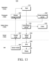
- FIG. 1 is a block diagram illustrating an electronic device 101 in a network environment 100 according to various embodiments.
- the electronic device 101 in the network environment 100 may communicate with an electronic device 102 via a first network 198 (e.g., a short-range wireless communication network), or at least one of an electronic device 104 or a server 108 via a second network 199 (e.g., a long-range wireless communication network).
- the electronic device 101 may communicate with the electronic device 104 via the server 108.
- the electronic device 101 may include a processor 120, memory 130, an input module 150, a sound output module 155, a display module 160, an audio module 170, a sensor module 176, an interface 177, a connecting terminal 178, a haptic module 179, a camera module 180, a power management module 188, a battery 189, a communication module 190, a subscriber identification module(SIM) 196, or an antenna module 197.
- at least one of the components e.g., the connecting terminal 178) may be omitted from the electronic device 101, or one or more other components may be added in the electronic device 101.
- some of the components e.g., the sensor module 176, the camera module 180, or the antenna module 197) may be implemented as a single component (e.g., the display module 160).
- the processor 120 may execute, for example, software (e.g., a program 140) to control at least one other component (e.g., a hardware or software component) of the electronic device 101 coupled with the processor 120, and may perform various data processing or computation.
- the processor 120 may store a command or data received from another component (e.g., the sensor module 176 or the communication module 190) in volatile memory 132, process the command or the data stored in the volatile memory 132, and store resulting data in non-volatile memory 134.
- the processor 120 may include a main processor 121 (e.g., a central processing unit (CPU) or an application processor (AP)), or an auxiliary processor 123 (e.g., a graphics processing unit (GPU), a neural processing unit (NPU), an image signal processor (ISP), a sensor hub processor, or a communication processor (CP)) that is operable independently from, or in conjunction with, the main processor 121.
- a main processor 121 e.g., a central processing unit (CPU) or an application processor (AP)
- auxiliary processor 123 e.g., a graphics processing unit (GPU), a neural processing unit (NPU), an image signal processor (ISP), a sensor hub processor, or a communication processor (CP)
- the main processor 121 may be adapted to consume less power than the main processor 121, or to be specific to a specified function.
- the auxiliary processor 123 may be implemented as separate from, or as part of the main processor 121.
- the auxiliary processor 123 may control at least some of functions or states related to at least one component (e.g., the display module 160, the sensor module 176, or the communication module 190) among the components of the electronic device 101, instead of the main processor 121 while the main processor 121 is in an inactive (e.g., sleep) state, or together with the main processor 121 while the main processor 121 is in an active state (e.g., executing an application).
- the auxiliary processor 123 e.g., an image signal processor or a communication processor
- the auxiliary processor 123 may include a hardware structure specified for artificial intelligence model processing.
- An artificial intelligence model may be generated by machine learning. Such learning may be performed, e.g., by the electronic device 101 where the artificial intelligence is performed or via a separate server (e.g., the server 108). Learning algorithms may include, but are not limited to, e.g., supervised learning, unsupervised learning, semi-supervised learning, or reinforcement learning.
- the artificial intelligence model may include a plurality of artificial neural network layers.
- the artificial neural network may be a deep neural network (DNN), a convolutional neural network (CNN), a recurrent neural network (RNN), a restricted boltzmann machine (RBM), a deep belief network (DBN), a bidirectional recurrent deep neural network (BRDNN), deep Q-network or a combination of two or more thereof but is not limited thereto.
- the artificial intelligence model may, additionally or alternatively, include a software structure other than the hardware structure.
- the memory 130 may store various data used by at least one component (e.g., the processor 120 or the sensor module 176) of the electronic device 101.
- the various data may include, for example, software (e.g., the program 140) and input data or output data for a command related thererto.
- the memory 130 may include the volatile memory 132 or the non-volatile memory 134.
- the program 140 may be stored in the memory 130 as software, and may include, for example, an operating system (OS) 142, middleware 144, or an application 146.
- OS operating system
- middleware middleware
- application application
- the input module 150 may receive a command or data to be used by another component (e.g., the processor 120) of the electronic device 101, from the outside (e.g., a user) of the electronic device 101.
- the input module 150 may include, for example, a microphone, a mouse, a keyboard, a key (e.g., a button), or a digital pen (e.g., a stylus pen).
- the sound output module 155 may output sound signals to the outside of the electronic device 101.
- the sound output module 155 may include, for example, a speaker or a receiver.
- the speaker may be used for general purposes, such as playing multimedia or playing record.
- the receiver may be used for receiving incoming calls. According to an embodiment, the receiver may be implemented as separate from, or as part of the speaker.
- the display module 160 may visually provide information to the outside (e.g., a user) of the electronic device 101.
- the display module 160 may include, for example, a display, a hologram device, or a projector and control circuitry to control a corresponding one of the display, hologram device, and projector.
- the display module 160 may include a touch sensor adapted to detect a touch, or a pressure sensor adapted to measure the intensity of force incurred by the touch.
- the audio module 170 may convert a sound into an electrical signal and vice versa. According to an embodiment, the audio module 170 may obtain the sound via the input module 150, or output the sound via the sound output module 155 or a headphone of an external electronic device (e.g., an electronic device 102) directly (e.g., wiredly) or wirelessly coupled with the electronic device 101.
- an external electronic device e.g., an electronic device 102
- directly e.g., wiredly
- wirelessly e.g., wirelessly
- the sensor module 176 may detect an operational state (e.g., power or temperature) of the electronic device 101 or an environmental state (e.g., a state of a user) external to the electronic device 101, and then generate an electrical signal or data value corresponding to the detected state.
- the sensor module 176 may include, for example, a gesture sensor, a gyro sensor, an atmospheric pressure sensor, a magnetic sensor, an acceleration sensor, a grip sensor, a proximity sensor, a color sensor, an infrared (IR) sensor, a biometric sensor, a temperature sensor, a humidity sensor, or an illuminance sensor.
- the interface 177 may support one or more specified protocols to be used for the electronic device 101 to be coupled with the external electronic device (e.g., the electronic device 102) directly (e.g., wiredly) or wirelessly.
- the interface 177 may include, for example, a high definition multimedia interface (HDMI), a universal serial bus (USB) interface, a secure digital (SD) card interface, or an audio interface.
- HDMI high definition multimedia interface
- USB universal serial bus
- SD secure digital
- a connecting terminal 178 may include a connector via which the electronic device 101 may be physically connected with the external electronic device (e.g., the electronic device 102).
- the connecting terminal 178 may include, for example, a HDMI connector, a USB connector, a SD card connector, or an audio connector (e.g., a headphone connector).
- the haptic module 179 may convert an electrical signal into a mechanical stimulus (e.g., a vibration or a movement) or electrical stimulus which may be recognized by a user via his tactile sensation or kinesthetic sensation.
- the haptic module 179 may include, for example, a motor, a piezoelectric element, or an electric stimulator.
- the camera module 180 may capture a still image or moving images.
- the camera module 180 may include one or more lenses, image sensors, image signal processors, or flashes.
- the power management module 188 may manage power supplied to the electronic device 101.
- the power management module 188 may be implemented as at least part of, for example, a power management integrated circuit (PMIC).
- PMIC power management integrated circuit
- the battery 189 may supply power to at least one component of the electronic device 101.
- the battery 189 may include, for example, a primary cell which is not rechargeable, a secondary cell which is rechargeable, or a fuel cell.
- the communication module 190 may support establishing a direct (e.g., wired) communication channel or a wireless communication channel between the electronic device 101 and the external electronic device (e.g., the electronic device 102, the electronic device 104, or the server 108) and performing communication via the established communication channel.
- the communication module 190 may include one or more communication processors that are operable independently from the processor 120 (e.g., the application processor (AP)) and supports a direct (e.g., wired) communication or a wireless communication.
- AP application processor
- the communication module 190 may include a wireless communication module 192 (e.g., a cellular communication module, a short-range wireless communication module, or a global navigation satellite system (GNSS) communication module) or a wired communication module 194 (e.g., a local area network (LAN) communication module or a power line communication (PLC) module).
- a wireless communication module 192 e.g., a cellular communication module, a short-range wireless communication module, or a global navigation satellite system (GNSS) communication module
- GNSS global navigation satellite system
- wired communication module 194 e.g., a local area network (LAN) communication module or a power line communication (PLC) module.
- LAN local area network
- PLC power line communication
- a corresponding one of these communication modules may communicate with the external electronic device via the first network 198 (e.g., a short-range communication network, such as Bluetooth TM , wireless-fidelity (Wi-Fi) direct, or infrared data association (IrDA)) or the second network 199 (e.g., a long-range communication network, such as a legacy cellular network, a 5G network, a next-generation communication network, the Internet, or a computer network (e.g., LAN or wide area network (WAN)).
- first network 198 e.g., a short-range communication network, such as Bluetooth TM , wireless-fidelity (Wi-Fi) direct, or infrared data association (IrDA)
- the second network 199 e.g., a long-range communication network, such as a legacy cellular network, a 5G network, a next-generation communication network, the Internet, or a computer network (e.g., LAN or wide area network (WAN)).
- the wireless communication module 192 may identify and authenticate the electronic device 101 in a communication network, such as the first network 198 or the second network 199, using subscriber information (e.g., international mobile subscriber identity (IMSI)) stored in the subscriber identification module 196.
- subscriber information e.g., international mobile subscriber identity (IMSI)
- the wireless communication module 192 may support a 5G network, after a 4G network, and next-generation communication technology, e.g., new radio (NR) access technology.
- the NR access technology may support enhanced mobile broadband (eMBB), massive machine type communications (mMTC), or ultra-reliable and low-latency communications (URLLC).
- eMBB enhanced mobile broadband
- mMTC massive machine type communications
- URLLC ultra-reliable and low-latency communications
- the wireless communication module 192 may support a high-frequency band (e.g., the mmWave band) to achieve, e.g., a high data transmission rate.
- the wireless communication module 192 may support various technologies for securing performance on a high-frequency band, such as, e.g., beamforming, massive multiple-input and multiple-output (massive MIMO), full dimensional MIMO (FD-MIMO), array antenna, analog beam-forming, or large scale antenna.
- the wireless communication module 192 may support various requirements specified in the electronic device 101, an external electronic device (e.g., the electronic device 104), or a network system (e.g., the second network 199).
- the wireless communication module 192 may support a peak data rate (e.g., 20Gbps or more) for implementing eMBB, loss coverage (e.g., 164dB or less) for implementing mMTC, or U-plane latency (e.g., 0.5ms or less for each of downlink (DL) and uplink (UL), or a round trip of 1ms or less) for implementing URLLC.
- a peak data rate e.g., 20Gbps or more
- loss coverage e.g., 164dB or less
- U-plane latency e.g., 0.5ms or less for each of downlink (DL) and uplink (UL), or a round trip of 1ms or less
- the antenna module 197 may transmit or receive a signal or power to or from the outside (e.g., the external electronic device) of the electronic device 101.
- the antenna module 197 may include an antenna including a radiating element composed of a conductive material or a conductive pattern formed in or on a substrate (e.g., a printed circuit board (PCB)).
- the antenna module 197 may include a plurality of antennas (e.g., array antennas). In such a case, at least one antenna appropriate for a communication scheme used in the communication network, such as the first network 198 or the second network 199, may be selected, for example, by the communication module 190 (e.g., the wireless communication module 192) from the plurality of antennas.
- the signal or the power may then be transmitted or received between the communication module 190 and the external electronic device via the selected at least one antenna.
- another component e.g., a radio frequency integrated circuit (RFIC)
- RFIC radio frequency integrated circuit
- the antenna module 197 may form a mmWave antenna module.
- the mmWave antenna module may include a printed circuit board, a RFIC disposed on a first surface (e.g., the bottom surface) of the printed circuit board, or adjacent to the first surface and capable of supporting a designated high-frequency band (e.g., the mmWave band), and a plurality of antennas (e.g., array antennas) disposed on a second surface (e.g., the top or a side surface) of the printed circuit board, or adjacent to the second surface and capable of transmitting or receiving signals of the designated high-frequency band.
- a RFIC disposed on a first surface (e.g., the bottom surface) of the printed circuit board, or adjacent to the first surface and capable of supporting a designated high-frequency band (e.g., the mmWave band)
- a plurality of antennas e.g., array antennas
- At least some of the above-described components may be coupled mutually and communicate signals (e.g., commands or data) therebetween via an inter-peripheral communication scheme (e.g., a bus, general purpose input and output (GPIO), serial peripheral interface (SPI), or mobile industry processor interface (MIPI)).
- an inter-peripheral communication scheme e.g., a bus, general purpose input and output (GPIO), serial peripheral interface (SPI), or mobile industry processor interface (MIPI)
- commands or data may be transmitted or received between the electronic device 101 and the external electronic device 104 via the server 108 coupled with the second network 199.
- Each of the electronic devices 102 or 104 may be a device of a same type as, or a different type, from the electronic device 101.
- all or some of operations to be executed at the electronic device 101 may be executed at one or more of the external electronic devices 102, 104, or 108. For example, if the electronic device 101 should perform a function or a service automatically, or in response to a request from a user or another device, the electronic device 101, instead of, or in addition to, executing the function or the service, may request the one or more external electronic devices to perform at least part of the function or the service.
- the one or more external electronic devices receiving the request may perform the at least part of the function or the service requested, or an additional function or an additional service related to the request, and transfer an outcome of the performing to the electronic device 101.
- the electronic device 101 may provide the outcome, with or without further processing of the outcome, as at least part of a reply to the request.
- a cloud computing, distributed computing, mobile edge computing (MEC), or client-server computing technology may be used, for example.
- the electronic device 101 may provide ultra low-latency services using, e.g., distributed computing or mobile edge computing.
- the external electronic device 104 may include an internet-of-things (IoT) device.
- the server 108 may be an intelligent server using machine learning and/or a neural network.
- the external electronic device 104 or the server 108 may be included in the second network 199.
- the electronic device 101 may be applied to intelligent services (e.g., smart home, smart city, smart car, or healthcare) based on 5G communication technology or IoT-related technology.
- the electronic device 101 may include the processor 120, the memory 130, the display module 160, and the sensor module 176, and perform a screen recording operation according to extension or contraction of an exposed area (e.g., a visible area) of a flexible display included in the display module 160.
- the processor 120, the memory 130, the display module 160, and the sensor module 176 included in the electronic device 101 may be electrically and/or operatively coupled to each other to exchange signals (e.g., commands or data) with each other.
- the sensor module 176 may include at least one sensor for detecting movement (e.g., sliding, folding, unfolding, or rolling) according to extension or contraction of the flexible display.
- the main components of an electronic device have been described in the context of the electronic device 101 of FIG. 1 in an embodiment.
- all of the components illustrated in FIG. 1 are not essential, and the electronic device 101 may be implemented with more or fewer components than the illustrated ones.
- the positions of the main components of the electronic device 101 described above with reference to FIG. 1 may be changed according to an embodiment.
- FIG. 2A is a front perspective view illustrating an electronic device in a sliding-in state according to an embodiment
- FIG. 2B is a front perspective view illustrating the electronic device in a sliding-out state according to an embodiment.
- the electronic device 101 may include the display module 160 (e.g., the display module 160 of FIG. 1 ) that includes, as hardware components, a housing 210, a display 220 disposed to expose some of a plurality of areas on a front surface 201 outside the housing 210, and a display driving module (not shown) for moving the display 220 to exposesome of the plurality of areas, the term "expose” as used herein includes "make visible” and is intended to include a situation in which the display includes a cover layer, cover glass or other protective layer.
- the display 220 may be configured as a flexible display or include a flexible display.
- the electronic device 101 may include, as a software component, at least one processor (e.g., the processor 120 of FIG. 1 ) that controls driving of the hardware components and performs operations or functions for changing (or moving) the exposed area (e.g., a visible area) of the display 220.
- processor e.g., the processor 120 of FIG. 1
- the exposed area e.g., a visible area
- the housing 210 may be disposed on the front surface 201, surrounding at least part of the periphery of the display 220.
- the housing 210 may form a partial area of the front surface, a side surface, and a rear surface of the electronic device 101.
- the housing 210 may form a partial area of the side surface and a partial area of the rear surface of the electronic device 101.
- the housing 210 may include a first housing 211 and a second housing 213.
- the second housing 213 may be coupled with the first housing 211 to be slidable relative to the first housing 211.
- the second housing 213 may slide in or slide out along a latitudinal direction (contraction or extension direction).
- a driving source for the sliding operation of the second housing 213 may be driven manually, automatically, or semi-automatically.
- a sliding guide member or a sliding driver e.g., a motor
- a roller-type guide member or a roller driver e.g., a motor
- the driving source is not necessarily limited to the sliding type or the roller type.
- a second area 223 of the display 220 may be withdrawn from the inside of the electronic device 101.
- the electronic device 101 is switched from the sliding-out state to the sliding-in state according to a sliding operation of the second housing 213, the second area 223 of the display 220 may be inserted into the electronic device 101.
- the size of an area exposed by sliding-in or sliding-out of the display 220 by the display driving module (hereinafter, referred to as an exposed area) is decreased or increased, the size of the exposed area may be changed.
- the display 220 may be disposed such that some area (e.g., a first area 221) configured as a main use area among a plurality of display areas of the display 220 is visually exposed from the front surface 201 of the housing 210 in the sliding-in state.
- the display 220 may be configured such that the first area 221 among the plurality of display areas of the display 220 moves in a movement direction (e.g., a first direction 202) and slides to another exposure position of the front surface 201 by driving of the display driving module (not shown).
- the second area 223 extending from another area (e.g., the first area 221) of the display 220 may be exposed, thereby extending the exposed area.
- the display 220 may be moved in the first direction 202 by the display driving module (not shown).
- the first area 221 exposed on the front surface 201 may be used as a main use area, and the second area 223 exposed on the front surface 201 is a sub-use area (e.g., a dummy area).
- some of the plurality of areas may be accommodated inside the housing 210 without being exposed on the front surface 201, and thus may not be used.
- the display driving module may be driven under the control of the at least one processor 120, and include a roller-type rotation member (not shown) disposed inside the housing 210 and rotating to move the display 220, and a motor (not shown) driving the rotation member (not shown).
- the display 220 may be coupled with the front surface of the second housing 213 and slide together with the second housing 213. Sliding of the second housing 213 may be understood as sliding of the display 220.
- the display 220 may be configured to change (e.g., increase/decrease) the size of a screen exposed on the front surface 201 of the electronic device 101 based on the sliding operation of the second housing 213.
- the second housing 213 slides out along the first direction 202
- the second area 223 of the display 220 may be withdrawn to the outside of the electronic device 101 to increase the screen size of the exposed area of the display 220.
- the second area 223 of the display 220 may be inserted into the electronic device 101 to decrease the screen size of the exposed area of the display 220.
- the display 220 may move in the first direction 202 by a specified distance according to a sliding operation.
- the screen size of the area of the display 220 exposed to the outside of the electronic device 101 may be changed (increased or decreased) by the sliding operation.
- a screen of the display 220 exposed on the front surface 201 of the electronic device 101 may correspond to the first area 221.
- a screen of the display 220 exposed on the front surface 201 of the electronic device 101 may correspond to the first area 221 and the second area 223.
- the display 220 may move along the first direction 202 by a specified distance (e.g., an extension distance) by the sliding operation of the second housing 213 with respect to the first housing 211.
- the screen size of the display 220 may be variable (increased or decreased) in response to the sliding distance.
- the electronic device 101 may detect a change in the screen size of the exposed area of the display 220 through at least one sensor (e.g., the sensor module 140). For example, the electronic device 101 may detect a sliding distance of the display 220 through the at least one sensor, and detect a change in the screen size of the exposed area of the display 220 based on the detected sliding distance. The electronic device 101 may obtain a sensing value according to the movement of the display 220.
- the electronic device 101 may detect movement (e.g., rotation) of a rotation structure (not shown, e.g., a hinge) in the first housing 211 through the at least one sensor (e.g., the sensor module 140), and determine whether the second housing 213 has been inserted into or withdrawn from the first housing 211.
- the electronic device 101 may detect sliding of the display 220 using a distance sensor.
- the distance sensor may measure a movement distance of the second housing 213.
- the distance sensor may include at least one of a time of flight (TOF) sensor, an ultrasonic sensor, or a radio wave sensor.
- TOF time of flight
- the electronic device 101 may detect a sliding distance of the second housing 213 with respect to the first housing 211 through the distance sensor.
- the electronic device 101 may detect the sliding distance using at least one sensor.
- the at least one sensor may be configured to generate electrical signals that are distinguished from each other in different states (e.g., the sliding-in state and the sliding-out state) in which the degrees of movement of the second housing 213 are different.
- the at least one sensor may include a Hall sensor and/or a magnet sensor.
- the electronic device 101 may detect a sliding distance through at least one sensor.
- the electronic device 101 may detect a change in the screen size of the display 220 based on a sensing value according to movement of the display 220.
- the electronic device 101 may detect screen rotation of the display 220 according to rotation of the electronic device 101 through at least one sensor.
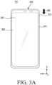
- FIG. 3A is a plan view illustrating an electronic device in the sliding-in state according to an embodiment
- FIG. 3B is a plan view illustrating the electronic device in the sliding-out state according to an embodiment.
- the electronic device 101 which is a vertically slidable electronic device, may include a display 320 in which an exposed area is vertically extendable.
- a housing 310 may include a first housing 311 and a second housing 313.
- the display 320 may include a first area 321 and a second area 323.
- the second housing 313 may slide into the first housing 311 to be inserted into the first housing 311.
- the second housing 313 may slide out from the first housing 311 to be withdrawn from the first housing 311.
- a sliding driving source of the second housing 313 may be driven manually, automatically, or semi-automatically.
- the second housing 313 may slide into or slid out from the first housing 311 by a guide member.
- the second housing 313 may slide in (e.g., in direction 304) or slide out (e.g., in direction 302) along a longitudinal direction (e.g., Y-axis direction) of the first housing 311.
- the second housing 313 may include the display 320 having a flexible structure disposed on a front surface.
- the display 320 may be configured to change (e.g., increase/decrease) the size of a screen exposed on the front surface of the electronic device 101 based on a sliding operation of the second housing 313. According to the sliding-out operation, the size of a screen of the display 320 exposed on the front surface of the electronic device 101 may be increased. According to the sliding-in operation, the size of a screen of the display 320 exposed on the front surface of the electronic device 300 may be decreased.
- the screen of the display 320 exposed on the front surface of the electronic device 300 may include the first area 321.
- the screen of the display 320 exposed on the front surface of the electronic device 101 may include the first area 321 and the second area 323.
- Part of the display 320 may be inserted into or withdrawn from the first housing 311 by a guide member.
- the display 320 may include the first area 321 that is always exposed, and the second area 323 that is selectively exposed according to a sliding operation.
- the second area 323 may be inserted into the electronic device 101 according to the sliding-in operation of the second housing 313 or withdrawn from the electronic device 101 according to the sliding-out operation of the second housing 313.
- the second area 323 may be a screen area extended according to sliding-out of the second housing 313.
- FIG. 4 is a diagram illustrating examples of screen recording in an electronic device according to an embodiment.
- a processor e.g., the processor 120 of FIG. 1
- an electronic device e.g., the electronic device 101 of FIGS. 1 and 2
- the processor 120 may record the screen of the display 220 based on a reference screen size.
- the reference screen size may be a screen size of a maximum exposed area based on maximum extension of the display 220.
- the processor 120 may detect, through at least one sensor in the sensor module 140, whether the screen size of the exposed area of the display 220 has been changed during the screen recording.
- the processor 120 may record the screen of the exposed area in the reference screen size during the screen recording.
- the size of the screen (e.g., a first screen) of the exposed area is smaller than the reference screen size, and thus a dummy area may be included as a blank area or an area processed in black in a recorded image.
- the processor 120 may identify a change in the size of the exposed area from a recording start time to a recording end time.
- the processor 120 may store a recorded image 430 of the reference screen size, obtained during the screen recording.
- the processor 120 may store the recorded image 430 of the reference screen size.
- FIG. 4(a) when the sliding-in state at the start of screen recording is switched to the sliding-out state during recording of a screen of an exposed area 410, a screen of an exposed area 420 is recorded, and then the screen recording is completed, the processor 120 may store the recorded image 430 of the reference screen size. As illustrated in FIG.
- the processor 120 may store the recorded image 430 of the reference screen size.
- the processor 120 records the screen of the exposed area 420.
- the processor 120 records the screen of the exposed area 410.
- the processor 120 may store the recorded image 430 of the reference screen size.
- the processor 120 may generate an image including an object to which a visual effect is applied in a dummy area of a recorded image, and store the generated image as a final recorded image.
- the processor 120 may generate the object to which the visual effect is applied in response to a display extension (e.g., sliding-out) request or a display contraction (e.g., sliding-in) request during screen recording.
- the processor 120 may control the display module 160 to display the object to which the visual effect is applied in the other area (e.g., part of the exposed area corresponding to the dummy area) in which a first screen is not displayed.
- the processor 120 may record, in the reference screen size, the first screen displayed in the exposed area and the object to which the visual effect is applied. Upon completion of the change of the screen size of the exposed area, the processor 120 may control the display module 160 to display a contracted screen or an extended screen without displaying the object to which the visual effect is applied, and record the contracted screen or the extended screen displayed in the exposed area.
- the processor 120 may generate a recorded image (440) of a fixed screen size by cropping the dummy area in an image obtained during screen recording, and store the generated recorded image (440) as a final recorded image.
- the dummy area may be a blank area or an area processed in black in the recorded image, corresponding to a hidden area (e.g., the second area 223 of FIG. 2 or the second area 323 of FIG. 3B ) not exposed in the sliding-in state.
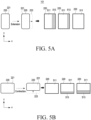
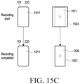
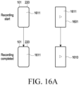
- FIGS. 5A, 5B , and 5C are diagrams illustrating examples of screen recording in an electronic device according to an embodiment.
- an exposed area may extend in the first direction to gradually expose the hidden second area 223. Therefore, the exposed area may include both of the first area 221 and the second area 223.
- the processor 120 may display a screen (e.g., the first screen) 511 including at least one content, while gradually (e.g., at a specified rate or speed) extending the screen 511.
- the processor 120 may display an object to which a visual effect is applied in a part 513 of the exposed area, corresponding to a dummy area of a recorded image.
- the processor 120 may display the object to which the visual effect is applied, while gradually changing the object during the sliding-out operation.
- the processor 120 may control the display module 160 to display the screen 511 extended to the maximum screen size of the exposed area.
- the exposed area may be contracted in the second direction to gradually contract the second area 223. Therefore, the exposed area may be contracted.
- the processor 120 may display the screen (e.g., the first screen) 511 including at least one content, while gradually contracting the screen 511.
- the processor 120 may display an object to which a visual effect is applied in the part 513 of the exposed area, corresponding to the dummy area of the recorded image. For example, the processor 120 may gradually display the object to which the visual effect is applied, while gradually changing the object during the sliding-in operation. When the sliding-in operation is completed, the processor 120 may control the display module 160 to display the screen 511 contracted to the screen size of the first area 221 in the exposed area.
- the screen 511 of the first area to be recorded may gradually move according to the rotation. Accordingly, the position of the part 513 (parts 513a and 513b) of the exposed area corresponding to the dummy area of the recorded image may be changed.
- the processor 120 may display an object with a visual effect applied to the part 513 of the exposed area corresponding to the dummy area of the recorded image.
- the processor 120 may identify the dummy area corresponding to the difference between the screen size of the exposed area and the reference screen size in the recorded image during screen recording, and generate an animation related to at least one content included in the screen of the exposed area.
- the processor 120 may store a final recorded image in the memory 130 by including the generated animation in the dummy area of the recorded image.
- the processor 120 may control the display module 160 to display the generated animation in the dummy area, and record both of the screen displayed in the exposed area and the animation displayed in the dummy area.
- the processor 120 may control the display module 160 to display the extended screen in the extended exposed area. For example, as the exposed area is gradually extended, the processor 120 may identify that the dummy area is gradually contracted, and control the display module 160 to display the animation that is gradually contracted in response to the contraction of the dummy area.
- the processor 120 may display the animation in a dummy area having a fixed size corresponding to the exposed second area 223, and after the specified time elapses (e.g., the extension of the exposed area is completed), control the display module 160 to display the extended screen on the entire exposed area including the first area 221 and the second area 223.
- the specified time elapses e.g., the extension of the exposed area is completed
- the processor 120 may control the display module 160 to display the generated object to which the visual effect is applied in the dummy area, record both of the screen displayed in the exposed area and the object to which the visual effect is applied, and store the recorded image as a final recorded image.
- the processor 120 may control the display module 160 to display the object to which a visual effect of gradual contraction is applied in the dummy area, in response to the gradual contraction of the exposed area.
- the processor 120 may control the display module 160 to display the object to which the visual effect is applied in the dummy area of a fixed size corresponding to the second area 223, and upon elapse of a specified time (e.g., completion of the contraction of the exposed area), to display the contracted screen in the exposed area including the first area 221.
- a specified time e.g., completion of the contraction of the exposed area
- the processor 120 may generate a final recorded image by including (or synthesizing) an image that has recorded the screen of the first area 221 and the dummy area of the recorded image corresponding to the hidden second area 223, and store the generated final recorded image in the memory 130.
- the processor 120 may generate the object to which the visual effect is applied, based on at least one content included in the screen (e.g., the first screen) of the first area 221 and/or another content displayed in the second area 223 before the sliding-in operation, and may be generated by applying the visual effect.
- the object to which the visual effect is applied may include, for example, at least one of an animation, a preview image, a still image, a dynamic image, a thumbnail, or a graphic.
- the visual effect may include at least one of, for example, a sharpness (sharpen, blur, or dim) effect, a brightness/contrast effect, a fade in/out effect, a black in/out effect, a disappearing effect, an appearing effect, a transparency effect, a decorative effect, or a cue.
- the processor 120 may differently generate an object to which a visual effect is applied according to the type of at least one content displayed in an exposed area.
- the processor 120 may differently generate an object to which a visual effect is applied according to a change in the display position of the first screen 511.
- the processor 120 may store information about a screen size change of the display 120 during recording, together with a recorded image.
- the stored information about the screen size change may be used to reproduce the recorded image.
- a screen ratio may be changed in response to the change of the screen size of the display 120.
- the processor 120 may record the screen of the display 120 based on the reference screen size and a reference screen ratio.
- the processor 120 may reproduce the stored final recorded image, and display the reproduced image on the display 120.
- the processor 120 may reproduce the recorded image, while maintaining the current screen size and the size of the recorded image.
- the image may be displayed such that the center of the image is located in the middle of the current screen of the display 120, or the recorded image may be displayed scaled to correspond to the current screen size.
- the processor 120 may detect a change in the screen size of the display 220 through at least one sensor in the sensor module 176 during the image reproduction.
- the processor 120 may reproduce and display the recorded image based on the changed screen size of the display 220 and the size of the recorded image.
- the recorded image may be displayed so that the size change of the area corresponding to the screen is recognizable while the screen size of the display 220 is fixed.
- the processor 120 may reproduce the recorded image including the screen image and the object to which the visual effect is applied, included in the dummy area.
- a “screen” may be understood as a physical screen of the electronic device 100 or the display 120 or a virtual screen displayed through the physical screen.
- a “screen size” may be understood as a size-related property of a screen.
- the screen size may be at least one of a screen width (horizontal), a screen height (vertical), a screen width and height, or a screen ratio (aspect ratio).
- the "size of an image (or an image frame)” may be understood as a size-related property of an image (or an image frame).
- the size of the image may be at least one of an image width (horizontal), an image height (vertical), the width and height of the image, or an image ratio (aspect ratio).
- a change in the size (e.g., width and height) of a screen or image may be linked to a change in the ratio of the screen or image.
- the ratio of the screen or image may be changed depending on the size of the screen or image. For example, when the size of the screen is changed by screen extension or contraction, the ratio (e.g., aspect ratio) of the screen may be changed to correspond to the size of the screen.
- the size of an image recording the screen may be changed according to a change in the size of the screen.
- the ratio of the image may be changed in response to the change in the size of the image.
- the electronic device 101 may have the same mechanical structure as the electronic device 101 of FIGS. 2A and 2B or the electronic device 101 of FIGS. 3A and 3B , and the structures illustrated in FIGS. 2A , 2B , 3A , and FIG. 3B are for illustrative purposes only, not limiting the scope of the embodiments.
- An embodiment is possible by modifying, changing, applying, and extending the structures within the scope including a display having a flexible structure (e.g., the display 220 of FIG. 1 ).
- an electronic device may include any one of a horizontally slidable electronic device, a vertical slidable electronic device, a multi-axis slidable electronic device that may slide in both directions (e.g., horizontal or vertical) about multiple axes, and a rollable electronic device in which substantially the entirety of the display (e.g., 90% or more of the total area) slides in one direction to roll on a rotation body in a housing or is withdrawn to be unfolded outside the housing.
- a horizontally slidable electronic device e.g., a vertical slidable electronic device
- a multi-axis slidable electronic device that may slide in both directions (e.g., horizontal or vertical) about multiple axes
- a rollable electronic device in which substantially the entirety of the display (e.g., 90% or more of the total area) slides in one direction to roll on a rotation body in a housing or is withdrawn to be unfolded outside the housing.
- an electronic device may include memory (e.g., the memory 130 of FIG. 1 ), a display module (e.g., the display module 160 of FIG. 1 ) including a flexible display, and at least one processor (e.g., the processor 120 of FIG. 1 ) electrically coupled to the memory and the display module.
- memory e.g., the memory 130 of FIG. 1
- display module e.g., the display module 160 of FIG. 1
- at least one processor e.g., the processor 120 of FIG. 1
- the at least one processor may be configured to record a screen of the display displayed in an exposed area of the display in a reference screen size, based on a screen size of the exposed area being changed by extension or contraction of the exposed area of the display during the recording, control the display module to display an object to which a visual effect related to at least one content displayed on the screen is applied, in part of the exposed area corresponding to the changed size, and in response to completion of the extension or contraction of the exposed area of the display during the recording, control the display module to display an extended or contracted screen in an extended exposed area or a contracted exposed area.
- Other embodiments are available.
- the reference screen size may be a screen size of a maximum exposed area based on maximum extension of the display.
- the at least one processor may be configured to, based on the absence of a change in the screen size based on the extension or contraction of the exposed area of the display from a recording start time to a recording end time, store a recorded image recorded from the recording start time to the recording end time in an output size corresponding to the screen size of the exposed area.
- the at least one processor may be configured to, based on the presence of a change in a size of the exposed area from the recording start time to the recording end time, store the recorded image recorded from the recording start time to the recording end time in the reference screen size.
- the at least one processor may be configured to, when the exposed area of the display is extended during the screen recording, control the display module to gradually extend the screen in response to the extension of the exposed area, and control the display module to display the object to which the visual effect is applied in the part of the exposed area, while making the object gradually larger in response to the extension of the exposed area.
- the extended screen may include a first screen including the at least one content or a second screen including the first screen and another content.
- the at least one processor may be configured to when the exposed area of the display is contracted during the screen recording, control the display module to gradually contract the screen in response to the contraction of the exposed area, and control the display module to display the object to which the visual effect is applied in the part of the exposed area, while making the object gradually smaller in response to the contraction of the exposed area.
- the electronic device may further include a sensor module including at least one sensor electrically coupled to the at least one processor, and the at least one processor may be configured to when the sensor module detects that a size of the exposed area is equal to or greater than the reference screen size during the screen recording, obtain a first partial recorded image of the screen displayed in the exposed area, when the sensor module detects that the size of the exposed area is less than the reference screen size during the screen recording, identify contraction of the exposed area based on a first direction, and generate the object to which the visual effect is applied, based on at least one content included in the screen, obtain a second partial recorded image of the contracted screen and the object to which the visual effect is applied, and upon completion of the screen recording, store a final recorded image including the first partial recorded image and the second partial recorded image in the memory.
- a sensor module including at least one sensor electrically coupled to the at least one processor
- the at least one processor may be configured to when the sensor module detects that a size of the exposed area is equal to or greater than the reference screen size during the screen recording
- the electronic device may further include a sensor module including at least one sensor electrically coupled to the at least one processor, and the at least one processor may be configured to when the sensor module detects that a size of the exposed area is equal to or greater than a size of a first screen and less than the reference screen size during the screen recording, identify extension of the exposed area based on a second direction, generate an object to which a visual effect related to at least one content included in the screen is applied, and obtain a third recorded image of the extended screen and the object to which the visual effect is applied in the extended exposed area, when the sensor module detects that the size of the exposed area is equal to or greater than the reference screen size during the screen recording, obtain a fourth recoded image of the extended screen displayed in the extended exposed area, and upon completion of the screen recording, store a final recorded image including the third recorded image and the fourth recorded image in the memory.
- a sensor module including at least one sensor electrically coupled to the at least one processor
- the at least one processor may be configured to when the sensor module detects that a
- the at least one processor may be configured to, after the contraction of the exposed area of the display is completed during the recording, store a final recorded image by synthesizing the object to which the visual effect is applied in a dummy area in a recorded image of a screen displayed in the contracted exposed area, in the memory.
- the object to which the visual effect is applied may be generated based on the at least one content displayed on the screen or another content configured in a hidden area, and a different visual effect is applied according to a displayed position and characteristic of a first screen including the at least one content.
- the at least one processor may be configured to, based on the display being in a contracted state at a recording start time, record the screen in both the reference screen size and a screen size of the contracted state, based on the absence of a change in the screen size of the exposed area from the recording start time to a recording end time, store a first recorded image recorded in the screen size of the contracted state at the recording start time and until the recording end time and delete a second recorded image recorded in the reference screen size at the recording start time and until the recording end time, and based on the screen size of the exposed area being increased during the recording, discontinue the recording in the screen size of the contracted state and store the second recorded image recorded in the reference screen size at the recording start time and until the recording end time.
- the at least one processor may be configured to, based on the display being in a contracted state at a recording start time, record the screen in a screen size of the contracted state without recording in the reference screen size, based on the absence of a change in the screen size of the exposed area from the recording start time to a recording end time, store a first recorded image recorded in the screen size of the contracted state at the recording start time and until the recording end time, and based on the screen size of the exposed area being changed during the recording, store the first recorded image recorded in the screen size of the contracted state from the recording start time, record the screen in the reference screen size instead of the screen size of the contracted state until the recording end time or a next change time of the screen size, and store a second recorded image recorded in the reference screen size.
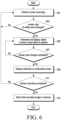
- FIG. 6 is a diagram illustrating an exemplary method of operating an electronic device according to an embodiment
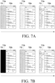
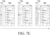
- FIGS. 7A to 7E are diagrams illustrating examples of screen recording in an electronic device according to an embodiment.
- an electronic device may perform screen recording to record a screen displayed in an exposed area of a display (e.g., the display 220 of FIGS. 2A and 2B or the display 320 of FIGS. 3A and 3B ) in response to a screen recording request in operation 601.
- the electronic device may store a screen image that is a recording of a screen displayed in the exposed area in memory (e.g., the memory 130 of FIG. 1 ).
- the electronic device may record the screen displayed in the exposed area of the display in a reference screen size.
- the reference screen size may be a screen size of a maximum exposed area based on maximum extension of the display.
- the electronic device may identify a screen recording start time, a screen size of the display, or a state (e.g., the sliding-in state or the sliding-out state) of the display.
- the electronic device may identify a contracted exposed area (e.g., the first area 221 of FIGS. 2A and 2B ) and a hidden area (e.g., the second area 223 of FIG. 2B ).
- the electronic device may record a screen including at least one content displayed in the contracted exposed area, together with a dummy area corresponding to an area (e.g., the hidden area) corresponding to a difference between the reference screen size and the screen size of the exposed area.
- the dummy area may correspond to the difference between the screen size of the exposed area and the reference screen size, and may be a blank area in which content is not displayed or an area processed in black in the obtained recorded image.
- the electronic device may identify an extended exposed area (e.g., the second area 223 of FIG. 2B ).
- the electronic device may record a screen including at least one content displayed in the extended exposed area.
- the electronic device may use at least one sensor (e.g., the sensor module 140) to identify whether the screen size of the exposed area of the display has been changed due to extension or contraction of the exposed area of the display during the screen recording.
- the electronic device may perform operation 605, and when the screen size of the exposed area has not been changed, the electronic device may perform operation 601.
- the electronic device may generate an object to which a visual effect (e.g., at least one of an animation, a preview image, a still image, a dynamic image, a thumbnail, or a graphic) related to at least one content included in the screen of the exposed area is applied, based on a change in the screen size of the exposed area due to extension or contraction of the exposed area of the display during the screen recording.
- the electronic device may identify the dummy area and display the object to which the visual effect is applied in at least part of the dummy area corresponding to the changed size.
- the visual effect may include at least one of, for example, a sharpness (sharpen, blur or dim) effect, a brightness/contrast effect, a fade in/out effect, a black in/out effect, a disappearing effect, an appearing effect, a transparency effect, a decorative effect, or a cue.
- the electronic device may store the recorded image in the memory by including the object to which the visual effect is applied in the dummy area of the recorded image, and display the object to which the visual effect is applied in part (e.g., part of the second area) of the exposed area of the display, corresponding to the dummy area. For example, as illustrated in FIG.
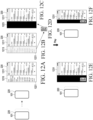
- the electronic device may display and store a recorded image 730a including an object 713a to which the fade in/out effect is applied in a dummy area 710.
- the electronic device may display and store a recorded image 730b including an object 713b to which the black in/out effect is applied in the dummy area 710.
- the electronic device may display and store a recorded image 730c including an object 713c to which a sharpen, blur, or dim effect is applied in the dummy area 710.
- FIG. 7A the electronic device may display and store a recorded image 730a including an object 713a to which the fade in/out effect is applied in a dummy area 710.
- the electronic device may display and store a recorded image 730b including an object 713b to which the black in/out effect is applied in the dummy area 710.
- the electronic device may display and store a recorded image 730c including an object 713c to which a sharpen, blur, or dim effect is applied in the dummy area 710.
- the electronic device may display and store a recorded image 730d including an object 713d to which the preview image effect is applied in the dummy area 710.
- the electronic device may display and store a recorded image 730e including an object 713e to which the cue effect is applied in the dummy area 710.
- the electronic device may display the object to which the visual effect is applied in an area (e.g., part of the second area) that is gradually exposed or hidden by the extension or contraction, while gradually exposing or hiding the object.
- the electronic device may identify whether the screen size change according to the extension or contraction of the exposed area of the display has been completed during the screen recording. As a result of the identification, when the screen size change has been completed, the electronic device performs operation 609. When the screen size change is not completed, the electronic device may continuously display the object to which the visual effect is applied in operation 605.
- the electronic device may display an extended or contracted screen on the extended or contracted exposed area in response to the extension or contraction of the exposed area.
- the electronic device may identify whether the screen recording has been completed. As a result of the identification, when the screen recording has been completed, the electronic device may perform operation 613, otherwise, the electronic device may continue to perform the screen recording operation in operation 601.
- the electronic device may store a final recorded image including the recorded screen image in the memory based on whether the screen size of the exposed area has been changed.
- the electronic device may identify a screen recording end time, and identify whether the screen size of the exposed area of the display has been changed from a recording start time to the recording end time.
- the electronic device may store, in the memory, a final recorded image including the screen image being a recording of the screen displayed on the exposed area and the object to which the visual effect is applied.
- the electronic device may store the screen image being a recording of the screen displayed on the exposed area as a recorded image in the memory. For example, when the screen size is fixed without a change in the screen size of the exposed area of the display from the recording start time to the recording end time, and the display state is the sliding-in state, the electronic device may crop the dummy area from the screen image recorded in the reference screen size, and store a screen image corresponding to the screen size of the exposed area as a recorded image.
- the exposed area corresponds to the reference screen size. Accordingly, the recorded screen image may be stored as a recorded image.
- FIG. 8 is a diagram illustrating an example of screen recording of an electronic device according to various embodiments
- FIGS. 9A and 9B are diagrams illustrating an example of screen recording of an electronic device according to various embodiments.
- the electronic device may differently display an object to which a visual effect is applied in part (e.g., a part of the second area) of an exposed area, corresponding to a dummy area based on the type of content included in a screen displayed on the exposed area.
- the electronic device 101 when performing operation 605 illustrated in FIG. 6 , may identify the type of content included in a screen displayed on the exposed area, or identify whether a new user interface (UI) has been configured, which is related to content (hereinafter referred to as first content) included in a screen 811 displayed on the display 220 (e.g., the display 220 of FIG. 1 ) or another content (hereinafter referred to as second content).
- first content content included in a screen 811 displayed on the display 220
- second content another content
- the electronic device 101 may generate objects 813a and 813b to which a visual effect is applied, based on the first content displayed on a current screen, and display the generated objects 813a and 813b in parts 821a and 821b of an extended exposed area corresponding to a dummy area.
- the electronic device 101 may display the screen 811 including the first content in the first area (e.g., the first area 221 of FIGS. 2A and 2B ) of the display 220 in the slid-in state (e.g., the contracted state).
- the electronic device 101 may store a recorded image in a reference screen size by including the dummy area corresponding to a hidden area (e.g., the second area 223 of FIG. 2B ), while recording a screen image of the screen 811 displayed in an exposed area.
- the electronic device 101 may display the screen 811 including the first content at the center of an extended exposed area.
- the disclosure is not limited thereto, and the electronic device 101 may display the screen 811 by arranging it on a side (a left, right, upper, or lower side).
- the electronic device 101 may store a recorded image in the reference screen size by including the dummy area corresponding to a hidden area (e.g., the second area 223) while recording the screen image of the screen 811 displayed in the exposed area.
- the electronic device 101 may designate the remaining area (e.g., left and right areas or upper and lower areas) of the extended exposed area except for the area in which the screen 811 is displayed, as part of the exposed area corresponding to the dummy area, and display the objects 813a and 813b to which a visual effect is applied in the designated part 821a and 821b of the exposed area.
- the electronic device 101 may record a screen image including the screen 811 and the displayed objects 813a and 813b to which the visual effect is applied, from a time of requesting extension of the exposed area of the display 220 to a time of completion of the extension of the exposed area or during a specified time.
- the electronic device 101 may store a recorded image by synthesizing the objects 813a and 813b to which the visual effect is applied in the dummy area corresponding to the remaining area except for the screen 811 in an image recorded in the reference screen size, without displaying the objects 813a and 813b to which the visual effect is applied in the designated part 821a and 821b of the exposed area, from the time of requesting extension of the exposed area of the display 220 to the time of completion of the extension of the exposed area or during the specified time.
- the electronic device 101 may display an extended screen 911 including the first content in a size corresponding to the screen size of an extended exposed area of the display 220.
- the electronic device 101 may store a screen image being a recording of the extended screen 911 displayed in the extended exposed area as a recorded image.
- the electronic device 101 may store recorded images recorded from a recording start time to a recording end time as a final recorded image.
- the electronic device 101 may display the screen 911 in a size corresponding to the screen size of an extended exposed area in the sliding-out state (e.g., the extended state) of the display 220.
- the electronic device 101 may store a screen image being a recording of the screen 911 displayed in the extended exposed area as a recorded image.
- the electronic device 101 may contract the current extended screen 911 including a first content and display the contracted screen 811 at the center of the extended exposed area, in response to a request for contraction of the exposed area of the display 220.
- the disclosure is not limited thereto, and the electronic device 101 may display the screen 811 in a side (the left, right, upper, or lower side).
- the electronic device 101 may designate the remaining area (e.g., the left and right areas or the upper and lower areas) of the extended exposed area except for the area in which the contracted screen 811 is displayed, as the part 821a and 821b of the exposed area corresponding to the dummy area, and display the objects 813a and 813b to which a visual effect is applied in the designated part 821a and 821b of the exposed area.
- the remaining area e.g., the left and right areas or the upper and lower areas
- the electronic device 101 may generate a final recorded image by synthesizing the objects 813a and 813b to which the visual effect is applied in the dummy area corresponding to the remaining area except for the screen 811 in an image recorded in a reference screen size, without displaying the objects 813a and 813b to which the visual effect is applied in the designated part 821a and 821b of the exposed area, from a time of requesting contraction of the exposed area to a time of completion of the contraction of the exposed area or during a specified time.
- the electronic device 101 may display the contracted screen 811 including the first content in a size corresponding to the screen size of a contracted exposed area of the display 220.
- the electronic device 101 may store a recorded image in the reference screen size by including the dummy area corresponding to a hidden area (e.g., the second area 223) while recording a screen image of the contracted screen 811 displayed in the exposed area.
- the electronic device 101 may store recorded images recorded from a recording start time to a recording end time as a final recorded image.
- FIG. 10 is a diagram illustrating an example of screen recording of an electronic device according to an embodiment
- FIGS. 11A and 11B are diagrams illustrating examples of screen recording of an electronic device according to an embodiment.
- the electronic device 101 when performing operation 605 illustrated in FIG. 6 , may identify the type of content included in a screen displayed on an exposed area, or identify whether a new UI has been configured, which is related to content (hereinafter referred to as first content) included in a first screen 1011 displayed on the display 220 (e.g., the display 220 of FIG. 1 ) or another content (hereinafter referred to as second content).
- first content content
- second content another content
- the electronic device 101 may generate an objects 1013 to which a visual effect is applied, based on the first content displayed on the first screen 1011 and/or another content (e.g., the second content) included in the new UI, and display the generated object 1013 to which the visual effect is applied in part 1021 of an extended exposed area corresponding to a dummy area of a recorded image. While the part 1021 of the exposed area in which the object 1013 to which the visual effect is applied has been described in the context of an area corresponding to the second area (e.g., the second area 223 of FIG.
- the disclosure is not limited thereto, and the part 1021 may be changed to a partial area of the first area (e.g., the first area 221 of FIGS. 2A and 2B ) or a partial area between the first area and the second area according to the type of the content or movement of the first screen 1011.
- the electronic device 101 may display the first screen 1011 including the first content in the first area 221 of the display 220 in the slid-in state (e.g., the contracted state) of the display 220.
- the electronic device 101 may store a recorded image in a reference screen size by including the dummy area corresponding to a hidden area (e.g., the second area 223 of FIG. 2B ), while recording a screen image of the first screen 1011 displayed in the exposed area.
- the electronic device 101 may move the first screen 1011 including the first content in the extension direction and display the moved first screen 1011.
- the disclosure is not limited thereto, and the electronic device 101 may display the first screen 1011 by disposing it on a side (a left, right, upper, or lower side).
- the electronic device 101 may designate the remaining area (e.g., left and right areas or upper and lower areas) of the extended exposed area except for the area in which the first screen 1011 is displayed, as part 1121 of the exposed area corresponding to the dummy area, and display an object 1113 to which a visual effect is applied in the designated part 1121 of the exposed area.
- the electronic device 101 may record a screen image including the first screen 1011 and the displayed object 1113 to which the visual effect is applied, from a time of requesting extension of the exposed area of the display 220 to a time of completion of the extension of the exposed area or during a specified time.
- the electronic device 101 may store a recorded image by synthesizing the object 1113 to which the visual effect is applied in the dummy area corresponding to the remaining area except for the first screen 1111 in an image recorded in the reference screen size, without displaying the object 1113 to which the visual effect is applied in the designated part 1121 of the exposed area, from the time of requesting extension of the exposed area of the display 220 to the time of completion of the extension of the exposed area or during the specified time.
- the electronic device 101 may display the first screen 1111 and a second screen 1115 in a size corresponding to the screen size of an extended exposed area of the display 220.
- the electronic device 101 may store a screen image being a recording of the first screen 1111 and the second screen 1115 displayed in the extended exposed area as a recorded image.
- the electronic device 101 may store recorded images recorded from a recording start time to a recording end time as a final recorded image.
- the electronic device 101 may display the first screen 1111 and the second screen 1115 in a size corresponding to the screen size of an extended exposed area in the sliding-out state (e.g., the extended state) of the display 220.
- the electronic device 101 may store a screen image being a recording of the first screen 1111 and the second screen 1115 displayed in the extended exposed area as a recorded image.
- the electronic device 101 may display the first screen 1111 by moving the first screen 1111 in the contraction direction in response to a request for contraction of the exposed area of the display 220.
- the disclosure is not limited thereto, and the electronic device 101 may display the first screen 1111 by disposing the first screen 1111 on a side (e.g., a left, right, upper, or lower side).
- the electronic device 101 may designate the remaining area (e.g., the left and right areas or the upper and lower areas) of the extended exposed area except for the area in which the first screen 1111 is displayed, as part 1121 of the exposed area corresponding to the dummy area, and display the object 1113 to which a visual effect is applied in the designated part 1121 of the exposed area.
- the electronic device 101 may generate a final recorded image by synthesizing the object 1113 to which the visual effect is applied in the dummy area corresponding to the remaining area except for the first screen 1111 in an image recorded in a reference screen size, without displaying the object 1113 to which the visual effect is applied in the designated part 1121 of the exposed area, from a time of requesting contraction of the exposed area to a time of completion of the contraction of the exposed area or during a specified time.
- the electronic device 101 may display the first screen 1111 including the first content in a size corresponding to the screen size of a contracted exposed area of the display 220.
- the electronic device 101 may store a recorded image in the reference screen size by including the dummy area corresponding to a hidden area (e.g., the second area 223) while recording a screen image of the first screen 1111 displayed in the exposed area.
- the electronic device 101 may store recorded images recorded from a recording start time to a recording end time as a final recorded image.
- FIG. 12 is a diagram illustrating an example of screen recording in an electronic device according to an embodiment.
- the electronic device 101 may display a first screen 1211 and a second screen 1215 in a size corresponding to a screen size of an extended exposed area in the sliding-out state, as illustrated in FIG. 12(a) .
- the electronic device 101 may record the first screen 1211 and the second screen 1215 displayed in the exposed area of the display 220.
- the electronic device 101 may generate an object 1223 to which a first visual effect is applied, based on content (e.g., first content) included in the first screen 1211 and content (e.g., second content) included in the second screen 1215. For example, as illustrated in FIG.
- the electronic device 101 may generate the object 1213 to which the visual effect is applied, based on the content (e.g., the second content) included in the second screen 1215.
- the visual effect may include at least one of, for example, a sharpness (sharpen, blur, or dim) effect, a brightness/contrast effect, a fade in/out effect, a black in/out effect, a disappearing effect, an appearing effect, a transparency effect, a decorative effect, or a cue.
- the electronic device 101 may display the first screen 1211 by gradually moving the first screen 1211 in the contraction direction in response to the request for contraction of the exposed area of the display 220, as illustrated in FIG. 12(b) .
- the electronic device 101 may designate the remaining area of the exposed area except for an area in which the first screen 1211 is displayed as part 1221 of the exposed area corresponding to a dummy area, and display the first object 1213 to which the visual effect is applied in the designated part 1221 of the exposed area.
- the electronic device 101 may display the first object 1213 to which the visual effect is gradually applied during the contraction of the exposed area.
- the electronic device 101 may record the first screen 1211 displayed in a contracted exposed area, and record the dummy area corresponding to the part 1223 of a hidden area as a blank area or an area processed in black, thereby obtaining a recorded image in a reference screen size, as illustrated in FIG. 12(c) .
- the electronic device 101 may generate the second object 1215 to which a visual effect is applied, based on content included in the second screen 1215.
- the second object 1215 to which the visual effect is applied may be generated as a preview image.
- the preview image may be an image corresponding to the second screen 1215 displayed on an extended exposed area at a time of requesting switching to sliding-out.
- the preview image may be an image in which update information about the second content is reflected from a time of completion of switching to sliding-out to a time of completion of the screen recording.
- the electronic device 101 may store a first recorded image of the first screen 1211 and the second screen 1215 displayed in the exposed area of the display 220 from the screen recording start time to the time of requesting switching to sliding-out, store a second recorded image of the first screen 1211 and the first object 1213 to which the visual effect is applied from the time of requesting switching to sliding-out to a time of switching to sliding out and completing contraction of the exposed area, generate a third recorded image by synthesizing the generated second object 1215 to which the visual effect is applied in a recorded image of the first screen 1211 from a time of completing switching to sliding-out to a screen recoding end time, and store the generated third recorded image in the memory.
- the electronic device 101 may store a final recorded image 1231 including the first recorded image, the second recorded image, and the third recorded image in the memory.
- the electronic device 101 may display the final recorded image 1231 of the reference screen size in the extended exposed area in the extended state (e.g., the sliding-out state) of the display 220, as illustrated in FIG. 12(e) .
- the electronic device 101 may display the final recorded image 1231 contracted in the screen size of the contracted exposed area in the contacted state (e.g., the sliding-in state) of the display 220, as illustrated in FIG. 12(f) .
- FIG. 13 is a diagram illustrating an exemplary configuration of a software module in an electronic device according to an embodiment.
- an electronic device may implement a software module 1301 (e.g., the program 140 of FIG. 1 ) for screen recording.
- Memory e.g., the memory 130 of FIG. 1
- At least one processor e.g., the processor 120 of FIG. 1
- HW control hardware
- the HW may include a sensor module 1351 (e.g., the sensor module 176 of FIG. 1 ) including at least one sensor to detect a screen size, a data processing unit (DPU) 1353 (e.g., the processor 120 of FIG. 1 ), and the display 220 (e.g., the display module 160 of FIG. 1 ), and further include other HW components illustrated in FIG. 1 .
- a sensor module 1351 e.g., the sensor module 176 of FIG. 1
- DPU data processing unit
- the display 220 e.g., the display module 160 of FIG. 1
- the software module 1301 may be configured to include an application 1310 (e.g., the application 146 of FIG. 1 ), a framework 1320 (e.g., the middleware 144 of FIG. 1 ), a native library 1330, and a kernel 1340 (or HAL). At least part of the software module 1301 may be preloaded on the electronic device or downloaded from a server (e.g., the server 108).
- an application 1310 e.g., the application 146 of FIG. 1
- a framework 1320 e.g., the middleware 144 of FIG. 1
- a native library 1330 e.g., the middleware 144 of FIG. 1
- a kernel 1340 or HAL
- the application 1310 may be configured to include applications (Apps) 1311 (e.g., a module, a function, a manager, or a program) related to screen recording.
- the application 1310 may be configured to further include a module (or application) (not shown) for wireless communication with an external electronic device (e.g., the electronic devices 102 and 104 or the server 108 of FIG. 1 ).
- the application 1310 may include an application received from an external electronic device (e.g., the server 108 or the electronic devices 102 and 104).
- the application 1310 may include a preloaded application or a third party application downloadable from a server.
- the framework 1320 may be configured to include, but not limited to, for example, a window manager service 1321 and a screen recording service (power controller) 1323, and to further include other services (e.g., a module, a function, a manager, or a program).
- the framework 1320 may provide a function commonly required by the application 1310 or provide various functions to the application 1310 through an application programming interface (API) (not shown) so that the application 1310 may efficiently use limited system resources inside the electronic device 101.
- the window manager service 1321 may manage and process an operation of displaying at least one content on the display 220 and an operation of recording a screen of the display displayed in an exposed area of the display in a reference screen size.
- the window manager service 1321 may provide a surfaceflinger service 1331 with a buffer and window metadata that the surfaceflinger service 1331 uses to synthesize an exposed area on the display.
- the window manager service 1321 may manage and process an operation of displaying an object to which a visual effect related to at least one content displayed on a screen is applied in part of the exposed area corresponding to the changed size.
- the screen recording service (power controller) 1323 may process an instruction processed by the window manager service 1321.
- the screen recording service 1323 may process an instruction related to screen recording to store screen-recorded data.
- the framework 1320 may include a module that forms a combination of various functions of the above-described components.
- the framework 1320 may provide a module specialized for each OS type to provide differentiated functions.
- the framework 220 may dynamically delete some existing components or add new components.
- the native library 1330 may include the surfaceflinger service 1331 and a codec 1333.
- the surfaceflinger service 1331 may perform GPU composition (e.g., reflect a changed resolution) for screen recording of the display 220.
- the surfaceflinger service 1331 may accept a frame buffer, configure the frame buffer, and transmit the frame buffer to the display 220 via a display driver 1343 of the kernel 210.
- the codec 1333 may receive a frame buffer rendered at a current resolution, encode the frame buffer, and store the encoded frame buffer as an image.
- the encoded image may be stored as one file, and in a method of recording both a contracted state and an extended state, stored as two video files.
- the kernel 1340 may include, but not limited to, for example, a system resource manager or a device driver, and further include other modules.
- the system resource manager may control, allocate, or reclaim system resources.
- the device driver may include, for example, a display driver, a camera driver, a Bluetooth driver, a shared memory driver, a USB driver, a keypad driver, a WIFI driver, an audio driver, or an inter-process communication (IPC) driver.
- the kernel 1340 may be configured to include a flexible driver 1341 and the display driver 1343 as device drivers.
- the flexible driver 1341 may receive information about a screen size change caused by extension or contraction of the display 220 from the sensor module 1351, and transmit the received information about the screen size change to the window manager server 1321.
- the display driver 1343 may transmit the frame buffer configured by the surfaceflinger service 1331 to the display 220 through the DPU 1353.
- the components of the software module 1301 according to the embodiment illustrated in FIG. 13 and their names may vary depending on the type of an OS. According to an embodiment, at least part of the software module 1301 may be implemented in software, firmware, hardware, or a combination of at least two of them. At least part of the software module 1301 may be implemented (e.g., executed) by, for example, a processor (e.g., AP). At least part of the software module 1301 may include any one of, for example, a module, a program, a routine, a set of instructions, or a process, for performing at least one function.
- FIG. 14 is a diagram illustrating an example of screen recording in an electronic device according to an embodiment.
- the electronic device 101 when starting recording a screen 1411 by the software module 1301, the electronic device 101 (e.g., the electronic device 101 of FIGS. 1 , 2A , 2B , 3A , 3B , 4 , 5A, 5B , and 5C ) may generate an image buffer suitable for a screen size (e.g., a reference screen size) of an extended exposed area by the screen recording service 1323 of the software module 1301.
- the electronic device 101 may relocate the screen 1411 according to an extension direction (e.g., right extension 1410, left extension 1420, or bi-directional extension 1430 in FIG. 4 ) by the screen recording service 1323.
- an extension direction e.g., right extension 1410, left extension 1420, or bi-directional extension 1430 in FIG. 4
- the electronic device 101 may dispose the screen 1411 at the center of an area 1413 corresponding to the image buffer by the screen recording service 1323.
- the electronic device 101 may dispose the screen 1411 on the right side of the area 1413 corresponding to the image buffer by the screen recording service 1323.
- the electronic device 101 may dispose the screen 1411 on the left side of the area 1413 corresponding to the image buffer by the screen recording service 1323.
- the electronic device 101 may encode an image buffer that has composed images corresponding to a screen area and the remaining area (e.g., dummy area) of the image buffer into an image through the codec 1333 by the surface flinger service 1331 of the software module 1301.
- a graphic effect e.g., a blur effect or a color based on some color of an app display screen
- the electronic device 101 may compose the image corresponding to the remaining area by extracting a color from an image outline and applying the extracted color as a background color by the surfaceflinger service 1331.
- the electronic device 101 may select a color according to a background theme (e.g., black in the case of a black theme and white in the case of a white theme) by the surfaceflinger service 1331.
- a background theme e.g., black in the case of a black theme and white in the case of a white theme
- the electronic device 101 may identify a screen size change based on screen size information received from the flexible driver 1341 and when a screen size has been changed, transmit a screen size change notification to the screen recording service 1323 by the window manager service 1321 of the software module 1301. According to an embodiment, the electronic device 101 may identify that the screen size has been changed during recording of the screen 1411 and dispose the screen 1411 at the center or on a side by screen recording service 1323 of the software module 1301.
- FIGS. 15A to 15C are diagrams illustrating examples of screen recording in an electronic device according to an embodiment.
- the electronic device 101 may start screen recording of an exposed area regardless of the contracted or extended state of the display 220, use an image buffer of the extended state, and generate and store a recorded image 1510 of the screen size of the extended state at a recording end time after performing screen recording regardless of contraction or extension of the display 220.
- the electronic device 101 may start recording the screen 1511 in a recording reference screen size 1503 (e.g., an extended screen size).
- a recording reference screen size 1503 e.g., an extended screen size
- the electronic device 101 may end the recording of the screen 1511 in the reference screen size 1503 (e.g., the extended screen size) and store the image 1510 recorded in a size corresponding to the reference screen size 1503.
- the recorded image 1510 may include dummy areas 1505a and 1505b and the screen 1511.
- the reference screen size 1503 for recording may be the screen size of a maximum exposed area based on maximum extension of the display 220.
- the electronic device 101 may start recording the screen 1511 in the reference screen size 1503 in the contracted state (e.g., sliding-in state) of the exposed area of the display 220 at a recording start time.
- the electronic device 101 may end the recording of the screen 1513 extended to the reference screen size 1503, and generate and store a recorded image 1520 corresponding to the reference screen size 1503 for recording.
- the electronic device 101 may start screen recording of an exposed area by the soft module 1301 regardless of the contracted or extended state of the display 220, use an image buffer of the extended state, and identify whether to crop a dummy area in a recorded image based on a screen size at a recording end time after performing screen recording according to contraction or extension of the display 220.
- the electronic device 101 may start recording the screen 1511 in the reference screen size 1503 for recording (e.g., the extended screen size) in the contacted state of the exposed state of the display 220 at a recording start time, and identify whether there are dummy areas 1505a and 1505b, which are areas remaining blank during the recording.
- the electronic device 101 may set a size (1501) for a final image by cropping the dummy areas 1505a and 1505b in the image 1510 recorded in the reference screen size 1503 for recording and generate a final recorded image 1530 in the set size, as illustrated in FIG. 15C .
- the final recorded image 1530 may correspond to the size of the screen 1511.
- the electronic device 101 may end the recording of the screen 1513 extended in the reference screen size 1503 for recording (e.g., the extended screen size), and generate and store the recorded image 1520 corresponding to the reference screen size 1503 for recording, as illustrated in FIG. 15B .
- FIGS. 16A and 16B are diagrams illustrating examples of screen recording in an electronic device according to an embodiment.
- the electronic device 101 when starting recording by the software module 301, the electronic device 101 (e.g., the electronic device 101 of FIGS. 1 , 2A , 2B , 3A , 3B , 4 , 5A, 5B , and 5C ) according to an embodiment may record a screen 1611 by configuring an image buffer of the contracted state in a screen size 1601 of an exposed area in the contracted state of the display 220.
- the electronic device 101 may generate an image 1610 recorded in the screen size 1601 of the contracted state and store the generated image 1610 (e.g., a file through encoding).
- the electronic device 101 when starting recording by the software module 301, the electronic device 101 (e.g., the electronic device 101 of FIGS. 1 , 2A , 2B , 3A , 3B , 4 , 5A, 5B , and 5C ) according to an embodiment may record the screen 1611 by configuring the image buffer of the contracted state in the screen size 1601 of the exposed area in the contracted state of the display 220.
- the electronic device 101 may generate and store the image 1610 recorded in the screen size 1601 of the exposed area and then record a screen 1613 extended to a reference screen size 1603 for recording (e.g., an extended screen size).
- the electronic device 101 may generate and store an image 1620 recorded in the screen size 1601 of the contracted state.
- the electronic device 101 may generate and store a final recorded image (e.g., file) by storing both the image 1610 recorded in the contracted state (e.g., a file obtained by encoding the image buffer of the contracted state) and the image 1620 recorded after the screen size change (e.g., a file obtained by encoding the image buffer of the extended state).
- FIGS. 17A and 17B are diagrams illustrating examples of screen recording in an electronic device according to an embodiment.
- the electronic device 101 when starting recording in the contracted state of an exposed area by the software module 301, the electronic device 101 (e.g., the electronic device 101 of FIGS. 1 , 2A , 2B , 3A , 3B , 4 , 5A, 5B , and 5C ) according to an embodiment may record a screen 1711 in both a screen size 1701 of the exposed area of the display 220 and a reference screen size 1703.
- the electronic device 101 may generate a recoded image 1710 (e.g., configure an image buffer) recorded in the screen size 1701 of the contracted state from a recording start time to a recording end time, store the generated recorded image 1710, and delete an image 1720 recorded in the reference screen size 1703 for recording.
- a recoded image 1710 e.g., configure an image buffer
- the electronic device 101 when starting recording in the contracted state of an exposed area by the software module 301, the electronic device 101 (e.g., the electronic device 101 of FIGS. 1 , 2A , 2B , 3A , 3B , 4 , 5A, 5B , and 5C ) according to an embodiment may record the screen 1711 in both the screen size 1701 of the exposed area of the display 220 and the reference screen size 1703. According to an embodiment, when the screen size 1701 of the exposed area is changed (e.g., increased), the electronic device 101 may discontinue the recording in the screen size 1701 of the contracted state, and record a screen 1713 in the reference screen size 1703.
- the electronic device 101 may discontinue the recording in the screen size 1701 of the contracted state, and record a screen 1713 in the reference screen size 1703.
- An image (e.g., image buffer) recorded in the screen size 1701 of the contracted state from a recording start time may be deleted.
- the electronic device 101 may generate, as a final recorded image 1720, an image of the screen 1713 recorded in the reference screen size 1703 from the recording start time to a recording end time, and store the generated final recorded image 1720.
- a method of operating an electronic device may include recording a screen of a display (e.g., the display 220 of FIGS.
- the reference screen size may be a screen size of a maximum exposed area based on maximum extension of the display.
- the method may further include, based on the absence of a change in the screen size based on the extension or contraction of the exposed area of the display from a recording start time to a recording end time, storing a recorded image recorded from the recording start time to the recording end time in an output size corresponding to the screen size of the exposed area.
- the method may further include, based on the presence of a change in a size of the exposed area from the recording start time to the recording end time, storing the recorded image recorded from the recording start time to the recording end time in the reference screen size.
- displaying the object to which the visual effect related to the at least one content displayed on the screen is applied in the part of the exposed area corresponding to the changed size may include, when the exposed area of the display is extended during the screen recording, gradually extending the screen in response to the extension of the exposed area, and displaying the object to which the visual effect is applied in the part of the exposed area, while making the object gradually larger in response to the extension of the exposed area.
- the extended screen may include a first screen including the at least one content or a second screen including the first screen and another content.
- displaying the object to which the visual effect related to the at least one content displayed on the screen is applied in the part of the exposed area corresponding to the changed size may include, when the exposed area of the display is contracted during the screen recording, gradually contracting the screen in response to the contraction of the exposed area, and displaying the object to which the visual effect is applied in the part of the exposed area, while making the object gradually smaller in response to the contraction of the exposed area.
- recording the screen of the display of the electronic device displayed in the exposed area of the display in the reference screen size may include, when a sensor module of the electronic device detects that a size of the exposed area is equal to or greater than the reference screen size during the screen recording, obtaining a first partial recorded image of the screen displayed in the exposed area, when the sensor module detects that the size of the exposed area is less than the reference screen size during the screen recording, identifying contraction of the exposed area based on a first direction, and generating the object to which the visual effect is applied, based on at least one content included in the screen, and obtaining a second partial recorded image of the contracted screen and the object to which the visual effect is applied.
- the method may further include, upon completion of the screen recording, storing a final recorded image including the first partial recorded image and the second partial recorded image in a memory of the electronic device.
- recording the screen of the display of the electronic device displayed in the exposed area of the display in the reference screen size may include, when a sensor module of the electronic device detects that a size of the exposed area is equal to or greater than a size of a first screen and less than the reference screen size during the screen recording, identifying extension of the exposed area based on a second direction, generating an object to which a visual effect related to at least one content included in the screen is applied, obtaining a third recorded image of the extended screen and the object to which the visual effect is applied in the extended exposed area, and when the sensor module detects that the size of the exposed area is equal to or greater than the reference screen size during the screen recording, obtaining a fourth recoded image of the extended screen displayed in the extended exposed area.
- the method may further include, upon completion of the screen recording, storing a final recorded image including the third recorded image and the fourth recorded image in the memory of the electronic device.
- the method may further include, after the contraction of the exposed area of the display is completed during the recording, storing a final recorded image by synthesizing the object to which the visual effect is applied in a dummy area in a recorded image of a screen displayed in the contracted exposed area, in the memory of the electronic device.
- the method may further include, based on the display being in a contracted state at a recording start time, recording the screen of the display in both the reference screen size and a screen size of the contracted state, based on the absence of a change in the screen size of the exposed area from the recording start time to a recording end time, storing a first recorded image recorded in the screen size of the contracted state at the recording start time and until the recording end time, and deleting a second recorded image recorded in the reference screen size at the recording start time and until the recording end time, and based on the screen size of the exposed area being increased during the recording, discontinuing the recording in the screen size of the contracted state, and storing the second recorded image recorded in the reference screen size at the recording start time and until the recording end time.
- the method may further include, based on the display being in a contracted state at a recording start time, recording the screen in a screen size of the contracted state without recording in the reference screen size, based on the absence of a change in the screen size of the exposed area from the recording start time to a recording end time, storing a first recorded image recorded in the screen size of the contracted state at the recording start time and until the recording end time, and based on the screen size of the exposed area being changed during the recording, storing the first recorded image recorded in the screen size of the contracted state from the recording start time, recording the screen in the reference screen size instead of the screen size of the contracted state until the recording end time or a next change time of the screen size, and storing a second recorded image recorded in the reference screen size.
- the program may include executable instructions which when executed by a processor (e.g., the processor 120 of FIG. 1 ) of an electronic device (e.g., the electronic device 101 of FIGS. 1 , 2A , 2B , 3A , 3B , 4 , 5A, 5B , 5C , 9A , 9B , 11A , 11B , and 12 , and FIGS. 14 to 17B ), cause the electronic device to perform recording a screen of a display (e.g., the display 220 of FIGS.
- a processor e.g., the processor 120 of FIG. 1
- an electronic device e.g., the electronic device 101 of FIGS. 1 , 2A , 2B , 3A , 3B , 4 , 5A, 5B , 5C , 9A , 9B , 11A , 11B , and 12 , and FIGS. 14 to 17B
- the electronic device e.g., the electronic device 101 of FIGS
- an object with a visual effect applied thereto in a dummy area together with a screen image is recorded according to a screen size change caused by extension or contraction of a flexible display. Therefore, the use of an adaptive screen recording function in consideration of a change in the screen size of the display may improve usability and prevent failure in properly recognizing a recording area or cropping of the recording area due to the change of the screen size. Besides, various effects directly or indirectly identified from the disclosure may be provided.
- the electronic device may be one of various types of electronic devices.
- the electronic devices may include, for example, a portable communication device (e.g., a smartphone), a computer device, a portable multimedia device, a portable medical device, a camera, a wearable device, or a home appliance. According to an embodiment of the disclosure, the electronic devices are not limited to those described above.
- each of such phrases as “A or B,” “at least one of A and B,” “at least one of A or B,” “A, B, or C,” “at least one of A, B, and C,” and “at least one of A, B, or C,” may include any one of, or all possible combinations of the items enumerated together in a corresponding one of the phrases.
- such terms as “1st” and “2nd,” or “first” and “second” may be used to simply distinguish a corresponding component from another, and does not limit the components in other aspect (e.g., importance or order).
- an element e.g., a first element
- the element may be coupled with the other element directly (e.g., wiredly), wirelessly, or via a third element.
- module may include a unit implemented in hardware, software, or firmware, and may interchangeably be used with other terms, for example, “logic,” “logic block,” “part,” or “circuitry”.
- a module may be a single integral component, or a minimum unit or part thereof, adapted to perform one or more functions.
- the module may be implemented in a form of an application-specific integrated circuit (ASIC).
- ASIC application-specific integrated circuit
- Various embodiments as set forth herein may be implemented as software (e.g., the program 140) including one or more instructions that are stored in a storage medium (e.g., internal memory 136 or external memory 138) that is readable by a machine (e.g., the electronic device 101).
- a processor e.g., the processor 120
- the machine e.g., the electronic device 101
- the one or more instructions may include a code generated by a complier or a code executable by an interpreter.
- the machine-readable storage medium may be provided in the form of a non-transitory storage medium.
- non-transitory simply means that the storage medium is a tangible device, and does not include a signal (e.g., an electromagnetic wave), but this term does not differentiate between where data is semi-permanently stored in the storage medium and where the data is temporarily stored in the storage medium.
- a method may be included and provided in a computer program product.
- the computer program product may be traded as a product between a seller and a buyer.
- the computer program product may be distributed in the form of a machine-readable storage medium (e.g., compact disc read only memory (CD-ROM)), or be distributed (e.g., downloaded or uploaded) online via an application store (e.g., PlayStore TM ), or between two user devices (e.g., smart phones) directly. If distributed online, at least part of the computer program product may be temporarily generated or at least temporarily stored in the machine-readable storage medium, such as memory of the manufacturer's server, a server of the application store, or a relay server.
- CD-ROM compact disc read only memory
- an application store e.g., PlayStore TM
- two user devices e.g., smart phones
- each component e.g., a module or a program of the above-described components may include a single entity or multiple entities, and some of the multiple entities may be separately disposed in different components. According to various embodiments, one or more of the above-described components may be omitted, or one or more other components may be added. Alternatively or additionally, a plurality of components (e.g., modules or programs) may be integrated into a single component. In such a case, according to various embodiments, the integrated component may still perform one or more functions of each of the plurality of components in the same or similar manner as they are performed by a corresponding one of the plurality of components before the integration.
- operations performed by the module, the program, or another component may be carried out sequentially, in parallel, repeatedly, or heuristically, or one or more of the operations may be executed in a different order or omitted, or one or more other operations may be added.
Landscapes
- Engineering & Computer Science (AREA)
- Theoretical Computer Science (AREA)
- General Engineering & Computer Science (AREA)
- Human Computer Interaction (AREA)
- Physics & Mathematics (AREA)
- Signal Processing (AREA)
- General Physics & Mathematics (AREA)
- Computer Hardware Design (AREA)
- Multimedia (AREA)
- Environmental & Geological Engineering (AREA)
- Computer Networks & Wireless Communication (AREA)
- Mathematical Physics (AREA)
- User Interface Of Digital Computer (AREA)
Applications Claiming Priority (4)
| Application Number | Priority Date | Filing Date | Title |
|---|---|---|---|
| KR20220000792 | 2022-01-04 | ||
| KR20220008003 | 2022-01-19 | ||
| KR1020220171712A KR20230105645A (ko) | 2022-01-04 | 2022-12-09 | 화면 녹화를 위한 플렉서블 디스플레이를 포함하는 전자 장치 및 방법 |
| PCT/KR2022/021089 WO2023132536A1 (ko) | 2022-01-04 | 2022-12-22 | 화면 녹화를 위한 플렉서블 디스플레이를 포함하는 전자 장치 및 방법 |
Publications (4)
| Publication Number | Publication Date |
|---|---|
| EP4366294A1 true EP4366294A1 (de) | 2024-05-08 |
| EP4366294A4 EP4366294A4 (de) | 2024-11-20 |
| EP4366294C0 EP4366294C0 (de) | 2026-03-11 |
| EP4366294B1 EP4366294B1 (de) | 2026-03-11 |
Family
ID=86991280
Family Applications (1)
| Application Number | Title | Priority Date | Filing Date |
|---|---|---|---|
| EP22919073.1A Active EP4366294B1 (de) | 2022-01-04 | 2022-12-22 | Elektronische vorrichtung mit flexibler anzeige zur bildschirmaufzeichnung und verfahren |
Country Status (2)
| Country | Link |
|---|---|
| US (1) | US12513237B2 (de) |
| EP (1) | EP4366294B1 (de) |
Families Citing this family (3)
| Publication number | Priority date | Publication date | Assignee | Title |
|---|---|---|---|---|
| EP4411524B1 (de) * | 2022-01-20 | 2026-02-04 | Samsung Electronics Co., Ltd. | Verfahren und vorrichtung zur anzeige von inhalt |
| CN118055287A (zh) * | 2022-11-17 | 2024-05-17 | 荣耀终端有限公司 | 一种录屏方法及电子设备 |
| US12451103B2 (en) * | 2023-10-20 | 2025-10-21 | LiveWired, LLC | Automatic adjustment of operating characteristics of mobile electronic devices |
Family Cites Families (15)
| Publication number | Priority date | Publication date | Assignee | Title |
|---|---|---|---|---|
| KR20050002218A (ko) | 2003-06-30 | 2005-01-07 | 삼성전자주식회사 | 디스플레이 기기의 번인(Bur in-in)으로 인한화질차이를 감소시키는 방법 및 그 장치 |
| KR100672431B1 (ko) | 2004-11-12 | 2007-01-24 | 엘지전자 주식회사 | 영상기기의 부분영역 녹화/재생 장치 및 방법 |
| KR102227088B1 (ko) | 2014-08-11 | 2021-03-12 | 엘지전자 주식회사 | 전자기기 및 그것의 제어방법 |
| US10937393B2 (en) | 2015-04-15 | 2021-03-02 | Samsung Electronics Co., Ltd. | Electronic device including flexible display and content display method thereof |
| KR102485147B1 (ko) * | 2015-07-06 | 2023-01-06 | 엘지전자 주식회사 | 변형 가능한 디스플레이 장치 및 그의 동작 방법 |
| KR20170062121A (ko) | 2015-11-27 | 2017-06-07 | 엘지전자 주식회사 | 이동단말기 및 그 제어방법 |
| JP6620614B2 (ja) | 2016-03-10 | 2019-12-18 | コニカミノルタ株式会社 | 表示装置、画面表示方法、画面表示プログラム及び画像処理装置 |
| KR101833644B1 (ko) | 2016-11-25 | 2018-03-02 | 국방과학연구소 | 이벤트 정보, 그래픽 정보 및 템플릿 영상이 결합된 화면 녹화 시스템 및 방법 |
| KR102266152B1 (ko) | 2018-02-22 | 2021-06-17 | 삼성전자주식회사 | 디스플레이 영역의 크기 변경이 가능한 플렉시블 디스플레이를 포함하는 전자 장치 및 그 제어 방법 |
| CN109192113B (zh) | 2018-06-29 | 2021-12-03 | 努比亚技术有限公司 | 终端显示方法、终端及计算机可读存储介质 |
| CN109348276B (zh) | 2018-11-08 | 2019-12-17 | 北京微播视界科技有限公司 | 视频画面调整方法、装置、计算机设备和存储介质 |
| WO2020113503A1 (zh) * | 2018-12-06 | 2020-06-11 | 深圳市柔宇科技有限公司 | 录屏方法、柔性电子装置及计算机可读存储介质 |
| CN113687743A (zh) | 2020-05-18 | 2021-11-23 | Oppo广东移动通信有限公司 | 显示控制方法、装置、存储介质及电子设备 |
| KR20220078381A (ko) | 2020-12-03 | 2022-06-10 | 삼성전자주식회사 | 플렉서블 디스플레이를 갖는 전자 장치 및 그의 상태 변경에 따른 촬영 방법 |
| KR20220078419A (ko) | 2020-12-03 | 2022-06-10 | 삼성전자주식회사 | 플렉서블 디스플레이를 포함하는 전자 장치 |
-
2022
- 2022-12-22 EP EP22919073.1A patent/EP4366294B1/de active Active
- 2022-12-28 US US18/090,312 patent/US12513237B2/en active Active
Also Published As
| Publication number | Publication date |
|---|---|
| EP4366294C0 (de) | 2026-03-11 |
| EP4366294A4 (de) | 2024-11-20 |
| US12513237B2 (en) | 2025-12-30 |
| US20230216948A1 (en) | 2023-07-06 |
| EP4366294B1 (de) | 2026-03-11 |
Similar Documents
| Publication | Publication Date | Title |
|---|---|---|
| EP4366294B1 (de) | Elektronische vorrichtung mit flexibler anzeige zur bildschirmaufzeichnung und verfahren | |
| US11410583B2 (en) | Electronic device and method for displaying image on flexible display | |
| KR102913208B1 (ko) | 다양한 형태의 콘텐트를 표시하기 위한 폴더블 전자 장치 및 그의 동작 방법 | |
| EP4254938A1 (de) | Elektronische vorrichtung und betriebsverfahren dafür | |
| CN116530090B (zh) | 使用多个相机拍摄照片的方法及其装置 | |
| US12131676B2 (en) | Electronic device including preview images for background screen for flexible display and control method thereof | |
| US20230324955A1 (en) | Flexible electronic device and method for controlling display of application execution screen | |
| EP4167564A1 (de) | Elektronische vorrichtung und verfahren zur steuerung eines bildschirms davon | |
| EP4239624A1 (de) | Elektronische vorrichtung und betriebsverfahren für elektronische vorrichtung | |
| EP4224279A1 (de) | Elektronische vorrichtung mit flexibler anzeige | |
| US12348871B2 (en) | Electronic device having flexible display, and camera module control method therefor | |
| KR20230105645A (ko) | 화면 녹화를 위한 플렉서블 디스플레이를 포함하는 전자 장치 및 방법 | |
| US12488547B2 (en) | Method for providing content creation function and electronic device supporting same | |
| US12532058B2 (en) | Electronic device having flexible display and image-capturing method according to changes in state of same | |
| US12457415B2 (en) | Method for executing application, and electronic device supporting same | |
| KR20220061800A (ko) | 플렉서블 디스플레이를 포함하는 전자 장치 및 그의 제어 방법 | |
| CN118511502A (zh) | 用于屏幕记录的包括柔性显示器的电子装置和方法 | |
| KR20220066798A (ko) | 플렉서블 디스플레이를 포함하는 전자 장치 및 화면 제어 방법 | |
| US12511708B2 (en) | Electronic device including flexible display, and preview control method thereof | |
| US20230090716A1 (en) | Image capture method and electronic device therefor | |
| US20250247606A1 (en) | Electronic device for generating image and method of operating same | |
| US20240184379A1 (en) | Electronic apparatus for detecting motion gesture, and operation method therefor | |
| EP4604506A1 (de) | Elektronische vorrichtung und verfahren zur erweiterung des exponierten bereichs einer anzeige | |
| US20240273174A1 (en) | Electronic device, and user interface method using biometric recognition in electronic device | |
| EP4117261A1 (de) | Verfahren zur durchführung einer anruffunktion und elektronische vorrichtung dafür |
Legal Events
| Date | Code | Title | Description |
|---|---|---|---|
| STAA | Information on the status of an ep patent application or granted ep patent |
Free format text: STATUS: THE INTERNATIONAL PUBLICATION HAS BEEN MADE |
|
| PUAI | Public reference made under article 153(3) epc to a published international application that has entered the european phase |
Free format text: ORIGINAL CODE: 0009012 |
|
| STAA | Information on the status of an ep patent application or granted ep patent |
Free format text: STATUS: REQUEST FOR EXAMINATION WAS MADE |
|
| 17P | Request for examination filed |
Effective date: 20240201 |
|
| AK | Designated contracting states |
Kind code of ref document: A1 Designated state(s): AL AT BE BG CH CY CZ DE DK EE ES FI FR GB GR HR HU IE IS IT LI LT LU LV MC ME MK MT NL NO PL PT RO RS SE SI SK SM TR |
|
| REG | Reference to a national code |
Ref country code: DE Ref legal event code: R079 Free format text: PREVIOUS MAIN CLASS: H04N0005760000 Ipc: H04M0001724540 Ref country code: DE Ref legal event code: R079 Ref document number: 602022032357 Country of ref document: DE Free format text: PREVIOUS MAIN CLASS: H04N0005760000 Ipc: H04M0001724540 |
|
| A4 | Supplementary search report drawn up and despatched |
Effective date: 20241022 |
|
| RIC1 | Information provided on ipc code assigned before grant |
Ipc: H04N 9/82 20060101ALN20241016BHEP Ipc: H04M 1/72469 20210101ALN20241016BHEP Ipc: H04N 23/00 20230101ALI20241016BHEP Ipc: H04N 5/77 20060101ALI20241016BHEP Ipc: H04N 5/265 20060101ALI20241016BHEP Ipc: G06F 3/04886 20220101ALI20241016BHEP Ipc: G06F 3/0488 20220101ALI20241016BHEP Ipc: G06F 3/04845 20220101ALI20241016BHEP Ipc: G06F 3/0481 20220101ALI20241016BHEP Ipc: G06F 1/3234 20190101ALI20241016BHEP Ipc: G06F 1/16 20060101ALI20241016BHEP Ipc: H04M 1/02 20060101ALI20241016BHEP Ipc: H04M 1/72454 20210101AFI20241016BHEP |
|
| DAV | Request for validation of the european patent (deleted) | ||
| DAX | Request for extension of the european patent (deleted) | ||
| GRAP | Despatch of communication of intention to grant a patent |
Free format text: ORIGINAL CODE: EPIDOSNIGR1 |
|
| STAA | Information on the status of an ep patent application or granted ep patent |
Free format text: STATUS: GRANT OF PATENT IS INTENDED |
|
| RIC1 | Information provided on ipc code assigned before grant |
Ipc: H04M 1/72454 20210101AFI20250919BHEP Ipc: H04M 1/02 20060101ALI20250919BHEP Ipc: G06F 1/16 20060101ALI20250919BHEP Ipc: G06F 1/3234 20190101ALI20250919BHEP Ipc: G06F 3/0481 20220101ALI20250919BHEP Ipc: G06F 3/04845 20220101ALI20250919BHEP Ipc: G06F 3/0488 20220101ALI20250919BHEP Ipc: G06F 3/04886 20220101ALI20250919BHEP Ipc: H04N 5/265 20060101ALI20250919BHEP Ipc: H04N 5/77 20060101ALI20250919BHEP Ipc: H04N 23/00 20230101ALI20250919BHEP Ipc: H04M 1/72469 20210101ALN20250919BHEP Ipc: H04N 9/82 20060101ALN20250919BHEP |
|
| INTG | Intention to grant announced |
Effective date: 20251001 |
|
| GRAS | Grant fee paid |
Free format text: ORIGINAL CODE: EPIDOSNIGR3 |
|
| GRAA | (expected) grant |
Free format text: ORIGINAL CODE: 0009210 |
|
| STAA | Information on the status of an ep patent application or granted ep patent |
Free format text: STATUS: THE PATENT HAS BEEN GRANTED |
|
| AK | Designated contracting states |
Kind code of ref document: B1 Designated state(s): AL AT BE BG CH CY CZ DE DK EE ES FI FR GB GR HR HU IE IS IT LI LT LU LV MC ME MK MT NL NO PL PT RO RS SE SI SK SM TR |
|
| REG | Reference to a national code |
Ref country code: CH Ref legal event code: F10 Free format text: ST27 STATUS EVENT CODE: U-0-0-F10-F00 (AS PROVIDED BY THE NATIONAL OFFICE) Effective date: 20260311 Ref country code: GB Ref legal event code: FG4D |
|
| REG | Reference to a national code |
Ref country code: IE Ref legal event code: FG4D |
|
| U01 | Request for unitary effect filed |
Effective date: 20260311 |
|
| U07 | Unitary effect registered |
Designated state(s): AT BE BG DE DK EE FI FR IT LT LU LV MT NL PT RO SE SI Effective date: 20260316 |