EP4366274A1 - Kommunikationsverfahren und -vorrichtung sowie kommunikationssystem - Google Patents
Kommunikationsverfahren und -vorrichtung sowie kommunikationssystem Download PDFInfo
- Publication number
- EP4366274A1 EP4366274A1 EP23752211.5A EP23752211A EP4366274A1 EP 4366274 A1 EP4366274 A1 EP 4366274A1 EP 23752211 A EP23752211 A EP 23752211A EP 4366274 A1 EP4366274 A1 EP 4366274A1
- Authority
- EP
- European Patent Office
- Prior art keywords
- data channel
- user equipment
- data
- service entity
- information
- Prior art date
- Legal status (The legal status is an assumption and is not a legal conclusion. Google has not performed a legal analysis and makes no representation as to the accuracy of the status listed.)
- Pending
Links
Images


Classifications
-
- H—ELECTRICITY
- H04—ELECTRIC COMMUNICATION TECHNIQUE
- H04L—TRANSMISSION OF DIGITAL INFORMATION, e.g. TELEGRAPHIC COMMUNICATION
- H04L65/00—Network arrangements, protocols or services for supporting real-time applications in data packet communication
- H04L65/10—Architectures or entities
- H04L65/1016—IP multimedia subsystem [IMS]
-
- H—ELECTRICITY
- H04—ELECTRIC COMMUNICATION TECHNIQUE
- H04L—TRANSMISSION OF DIGITAL INFORMATION, e.g. TELEGRAPHIC COMMUNICATION
- H04L65/00—Network arrangements, protocols or services for supporting real-time applications in data packet communication
- H04L65/1066—Session management
- H04L65/1069—Session establishment or de-establishment
-
- H—ELECTRICITY
- H04—ELECTRIC COMMUNICATION TECHNIQUE
- H04L—TRANSMISSION OF DIGITAL INFORMATION, e.g. TELEGRAPHIC COMMUNICATION
- H04L65/00—Network arrangements, protocols or services for supporting real-time applications in data packet communication
- H04L65/1066—Session management
- H04L65/1083—In-session procedures
- H04L65/1089—In-session procedures by adding media; by removing media
-
- H—ELECTRICITY
- H04—ELECTRIC COMMUNICATION TECHNIQUE
- H04L—TRANSMISSION OF DIGITAL INFORMATION, e.g. TELEGRAPHIC COMMUNICATION
- H04L65/00—Network arrangements, protocols or services for supporting real-time applications in data packet communication
- H04L65/60—Network streaming of media packets
- H04L65/65—Network streaming protocols, e.g. real-time transport protocol [RTP] or real-time control protocol [RTCP]
Definitions
- This application relates to the communication field, and in particular, to a communication method, an apparatus, and a communication system.
- one or more media channels may be established between user equipment (user equipment, UE) and an IMS network, to implement audio and video communication between a calling user and a called user.
- the media channel includes an audio channel or a video channel.
- the audio channel may be used to transmit audio information
- the video channel may be used to transmit video information.
- a user in a call may share a screen with another user, or a user in a call may superimpose a virtual element such as a virtual background on UE of another user by using an augmented reality (augmented reality, AR) technology.
- augmented reality augmented reality, AR
- the real-time interaction information cannot be transmitted through the foregoing media channel.
- 3rd generation partnership project 3rd generation partnership project, 3GPP
- the data channel may be used to transmit real-time interaction information of a plurality of types (for example, a text, a picture, a video, a binary stream, or the like), to implement real-time interaction in an audio and video call.
- a data channel 103 may be further established between UE 101 and UE 102.
- the audio channel 104 is used to transmit audio information
- the video channel 105 is used to transmit video information
- the data channel 103 is used to transmit real-time interaction information.
- Embodiments of this application provide a communication method, an apparatus, and a communication system, so that real-time interaction can be implemented between a user of UE that supports establishment of a data channel and a user of UE that does not support establishment of a data channel in a call service, or real-time interaction can be implemented between a user of UE that establishes a data channel and a user of UE that fails to establish a data channel in a call service.
- a communication method is provided, applied to a data channel service entity.
- the data channel service entity is configured to transmit real-time interaction information between first user equipment and second user equipment that are in a same call service.
- An apparatus that performs the method may be a data channel service entity, or may be a module used in a data channel service entity, for example, a chip or a chip system. The following provides descriptions by using an example in which the method is performed by a data channel service entity.
- the method includes: establishing a first data channel with the first user equipment, and establishing a first video channel with the second user equipment, where the first data channel is used to transmit data according to SCTP, the first video channel is used to transmit data according to UDP, the first user equipment supports establishment of a data channel, and the second user equipment does not support establishment of a data channel, or the second user equipment supports establishment of a data channel but does not establish a data channel between the second user equipment and the data channel service entity; and sending, to the second user equipment through the first video channel, first real-time interaction information sent by the first user equipment through the first data channel, and/or sending, to the first user equipment through the first data channel, second real-time interaction information sent by the second user equipment through the first video channel.
- the data channel service entity may establish the first data channel with the first user equipment, and establish the first video channel with the second user equipment.
- the data channel service entity may send, to the second user equipment through the first video channel, the first real-time interaction information sent by the first user equipment through the first data channel, and/or send, to the first user equipment through the first data channel, the second real-time interaction information sent by the second user equipment through the first video channel.
- real-time interaction is implemented between a user of the first user equipment that supports establishment of a data channel and a user of the second user equipment that does not support establishment of a data channel in a call service, or real-time interaction is implemented between a user of the first user equipment that establishes a data channel and a user of the second user equipment that fails to establish a data channel in a call service.
- the sending, to the second user equipment through the first video channel, first real-time interaction information sent by the first user equipment through the first data channel includes: receiving first RTP data from the first user equipment through the first data channel, where the first RTP data includes the first real-time interaction information; and sending the first RTP data to the second user equipment through the first video channel; and the sending, to the first user equipment through the first data channel, second real-time interaction information sent by the second user equipment through the first video channel includes: receiving second RTP data from the second user equipment through the first video channel, where the second RTP data includes the second real-time interaction information; and sending the second RTP data to the first user equipment through the first data channel.
- the data channel service entity may send, to the second user equipment through the first video channel, the first RTP data that is received from the first user equipment through the first data channel and that includes the first real-time interaction information, so that the second user equipment may present the first real-time interaction information based on the first RTP data.
- the first real-time interaction information includes a mark drawn by a user on a screen
- the second user equipment presents the mark on a screen of the second user equipment.
- the data channel service entity may send, to the first user equipment through the first data channel, the second RTP data that is received from the second user equipment through the first video channel and that includes the second real-time interaction information, so that the first user equipment may present the second real-time interaction information based on the second RTP data.
- the second real-time interaction information includes content shot by a camera of the second user equipment
- the first user equipment presents the content on a screen of the first user equipment.
- real-time interaction can be implemented between the user of the first user equipment that supports establishment of a data channel and the user of the second user equipment that does not support establishment of a data channel in the call service, or real-time interaction can be implemented between the user of the first user equipment that establishes a data channel and the user of the second user equipment that fails to establish a data channel in the call service.
- the method further includes: establishing a second data channel with the first user equipment, and establishing a second video channel with the second user equipment, where the second data channel is used to transmit data according to SCTP, and the second video channel is used to transmit data according to UDP; and sending, to the second user equipment through the second video channel, RTCP data sent by the first user equipment through the second data channel, and/or sending, to the first user equipment through the second data channel, RTCP data sent by the second user equipment through the second video channel.
- the data channel service entity may implement transmission of RTCP data between the first user equipment that supports establishment of a data channel and the second user equipment that does not support establishment of a data channel, or between the first user equipment that establishes a data channel and the second user equipment that fails to establish a data channel, to implement control over RTP data.
- the method further includes: establishing a second video channel with the second user equipment, where the second video channel is used to transmit data according to UDP; and sending, to the second user equipment through the second video channel, RTCP data sent by the first user equipment through the first data channel, and/or sending, to the first user equipment through the first data channel, RTCP data sent by the second user equipment through the second video channel.
- the data channel service entity may send, to the second user equipment through the second video channel, the RTCP data received from the first user equipment through the first data channel; and/or the data channel service entity may send, to the first user equipment through the first data channel, the RTCP data received from the second user equipment through the second video channel.
- both the RTCP data and the RTP data may share the first data channel. In this way, the first user equipment and the data channel service entity do not need to establish a plurality of data channels to transmit different data (for example, the RTP data and the RTCP data).
- the sending, to the second user equipment through the first video channel, first real-time interaction information sent by the first user equipment through the first data channel includes: receiving the first real-time interaction information from the first user equipment through the first data channel; and sending third RTP data to the second user equipment through the first video channel, where the third RTP data includes the first real-time interaction information; and the sending, to the first user equipment through the first data channel, second real-time interaction information sent by the second user equipment through the first video channel includes: receiving fourth RTP data from the second user equipment through the first video channel; extracting the second real-time interaction information from the fourth RTP data; and sending the second real-time interaction information to the first user equipment through the first data channel.
- the data channel service entity may send, to the second user equipment by using the third RTP data, the first real-time interaction information received from the first user equipment through the first data channel, and/or extract real-time interaction information from the fourth RTP data received from the second user equipment through the first video channel, and send the extracted second real-time interaction information to the first user equipment through the first data channel.
- Real-time interaction is implemented between the user of the first user equipment that supports establishment of a data channel and the user of the second user equipment that does not support establishment of a data channel in the call service, or real-time interaction is implemented between the user of the first user equipment that establishes a data channel and the user of the second user equipment that fails to establish a data channel in the call service.
- the size of the real-time interaction information is smaller than that of the RTP data, so that traffic between the data channel service entity and the first user equipment can be saved.
- the method before the establishing a first video channel with the second user equipment, the method further includes: determining not to establish a data channel between the data channel service entity and the second user equipment.
- the data channel service entity may establish the first video channel with the second user equipment, so that the data received by the data channel service entity from the first data channel can be sent to the second user equipment through the first video channel.
- the determining not to establish a data channel between the data channel service entity and the second user equipment includes: receiving first indication information from the second user equipment, where the first indication information indicates a failure to establish a data channel between the data channel service entity and the second user equipment; and determining, based on the first indication information, not to establish a data channel between the data channel service entity and the second user equipment.
- the data channel service entity may determine not to establish a data channel with the second user equipment.
- the receiving first indication information from the second user equipment includes: sending first request information to the second user equipment, where the first request information carries media description information used by the data channel service entity to establish a data channel with the second user equipment; and receiving first response information from the second user equipment, where the first response information includes the first indication information.
- the data channel service entity may trigger, by using the first request information, the second user equipment to send the first response information, to indicate not to establish a data channel between the data channel service entity and the second user equipment.
- the determining not to establish a data channel between the data channel service entity and the second user equipment includes: receiving second request information from the second user equipment; and determining, based on a case in which the second request information does not carry media description information used by the second user equipment to establish a data channel with the data channel service entity, not to establish a data channel between the second user equipment and the data channel service entity.
- the data channel service entity may determine not to establish a data channel with the second user equipment.
- the method further includes: sending third indication information to the first user equipment, where the third indication information indicates not to establish a data channel between the second user equipment and the data channel service entity.
- the data channel service entity may send the third indication information to the first user equipment after determining not to establish a data channel between the data channel service entity and the second user equipment, to indicate, to the first user equipment, not to establish a data channel between the second user equipment and the data channel service entity.
- the method before the sending third indication information to the first user equipment, the method further includes: receiving third request information from the first user equipment, where the third request information is used to request information about whether to establish a data channel between the second user equipment and the data channel service entity.
- the data channel service entity may send the third indication information to the first user equipment based on a request of the first user equipment, to indicate, to the first user equipment, not to establish a data channel between the second user equipment and the data channel service entity.
- the method further includes: establishing a third data channel with the first user equipment; the receiving third request information from the first user equipment includes: receiving the third request information from the first user equipment through the third data channel; and the sending third indication information to the first user equipment includes: sending the third indication information to the first user equipment through the third data channel.
- the data channel service entity may establish the third data channel with the first user equipment, to transmit the third request information and the third indication information.
- the method before the establishing a first video channel with the second user equipment, the method further includes: receiving fourth request information from the first user equipment through the third data channel, where the fourth request information carries first media description information and second indication information, the first media description information carries a parameter of RTP data (for example, an encoding/decoding parameter of the RTP data) transmitted by the first user equipment through the first data channel, and the second indication information is used to request to establish the first video channel; sending fifth request information to the second user equipment, where the fifth request information carries second media description information, and the second media description information is media description information used by the data channel service entity to establish the first video channel; receiving second response information from the second user equipment, where the second response information carries third media description information, and the third media description information is media description information used by the second user equipment to establish the first video channel; and sending third response information to the first user equipment through the third data channel, where the third response information carries fourth media description information, and the fourth media description information carries a parameter of RTP data transmitted by the data
- the data channel service entity can negotiate with the first user equipment about the parameter of the RTP data transmitted through the first data channel, and can negotiate, based on the fourth request information received from the first user equipment through the third data channel, with the second user equipment about media description information for establishing the first video channel, to establish the first video channel.
- the method before the establishing a first video channel with the second user equipment, the method further includes: receiving fourth request information from the first user equipment, where the fourth request information carries first media description information and second indication information, the first media description information carries a parameter of RTP data (for example, an encoding/decoding parameter of the RTP data) transmitted by the first user equipment through the first data channel, and the second indication information is used to request to establish the first video channel; sending fifth request information to the second user equipment, where the fifth request information carries second media description information, and the second media description information is media description information used by the data channel service entity to establish the first video channel; receiving second response information from the second user equipment, where the second response information carries third media description information, and the third media description information is media description information used by the second user equipment to establish the first video channel; and sending third response information to the first user equipment, where the third response information carries fourth media description information, and the fourth media description information carries a parameter of RTP data transmitted by the data channel service entity through the first data channel.
- the data channel service entity can negotiate with the first user equipment about the parameter of the RTP data transmitted through the first data channel, and can negotiate, based on a request of the first user equipment, with the second user equipment about media description information for establishing the first video channel, to establish the first video channel.
- the method further includes: establishing a fourth data channel with the first user equipment; the receiving fourth request information from the first user equipment includes: receiving the fourth request information from the first user equipment through the fourth data channel; and the sending third response information to the first user equipment includes: sending the third response information to the first user equipment through the fourth data channel.
- the data channel service entity may establish the fourth data channel with the first user equipment, to transmit the fourth request information and the third response information.
- the fourth request information further carries an identifier of the first data channel; and the third response information further carries the identifier of the first data channel.
- the fourth request information further carries the identifier of the first data channel, to indicate, to the data channel service entity, a data channel used to transmit RTP data.
- the third response information further carries the identifier of the first data channel, to indicate, to the first user equipment, a data channel used to transmit RTP data.
- the fourth request information further carries an identifier of the second data channel; and the third response information further carries the identifier of the second data channel.
- the fourth request information further carries the identifier of the second data channel, to indicate, to the data channel service entity, a data channel used to transmit RTCP data.
- the third response information further carries the identifier of the second data channel, to indicate, to the first user equipment, a data channel for transmitting RTCP data by a user.
- the method further includes: establishing a correspondence between the first video channel and the first data channel; and establishing a correspondence between the second video channel and the second data channel.
- the data channel service entity may establish the correspondence between the first video channel and the first data channel, so that the data channel service entity can send, to the second user equipment through the first video channel, real-time interaction information sent by the first user equipment through the first data channel.
- the data channel service entity may further establish the correspondence between the second video channel and the second data channel, so that the data channel service entity can send, to the first user equipment through the first data channel, real-time interaction information sent by the second user equipment through the first video channel.
- the first user equipment is calling-party user equipment, and the second user equipment is called-party user equipment; or the first user equipment is called-party user equipment, and the second user equipment is calling-party user equipment.
- the method provided in any one of the first aspect or the possible implementations of the first aspect is applicable.
- the first user equipment is a data channel of multimedia telephony service for an internet protocol multimedia subsystem IMS DCMTSI client
- the second user equipment is a multimedia telephony service for IMS MTSI client.
- the DCMTSI client and the MTSI client may be applicable to the method provided in any one of the first aspect or the possible implementations of the first aspect.
- An apparatus that performs the method may be user equipment, or may be a module used in user equipment, for example, a chip or a chip system.
- the user equipment and peer user equipment are in a same call service.
- the user equipment and the peer user equipment transmit real-time interaction information through a data channel service entity.
- the peer user equipment is any one or more user equipments except the user equipment in a plurality of user equipments involved in one call service.
- the plurality of user equipments involved in the call service are first user equipment and second user equipment. If the user equipment is the first user equipment, the peer user equipment is the second user equipment.
- the user equipment supports establishment of a data channel, and the peer user equipment does not support establishment of a data channel.
- the peer user equipment supports establishment of a data channel, but no data channel is established between the peer user equipment and the data channel service entity.
- the method includes: establishing a first data channel with the data channel service entity and triggering the data channel service entity to establish a first video channel with the peer user equipment, where the first data channel is used to transmit data according to SCTP, and the first video channel is used to transmit data according to UDP; sending first real-time interaction information to the data channel service entity through the first data channel, to trigger the data channel service entity to send the first real-time interaction information to the peer user equipment through the first video channel; and/or receiving, from the data channel service entity through the first data channel, second real-time interaction information received by the data channel service entity through the first video channel.
- the user equipment may establish the first data channel with the data channel service entity, and trigger the data channel service entity to establish the first video channel with the peer user equipment.
- the first real-time interaction information sent by the user equipment through the first data channel may be forwarded to the peer user equipment by the data channel service entity through the first video channel, and the user equipment may also receive, from the data channel service entity through the first data channel, the second real-time interaction information received by the data channel service entity through the first video channel.
- real-time interaction between a user of the user equipment that supports establishment of a data channel and a user of the peer user equipment that does not support establishment of a data channel in a call service is implemented, or real-time interaction between a user of the user equipment that establishes a data channel and a user of the peer user equipment that fails to establish a data channel in a call service is implemented.
- the sending first real-time interaction information to the data channel service entity through the first data channel, to trigger the data channel service entity to send the first real-time interaction information to the peer user equipment through the first video channel includes: sending first real-time transport protocol RTP data to the data channel service entity through the first data channel, to trigger the data channel service entity to send the first RTP data to the peer user equipment through the first video channel, where the first RTP data includes the first real-time interaction information; and the receiving, from the data channel service entity through the first data channel, second real-time interaction information received by the data channel service entity through the first video channel includes: receiving, from the data channel service entity through the first data channel, second RTP data received by the data channel service entity through the first video channel, where the second RTP data includes the second real-time interaction information.
- the first user equipment may send the first RTP data including the first real-time interaction information to the data channel service entity through the first data channel, to trigger the data channel service entity to send the first RTP data to the second user equipment through the first video channel.
- the second user equipment may present the first real-time interaction information based on the first RTP data. For example, if the first real-time interaction information includes a mark drawn by a user on a screen, the second user equipment presents the mark on a screen of the second user equipment.
- the first user equipment may receive, from the data channel service entity through the first data channel, the second RTP data that is received by the data channel service entity through the first video channel and that includes the second real-time interaction information.
- the first user equipment may present the second real-time interaction information based on the second RTP data. For example, if the second real-time interaction information includes content shot by a camera of the second user equipment, the first user equipment presents the content on a screen of the first user equipment.
- real-time interaction can be implemented between the user of the first user equipment that supports establishment of a data channel and the user of the second user equipment that does not support establishment of a data channel in the call service, or real-time interaction can be implemented between the user of the first user equipment that establishes a data channel and the user of the second user equipment that fails to establish a data channel in the call service.
- the method further includes: establishing a second data channel with the data channel service entity and triggering the data channel service entity to establish a second video channel with the peer user equipment, where the second data channel is used to transmit data according to SCTP, and the second video channel is used to transmit data according to UDP; sending RTCP data to the data channel service entity through the second data channel, to trigger the data channel service entity to send the RTCP data to the peer user equipment through the second video channel; and/or receiving, from the data channel service entity through the second data channel, RTCP data received by the data channel service entity through the second video channel, to implement control over RTP data.
- the RTCP data sent by the user equipment through the second data channel may be forwarded to the peer user equipment by the data channel service entity through the second video channel, and the user equipment may also receive, from the data channel service entity through the second data channel, the RTCP data received by the data channel service entity through the second video channel. Therefore, transmission of RTCP data is implemented between the user equipment that supports establishment of a data channel and the peer user equipment that does not support establishment of a data channel, or between the user equipment that establishes a data channel and the peer user equipment that fails to establish a data channel, and then, RTP data can be controlled.
- the method further includes: sending RTCP data to the data channel service entity through the first data channel, to trigger the data channel service entity to send the RTCP data to the peer user equipment through a second video channel, where the second video channel is used to transmit data according to UDP; and/or receiving, from the data channel service entity through the first data channel, RTCP data received by the data channel service entity through the second video channel.
- both the RTCP data and the RTP data may share the first data channel.
- the first user equipment and the data channel service entity do not need to establish a plurality of data channels to transmit different data (for example, the RTP data and the RTCP data).
- the triggering the data channel service entity to establish a first video channel with the peer user equipment includes: sending fourth request information to the data channel service entity, where the fourth request information carries first media description information and second indication information, the first media description information carries a parameter of RTP data (for example, an encoding/decoding parameter of the RTP data) transmitted by the user equipment through the first data channel, and the second indication information is used to request to establish the first video channel; and receiving third response information from the data channel service entity, where the third response information carries fourth media description information, and the fourth media description information carries a parameter of RTP data transmitted by the data channel service entity through the first data channel.
- the fourth request information carries first media description information and second indication information
- the first media description information carries a parameter of RTP data (for example, an encoding/decoding parameter of the RTP data) transmitted by the user equipment through the first data channel
- the second indication information is used to request to establish the first video channel
- third response information carries fourth media description information
- the fourth media description information
- the user equipment can negotiate with the data channel service entity about the parameter of the RTP data transmitted through the first data channel, and can trigger the data channel service entity to establish the first video channel with the peer user equipment. Therefore, real-time interaction between the user equipment that supports establishment of a data channel and the peer user equipment that does not support establishment of a data channel in the call service, or real-time interaction between the user equipment that establishes a data channel and the peer user equipment that fails to establish a data channel in the call service is implemented.
- the method before the sending fourth request information to the data channel service entity, the method further includes: receiving third indication information from the data channel service entity, where the third indication information indicates not to establish a data channel between the peer user equipment and the data channel service entity.
- the user equipment may receive the third indication information from the data channel service entity, so that the user equipment determines whether to establish a data channel between the user equipment and the peer user equipment. If a data channel is established between the peer user equipment and the data channel service entity, the user equipment determines to establish a data channel between the user equipment and the peer user equipment, and the user equipment and the peer user equipment may directly transmit real-time interaction information. If no data channel is established between the peer user equipment and the data channel service entity, the user equipment determines to establish a data channel between the user equipment and the data channel service entity. In this case, the data channel service entity may establish a video channel with the peer user equipment. In this way, a data packet format is converted by the data channel service entity, so that real-time interaction information can be transmitted between the user equipment and the peer user equipment.
- the method before the receiving third indication information from the data channel service entity, the method further includes: sending third request information to the data channel service entity, where the third request information is used to request information about whether to establish a data channel between the peer user equipment and the data channel service entity.
- the user equipment may query the data channel service entity about whether to establish a data channel between the peer user equipment and the data channel service entity, so that the user equipment determines whether to establish, between the user equipment and the peer user equipment, a data channel used to transmit real-time interaction information.
- the method further includes: establishing a third data channel with the data channel service entity; the sending third request information to the data channel service entity includes: sending the third request information to the data channel service entity through the third data channel; and the receiving third indication information from the data channel service entity includes: receiving the third indication information from the data channel service entity through the third data channel.
- the user equipment may establish the third data channel with the data channel service entity, to transmit the third request information and the third indication information.
- the sending fourth request information to the data channel service entity includes: sending the fourth request information to the data channel service entity through the third data channel; and the receiving third response information from the data channel service entity includes: receiving the third response information from the data channel service entity through the third data channel.
- the third data channel can be further used to transmit the fourth request information and the third response information.
- the method further includes: establishing a fourth data channel with the data channel service entity; the sending fourth request information to the data channel service entity includes: sending the fourth request information to the data channel service entity through the fourth data channel; and the receiving third response information from the data channel service entity includes: receiving the third response information from the data channel service entity through the fourth data channel.
- the user equipment may establish the fourth data channel with the data channel service entity, to transmit the fourth request information and the third response information.
- the fourth request information further carries an identifier of the first data channel; and the third response information further carries the identifier of the first data channel.
- the fourth request information further carries the identifier of the first data channel, to indicate, to the data channel service entity, a data channel used to transmit RTP data.
- the third response information further carries the identifier of the first data channel, to indicate, to the user equipment, a data channel used to transmit RTP data.
- the fourth request information further carries an identifier of the second data channel; and the third response information further carries the identifier of the second data channel.
- the fourth request information further carries the identifier of the second data channel, to indicate, to the data channel service entity, a data channel used to transmit RTCP data.
- the third response information further carries the identifier of the second data channel, to indicate, to the user equipment, a data channel for transmitting RTCP data by a user.
- the user equipment is calling-party user equipment or called-party user equipment.
- the method provided in any one of the second aspect or the possible implementations of the second aspect is applicable.
- the user equipment is a data channel of multimedia telephony service for an internet protocol multimedia subsystem IMS DCMTSI client.
- the DCMTSI client may be applicable to the method provided in any one of the second aspect or the possible implementations of the second aspect.
- a communication method is provided, applied to a data channel service entity.
- the data channel service entity is configured to transmit real-time interaction information between first user equipment and second user equipment that are in a same call service.
- An apparatus that performs the method may be a data channel service entity, or may be a module used in a data channel service entity, for example, a chip or a chip system. The following provides descriptions by using an example in which the method is performed by a data channel service entity.
- the method includes: receiving third request information from the first user equipment, where the third request information is used to request information about whether to establish a data channel between the second user equipment and the data channel service entity; and sending third indication information to the first user equipment, where the third indication information indicates whether to establish a data channel between the second user equipment and the data channel service entity.
- the data channel service entity may indicate, based on an inquiry of the first user equipment, to the first user equipment whether to establish a data channel between the second user equipment and the data channel service entity, so that the first user equipment determines whether to establish, between the first user equipment and the second user equipment, a data channel used to transmit real-time interaction information. If a data channel is established between the second user equipment and the data channel service entity, the first user equipment determines to establish, between the first user equipment and the second user equipment, the data channel used to transmit the real-time interaction information, and the first user equipment and the second user equipment may directly transmit the real-time interaction information.
- the first user equipment determines to establish, between the first user equipment and the data channel service entity, a data channel (for example, a first data channel) used to transmit real-time interaction information.
- a data channel for example, a first data channel
- the data channel service entity may establish a video channel with the second user equipment.
- a data packet format is converted by the data channel service entity, so that real-time interaction information can be transmitted between the first user equipment and the second user equipment.
- the third indication information indicates not to establish a data channel between the second user equipment and the data channel service entity
- the method further includes: determining not to establish a data channel between the data channel service entity and the second user equipment.
- the data channel service entity when determining not to establish a data channel between the data channel service entity and the second user equipment, may indicate, to the first user equipment by using the third indication information, not to establish a data channel between the second user equipment and the data channel service entity.
- the determining not to establish a data channel between the data channel service entity and the second user equipment includes: receiving first indication information from the second user equipment, where the first indication information indicates not to establish a data channel between the data channel service entity and the second user equipment.
- the data channel service entity may determine not to establish a data channel with the second user equipment.
- the receiving first indication information from the second user equipment includes: sending first request information to the second user equipment, where the first request information carries media description information used by the data channel service entity to establish a data channel with the second user equipment; and receiving first response information from the second user equipment, where the first response information includes the first indication information.
- the data channel service entity may trigger, by using the first request information, the second user equipment to send the first response information, to indicate not to establish a data channel between the data channel service entity and the second user equipment.
- the determining not to establish a data channel between the data channel service entity and the second user equipment includes: receiving second request information from the second user equipment; and determining, based on a case in which the second request information does not carry media description information used by the second user equipment to establish a data channel with the data channel service entity, not to establish a data channel between the second user equipment and the data channel service entity.
- the data channel service entity may determine not to establish a data channel with the second user equipment.
- the method further includes: establishing a third data channel with the first user equipment; the receiving third request information from the first user equipment includes: receiving the third request information from the first user equipment through the third data channel; and the sending third indication information to the first user equipment includes: sending the third indication information to the first user equipment through the third data channel.
- the data channel service entity may establish the third data channel with the first user equipment, to transmit the third request information and the third indication information.
- the first user equipment is calling-party user equipment, and the second user equipment is called-party user equipment; or the first user equipment is called-party user equipment, and the second user equipment is calling-party user equipment.
- the method provided in any one of the third aspect or the possible implementations of the third aspect is applicable.
- the first user equipment is a data channel of multimedia telephony service for an internet protocol multimedia subsystem IMS DCMTSI client
- the second user equipment is a multimedia telephony service for IMS MTSI client.
- the DCMTSI client and the MTSI client may be applicable to the method provided in any one of the third aspect or the possible implementations of the third aspect.
- An apparatus that performs the method may be user equipment, or may be a module used in user equipment, for example, a chip or a chip system.
- the user equipment and peer user equipment are in a same call service.
- the user equipment and the peer user equipment transmit real-time interaction information through a data channel service entity.
- the peer user equipment is any one or more user equipments except the user equipment in a plurality of user equipments involved in one call service.
- the plurality of user equipments involved in the call service are first user equipment and second user equipment. If the user equipment is the first user equipment, the peer user equipment is the second user equipment.
- the user equipment supports establishment of a data channel, and the peer user equipment does not support establishment of a data channel.
- the peer user equipment supports establishment of a data channel, but no data channel is established between the peer user equipment and the data channel service entity.
- the following provides descriptions by using an example in which the method is performed by user equipment.
- the method includes: sending third request information to the data channel service entity, where the third request information is used to request information about whether to establish a data channel between the peer user equipment and the data channel service entity; and receiving third indication information from the data channel service entity, where the third indication information indicates whether to establish a data channel between the peer user equipment and the data channel service entity.
- the user equipment may query the data channel service entity about whether to establish a data channel between the peer user equipment and the data channel service entity, so that the user equipment determines whether to establish, between the user equipment and the peer user equipment, a data channel used to transmit real-time interaction information. If a data channel is established between the peer user equipment and the data channel service entity, the user equipment determines to establish, between the user equipment and the peer user equipment, the data channel used to transmit the real-time interaction information, and the user equipment and the peer user equipment may directly transmit the real-time interaction information.
- the user equipment determines to establish, between the user equipment and the data channel service entity, a data channel used to transmit real-time interaction information.
- the data channel service entity may establish a video channel with the peer user equipment.
- a data packet format is converted by the data channel service entity, so that real-time interaction information can be transmitted between the user equipment and the peer user equipment.
- the method further includes: establishing a third data channel with the data media service entity; the sending third request information to the data channel service entity includes: sending the third request information to the data channel service entity through the third data channel; and the receiving third indication information from the data channel service entity includes: receiving the third indication information from the data channel service entity through the third data channel.
- the user equipment may establish the third data channel with the data channel service entity, to transmit the third request information and the third indication information.
- the user equipment is calling-party user equipment or called-party user equipment.
- the method provided in any one of the fourth aspect or the possible implementations of the fourth aspect is applicable.
- the user equipment is a data channel of multimedia telephony service for an internet protocol multimedia subsystem IMS DCMTSI client.
- the DCMTSI client may be applicable to the method provided in any one of the first aspect or the possible implementations of the first aspect.
- a data channel service entity is provided, and is configured to implement the method in the first aspect or the third aspect.
- the data channel service entity includes a corresponding module, unit, or means (means) for implementing the method in the first aspect or the method in the third aspect.
- the module, unit, or means may be implemented by hardware, software, or hardware executing corresponding software.
- the hardware or the software includes one or more modules or units corresponding to the foregoing functions.
- user equipment is provided to implement the method in the second aspect or the fourth aspect.
- the user equipment includes a corresponding module, unit, or means (means) for implementing the method in the second aspect or the method in the fourth aspect.
- the module, unit, or means may be implemented by hardware, software, or hardware executing corresponding software.
- the hardware or the software includes one or more modules or units corresponding to the foregoing functions.
- a data channel service entity including a processor.
- the processor is configured to be coupled to a memory, read instructions in the memory, and then perform the method according to the first aspect or the third aspect based on the instructions.
- the data channel service entity further includes a memory.
- the memory is configured to store necessary program instructions and necessary data.
- the data channel service entity is a chip or a chip system.
- the data channel service entity may include a chip, or may include a chip and another discrete device.
- user equipment including a processor.
- the processor is configured to be coupled to a memory, read instructions in the memory, and then perform the method according to the second aspect or the fourth aspect based on the instructions.
- the user equipment further includes a memory.
- the memory is configured to store necessary program instructions and necessary data.
- the user equipment is a chip or a chip system.
- the user equipment may include a chip, or may include a chip and another discrete device.
- a data channel service entity including a processor and an interface circuit.
- the interface circuit is configured to: receive a computer program or instructions and transmit the computer program or the instructions to the processor.
- the processor is configured to execute the computer program or the instructions, to enable the data channel service entity to perform the method according to the first aspect or the third aspect.
- the data channel service entity is a chip or a chip system.
- the data channel service entity may include a chip, or may include a chip and another discrete device.
- user equipment including a processor and an interface circuit.
- the interface circuit is configured to: receive a computer program or instructions and transmit the computer program or the instructions to the processor.
- the processor is configured to execute the computer program or the instructions, to enable the user equipment to perform the method according to the second aspect or the fourth aspect.
- the user equipment is a chip or a chip system.
- the user equipment may include a chip, or may include a chip and another discrete device.
- a computer-readable storage medium stores instructions. When the instructions are run on a computer, the computer is enabled to perform the method according to any one of the foregoing aspects.
- a computer program product including instructions is provided.
- the computer program product is run on a computer, the computer is enabled to perform the method according to any one of the foregoing aspects.
- a communication system includes a data channel service entity configured to perform the method according to the first aspect, and user equipment configured to perform the method according to the second aspect.
- a communication system includes a data channel service entity configured to perform the method according to the third aspect, and user equipment configured to perform the method according to the fourth aspect.
- User equipment user equipment, UE
- the user equipment in embodiments of this application is a device of a terminal user.
- the device may have a wireless communication capability, and may be connected to a wireless access device through an air interface.
- the device may have a wired communication capability, and may be connected to a wired access device through a wired interface.
- the device may be a smartphone, a laptop computer (Laptop) having a wireless communication function, a tablet computer, a wearable device (such as a smartwatch, a smart band, smart glasses, or the like), an AR (Augmented Reality, augmented reality) device, an IoT (Internet of Things, internet of things) device, a desktop computer of an office desktop, or the like.
- the user equipment in embodiments of this application may be UE (user equipment, user equipment) defined in a 3GPP standard specification.
- the call service in embodiments of this application is a speech call service or a video call service that is performed between user equipment and one or more other user equipments through a communication network.
- the user equipment participates in the service as a calling party or a called party.
- the call service may cover an entire process from the start of dialing to the end of the call, or may cover a part of the process from the start of dialing to the end of the call, for example, a process from the time when parties participating in the call service enter a call state to the time when the call ends.
- the call service may be a one-to-one call service, or may be a one-to-many (for example, a conference) call service.
- the one-to-one call service is used as an example, but all related solutions may be applied to the one-to-many call service.
- UE 1 and UE 2 are in a same call service means that both UE 1 and UE 2 are participants of a same call service.
- UE 1 is calling-party user equipment
- UE 2 is called-party user equipment.
- UE 1 is called-party user equipment
- UE 2 is calling-party user equipment.
- the call service is a one-to-many call service
- both UE 1 and UE 2 may be called-party user equipment.
- the audio and video exchange content in embodiments of this application is audio content transmitted in real time between participant user equipments in a speech call service to implement speech exchange, or audio content and/or video content transmitted in real time between participant user equipments in a video call service to implement video exchange.
- the real-time interaction information in embodiments of this application is information that is closely related to a multimedia telephony session and that is used for real-time interaction except a speech call and/or a video call between participants of a call service.
- the real-time interaction information is information that is closely related to a multimedia telephony session and that is used for real-time interaction between participants of a call service except audio and video exchange content.
- the real-time interaction information may include at least one of the following: content shot by a camera of user equipment, information generated by a thumbs-up (thumbs-up), desktop sharing content, a mark drawn by a user on a screen, a text message entered by the user, picture information entered by the user, geographical location information, or video content in a video file.
- the information may be produced or consumed by either calling-party user equipment or called-party user equipment, or may be produced or consumed by a device connected to the calling-party user equipment or the called-party user equipment.
- the real-time interaction information is processed by specific application logic on the calling-party user equipment, and/or the called-party user equipment, and/or the device connected to the calling-party user equipment or the called-party user equipment.
- the real-time interaction information is presented on the calling-party user equipment, and/or the called-party user equipment, and/or the device connected to the calling-party user equipment or the called-party user equipment, and is controlled by a user interface.
- the data channel in embodiments of this application is also referred to as an IMS data channel (IMS data channel), namely, a data channel in IMS, and may be used to transmit data based on the stream control transmission protocol (stream control transmission protocol, SCTP).
- IMS data channel IMS data channel
- SCTP stream control transmission protocol
- the data channel is a logical channel or a data connection for transmitting data according to SCTP.
- data channels may be classified into: bootstrap data channels (bootstrap data channels) and application data channels (application data channels). Details are as follows:
- the application data channels may be further classified into “signaling application data channels" and "media information application data channels” based on different purposes.
- the signaling application data channels are application data channels used to transmit signaling
- the media information application data channels are application data channels used to transmit media information.
- the media information transmitted through the media information application data channels may include audio information and/or video information.
- the data channel in embodiments of this application may be used to transmit real-time transport protocol (real-time transport protocol, RTP) data, but is not used to transmit RTP control protocol (RTP control protocol, RTCP) data.
- RTP real-time transport protocol
- RTCP RTP control protocol
- the data channel may be used to transmit both RTP data and RTCP data.
- the RTP data transmitted through the data channel may include real-time interaction information.
- the real-time interaction information is superimposed in a video frame, and data of the video frame is carried in the RTP data.
- the RTP data includes the real-time interaction information.
- the RTP data transmitted through the data channel may alternatively include audio and video exchange content.
- the data channel is an application data channel, and may be further referred to as an application data channel used to transmit media information or a media information application data channel.
- the data channel (for example, a second data channel) in embodiments of this application may be further used to transmit RTCP data, but is not used to transmit RTP data.
- the data channel is also an application data channel, and may also be further referred to as an application data channel used to transmit media information or a media information application data channel.
- the data channel (for example, a third data channel) in embodiments of this application may be further used to transmit a bootstrap application.
- the data channel is a bootstrap data channel.
- the data channel (for example, a fourth data channel or a second signaling application data channel) in embodiments of this application may be used to transmit signaling.
- the data channel is an application data channel, and may be further referred to as an application data channel used to transmit signaling or a signaling application data channel.
- Multimedia telephony service for IMS multimedia telephony service for IMS, MTSI
- data channel of multimedia telephony service for IMS data channel of multimedia telephony service for IMS, DCMTSI
- the MTSI client in embodiments of this application is UE or a network entity that supports a function of multimedia telephony service for IMS
- the DCMTSI client is an MTSI client that can establish a data channel.
- user equipment that can establish a data channel may be a DCMTSI client, for example, first UE, UE, UE 302, UE 312, or UE 401 in the following embodiments of this application.
- User equipment that cannot establish a data channel may be an MTSI client, for example, second UE, peer UE, UE 303, UE 313, or UE 402 in the following embodiments of this application.
- UE that did not establish a data channel may be a DCMTSI client or an MTSI client. If the UE is a DCMTSI client, it indicates that although the UE supports establishment of a data channel, the data channel is not established due to some reasons (for example, a network resource shortage), for example, the second UE, the peer UE, the UE 303, the UE 313, or the UE 402 in the following embodiments of this application.
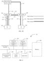
- the protocol stack applicable to the UE may be shown in FIG. 2 .
- a bottom layer is the internet protocol (internet protocol, IP).
- IP internet protocol
- UDP user datagram protocol
- SCTP datagram transport layer security
- SCTP conversational multimedia application
- RTP or RTCP media channel
- payload formats On the top of the RTP are payload formats (payload formats), and on the top of the payload formats is a speech (speech), video (video), or text (text). On the top of the speech, video, or text is a conversational multimedia application. On the top of the RTCP is also the conversational multimedia application.
- Session initiation protocol session initiation protocol, SIP
- the SIP session in embodiments of this application may represent an end-to-end SIP relationship that lasts for a period of time between two UEs in a call service.
- the SIP session helps to sort messages between two UEs in a call service, and enables requests between the two UEs to be correctly routed.
- a SIP session may be understood as a context for interpreting a SIP message.
- a SIP session can be constructed by using a request and a response. After the SIP session is set up, a request and a response can be sent in the SIP session.
- a SIP session may be constructed between two UEs by using an invite request (INVITE) message and a 183 message. After the SIP session is set up, the UEs may further send a reinvite request (reINVITE) message and a 200 message in the SIP session.
- ISVITE invite request
- reINVITE reinvite request
- the communication system may be a long term evolution (long term evolution, LTE) system, a 5th generation (5th generation, 5G) communication system, a wireless fidelity (wireless fidelity, Wi-Fi) system, a 3rd generation partnership project (3rd generation partnership project, 3GPP) related communication system, a future evolved communication system, or a system integrating a plurality of systems.
- LTE long term evolution
- 5th generation, 5G 5th generation
- 5G wireless fidelity
- Wi-Fi wireless fidelity
- 3rd generation partnership project 3rd generation partnership project, 3GPP
- 5G may also be referred to as new radio (new radio, NR).
- the following uses a communication system 30 shown in FIG. 3A and a communication system 31 shown in FIG. 3B as examples to describe the method provided in embodiments of this application.
- FIG. 3A is a schematic diagram of an architecture of the communication system 30 according to an embodiment of this application.
- the communication system 30 may include a data channel service entity 301 (corresponding to the "data channel service entity” in chapter “SUMMARY”), user equipment UE 302 (corresponding to the "first user equipment” in chapter “SUMMARY", or corresponding to the user equipment in chapter “SUMMARY”), and user equipment UE 303 (corresponding to the "second user equipment” in chapter “SUMMARY", or corresponding to the peer user equipment in chapter “SUMMARY”).
- the user equipment UE 302 and the user equipment UE 303 can communicate with the data channel service entity 301.
- FIG. 3A is merely a schematic diagram, and does not constitute a limitation on an applicable scenario of the technical solutions provided in this application.
- the data channel service entity 301 may be configured to transmit real-time interaction information between the UE 302 and the UE 303 that are in a same call service. Specifically, the data channel service entity 301 may establish a first data channel with the UE 302 and establish a first video channel with the UE 303. The first video channel is used to transmit data according to UDP. To be specific, the first video channel is a logical channel or a data connection for transmitting data according to UDP.
- the data channel service entity 301 may send, to the UE 303 through the first video channel, first real-time interaction information sent by the UE 302 through the first data channel, and/or send, to the UE 302 through the first data channel, second real-time interaction information sent by the UE 303 through the first video channel.
- the data channel service entity 301 may further establish a second data channel with the UE 302 and establish a second video channel with the UE 303.
- the second video channel is used to transmit data according to UDP.
- the data channel service entity 301 may send, to the UE 303 through the second video channel, RTCP data sent by the UE 302 through the second data channel, and/or send, to the UE 302 through the second data channel, RTCP data sent by the UE 303 through the second video channel.
- real-time interaction can be implemented between a user of UE (for example, the UE 302) that establishes a data channel and a user of UE that fails to establish a data channel (for example, the UE 303, where the UE 303 may fail to establish a data channel because the UE 303 does not support establishment of the data channel, or although the UE 303 may support establishment of a data channel but fails to establish the data channel due to specific reason, for example, a limitation of network resources) in a call service, or real-time interaction can be implemented between a user of UE that supports establishment of a data channel and a user of UE that does not support establishment of a data channel in a call service. This process is described in the following methods shown in FIG. 7 and FIG. 10 .
- a function of the data channel service entity may be provided by one network element, or may be jointly provided by a plurality of network elements.
- the function of the data channel service entity may be deployed on one network element, or may be deployed on a plurality of network elements, to enable the plurality of network elements to jointly implement the function of the data channel service entity.
- the data channel service entity 301 is used as an example.
- the function of the data channel service entity 301 may be provided by an IMS application server (IMS application server, IMS AS).
- IMS AS IMS application server
- the function of the data channel service entity 301 may be jointly provided by an IMS AS, a data channel server control plane (data channel server-control plane, DCS-C), and a data channel server-media plane (data channel server-media plane, DCS-M).
- the data channel service entity in this embodiment of this application may be a data channel service subsystem (data channel service subsystem, DCSS) defined in a 3GPP standard specification. For details, refer to an embodiment corresponding to FIG. 10 .
- media for example, real-time interaction information and/or audio and video media content
- IMS access media gateway IMS AGW
- the media of the UEs may alternatively be anchored to the IMS AGW, that is, the IMS AGW is included in a communication path of two UEs that are in a same call service. It may be understood that each UE in the call service may have a corresponding IMS AGW. In this way, based on whether media of the UE is anchored to the IMS AGW corresponding to the UE, the communication system may be deployed in the following three manners:
- Deployment manner 1 Media of UE 1 is anchored to an IMS AGW corresponding to the UE 1, and media of UE 2 is anchored to an IMS AGW corresponding to the UE 2, as shown in FIG. 3B .
- Deployment manner 2 Media of UE 1 is anchored to an IMS AGW corresponding to the UE 1, but media of UE 2 is not anchored to an IMS AGW corresponding to the UE 2.
- Deployment manner 3 Media of UE 1 is not anchored to an IMS AGW corresponding to the UE 1, but media of UE 2 is anchored to an IMS AGW corresponding to the UE 2.
- the following describes a communication system in a media anchored scenario by using the deployment manner 1 as an example. It may be understood that a case in which media of UE is anchored to an IMS AGW in the following embodiments of this application is described by using the deployment manner 1 as an example.
- the case in which media of UE is anchored to an IMS AGW in the deployment manner 2 or the deployment manner 3 is similar to the case in which media of UE is anchored to an IMS AGW in the deployment manner 1. Therefore, for details, refer to the case in which media of UE is anchored to an IMS AGW in the deployment manner 1. The details are not described again.
- FIG. 3B is a schematic diagram of an architecture of the communication system 31 according to an embodiment of this application.
- the communication system 31 may include a data channel service entity 311 (corresponding to the data channel service entity in chapter "SUMMARY"), an IMS AGW 314 and an IMS AGW 315 that can communicate with the data channel service entity 311, UE 312 (corresponding to the first user equipment in chapter “SUMMARY", or corresponding to the user equipment in chapter “SUMMARY”) that can communicate with the IMS AGW 314, and UE 313 (corresponding to the second user equipment in chapter “SUMMARY", or corresponding to the peer user equipment in chapter “SUMMARY”) that can communicate with the IMS AGW 315.
- FIG. 3B is merely a schematic diagram, and does not constitute a limitation on an applicable scenario of the technical solutions provided in this application.
- an IMS AGW may be configured to forward a message or data between the data channel service entity and UE, or between UEs that are in a same call service.
- the IMS AGW 314 may be configured to forward a message or data between the data channel service entity 311 and the UE 312, or between the UE 312 and the UE 313.
- the IMS AGW 315 may be configured to forward a message or data between the data channel service entity 311 and the UE 313, or between the UE 312 and the UE 313.
- the data channel service entity 311 refer to the descriptions of the data channel service entity in FIG. 3A . Details are not described herein again.
- an audio channel is established when a speech call is made between UEs, and an audio channel and a video channel are established when a video call is made between UEs.
- an audio channel established when a speech call is made between UEs may be shown in FIG. 4A
- an audio channel and a video channel that are established when a video call is made between UEs may be shown in FIG. 4B .
- an audio channel established when a speech call is made between UEs may be shown in FIG. 4C
- an audio channel and a video channel that are established when a video call is made between UEs may be shown in FIG. 4D .
- UE 401 (corresponding to the first user equipment in chapter “SUMMARY”, or corresponding to the user equipment in chapter “SUMMARY”) may establish an audio channel 406 with UE 402 (corresponding to the second user equipment in chapter “SUMMARY", or corresponding to the peer user equipment in chapter “SUMMARY”).
- the audio channel 406 does not pass through an IMS AGW.
- a communication path in which the audio channel 406 is located does not include an IMS AGW.
- the UE 401 and the UE 402 may transmit audio information through the audio channel 406.
- the UE 401 may establish an audio channel 407 and a video channel 408 with the UE 402.
- the audio channel 407 and the video channel 408 do not pass through an IMS AGW.
- a communication path in which the audio channel 407 is located does not include an IMS AGW
- a communication path in which the video channel 408 is located does not include an IMS AGW either.
- the UE 401 and the UE 402 may transmit audio information through the audio channel 407, and transmit video information through the video channel 408.
- the UE 401 may establish an audio channel 409 with the UE 402.
- the audio channel 409 passes through an IMS AGW 403 corresponding to the UE 401 and an IMS AGW 404 corresponding to the UE 402.
- a communication path in which the audio channel 409 is located includes the IMS AGW 403 and the IMS AGW 404.
- the UE 401 and the UE 402 may transmit audio information through the audio channel 409.
- the UE 401 may establish an audio channel 410 and a video channel 411 with the UE 402.
- the audio channel 410 and the video channel 411 pass through the IMS AGW 403 corresponding to the UE 401 and the IMS AGW 404 corresponding to the UE 402.
- a communication path in which the audio channel 410 is located includes the IMS AGW 403 and the IMS AGW 404
- a communication path in which the video channel 411 is located includes the IMS AGW 403 and the IMS AGW 404.
- the UE 401 and the UE 402 may transmit audio information through the audio channel 410, and transmit video information through the video channel 411.
- Option 1 A data channel service entity 405 (corresponding to the data channel service entity in chapter "SUMMARY") establishes a data channel with the UE 401, and establishes a video channel with the UE 402.
- the data channel service entity 405 implements transmission of real-time interaction information between the two UEs through data format conversion.
- a data channel and a video channel that are established by the data channel service entity 405 may be shown in FIG. 5A .
- the data channel service entity 405 establishes a data channel 412 with the UE 401, and establishes a video channel 413 with the UE 402.
- the data channel 412 and the video channel 413 do not pass through an IMS AGW.
- a communication path in which the data channel 412 is located does not include an IMS AGW
- a communication path in which the video channel 413 is located does not include an IMS AGW either.
- the UE 401 and the data channel service entity 405 may transmit data according to SCTP through the data channel 412.
- the data channel service entity 405 and the UE 402 transmit data according to UDP through the video channel 413.
- the data channel 412 may include a first data channel in the following embodiments of this application.
- the data channel 412 may further include a second data channel, and/or a third data channel, and/or a fourth data channel, and/or a second signaling application data channel in the following embodiments of this application.
- the video channel 413 may include a first video channel in the following embodiments of this application.
- the video channel 413 may further include a second video channel in the following embodiments of this application. It may be understood that the data channel service entity 405 may also establish an audio channel (not shown in FIG.
- the audio information sent by the UE 401 is not transmitted through the audio channel 406 originally established in FIG. 4A , but is forwarded to the UE 402 through the data channel service entity 405.
- the audio information sent by the UE 402 is not transmitted through the audio channel 406 originally established in FIG. 4A , but is forwarded to the UE 401 through the data channel service entity 405.
- a data channel and a video channel that are established by the data channel service entity 405 may be shown in FIG. 5B .
- the data channel service entity 405 establishes a data channel 414 with the UE 401, and establishes a video channel 415 with the UE 402.
- the data channel 414 and the video channel 415 do not pass through an IMS AGW.
- a communication path in which the data channel 414 is located does not include an IMS AGW
- a communication path in which the video channel 415 is located does not include an IMS AGW either.
- the UE 401 and the data channel service entity 405 may transmit data according to SCTP through the data channel 414.
- the data channel service entity 405 and the UE 402 transmit data according to UDP through the video channel 415.
- the data channel 414 may include a first data channel in the following embodiments of this application.
- the data channel 414 may further include a second data channel, and/or a third data channel, and/or a fourth data channel, and/or a second signaling application data channel in the following embodiments of this application.
- the video channel 415 may include a first video channel in the following embodiments of this application.
- the video channel 415 may further include a second video channel in the following embodiments of this application. It may be understood that the video channel 408 originally established in FIG. 4B may or may not be removed.
- the UE 401 may still send video information (for example, video information shot by a camera of the UE 401) through the video channel 408, but the UE 402 does not receive the video information, or the UE 402 receives the video information but does not process the video information.
- the data channel service entity 405 may also establish an audio channel (not shown in FIG. 5B ) with the UE 401, and establish an audio channel (not shown in FIG. 5B ) with the UE 402.
- the audio information sent by the UE 401 is not transmitted through the audio channel 407 originally established in FIG. 4B , but is forwarded to the UE 402 through the data channel service entity 405.
- the audio information sent by the UE 402 is not transmitted through the audio channel 407 originally established in FIG. 4B , but is forwarded to the UE 401 through the data channel service entity 405.
- a data channel and a video channel that are established by the data channel service entity 405 may be shown in FIG. 5C .
- the data channel service entity 405 establishes a data channel 416 with the UE 401, and establishes a video channel 417 with the UE 402.
- the data channel 416 and the video channel 417 pass through an IMS AGW
- a communication path in which the data channel 416 is located includes the IMS AGW 403
- a communication path in which the video channel 417 is located includes the IMS AGW 404.
- the UE 401 and the data channel service entity 405 may transmit data according to SCTP through the data channel 416.
- the data channel service entity 405 and the UE 402 transmit data according to UDP through the video channel 417.
- the data channel 416 may include a first data channel in the following embodiments of this application.
- the data channel 416 may further include a second data channel, and/or a third data channel, and/or a fourth data channel, and/or a second signaling application data channel in the following embodiments of this application.
- the video channel 417 may include a first video channel in the following embodiments of this application.
- the video channel 417 may further include a second video channel in the following embodiments of this application. It may be understood that the data channel service entity 405 may also establish an audio channel (not shown in FIG.
- the audio information sent by the UE 401 may reach the data channel service entity 405 through the IMS-AGW 403, and then the data channel service entity 405 forwards the audio information to the UE 402 through the IMS-AGW 404.
- the audio information sent by the UE 402 may reach the data channel service entity 405 through the IMS-AGW 404, and then the data channel service entity 405 forwards the audio information to the UE 401 through the IMS-AGW 403.
- a data channel and a video channel that are established by the data channel service entity 405 may be shown in FIG. 5D .
- the data channel service entity 405 establishes a data channel 418 with the UE 401, and establishes a video channel 419 with the IMS AGW 404.
- the data channel 418 and the video channel 419 pass through an IMS AGW.
- a communication path in which the data channel 418 is located includes the IMS AGW 403
- a communication path in which the video channel 419 is located includes the IMS AGW 404.
- the UE 401 and the data channel service entity 405 may transmit data according to SCTP through the data channel 418.
- the data channel service entity 405 and the UE 402 transmit data according to UDP through the video channel 419.
- the data channel 418 may include a first data channel in the following embodiments of this application.
- the data channel 418 may further include a second data channel, and/or a third data channel, and/or a fourth data channel, and/or a second signaling application data channel in the following embodiments of this application.
- the video channel 419 may include a first video channel in the following embodiments of this application.
- the video channel 419 may further include a second video channel in the following embodiments of this application. It may be understood that the data channel service entity 405 may also establish an audio channel (not shown in FIG.
- the audio information sent by the UE 401 may reach the data channel service entity 405 through the IMS-AGW 403, and then the data channel service entity 405 forwards the audio information to the UE 402 through the IMS-AGW 404.
- the audio information sent by the UE 402 may reach the data channel service entity 405 through the IMS-AGW 404, and then the data channel service entity 405 forwards the audio information to the UE 401 through the IMS-AGW 403. It may be understood that the video channel 411 originally established in FIG. 4D may or may not be removed.
- the UE 401 may still send video information (for example, video information shot by a camera of the UE 401) through the video channel 411, but the IMS AGW 404 does not receive the video information, or the IMS AGW 404 receives the video information but does not process the video information.
- video information for example, video information shot by a camera of the UE 401
- the IMS AGW 404 does not receive the video information, or the IMS AGW 404 receives the video information but does not process the video information.
- Option 2 An end-to-end data channel is established between the two UEs, and real-time interaction information is directly transmitted without being forwarded by the data channel service entity 405.
- a data channel may be established between the UE 401 and the UE 402.
- the data channel may be used to transmit the real-time interaction information.
- an audio channel and a video channel refer to the corresponding descriptions in FIG. 5A , FIG. 5B , FIG. 5C , or FIG. 5D .
- the communication system 30 shown in FIG. 3A and the communication system 31 shown in FIG. 3B are merely used as examples, and are not intended to limit the technical solutions of this application.
- a person skilled in the art may understand that, in a specific implementation process, the communication system 30 or the communication system 31 may further include another device.
- a quantity of UEs, data channel service entities, or IMS AGWs may also be determined based on a specific requirement. This is not limited.
- each network element or device for example, the UE or the data channel service entity in FIG. 3A or FIG. 3B in embodiments of this application may also be referred to as a communication apparatus, and may be a general-purpose device or a dedicated device. This is not specifically limited in embodiments of this application.
- each network element or device for example, the UE or the data channel service entity in FIG. 3A or FIG. 3B in embodiments of this application may be implemented by one device, or may be jointly implemented by a plurality of devices, or may be implemented by one or more functional modules in one device.
- This is not specifically limited in embodiments of this application. It may be understood that the foregoing functions may be network elements in a hardware device, or may be software functions running on dedicated hardware, a combination of hardware and software, or virtualized functions instantiated on a platform (for example, a cloud platform).
- each device or network element may use a composition structure shown in FIG. 6 , or include components shown in FIG. 6.
- FIG. 6 is a schematic diagram of a hardware structure of a communication apparatus applicable to an embodiment of this application.
- the communication apparatus 60 includes at least one processor 601 and at least one communication interface 604, and is configured to implement the method provided in embodiments of this application.
- the communication apparatus 60 may further include a communication line 602 and a memory 603.
- the processor 601 may be a general-purpose central processing unit (central processing unit, CPU), a microprocessor, an application-specific integrated circuit (application-specific integrated circuit, ASIC), or one or more integrated circuits configured to control program execution of the solutions in this application.
- CPU central processing unit
- ASIC application-specific integrated circuit
- the communication line 602 may include a path, for example, a bus, for transmitting information between the foregoing components.
- the communication interface 604 is configured to communicate with another device or a communication network.
- the communication interface 604 may be any apparatus such as a transceiver, for example, may be an Ethernet interface, a radio access network (radio access network, RAN) interface, a wireless local area network (wireless local area network, WLAN) interface, a transceiver, a pin, a bus, or a transceiver circuit.
- a transceiver for example, may be an Ethernet interface, a radio access network (radio access network, RAN) interface, a wireless local area network (wireless local area network, WLAN) interface, a transceiver, a pin, a bus, or a transceiver circuit.
- the memory 603 may be a read-only memory (read-only memory, ROM) or another type of static storage device that can store static information and instructions, or a random access memory (random access memory, RAM) or another type of dynamic storage device that can store information and instructions, or may be an electrically erasable programmable read-only memory (electrically erasable programmable read-only memory, EEPROM), a compact disc read-only memory (compact disc read-only memory, CD-ROM) or other compact disc storage, an optical disc storage (including a compact optical disc, a laser disc, an optical disc, a digital versatile disc, a Blu-ray disc, and the like), a magnetic disk storage medium or another magnetic storage device, or any other medium that can be configured to carry or store expected program code in a form of an instruction structure or a data structure and that can be accessed by a computer.
- ROM read-only memory
- RAM random access memory
- EEPROM electrically erasable programmable read-only memory
- CD-ROM compact
- the memory 603 is not limited thereto.
- the memory may exist independently, and is coupled to the processor 601 through the communication line 602.
- the memory 603 may alternatively be integrated with the processor 601.
- the memory provided in this embodiment of this application may be usually non-volatile.
- the memory 603 is configured to store computer-executable instructions for executing solutions provided in embodiments of this application, and the processor 601 controls execution.
- the processor 601 is configured to execute the computer-executable instructions stored in the memory 603, to implement the method provided in embodiments of this application.
- the processor 601 may perform processing-related functions in the method provided in the following embodiments of this application, and the communication interface 604 is responsible for communicating with another device or a communication network. This is not specifically limited in this embodiment of this application.
- the computer-executable instructions in this embodiment of this application may also be referred to as application code. This is not specifically limited in this embodiment of this application.
- the coupling in this embodiment of this application may be an indirect coupling or a communication connection between apparatuses, units, or modules in an electrical form, a mechanical form, or another form, and is used for information exchange between the apparatuses, the units, or the modules.
- the processor 601 may include one or more CPUs, for example, a CPU 0 and a CPU 1 in FIG. 6 .
- the communication apparatus 60 may include a plurality of processors, for example, the processor 601 and a processor 607 in FIG. 6 .
- Each of the processors may be a single-core processor (single-CPU), or may be a multi-core processor (multi-CPU).
- the processor herein may be one or more devices, circuits, and/or processing cores configured to process data (for example, computer program instructions).
- the communication apparatus 60 may further include an output device 605 and/or an input device 606.
- the output device 605 is coupled to the processor 601, and may display information in a plurality of manners.
- the output device 605 may be a liquid crystal display (liquid crystal display, LCD), a light emitting diode (light emitting diode, LED) display device, a cathode ray tube (cathode ray tube, CRT) display device, a projector (projector), or the like.
- the input device 606 is coupled to the processor 601, and may receive an input of a user in a plurality of manners.
- the input device 606 may be a mouse, a keyboard, a touchscreen device, a sensing device, or the like.
- composition structure shown in FIG. 6 does not constitute a limitation on the communication apparatus.
- the communication apparatus may include more or fewer components than those shown in the figure, combine some components, or have different component arrangements.
- transmit may be understood as “send and/or receive” based on a specific context. “Transmit” can be a noun or a verb. When an execution body of an action is not emphasized, “transmit” is often used instead of "send and/or receive”.
- a phrase “transmit real-time interaction information” may be understood as “send real-time interaction information” from a perspective of sender UE, or may be understood as “receive real-time interaction information” from a perspective of receiver UE.
- names of messages between network elements, names of parameters in the messages, or the like in the following embodiments of this application are merely examples, and there may be other names during specific implementation. This is not specifically limited in embodiments of this application.
- A/B may indicate A or B.
- the term “and/or” may be used to indicate that there are three relationships between associated objects.
- a and/or B may indicate the following three cases: Only A exists, both A and B exist, and only B exists, where A and B may be singular or plural.
- an expression similar to "at least one of A, B, and C" or "at least one of A, B, or C" is usually used to indicate any one of the following: Only A exists; only B exists; only C exists; both A and B exist; both A and C exist; both B and C exist; and all A, B, and C exist.
- the foregoing uses three elements A, B, and C as an example to describe the optional items of the project. When there are more elements in an expression, the meaning of the expression may be obtained according to the foregoing rules.
- first and second may be used to distinguish between technical features with same or similar functions.
- the terms such as “first” and “second” do not limit a quantity and an execution sequence, and the terms such as “first” and “second” do not indicate a definite difference.
- the term such as “example” or “for example” is used to represent an example, an illustration, or a description. Any embodiment or design scheme described with “example” or “for example” cannot be explained as being more preferred or having more advantages than another embodiment or design scheme. Use of the term such as “example” or “for example” is intended to present a related concept in a specific manner for ease of understanding.
- an embodiment means that particular features, structures, or characteristics related to the embodiment are included in at least one embodiment of this application. Therefore, embodiments throughout this specification do not necessarily refer to a same embodiment. In addition, these particular features, structures, or characteristics may be combined in one or more embodiments in any proper manner. It may be understood that sequence numbers of processes do not mean execution sequences in embodiments of this application. The execution sequences of the processes can be determined based on functions and internal logic of the processes, and cannot be construed as any limitation on implementation processes of embodiments of this application.
- some optional features in embodiments of this application may be independently implemented without depending on another feature, for example, a solution on which the optional features are currently based, to resolve a corresponding technical problem and achieve corresponding effect.
- the optional features may be combined with another feature based on a requirement.
- the apparatus provided in this embodiment of this application may also implement these features or functions. Details are not described herein.
- the UE or the data channel service entity may perform some or all of steps in embodiments of this application.
- the steps are merely examples.
- another step or a variation of various steps may be further performed.
- the steps may be performed in a sequence different from a sequence presented in embodiments of this application, and possibly, not all the steps in embodiments of this application need to be performed.
- FIG. 7 shows a communication method according to an embodiment of this application.
- the communication method is implemented based on FIG. 3A, FIG. 3B , FIG. 5A , FIG. 5B, FIG. 5C , FIG. 5D , and the like.
- a data channel service entity in the method shown in FIG. 7 is the data channel service entity 301
- first UE in the method shown in FIG. 7 is the UE 302
- second UE in the method shown in FIG. 7 is the UE 303.
- a data channel service entity in the method shown in FIG. 7 is the data channel service entity 311, first UE in the method shown in FIG. 7 is the UE 312, and second UE in the method shown in FIG. 7 is the UE 313.
- a data channel service entity in the method shown in FIG. 7 is the data channel service entity 405
- first UE in the method shown in FIG. 7 is the UE 401
- second UE in the method shown in FIG. 7 is the UE 402.
- the communication method may include S701 and S702.
- the data channel service entity establishes a first media information application data channel (corresponding to the first data channel in chapter "SUMMARY") with the first UE, and establishes a first video channel with the second UE.
- the first UE establishes the first media information application data channel with the data channel service entity
- the second UE establishes the first video channel with the data channel service entity.
- the first UE is calling-party user equipment
- the second UE is called-party user equipment.
- the first UE is called-party user equipment
- the second UE is calling-party user equipment.
- the first media information application data channel is used to transmit, according to SCTP, RTP data including real-time interaction information
- the first video channel is used to transmit, according to UDP, RTP data including real-time interaction information
- the data channel (for example, the first media information application data channel, a second media information application data channel, a bootstrap data channel, a first signaling application data channel, and/or a second signaling application data channel) in this embodiment of this application may be a data channel that is between the data channel service entity and the first UE and that does not pass through an IMS-AGW, or may be a data channel established by the data channel service entity with the first UE through an IMS-AGW.
- Unified descriptions are provided herein, and details are not described below again.
- the data channel service entity 301 may directly establish the first media information application data channel with the UE 302.
- the data channel service entity 311 may establish the first media information application data channel with the UE 312 through the IMS-AGW 314.
- the real-time interaction information sent by the UE 312 is forwarded to the data channel service entity 311 through the IMS-AGW 314, and the real-time interaction information sent by the data channel service entity 311 is forwarded to the UE 312 through the IMS-AGW 314.
- the data channel service entity sends, to the second UE through the first video channel, first real-time interaction information sent by the first UE through the first media information application data channel, and/or sends, to the first UE through the first media information application data channel, second real-time interaction information sent by the second UE through the first video channel.
- the first real-time interaction information may include at least one of the following: content shot by a camera, information generated by a thumbs-up, desktop sharing content, a mark drawn by a user on a screen, a text message, picture information, geographical location information, or video content in a video file.
- the second real-time interaction information may include content shot by a camera.
- the second UE sends a shot vehicle image to the data channel service entity through the first video channel.
- the data channel service entity sends the image to the first UE through the first media information application data channel.
- the first UE may display a vehicle on a display of the first UE.
- a user of the first UE may further draw a mark on the image of the vehicle, so that the first UE sends mark data (namely, data generated by the first UE for the mark) to the data channel service entity through the first media information application data channel.
- the data channel service entity may send the mark data to the second UE through the first video channel.
- the second UE may display the corresponding mark on the vehicle displayed on a display.
- the mark drawn by the user of the first UE is a type of real-time interaction information.
- the data channel service entity may further send, to the second UE through the first video channel, audio and video exchange content sent by the first UE through the first media information application data channel, and/or send, to the first UE through the first media information application data channel, audio and video exchange content sent by the second UE through the first video channel.
- that the data channel service entity sends, to the second UE through the first video channel, first real-time interaction information sent by the first UE through the first media information application data channel includes: The data channel service entity receives first RTP data from the first UE through the first media information application data channel, and sends the first RTP data to the second UE through the first video channel.
- the first RTP data includes the first real-time interaction information.
- the first real-time interaction information is superimposed in a video frame, and then data of the video frame in which the first real-time interaction information is superimposed is transmitted through an RTP data packet.
- the second UE may present the first real-time interaction information based on the first RTP data. For example, if the first real-time interaction information includes a mark drawn by the user on a screen, the second user equipment presents the mark on a screen of the second user equipment.
- that the data channel service entity sends, to the first UE through the first media information application data channel, second real-time interaction information sent by the second UE through the first video channel includes: The data channel service entity receives second RTP data from the second UE through the first video channel, and sends the second RTP data to the first UE through the first media information application data channel, where the second RTP data includes the second real-time interaction information. That the second RTP data includes the second real-time interaction information has a similar meaning with that the first RTP data includes the first real-time interaction information. For details, refer to the descriptions of that the first RTP data includes the first real-time interaction information in this embodiment of this application.
- the first UE may present the second real-time interaction information based on the second RTP data. For example, if the second real-time interaction information includes content shot by a camera of the second UE, the first user equipment presents the content on a screen of the first user equipment.
- a data packet transmitted through the first media information application data channel may be referred to as a data channel data packet
- a data packet transmitted through the first video channel may be referred to as a video channel data packet.
- the data channel data packet includes RTP data
- the RTP data includes real-time interaction information.
- the video channel data packet includes RTP data
- the RTP data includes real-time interaction information.
- a datagram protocol used for the data channel data packet is different from a datagram protocol used for the video channel data packet.
- the data channel service entity may parse the data channel data packet to obtain RTP data, encapsulate the RTP data into a video channel data packet, and send the video channel data packet to the second UE.
- the data channel service entity may parse the video channel data packet to obtain RTP data, encapsulate the RTP data into a data channel data packet, and send the data channel data packet to the first UE.
- a data channel data packet and a video channel data packet may be shown in FIG. 9A .
- a data channel data packet and a video channel data packet may be shown in FIG. 9A .
- the data channel data packet includes an IP header (IP header), a UDP header (UDP header), a DTLS header (DTLS header), an SCTP header (SCTP header), and RTP data.
- the video channel data packet includes an IP header, a UDP header, and RTP data.
- the data channel service entity may separately remove the IP header, the UDP header, and the DTLS header, decrypt an obtained data packet, remove the SCTP header from a decrypted data packet to obtain the RTP data, add a UDP header and an IP header to the RTP data to obtain the video channel data packet, and then send the video channel data packet to the second UE through the first video channel.
- the foregoing DTLS header and decryption process are optional. If the foregoing DTLS header does not exist, the foregoing decryption process does not exist.
- the video channel data packet when the second UE sends RTP data to the first UE through the first video channel, the video channel data packet includes an IP header, a UDP header, and second RTP data.
- the data channel data packet includes an IP header, a UDP header, a DTLS header, an SCTP header, and RTP data.
- the data channel service entity may separately remove the IP header and the UDP header to obtain the RTP data, add an SCTP header to the RTP data, encrypt the data packet to which the SCTP header is added, add a DTLS header, a UDP header, and an IP header to an encrypted data packet to obtain the data channel data packet, and then send the data channel data packet to the first UE through the first media information application data channel.
- the foregoing DTLS header and encryption process are also optional. If the foregoing encryption process does not exist, the foregoing DTLS header does not exist.
- that the data channel service entity sends, to the second UE through the first video channel, first real-time interaction information sent by the first UE through the first media information application data channel includes: The data channel service entity receives the first real-time interaction information from the first UE through the first media information application data channel, and sends third RTP data to the second UE through the first video channel, where the third RTP data includes the first real-time interaction information.
- the first UE may send the first real-time interaction information to the data channel service entity.
- the data channel service entity After receiving the first real-time interaction information, the data channel service entity superimposes the first real-time interaction information into a video frame, and then sends, to the second UE through the third RTP data, data of the video frame in which the first real-time interaction information is superimposed.
- a size of the first real-time interaction information is smaller than that of the third RTP data. Therefore, traffic between the first UE and the data channel service entity can be saved.
- the second UE may present the first real-time interaction information based on the third RTP data. For example, if the first real-time interaction information includes a mark drawn by the user on a screen, the second user equipment presents the mark on a screen of the second user equipment.
- that the data channel service entity sends, to the first UE through the first media information application data channel, second real-time interaction information sent by the second UE through the first video channel includes: The data channel service entity receives fourth RTP data from the second UE through the first video channel, extracts the second real-time interaction information from the fourth RTP data, and sends the second real-time interaction information to the first UE through the first media information application data channel.
- the data channel service entity extracts the second real-time interaction information from the fourth RTP data may be understood as follows:
- the data channel service entity extracts the second real-time interaction information through image recognition.
- the fourth RTP data includes a video, and the video includes a nod action or an "OK" gesture of a user.
- the data channel service entity recognizes the nod or the "OK" gesture of the user by using an image recognition technology, and sends information indicating yes (yes) to the first UE.
- the information indicating yes is a type of real-time interaction information.
- the first UE may present the second real-time interaction information.
- the second real-time interaction information includes content shot by a camera of the second UE, and the content includes a nod action or an "OK" gesture of a user
- the first user equipment presents, on the screen of the first user equipment, information indicating yes, for example, a picture including the "OK" gesture.
- the first video channel has an association relationship with the first media information application data channel.
- an end point (end point) corresponding to the first video channel has an association relationship with an identifier of the first media information application data channel, or an IP address and a port number of the first video channel have an association relationship with an identifier of the first media information application data channel.
- the data channel service entity may determine that the real-time interaction information sent by the first UE through the first media information application data channel is to be sent to the second UE through the first video channel, and the real-time interaction information sent by the second UE through the first video channel is to be sent to the first UE through the first media information application data channel.
- that the first video channel has an association relationship with the first media information application data channel may be understood as that the data channel service entity establishes a correspondence between the first video channel and the first media information application data channel.
- the data channel service entity may establish the first media information application data channel with the first UE, and establish the first video channel with the second UE. In this way, the data channel service entity may send, to the second UE through the first video channel, the real-time interaction information sent by the first UE through the first media information application data channel, and/or send, to the first UE through the first media information application data channel, the real-time interaction information sent by the second UE through the first video channel.
- real-time interaction is implemented between a user of the first UE that supports establishment of a data channel and a user of the second UE that does not support establishment of a data channel in a call service, or real-time interaction is implemented between a user of the first UE that establishes a data channel and a user of the second UE that fails to establish a data channel in a call service.
- a data channel server may further establish a second media information application data channel (corresponding to the second data channel in chapter "SUMMARY") with the first UE, and establish a second video channel with the second UE.
- the data channel service entity may send, to the second UE through the second video channel, control data that is sent by the first UE through the second media information application data channel and that is used for controlling RTP data, and/or send, to the first UE through the second media information application data channel, control data that is sent by the second UE through the second video channel and that is used for controlling RTP data, to control the RTP data.
- the method shown in FIG. 7 further includes S701a and S703.
- the data channel service entity establishes a second media information application data channel with the first UE, and establishes a second video channel with the second UE.
- the first UE establishes the second media information application data channel with the data channel service entity
- the second UE establishes the second video channel with the data channel service entity.
- the second media information application data channel is used to transmit RTCP data according to SCTP.
- the RTCP data includes control data and may be used to control RTP data.
- the second video channel is used to transmit RTCP data according to UDP.
- the data channel service entity sends, to the second UE through the second video channel, RTCP data sent by the first UE through the second media information application data channel, and/or sends, to the first UE through the second media information application data channel, RTCP data sent by the second UE through the second video channel.
- the RTCP data may include control data for controlling RTP data.
- a data packet transmitted through the second media information application data channel may be referred to as a data channel data packet
- a data packet transmitted through the second video channel may be referred to as a video channel data packet.
- the data channel data packet includes RTCP data.
- the video channel data packet includes RTCP data.
- a datagram protocol used for the data channel data packet is different from a datagram protocol used for the video channel data packet.
- the data channel service entity may parse the data channel data packet to obtain RTCP data, encapsulate the RTCP data into a video channel data packet, and send the video channel data packet to the second UE.
- the data channel service entity may parse the video channel data packet to obtain RTCP data, encapsulate the RTCP data into a data channel data packet, and send the data channel data packet to the first UE.
- a data channel data packet and a video channel data packet may be shown in FIG. 9B .
- the data channel data packet includes an IP header, a UDP header, a DTLS header, an SCTP header, and RTCP data.
- the video channel data packet includes an IP header, a UDP header, and RTCP data.
- the data channel service entity may separately remove the IP header, the UDP header, and the DTLS header, decrypt an obtained data packet, remove the SCTP header from a decrypted data packet to obtain the RTCP data, add a UDP header and an IP header to the RTCP data to obtain the video channel data packet, and then send the video channel data packet to the second UE through the second video channel.
- the foregoing DTLS header and decryption process are optional. If the foregoing DTLS header does not exist, the foregoing decryption process does not exist.
- the video channel data packet when the second UE sends RTCP data to the first UE through the second video channel, the video channel data packet includes an IP header, a UDP header, and RTCP data.
- the data channel data packet includes an IP header, a UDP header, a DTLS header, an SCTP header, and RTCP data.
- the data channel service entity may separately remove the IP header and the UDP header to obtain the RTCP data, add an SCTP header to the RTCP data, encrypt the data packet to which the SCTP header is added, add a DTLS header, a UDP header, and an IP header to an encrypted data packet to obtain the data channel data packet, and then send the data channel data packet to the first UE through the second media information application data channel.
- the foregoing DTLS header and encryption process are also optional. If the foregoing encryption process does not exist, the foregoing DTLS header does not exist.
- the second video channel has an association relationship with the second media information application data channel.
- an end point (end point) corresponding to the second video channel has an association relationship with an identifier of the second media information application data channel, or an IP address and a port number of the second video channel have an association relationship with an identifier of the second media information application data channel.
- the data channel service entity may determine that the RTCP data sent by the first UE through the second media information application data channel is to be sent to the second UE through the second video channel, and the RTCP data sent by the second UE through the second video channel is to be sent to the first UE through the second media information application data channel.
- that the second video channel has an association relationship with the second media information application data channel may be understood as that the data channel service entity establishes a correspondence between the second video channel and the second media information application data channel.
- a data channel used to transmit RTP data (for example, the first media information application data channel) and a data channel used to transmit RTCP data (for example, the second media information application data channel) are separately established between the data channel service entity and UE.
- the RTP data and the RTCP data may alternatively share one data channel.
- the data channel service entity may establish a data channel A with the first UE, and establish video channels A and B with the second UE.
- the data channel A is used to transmit RTP data including real-time interaction information according to SCTP, and transmit RTCP data according to SCTP.
- the video channel A is used to transmit RTP data including real-time interaction information according to UDP
- the video channel B is used to transmit RTCP data according to UDP.
- RTP data sent by the first UE may be sent to the data channel service entity through the data channel A.
- the data channel service entity After receiving the RTP data, the data channel service entity sends the RTP data to the second UE through the video channel A.
- RTCP data sent by the first UE may be sent to the data channel service entity through the data channel A.
- the data channel service entity After receiving the RTCP data, the data channel service entity sends the RTCP data to the second UE through the video channel B.
- RTP data sent by the second UE may be sent to the data channel service entity through the video channel A.
- the data channel service entity After receiving the RTP data, the data channel service entity sends the RTP data to the first UE through the data channel A.
- RTCP data sent by the second UE may be sent to the data channel service entity through the video channel B.
- the data channel service entity After receiving the RTCP data, the data channel service entity sends the RTCP data to the second UE through the data channel A.
- S701a may be replaced with the following step:
- the data channel service entity establishes a second video channel with the second UE.
- the second UE establishes the second video channel with the data channel service entity.
- S703 may be replaced with the following step: The data channel service entity sends, to the second UE through the second video channel, RTCP data sent by the first UE through the first media information application data channel, and/or sends, to the first UE through the first media information application data channel, RTCP data sent by the second UE through the second video channel.
- the data channel service entity may determine not to establish a data channel between the data channel service entity and the second UE.
- the data channel service entity establishes a video channel, for example, the first video channel or the second video channel, with the second UE.
- the method shown in FIG. 7 further includes S700a.
- the data channel service entity determines not to establish a data channel between the data channel service entity and the second UE.
- the data channel service entity may determine, in at least the following two manners (S700a-1 or S700a-2), not to establish a data channel between the data channel service entity and the second UE.
- the data channel service entity receives, from the second UE, indication information indicating whether a data channel is successfully established (corresponding to the first indication information in chapter "SUMMARY").
- the indication information indicating whether a data channel is successfully established indicates a failure to establish a data channel between the data channel service entity and the second UE.
- the data channel service entity After receiving, from the second UE, the indication information indicating whether a data channel is successfully established, the data channel service entity determines, based on the indication information indicating whether a data channel is successfully established, not to establish a data channel between the data channel service entity and the second UE.
- the data channel service entity sends, to the second UE, information for requesting to establish a data channel with the second UE (corresponding to the first request information in chapter "SUMMARY").
- the information for requesting to establish a data channel with the second UE carries media description information used by the data channel service entity to establish a data channel with the second UE.
- the information for requesting to establish a data channel with the second UE may be an invite request message (for example, an INVITE message 2 in a method shown in FIG. 10 below).
- the second UE After receiving the information for requesting to establish a data channel with the second UE, the second UE sends first response information to the data channel service entity.
- the first response information includes indication information indicating whether a data channel is successfully established.
- the data channel service entity may determine, based on the indication information indicating whether a data channel is successfully established, not to establish a data channel between the data channel service entity and the second UE.
- the first response information may be included in a 183 message (for example, a 183 message 1 in the method shown in FIG. 10 ).
- Any response information (for example, the first response information, second response information, third response information, or fourth response information) in this embodiment of this application may be included in one response message for transmission. Unified descriptions are provided herein, and details are not described below again.
- the first UE is calling-party user equipment
- the second UE is called-party user equipment.
- the data channel service entity initiates, to the second UE, the request for establishing a data channel with the second UE, receives the first response information, and determines that the data channel fails to be established between the data channel service entity and the second UE, the data channel service entity may determine not to establish a data channel between the data channel service entity and the second UE.
- the data channel service entity may determine to establish a data channel between the data channel service entity and the second UE.
- the data channel service entity receives, from the second UE, information for requesting to establish a channel other than a data channel (corresponding to the second request information in chapter "SUMMARY"), and determines, based on a case in which the information for requesting to establish a channel other than a data channel does not carry the media description information used by the second UE to establish a data channel with the data channel service entity, not to establish a data channel between the second UE and the data channel service entity.
- the information for requesting to establish a channel other than a data channel may be an invite request message (for example, an INVITE message 3 in the method shown in FIG. 10 below).
- the first UE is called-party user equipment
- the second UE is calling-party user equipment.
- the data channel service entity may determine not to establish a data channel between the data channel service entity and the second UE.
- the data channel service entity may determine to establish a data channel between the data channel service entity and the second UE.
- the data channel service entity may indicate, to the first UE, whether to establish a data channel between the second UE and the data channel service entity (for example, indicate through S700c), so that the first UE determines whether to establish, between the first UE and the second UE, a data channel used to transmit real-time interaction information, or to establish, between the first UE and the data channel service entity, a data channel used to transmit real-time interaction information.
- the first UE may further request the data channel service entity to establish a data channel (for example, the first media information application data channel) used to transmit real-time interaction information with the first UE, and establish a video channel (for example, the first video channel) with the second UE. Subsequently, the data channel service entity may transmit real-time interaction information between the first UE and the second UE through data packet format conversion.
- a data channel for example, the first media information application data channel
- a video channel for example, the first video channel
- the method shown in FIG. 7 further includes S700c.
- the data channel service entity sends data channel capability indication information (corresponding to the third indication information in chapter "SUMMARY") to the first UE.
- the first UE receives the data channel capability indication information from the data channel service entity.
- the data channel capability indication information indicates whether to establish a data channel between the second UE and the data channel service entity. It may be understood that the data channel capability indication information may alternatively be included in a response message and sent to the first UE.
- the data channel capability indication information indicates not to establish a data channel between the second UE and the data channel service entity.
- the first UE may establish a data channel (for example, the first media information application data channel, or the first media information application data channel and/or the second media information application data channel) between the first UE and the data channel service entity, and establish a video channel (for example, the first video channel, or the first video channel and/or the second video channel) between the data channel service entity and the second UE.
- the data channel capability indication information indicates to establish a data channel between the second UE and the data channel service entity.
- the first UE may establish a data channel between the first UE and the second UE.
- the data channel service entity sends the data channel capability indication information to the first UE based on a request of the first UE.
- the method shown in FIG. 7 further includes S700b.
- the first UE sends data channel capability query request information (corresponding to the third request information in chapter "SUMMARY") to the data channel service entity.
- the data channel service entity receives the data channel capability query request information from the first UE.
- peer UE is any one or more UEs except the first UE in a plurality of UEs involved in one call service.
- the plurality of UEs involved in the call service are UE 1 and UE 2. If the first UE is the UE 1, the peer UE is the UE 2.
- the data channel capability query request information may be used to request information about whether to establish a data channel between the second UE and the data channel service entity.
- the first UE may send the data channel capability query request information to the data channel service entity.
- the first UE establishes a bootstrap data channel (corresponding to the third data channel in chapter "SUMMARY") with the data channel service entity.
- the data channel service entity establishes the bootstrap data channel with the first UE.
- the first UE sends the data channel capability query request information to the data channel service entity through the bootstrap data channel.
- the data channel capability query request information is used to request whether the peer UE (namely, the second UE) can establish a data channel or whether the peer UE has established a data channel.
- the data channel service entity sends the data channel capability indication information to the first UE through the bootstrap data channel.
- the data channel capability indication information indicates whether the second UE can establish a data channel or whether the second UE has established a data channel.
- the data channel service entity receives the data channel capability query request information from the first UE through the bootstrap data channel, and the first UE receives the data channel capability indication information from the data channel service entity through the bootstrap data channel.
- Data transmitted through the bootstrap data channel may be different from data transmitted through the first media information application data channel or the second media information application data channel.
- the data channel capability query request information and the data channel capability indication information may or may not be transmitted through the bootstrap data channel. This is not limited.
- S700b may be performed before S700a, or may be performed after S700a. This is not limited.
- the first UE may negotiate with the data channel service entity about media description information, where the media description information carries a parameter of RTP data transmitted in the first media information application data channel, for example, an encoding/decoding parameter of the RTP data, and the data channel service entity may negotiate with the second UE about media description information used to establish the first video channel between the data channel service entity and the second UE.
- the first UE sends video channel establishment trigger information (corresponding to the fourth request information in chapter "SUMMARY") to the data channel service entity.
- the video channel establishment trigger information is used to trigger the data channel service entity to establish the first video channel with the second UE.
- the data channel service entity receives the video channel establishment trigger information from the first UE.
- the video channel establishment trigger information may carry first media description information and indication information for establishing the first video channel (corresponding to the second indication information in chapter "SUMMARY").
- the first media description information carries a parameter of RTP data transmitted by the first UE through the first media information application data channel, for example, an encoding/decoding parameter of the RTP data.
- the indication information for establishing the first video channel is used to request to establish the first video channel.
- the video channel establishment trigger information further carries an identifier of the first media information application data channel, to indicate, to the data channel service entity, a data channel used to transmit RTP data.
- the video channel establishment trigger information further carries an identifier of the second media information application data channel, to indicate, to the data channel service entity, a data channel used to transmit RTCP data.
- the data channel service entity may send video channel establishment request information to the second UE based on the indication information for establishing the first video channel, to establish the first video channel.
- the video channel establishment request information may include the parameter that is of the RTP data and that is carried in the first media description information.
- the identifier of the first media information application data channel may be configured by a device that initiates establishment of the first media information application data channel.
- the identifier of the first media information application data channel is configured by the first UE; or if the data channel service entity is the device that initiates establishment of the first media information application data channel, the identifier of the first media information application data channel is configured by the data channel service entity.
- the identifier of the second media information application data channel may be configured by a device that initiates establishment of the second media information application data channel.
- the identifier of the first media information application data channel is an integer.
- the identifier of the first media information application data channel plus 1 is the identifier of the second media information application data channel.
- a port number corresponding to a video channel used to transmit, according to UDP, RTP data including real-time interaction information has an association relationship with or has no association relationship with a port number corresponding to a video channel used to transmit, according to UDP, RTCP data including control data.
- the port number corresponding to the video channel used to transmit, according to UDP, the RTP data including the real-time interaction information plus 1 is the port number corresponding to the video channel used to transmit, according to UDP, the RTCP data including the control data.
- a port number corresponding to the first video channel plus 1 is a port number corresponding to the second video channel.
- the first UE if the first UE establishes the bootstrap data channel with the data channel service entity, the first UE sends the video channel establishment trigger information to the data channel service entity through the bootstrap data channel.
- the data channel service entity receives the video channel establishment trigger information from the first UE through the bootstrap data channel.
- the first UE may further establish another data channel with the data channel service entity, to transmit the video channel establishment trigger information and a video channel establishment result (corresponding to the third response information in chapter "SUMMARY").
- the first UE establishes a first signaling application data channel (corresponding to the fourth data channel in chapter "SUMMARY") with the data channel service entity.
- the data channel service entity establishes the first signaling application data channel with the first UE.
- the video channel establishment trigger information and the video channel establishment result may alternatively not be transmitted through a data channel. This is not limited.
- the data channel service entity sends video channel establishment request information (corresponding to the fifth request information in chapter "SUMMARY") to the second UE.
- the video channel establishment request information is used to request to establish the first video channel with the second UE.
- the second UE receives the video channel establishment request information from the data channel service entity.
- the video channel establishment request information carries second media description information.
- the second media description information is media description information used by the data channel service entity to establish the first video channel.
- the fifth request message may be a reINVITE message.
- the second UE sends a video channel establishment response (corresponding to the second response information in chapter "SUMMARY") to the data channel service entity.
- the data channel service entity receives the video channel establishment response from the second UE.
- the video channel establishment response carries third media description information.
- the third media description information is media description information used by the second UE to establish the first video channel.
- the data channel service entity sends the video channel establishment result to the first UE.
- the first UE receives the video channel establishment result from the data channel service entity.
- the video channel establishment result carries fourth media description information.
- the fourth media description information carries a parameter of RTP data transmitted by the data channel service entity through the first media information application data channel, for example, an encoding/decoding parameter of the RTP data.
- the video channel establishment result further carries the identifier of the first media information application data channel, to indicate, to the first UE, a data channel used to transmit RTP data.
- the video channel establishment result further carries the identifier of the second media information application data channel, to indicate, to the first UE, a data channel used to transmit RTCP data.
- the data channel service entity sends the video channel establishment result to the first UE through the bootstrap data channel.
- the first UE receives the video channel establishment result from the data channel service entity through the bootstrap data channel.
- the data channel service entity sends the video channel establishment result to the first UE through the first signaling application data channel.
- the first UE receives the video channel establishment result from the data channel service entity through the first signaling application data channel.
- the first UE triggers, based on the indication information for establishing the first video channel in the video channel establishment trigger information, establishment of the first video channel between the data channel service entity and the second UE.
- the data channel service entity may alternatively trigger establishment of the first video channel between the data channel service entity and the second UE. This is not limited.
- the data channel (for example, the first media information application data channel, and/or the second media information application data channel, and/or the bootstrap data channel, and/or the first signaling application data channel) in this embodiment of this application may be established through a same SIP session, or may be established through different SIP sessions.
- Establishing a data channel through a SIP session may be understood as establishing the data channel in a process of establishing the SIP session, for example, establishing the data channel by carrying media description information for establishing the data channel through a request and/or a response for constructing the SIP session (for example, if the first media information application data channel is to be established, media description information for establishing the first media information application data channel is carried).
- establishing a data channel through a SIP session may be understood as establishing the data channel by carrying media description information for establishing the data channel in a request and/or response sent in the SIP session after the SIP session is set up.
- the data channel in this embodiment of this application may be established through a first SIP session.
- the first SIP session is a SIP session for establishing a call.
- the first SIP session is another SIP session independent of a SIP session for establishing a call. That is, the first SIP session may or may not be a SIP session for establishing a call.
- media of an IMS data channel is carried on an IMS access point name (access point name, APN).
- APN access point name
- media of an IMS data channel is carried on a data access point name (data access point name, data APN).
- the first media information application data channel, the second media information application data channel, the bootstrap data channel, and the first signaling application data channel may be established through at least two SIP sessions.
- the first media information application data channel and the second media information application data channel are established through a SIP session 1, and the bootstrap data channel and the first signaling application data channel are established through a SIP session 2.
- the SIP session 1 is a SIP session for establishing a call
- the SIP session 2 is not a SIP session for establishing a call.
- the first media information application data channel is established through a SIP session 1
- the second media information application data channel is established through a SIP session 2
- the bootstrap data channel and the first signaling application data channel are established through a SIP session 3.
- the SIP session 1 is a SIP session for establishing a call
- the SIP session 2 and the SIP session 3 are not SIP sessions for establishing a call.
- the SIP session 2 and the SIP session 3 are different sessions.
- actions of the data channel service entity, the first UE, or the second UE in the method shown in FIG. 7 may be performed by the processor 601 in the communication apparatus 60 shown in FIG. 6 by invoking the application program code stored in the memory 603. This is not limited in this embodiment of this application.
- FIG. 10 shows another communication method according to an embodiment of this application.
- the communication method includes S1001 to S1015.
- a DCMTSI client (corresponding to the first user equipment in chapter “SUMMARY"), a DCSS (corresponding to the data channel service entity in chapter “SUMMARY”), and an MTSI client (corresponding to the second user equipment in chapter “SUMMARY”) negotiate with each other about media description information for establishing a bootstrap data channel.
- a process of S1001 when the DCMTSI client is calling-party user equipment and the MTSI client is called-party user equipment is different from that when the DCMTSI client is called-party user equipment and the MTSI client is calling-party user equipment.
- the process of S1001 when the bootstrap data channel is established through a SIP session for establishing a call is also different from that when the bootstrap data channel is not established through the SIP session for establishing the call. Specifically, there may be the following four cases:
- Case 1 When the DCMTSI client is the calling-party user equipment, the MTSI client is the called-party user equipment, and the bootstrap data channel is established through the SIP session for establishing the call, for a specific process of S1001, refer to corresponding descriptions in the following case 1.
- Case 2 When the DCMTSI client is the called-party user equipment, the MTSI client is the calling-party user equipment, and the bootstrap data channel is established through the SIP session for establishing the call, for a specific process of S1001, refer to corresponding descriptions in the following case 2.
- Case 3 When the DCMTSI client is the calling-party user equipment, the MTSI client is the called-party user equipment, and the bootstrap data channel is not established through the SIP session for establishing the call, for a specific process of S1001, refer to corresponding descriptions in the following case 3.
- Case 4 When the DCMTSI client is the called-party user equipment, the MTSI client is the calling-party user equipment, and the bootstrap data channel is not established through the SIP session for establishing the call, for a specific process of S1001, refer to corresponding descriptions in the following case 4.
- the process of S1001 may include S1.1 to S1.4.
- the DCMTSI client initiates a call, and sends an invite request (INVITE) message 1, where the INVITE message 1 is routed to the DCSS through a first proxy call session control function (proxy call session control function, P-CSCF) and a first serving call session control function (serving call session control function, S-CSCF).
- proxy call session control function proxy call session control function
- serving call session control function serving call session control function
- the INVITE message 1 may carry media description information 1 used by the DCMTSI client to establish a bootstrap data channel with the DCSS.
- the media description information 1 may include related parameters needed for establishing a data channel, such as a port number, a bandwidth, a size of one piece of information, and the like.
- the media description information 1 may be shown as follows:
- the port number is 10001
- the bandwidth is 500 Kbps (Kbps)
- the size of one piece of information is 1024 bytes (bytes)
- a port number of SCTP is 5000.
- the DCSS replaces the media description information 1 in the INVITE message 1 with media description information 2 used by the DCSS to establish a bootstrap data channel with the MTSI client, to obtain an INVITE message 2, and sends the INVITE message 2, where the INVITE message 2 is routed to the MTSI client through the first S-CSCF, a second S-CSCF, and a second P-CSCF.
- the media description information 2 may include related parameters needed for establishing a data channel, such as a port number and the like.
- the MTSI client sends a 183 message 1, where the 183 message 1 is routed to the DCSS through the second P-CSCF, the second S-CSCF, and the first S-CSCF.
- the 183 message 1 carries session description protocol (session description protocol, SDP) answer media description information in the INVITE message 2. If the MTSI client does not establish a data channel with the DCSS, the media description information indicates a failure to establish a data channel between the DCSS and the MTSI client. For example, a media (m) line port in the media description information is set to 0, to indicate that the MTSI client does not establish a data channel or fails to establish a data channel with the DCSS. The DCSS may determine, based on the 183 message 1, that no data channel is established between the MTSI client and the DCSS.
- SDP session description protocol
- the operation of setting the m line port to 0 may be performed by the MTSI client, or may be performed by an application server (application server, AS) in a network in which the MTSI client is located. This is not limited.
- the MTSI client establishes a data channel with the DCSS
- the media description information includes a media description used by the MTSI client to establish a bootstrap data channel with the DCSS.
- the DCSS may determine, based on the 183 message 1, that a data channel is to be established between the MTSI client and the DCSS.
- the method shown in FIG. 10 is described by using an example in which the MTSI client does not establish a data channel with the DCSS. That is, steps after S1.3 are described on a premise that the MTSI client does not establish a data channel with the DCSS.
- the DCSS replaces the media description information that is related to the bootstrap data channel and that is in the 183 message 1 with media description information 3 used by the DCSS to establish a bootstrap data channel with the DCMTSI client, to obtain a 183 message 2, and sends the 183 message 2, where the 183 message 2 is routed to the DCMTSI client through the first S-CSCF and the first P-CSCF.
- S1.1 to S1.4 are also a process of setting up a call SIP session, that is, for the case 1, in the process of setting up the call SIP session, the DCMTSI client, the DCSS, and the MTSI client negotiate with each other about media description information for establishing a bootstrap data channel.
- the process of S1001 may include S2.1 to S2.4.
- the MTSI client initiates a call and sends an INVITE message 3, where the INVITE message 3 is routed to the DCSS through the second P-CSCF, the second S-CSCF, and the first S-CSCF.
- the INVITE message 3 does not carry media description information used by the MTSI client to establish a bootstrap data channel with the DCSS.
- the DCSS may determine, based on a case in which the INVITE message 3 does not carry the media description information used by the MTSI client to establish a bootstrap data channel with the DCSS, that no data channel is established between the MTSI client and the DCSS.
- the DCSS determines that the INVITE message 3 does not carry the media description information used by the MTSI client to establish a bootstrap data channel with the DCSS, adds media description information 4 used by the DCSS to establish a bootstrap data channel with the DCMTSI client to the INVITE message 3, to obtain an INVITE message 4, and sends the INVITE message 4, where the INVITE message 4 is routed to the DCMTSI client through the first S-CSCF and the first P-CSCF.
- the media description information 4 may include related parameters needed for establishing a data channel, such as a port number and the like.
- the DCMTSI client sends a 183 message 3, where the 183 message 3 is routed to the DCSS through the first P-CSCF and the first S-CSCF.
- the 183 message 3 carries, through an SDP answer, media description information 5 used by the DCMTSI client to establish a bootstrap data channel with the DCSS.
- the DCSS deletes the media description information 5 in the 183 message 3, to obtain a 183 message 4, and sends the 183 message 4, where the 183 message 4 is routed to the MTSI client through the first S-CSCF, the second S-CSCF, and the second P-CSCF.
- S2.1 to S2.4 are also a process of setting up a call SIP session, that is, for the case 2, in the process of setting up the call SIP session, the DCMTSI client, the DCSS, and the MTSI client negotiate with each other about media description information for establishing a bootstrap data channel.
- the process of S1001 may include S3.1 to S3.4.
- the DCMTSI client Before S1001, the DCMTSI client initiates a call, and constructs a SIP session 1 by using an INVITE message and a 183 message.
- the SIP session 1 is a SIP session for establishing a call.
- the DCMTSI client sends an INVITE message 5, where the INVITE message 5 is routed to the DCSS through the first P-CSCF and the first S-CSCF.
- the INVITE message 5 may carry media description information 6 used by the DCMTSI client to establish a bootstrap data channel with the DCSS.
- the media description information 6 may include related parameters needed for establishing a data channel, such as a port number and the like.
- the INVITE message 5 is initiated through another SIP session 2 different from the SIP session 1.
- the DCSS replaces the media description information 6 in the INVITE message 5 with media description information 7 used by the DCSS to establish a bootstrap data channel with the MTSI client, to obtain an INVITE message 6, and sends the INVITE message 6.
- the media description information 6 may include related parameters needed for establishing a data channel, such as a port number and the like.
- the DCSS determines not to establish a data channel between the MTSI client and the DCSS.
- the MTSI client does not support establishment of a data channel.
- the second S-CSCF does not find UE that supports establishment of a data channel, and the second S-CSCF sends a 4XX message, a 5XX message, or a 6XX message to the DCSS.
- the DCSS determines, based on the 4XX message, the 5XX message, or the 6XX message, that no data channel is established between the MTSI client and the DCSS.
- a SIP session used to negotiate an IMS data channel is carried on a data APN. Therefore, UE that supports a data channel needs to initiate a SIP registration to a network by using the data APN, and is authenticated by the network. Then, the UE can establish the data channel. The registration is independent of an original SIP registration of the UE. The original SIP registration of the UE is carried on an IMS APN.
- the second S-CSCF determines, based on the received 4XX message or 5XX message or 6XX message, that no data channel is established between the MTSI client and the DCSS.
- I-CSCF interrogating call session control function
- the DCSS determines, based on the 4XX message, the 5XX message, or the 6XX message, that no data channel is established between the MTSI client and the DCSS.
- the DCSS sends a 200 message, where the 200 message is routed to the DCMTSI client through the first S-CSCF and the first P-CSCF.
- the 200 message carries media description information used by the DCSS to establish a bootstrap data channel with the DCMTSI client.
- the DCMTSI client, the DCSS, and the MTSI client negotiate, through the another SIP session, media description information for establishing a bootstrap data channel.
- the MTSI client before S1001, the MTSI client initiates a call, and constructs a SIP session 1 by using an INVITE message and a 183 message.
- the SIP session 1 is a SIP session for establishing a call.
- a process in which the DCMTSI client, the DCSS, and the MTSI client negotiate with each other about media description information for a bootstrap data channel is similar to that in the case 3. Therefore, for details, refer to the descriptions in the case 3. The details are not described again.
- the MTSI client before S1001, the MTSI client initiates a call, and constructs a SIP session 1 by using an INVITE message and a 183 message.
- the SIP session 1 is a SIP session for establishing a call.
- the DCSS does not receive media description information for negotiating with the DCSS about a bootstrap data channel from the MTSI client within a period of time.
- the DCSS may initiate an INVITE message for establishing a SIP session 2 to the DCMTSI client.
- the message carries media description information for establishing a bootstrap data channel between the DCSS and the DCMTSI client, to trigger establishment of the bootstrap data channel between the DCSS and the DCMTSI client.
- the DCMTSI client may return a 200 message, to establish the bootstrap data channel between the DCMTSI client and the DCSS.
- the DCMTSI client, the DCSS, and the MTSI client negotiate, through the another SIP session, media description information for establishing a bootstrap data channel.
- the DCMTSI client establishes a bootstrap data channel (corresponding to the third data channel in chapter "SUMMARY") with the DCSS.
- the DCSS establishes the bootstrap data channel with the DCMTSI client.
- the DCMTSI client obtains a data channel application through the bootstrap data channel.
- the DCMTSI client sends a request for obtaining the data channel application to the DCSS through the bootstrap data channel.
- the data channel application may include a web page (web page).
- the DCSS After receiving the request, the DCSS sends the data channel application to the DCMTSI client.
- the DCMTSI client loads and runs the data channel application.
- the DCMTSI client sends data channel capability query request information (corresponding to the third request information in chapter "SUMMARY") to the DCSS.
- the DCSS receives the data channel capability query request information from the DCMTSI client.
- the data channel application triggers the DCMTSI client to send the data channel capability query request information to the DCSS.
- the data channel capability query request information may be as follows: GET /remoteDcStatus HTTP/1.1.
- the DCSS sends data channel capability indication information (corresponding to the third indication information in chapter "SUMMARY") to the DCMTSI client.
- the DCMTSI client receives the data channel capability indication information from the DCSS.
- the data channel capability indication information may be shown as follows:
- the DCSS determines not to establish a data channel between the DCSS and the MTSI client. Therefore, in the method shown in FIG. 10 , the data channel capability indication information indicates not to establish a data channel between the DCSS and the MTSI client.
- the DCMTSI client sends the data channel capability query request information to the DCSS through the bootstrap data channel.
- the DCSS receives the data channel capability query request information from the DCMTSI client through the bootstrap data channel.
- the DCSS sends the data channel capability indication information to the DCMTSI client through the bootstrap data channel.
- the DCMTSI client receives the data channel capability indication information from the DCSS through the bootstrap data channel.
- a second signaling application data channel may be further established between the DCMTSI client and the DCSS. The data channel capability query request information and the data channel capability indication information are transmitted through the second signaling application data channel.
- the DCMTSI client sends, to the DCSS, information for requesting to establish the second signaling application data channel.
- the information for requesting to establish the second signaling application data channel carries media description information used by the DCMTSI client to establish the second signaling application data channel.
- the information for requesting to establish the second signaling application data channel may be an update (update) message or a reINVITE message.
- the DCSS After receiving, from the DCMTSI client, the information for requesting to establish the second signaling application data channel, the DCSS sends fourth response information to the DCMTSI client.
- the fourth response information carries media description information used by the DCSS to establish the second signaling application data channel.
- the fourth response information may be a 200 message.
- the second signaling application data channel may be an end-to-end data channel between the DCSS and the DCMTSI client, or may be a data channel established by the DCSS with the DCMTSI client through an IMS-AGW. This is not limited.
- S1006 The called-party user equipment rings, and a called user answers.
- the DCMTSI client is the called-party user equipment, the DCMTSI client rings, and a user corresponding to the DCMTSI client answers. If the MTSI client is the called-party user equipment, the MTSI client rings, and a user corresponding to the MTSI client answers.
- the user of the DCMTSI client may enable a service function of the data channel application, for example, screen sharing.
- the DCMTSI client determines that no data channel is established between the MTSI client and the DCSS. Therefore, the DCMTSI client may negotiate with the DCSS about media description information for establishing a first media information application data channel (corresponding to the first data channel in chapter "SUMMARY"), establish the first media information application data channel with the DCSS, and request establishment of a first video channel between the DCSS and the MTSI client. In this way, real-time interaction information between the DCMTSI client and the MTSI client may be forwarded through the DCSS.
- the DCMTSI client may establish an end-to-end data channel with the MTSI client to transmit real-time interaction information, and there is no need to forward the real-time interaction information between the DCMTSI client and the MTSI client by the DCSS.
- the DCMTSI client sends a reINVITE message.
- the reINVITE message is routed to the DCSS through the first P-CSCF and the first S-CSCF.
- the reINVITE message carries the media description information used by the DCMTSI client to establish the first media information application data channel.
- the media description information may include related parameters needed for establishing a data channel, such as a port number and the like.
- the DCSS After receiving the reINVITE message, the DCSS sends a 200 message.
- the 200 message is routed to the DCMTSI client through the first S-CSCF and the first P-CSCF.
- the 200 message carries media description information used by the DCSS to establish the first media information application data channel.
- the media description information includes related parameters needed for establishing a data channel, such as a port number and the like.
- the DCMTSI client establishes the first media information application data channel and a second media information application data channel (corresponding to the second data channel in chapter "SUMMARY") with the DCSS.
- the DCSS establishes the first media information application data channel and the second media information application data channel with the DCMTSI client.
- the DCMTSI client sends video channel establishment trigger information (corresponding to the fourth request information in chapter "SUMMARY") to the DCSS.
- the DCSS receives the video channel establishment trigger information from the DCMTSI client.
- the video channel establishment trigger information may include the following content:
- "requestVideoConnection" in the first line may be used to request to establish the first video channel, that is, corresponds to the second indication information in chapter "SUMMARY".
- the content in “ ⁇ ⁇ ” is content carried in first media description information.
- the first media description information corresponds to the first media description information in chapter “SUMMARY", or corresponds to the first media description information in the method shown in FIG. 7 .
- the DCMTSI client communicates with the DCSS through a data channel
- an IP address and a port do not need to be used. Therefore, the IP address may be set to all 0s to ignore the IP address, and the port may be set to 9 to ignore the port information.
- the DCSS sends video channel establishment request information (corresponding to the fifth request information in chapter "SUMMARY") to the MTSI client.
- the MTSI client receives the video channel establishment request information from the DCSS.
- second media description information in the video channel establishment request information may include the following content:
- the IP address and the port are allocated by the DCSS.
- the MTSI client sends a video channel establishment response (corresponding to the second response information in chapter "SUMMARY") to the DCSS.
- the DCSS receives the video channel establishment response from the MTSI client.
- the DCSS sends a video channel establishment result (corresponding to the third response information in chapter "SUMMARY") to the DCMTSI client.
- the DCMTSI client receives the video channel establishment result from the DCSS.
- the video channel establishment result may include the following content:
- the content in " ⁇ " is content in the media description information carried in the video channel establishment result.
- the first UE establishes the first signaling application data channel with the DCSS in S701-1.
- the DCMTSI client negotiates with the DCSS about media description information for establishing a first signaling application data channel (corresponding to the fourth data channel in chapter "SUMMARY"), and establishes the first signaling application data channel with the DCSS. This process may be performed simultaneously with S1007 and S1008, or may be performed separately.
- the DCMTSI client sends a reINVITE message.
- the reINVITE message is routed to the DCSS through the first P-CSCF and the first S-CSCF.
- the reINVITE message carries media description information used by the DCMTSI client to establish the first signaling application data channel.
- the media description information may include related parameters needed for establishing a data channel, such as a port number and the like.
- the DCSS After receiving the reINVITE message, the DCSS sends a 200 message.
- the 200 message is routed to the DCMTSI client through the first S-CSCF and the first P-CSCF.
- the 200 message carries media description information used by the DCSS to establish the first signaling application data channel.
- the media description information includes related parameters needed for establishing a data channel, such as a port number and the like.
- the DCSS establishes the first video channel and a second video channel with the MTSI client.
- the MTSI client establishes the first video channel and the second video channel with the DCSS.
- the DCSS sends, to the MTSI client through the first video channel, first real-time interaction information sent by the DCMTSI client through the first media information application data channel, and/or sends, to the DCMTSI client through the first media information application data channel, second real-time interaction information sent by the MTSI client through the first video channel.
- the DCSS sends, to the MTSI client through the second video channel, RTCP data sent by the DCMTSI client through the second media information application data channel, and/or sends, to the DCMTSI client through the second media information application data channel, RTCP data sent by the MTSI client through the second video channel.
- the actions of the DCSS, the DCMTSI client, or the MTSI client in S1001 to S1015 may be performed by the processor 601 in the communication apparatus 60 shown in FIG. 6 by invoking the application program code stored in the memory 603. This is not limited in this embodiment of this application.
- FIG. 11 shows still another communication method according to an embodiment of this application.
- first UE may query a data channel service entity about whether to establish a data channel between second UE and the data channel service entity, so that the first UE determines whether to establish, between the first UE and the second UE, a data channel used to transmit real-time interaction information.
- the communication method may include S1101 and S1102.
- S1101 UE sends data channel capability query request information (corresponding to the third request information in chapter "SUMMARY") to the data channel service entity.
- the data channel service entity receives the data channel capability query request information from the UE.
- the data channel service entity sends data channel capability indication information (corresponding to the third indication information in chapter "SUMMARY") to the UE.
- the UE receives the data channel capability indication information from the data channel service entity.
- the data channel service entity determines, before S1101, that no data channel is established between the second UE and the data channel service entity. For this process, refer to the corresponding descriptions in S700a in the method shown in FIG. 7 . Details are not described herein.
- the UE may query the data channel service entity about whether to establish a data channel between peer UE and the data channel service entity, so that the UE determines whether to establish, between the UE and the peer UE, a data channel used to transmit real-time interaction information. If a data channel is established between the peer UE and the data channel service entity, the UE determines to establish, between the UE and the peer UE, the data channel used to transmit the real-time interaction information, and the UE and the peer UE may directly transmit the real-time interaction information.
- the UE determines to establish a data channel used to transmit real-time interaction information between the UE and the data channel service entity, and skip establishing, between the UE and the peer UE, a data channel used to transmit real-time interaction information.
- the data channel service entity may establish a video channel with the peer UE. In this way, a data packet format is converted by the data channel service entity, so that real-time interaction information can be transmitted between the UE and the peer UE.
- the actions of the data channel service entity or the UE in S1101 and S1102 may be performed by the processor 601 in the communication apparatus 60 shown in FIG. 6 by invoking the application program code stored in the memory 603. This is not limited in this embodiment of this application.
- Embodiments mentioned above in this application may be combined on a premise that solutions are not contradictory. This is not limited.
- the method and/or the step implemented by the data channel service entity may alternatively be implemented by a component (for example, a chip or a circuit) that can be used in the data channel service entity
- the method and/or the step implemented by the first UE may alternatively be implemented by a component (for example, a chip or a circuit) that can be used in the first UE.
- the data channel service entity, the first UE, or the like includes corresponding hardware structures and/or software modules for performing the functions.
- this application can be implemented by hardware or a combination of hardware and computer software. Whether a function is performed by hardware or hardware driven by computer software depends on particular applications and design constraints of the technical solutions. A person skilled in the art may use different methods to implement the described functions for each particular application, but it cannot be considered that the implementation goes beyond the scope of this application.
- the data channel service entity or the first UE may be divided into functional modules based on the foregoing method examples.
- each functional module may be obtained through division based on each corresponding function, or two or more functions may be integrated into one processing module.
- the integrated module may be implemented in a form of hardware, or may be implemented in a form of a software functional module. It may be understood that, in embodiments of this application, division into the modules is an example, and is merely logical function division. During actual implementation, another division manner may be used.
- FIG. 12 is a schematic diagram of a structure of a data channel service entity 120.
- the data channel service entity 120 includes a processing module 1201 and a transceiver module 1202.
- the processing module 1201 is configured to perform an operation other than receiving and/or sending data or information by the data channel service entity in embodiments of this application, for example, S701, and/or S700a, and/or S701a.
- the processing module 1201 may also be referred to as a processing unit, and is configured to implement a function other than a transceiver function, for example, may be a processor.
- the transceiver module 1202 is configured to perform an operation of receiving and/or sending data or information by the data channel service entity in embodiments of this application, for example, S702, and/or S703, and/or S700a-1, and/or S700a-2, and/or S700b, and/or S700c.
- the transceiver module 1202 may also be referred to as a transceiver unit, and is configured to implement a transceiver function.
- the transceiver module 1202 may be a transceiver circuit, a transceiver machine, a transceiver, or a communication interface.
- the data channel service entity 120 may further include a storage module (not shown in FIG. 12 ), configured to store program instructions and data.
- the data channel service entity 120 is, for example, the data channel service entity in the embodiment shown in FIG. 7 or the embodiment shown in FIG. 10 .
- the data channel service entity 120 is configured to transmit real-time interaction information between first UE and second UE that are in a same call service.
- the processing module 1201 is configured to: establish a first data channel with the first UE and establish a first video channel with the second UE.
- the first data channel is used to transmit data according to SCTP
- the first video channel is used to transmit data according to UDP.
- the transceiver module 1202 is configured to: send, to the second UE through the first video channel, first real-time interaction information sent by the first UE through the first data channel; and/or send, to the first UE through the first data channel, second real-time interaction information sent by the second UE through the first video channel.
- the data channel service entity 120 may be in the form shown in FIG. 6 .
- the processor 601 in FIG. 6 may invoke the computer-executable instructions stored in the memory 603, to enable the data channel service entity 120 to perform the methods related to the data channel entity in the foregoing method embodiments, for example, S701 and S702.
- functions/implementation processes of the processing module 1201 and the transceiver module 1202 in FIG. 12 may be implemented by the processor 601 in FIG. 6 by invoking the computer-executable instructions stored in the memory 603.
- functions/implementation processes of the processing module 1201 in FIG. 12 may be implemented by the processor 601 in FIG. 6 by invoking the computer-executable instructions stored in the memory 603
- functions/implementation processes of the transceiver module 1202 in FIG. 12 may be implemented by using the communication interface 604 in FIG. 6 .
- FIG. 13 is a schematic diagram of a structure of UE 130.
- the UE 130 includes a processing module 1301 and a transceiver module 1302.
- the processing module 1301 is configured to perform an operation other than receiving and/or sending data or information by first UE in embodiments of this application, for example, S701 and/or S701a.
- the processing module 1301 may also be referred to as a processing unit, and is configured to implement a function other than a transceiver function, for example, may be a processor.
- the transceiver module 1302 is configured to perform an operation of receiving and/or sending data or information by the first UE in embodiments of this application, for example, S702, and/or S703, and/or S700b, and/or S700c.
- the transceiver module 1302 may also be referred to as a transceiver unit, and is configured to implement a transceiver function.
- the transceiver module 1302 may be a transceiver circuit, a transceiver machine, a transceiver, or a communication interface.
- the UE 130 may further include a storage module (not shown in FIG. 13 ), configured to store program instructions and data.
- the UE 130 is configured to implement a function of the first UE.
- the UE 130 is, for example, the first UE in the embodiment shown in FIG. 7 .
- the UE 130 is configured to implement a function of the DCMTSI client.
- the UE 130 is, for example, the DCMTSI client in the embodiment shown in FIG. 10 .
- the UE 130 and peer UE are in a same call service, and the UE 130 and the peer UE transmit real-time interaction information through a data channel service entity.
- the processing module 1301 is configured to: establish a first data channel with the data channel service entity and trigger the data channel service entity to establish a first video channel with the peer UE.
- the first data channel is used to transmit data according to SCTP
- the first video channel is used to transmit data according to UDP.
- the transceiver module 1302 is configured to: send first real-time interaction information to the data channel service entity through the first data channel, to trigger the data channel service entity to send the first real-time interaction information to the peer UE through the first video channel; and/or receive, from the data channel service entity through the first data channel, second real-time interaction information received by the data channel service entity through the first video channel.
- the UE 130 When the UE 130 is configured to implement the function of the first UE, for another function that can be implemented by the UE 130, refer to the related descriptions of the embodiment shown in FIG. 7 or the embodiment shown in FIG. 10 . Details are not described.
- the UE 130 may be in the form shown in FIG. 6 .
- the processor 601 in FIG. 6 may invoke the computer-executable instructions stored in the memory 603, to enable the UE 130 to perform the methods related to the first UE in the foregoing method embodiments, for example, S701.
- functions/implementation processes of the processing module 1301 and the transceiver module 1302 in FIG. 13 may be implemented by the processor 601 in FIG. 6 by invoking the computer-executable instructions stored in the memory 603.
- functions/implementation processes of the processing module 1301 in FIG. 13 may be implemented by the processor 601 in FIG. 6 by invoking the computer-executable instructions stored in the memory 603
- functions/implementation processes of the transceiver module 1302 in FIG. 13 may be implemented by using the communication interface 604 in FIG. 6 .
- FIG. 14 is a schematic diagram of a structure of a data channel service entity 140.
- the data channel service entity 140 includes a transceiver module 1401.
- the transceiver module 1401 is configured to perform an operation of receiving and/or sending data or information by the data channel service entity in embodiments of this application, for example, S1101 and/or S1102.
- the transceiver module 1401 may also be referred to as a transceiver unit, and is configured to implement a transceiver function.
- the transceiver module 1401 may be a transceiver circuit, a transceiver machine, a transceiver, or a communication interface.
- the data channel service entity 140 further includes a processing module 1402.
- the processing module 1402 is configured to perform an operation other than receiving and/or sending data or information by the data channel service entity in embodiments of this application.
- the processing module 1402 may also be referred to as a processing unit, and is configured to implement a function other than a transceiver function, for example, may be a processor.
- the data channel service entity 140 may further include a storage module (not shown in FIG. 14 ), configured to store program instructions and data.
- the data channel service entity 140 is, for example, the data channel service entity in the embodiment shown in FIG. 11 .
- the data channel service entity 140 is configured to transmit real-time interaction information between first UE and second UE that are in a same call service.
- the transceiver module 1401 is configured to receive third request information from the first UE.
- the third request information is used to request information about whether to establish a data channel between the second UE and the data channel service entity 140.
- the transceiver module 1401 is further configured to send third indication information to the first UE.
- the third indication information indicates whether to establish a data channel between the second UE and the data channel service entity 140.
- the data channel service entity 140 may be in the form shown in FIG. 6 .
- the processor 601 in FIG. 6 may invoke the computer-executable instructions stored in the memory 603, to enable the data channel service entity 140 to perform the methods related to the data channel service entity in the foregoing method embodiments, for example, S1101 and S1102.
- functions/implementation processes of the transceiver module 1401 and the processing module 1402 in FIG. 14 may be implemented by the processor 601 in FIG. 6 by invoking the computer-executable instructions stored in the memory 603.
- functions/implementation processes of the processing module 1402 in FIG. 14 may be implemented by the processor 601 in FIG. 6 by invoking the computer-executable instructions stored in the memory 603
- functions/implementation processes of the transceiver module 1401 in FIG. 14 may be implemented by using the communication interface 604 in FIG. 6 .
- FIG. 15 is a schematic diagram of a structure of UE 150.
- the UE 150 includes a transceiver module 1501.
- the transceiver module 1501 is configured to perform an operation of receiving and/or sending data or information by the UE in embodiments of this application, for example, S1101 and/or S1102.
- the transceiver module 1501 may also be referred to as a transceiver unit, and is configured to implement a transceiver function.
- the transceiver module 1501 may be a transceiver circuit, a transceiver machine, a transceiver, or a communication interface.
- the UE 150 further includes a processing module 1502.
- the processing module 1502 is configured to perform an operation other than receiving and/or sending data or information by the UE in embodiments of this application.
- the processing module 1502 may also be referred to as a processing unit, and is configured to implement a function other than a transceiver function, for example, may be a processor.
- the UE 150 may further include a storage module (not shown in FIG. 15 ), configured to store program instructions and data.
- the UE 150 is configured to implement a function of the UE.
- the UE 150 is, for example, the UE in the embodiment shown in FIG. 11 .
- the UE 150 and peer UE are in a same call service, and the UE 150 and the peer UE transmit real-time interaction information through a data channel service entity.
- the transceiver module 1501 is configured to send third request information to the data channel service entity.
- the third request information is used to request information about whether to establish a data channel between the peer UE and the data channel service entity.
- the transceiver module 1501 is further configured to receive third indication information from the data channel service entity.
- the third indication information indicates whether to establish a data channel between the peer UE and the data channel service entity.
- the UE 150 When the UE 150 is configured to implement the function of the UE, for another function that can be implemented by the UE 150, refer to the related descriptions of the embodiment shown in FIG. 11 . Details are not described.
- the UE 150 may be in the form shown in FIG. 6 .
- the processor 601 in FIG. 6 may invoke the computer-executable instructions stored in the memory 603, to enable the UE 150 to perform the methods related to the first UE in the foregoing method embodiments, for example, S1101 and S1102.
- functions/implementation processes of the transceiver module 1501 and the processing module 1502 in FIG. 15 may be implemented by the processor 601 in FIG. 6 by invoking the computer-executable instructions stored in the memory 603.
- functions/implementation processes of the processing module 1502 in FIG. 15 may be implemented by the processor 601 in FIG. 6 by invoking the computer-executable instructions stored in the memory 603
- functions/implementation processes of the transceiver module 1501 in FIG. 15 may be implemented by using the communication interface 604 in FIG. 6 .
- the foregoing modules or units may be implemented by software, hardware, or a combination thereof.
- the software exists in a form of computer program instructions, and is stored in the memory.
- the processor may be configured to execute the program instructions and implement the foregoing method procedure.
- the processor may be built into a SoC (system-on-chip) or an ASIC, or may be an independent semiconductor chip.
- the processor may further include a necessary hardware accelerator, for example, a field programmable gate array (field programmable gate array, FPGA), a PLD (programmable logic device), or a logic circuit that implements a dedicated logic operation.
- the hardware may be any one or any combination of a CPU, a microprocessor, a digital signal processing (digital signal processing, DSP) chip, a microcontroller unit (microcontroller unit, MCU), an artificial intelligence processor, an ASIC, a SoC, an FPGA, a PLD, a dedicated digital circuit, a hardware accelerator, or a non-integrated discrete device.
- the hardware can run necessary software or perform the foregoing method procedure without depending on software.
- an embodiment of this application further provides a chip system, including at least one processor and an interface.
- the at least one processor is coupled to a memory through the interface.
- the at least one processor executes a computer program or instructions in the memory, the method according to any one of the foregoing method embodiments is performed.
- the chip system further includes a memory.
- the chip system may include a chip, or may include a chip and another discrete device. This is not specifically limited in this embodiment of this application.
- an embodiment of this application further provides a computer-readable storage medium. All or some of the procedures in the foregoing method embodiments may be implemented by a computer program instructing related hardware.
- the program may be stored in the computer-readable storage medium. When the program is executed, the procedures of the foregoing method embodiments may be included.
- the computer-readable storage medium may be an internal storage unit of the apparatus (for example, the data channel service entity or the first UE) in any one of the foregoing embodiments, for example, a hard disk or a memory of the apparatus.
- the computer-readable storage medium may be an external storage device of the apparatus, for example, a plug-in hard disk, a smart media card (smart media card, SMC), a secure digital (secure digital, SD) card, or a flash card (flash card) that is configured on the apparatus.
- the computer-readable storage medium may alternatively include both the internal storage unit of the apparatus and the external storage device.
- the computer-readable storage medium is configured to store the computer program and other programs and data that are needed by the apparatus.
- the computer-readable storage medium may be further configured to temporarily store data that has been output or is to be output.
- an embodiment of this application further provides a computer program product. All or some of the procedures in the foregoing method embodiments may be implemented by a computer program instructing related hardware.
- the program may be stored in the computer program product. When the program is executed, the procedures of the foregoing method embodiments may be included.
- an embodiment of this application further provides a computer instruction. All or some of the procedures in the foregoing method embodiments may be implemented by a computer instruction instructing related hardware (such as a computer, a processor, UE, a data channel service entity, a server, or the like).
- the program may be stored in the computer-readable storage medium or the computer program product.
- an embodiment of this application further provides a communication system, including the data channel service entity and the first UE in the foregoing embodiments.
- the disclosed apparatus and method may be implemented in other manners.
- the described apparatus embodiments are merely examples.
- division into the modules or units is merely logical function division and may be other division during actual implementation.
- a plurality of units or components may be combined or integrated into another apparatus, or some features may be ignored or not performed.
- the displayed or discussed mutual couplings, direct couplings, or communication connections may be implemented through some interfaces. Indirect couplings or communication connections between the apparatuses or units may be implemented in electronic, mechanical, or other forms.
- the units described as separate parts may or may not be physically separate, and parts displayed as units may be one or more physical units, in other words, may be located in one place, or may be distributed on different places. Some or all of the units may be selected based on an actual requirement to achieve objectives of the solutions in embodiments.
- functional units in embodiments of this application may be integrated into one processing unit, each of the units may exist alone physically, or two or more units are integrated into one unit.
- the integrated unit may be implemented in a form of hardware, or may be implemented in a form of a software functional unit.
Landscapes
- Engineering & Computer Science (AREA)
- Multimedia (AREA)
- Computer Networks & Wireless Communication (AREA)
- Signal Processing (AREA)
- Business, Economics & Management (AREA)
- General Business, Economics & Management (AREA)
- Mobile Radio Communication Systems (AREA)
- Telephonic Communication Services (AREA)
Applications Claiming Priority (2)
| Application Number | Priority Date | Filing Date | Title |
|---|---|---|---|
| CN202210125987.4A CN116633905A (zh) | 2022-02-10 | 2022-02-10 | 一种通信方法、装置及通信系统 |
| PCT/CN2023/070510 WO2023151431A1 (zh) | 2022-02-10 | 2023-01-04 | 一种通信方法、装置及通信系统 |
Publications (2)
| Publication Number | Publication Date |
|---|---|
| EP4366274A1 true EP4366274A1 (de) | 2024-05-08 |
| EP4366274A4 EP4366274A4 (de) | 2025-01-01 |
Family
ID=87563531
Family Applications (1)
| Application Number | Title | Priority Date | Filing Date |
|---|---|---|---|
| EP23752211.5A Pending EP4366274A4 (de) | 2022-02-10 | 2023-01-04 | Kommunikationsverfahren und -vorrichtung sowie kommunikationssystem |
Country Status (4)
| Country | Link |
|---|---|
| US (1) | US20240236153A1 (de) |
| EP (1) | EP4366274A4 (de) |
| CN (1) | CN116633905A (de) |
| WO (1) | WO2023151431A1 (de) |
Families Citing this family (5)
| Publication number | Priority date | Publication date | Assignee | Title |
|---|---|---|---|---|
| CN119729892A (zh) * | 2023-09-28 | 2025-03-28 | 维沃移动通信有限公司 | 建立数据通道的方法、第一用户设备及网络侧功能 |
| CN119743470A (zh) * | 2023-09-30 | 2025-04-01 | 华为技术有限公司 | 通信方法、通信装置和通信系统 |
| CN118301138B (zh) * | 2024-03-20 | 2025-07-15 | 中移(杭州)信息技术有限公司 | 应用数据通道的管理方法和装置 |
| CN120786736A (zh) * | 2024-04-09 | 2025-10-14 | 中国移动通信有限公司研究院 | 数据通道建立方法、装置、电子设备和计算机程序产品 |
| CN119449773B (zh) * | 2024-10-28 | 2025-12-12 | 中国电信股份有限公司技术创新中心 | 通道建立方法、装置、主叫dcsf网元、主叫终端和被叫终端 |
Family Cites Families (4)
| Publication number | Priority date | Publication date | Assignee | Title |
|---|---|---|---|---|
| US9112840B2 (en) * | 2013-07-17 | 2015-08-18 | Avaya Inc. | Verifying privacy of web real-time communications (WebRTC) media channels via corresponding WebRTC data channels, and related methods, systems, and computer-readable media |
| CN104158985B (zh) * | 2014-07-21 | 2015-11-11 | 小米科技有限责任公司 | 通话方法、装置和系统 |
| CN112788273B (zh) * | 2019-11-08 | 2022-12-02 | 华为技术有限公司 | 一种增强现实ar通信系统及基于ar的通信方法 |
| CN112887258B (zh) * | 2019-11-29 | 2022-12-27 | 华为技术有限公司 | 一种基于增强现实的通信方法及装置 |
-
2022
- 2022-02-10 CN CN202210125987.4A patent/CN116633905A/zh active Pending
-
2023
- 2023-01-04 WO PCT/CN2023/070510 patent/WO2023151431A1/zh not_active Ceased
- 2023-01-04 EP EP23752211.5A patent/EP4366274A4/de active Pending
-
2024
- 2024-03-25 US US18/615,048 patent/US20240236153A1/en active Pending
Also Published As
| Publication number | Publication date |
|---|---|
| EP4366274A4 (de) | 2025-01-01 |
| CN116633905A (zh) | 2023-08-22 |
| US20240236153A1 (en) | 2024-07-11 |
| WO2023151431A1 (zh) | 2023-08-17 |
Similar Documents
| Publication | Publication Date | Title |
|---|---|---|
| EP4366274A1 (de) | Kommunikationsverfahren und -vorrichtung sowie kommunikationssystem | |
| EP4304166B1 (de) | Kommunikationsverfahren mit erweiterter realität | |
| WO2023071915A1 (zh) | 业务设置方法和装置、存储介质及电子设备 | |
| EP4391611B1 (de) | Informationsübertragungsverfahren und -vorrichtung | |
| EP4304165B1 (de) | Kommunikationsverfahren, -vorrichtung und -system mit erweiterter realität | |
| EP4307664A1 (de) | Kommunikationsverfahren und -vorrichtung | |
| CN117062167B (zh) | 通信方法、装置、电子设备及存储介质 | |
| WO2024051562A1 (zh) | 通信方法、装置和系统 | |
| WO2023011056A1 (zh) | 一种通信方法及装置 | |
| CN115695381A (zh) | 通信方法、信令控制网元、媒体控制网元及通信系统 | |
| CN115250537A (zh) | 一种通信方法及设备 | |
| CN102223386A (zh) | 远程访问家庭网络的方法、装置及系统 | |
| WO2025200897A1 (zh) | 通信方法及装置、计算机可读存储介质 | |
| WO2024198845A1 (zh) | 一种信息传递方法、装置及系统 | |
| JP2025515909A (ja) | データチャネルアプリケーションリストの処理方法、コアネットワーク機器及び端末機器 | |
| CN113038518B (zh) | 网络注册方法、装置和用户设备 | |
| CN117596710A (zh) | 一种通信方法、装置及存储介质 | |
| EP4593328A1 (de) | Verfahren und vorrichtung zur überprüfung elektronischer unterschriften | |
| WO2025066513A1 (zh) | 通信方法、装置及通信系统 | |
| CN113098864B (zh) | 一种数据传输系统 | |
| EP4618510A1 (de) | Fernsteuerungsverfahren und kommunikationsvorrichtung | |
| EP4535757A1 (de) | Übertragungsverfahren und -vorrichtung sowie endgerät | |
| CN119922169A (zh) | 通信方法、装置及系统 | |
| WO2025118917A1 (zh) | 一种通信方法、装置及系统 | |
| WO2025189819A1 (zh) | 通信方法及装置 |
Legal Events
| Date | Code | Title | Description |
|---|---|---|---|
| STAA | Information on the status of an ep patent application or granted ep patent |
Free format text: STATUS: THE INTERNATIONAL PUBLICATION HAS BEEN MADE |
|
| PUAI | Public reference made under article 153(3) epc to a published international application that has entered the european phase |
Free format text: ORIGINAL CODE: 0009012 |
|
| STAA | Information on the status of an ep patent application or granted ep patent |
Free format text: STATUS: REQUEST FOR EXAMINATION WAS MADE |
|
| 17P | Request for examination filed |
Effective date: 20240129 |
|
| AK | Designated contracting states |
Kind code of ref document: A1 Designated state(s): AL AT BE BG CH CY CZ DE DK EE ES FI FR GB GR HR HU IE IS IT LI LT LU LV MC ME MK MT NL NO PL PT RO RS SE SI SK SM TR |
|
| RAP3 | Party data changed (applicant data changed or rights of an application transferred) |
Owner name: HUAWEI TECHNOLOGIES CO., LTD. |
|
| RIC1 | Information provided on ipc code assigned before grant |
Ipc: H04L 65/1016 20220101ALI20240909BHEP Ipc: H04L 65/1089 20220101ALI20240909BHEP Ipc: H04L 65/1069 20220101AFI20240909BHEP |
|
| A4 | Supplementary search report drawn up and despatched |
Effective date: 20241204 |
|
| RIC1 | Information provided on ipc code assigned before grant |
Ipc: H04L 65/1016 20220101ALI20241128BHEP Ipc: H04L 65/1089 20220101ALI20241128BHEP Ipc: H04L 65/1069 20220101AFI20241128BHEP |
|
| DAV | Request for validation of the european patent (deleted) | ||
| DAX | Request for extension of the european patent (deleted) | ||
| STAA | Information on the status of an ep patent application or granted ep patent |
Free format text: STATUS: EXAMINATION IS IN PROGRESS |
|
| 17Q | First examination report despatched |
Effective date: 20251110 |