EP4366010B1 - Druckwartungsvorrichtung und batteriesystem damit - Google Patents
Druckwartungsvorrichtung und batteriesystem damit Download PDFInfo
- Publication number
- EP4366010B1 EP4366010B1 EP23206521.9A EP23206521A EP4366010B1 EP 4366010 B1 EP4366010 B1 EP 4366010B1 EP 23206521 A EP23206521 A EP 23206521A EP 4366010 B1 EP4366010 B1 EP 4366010B1
- Authority
- EP
- European Patent Office
- Prior art keywords
- pressure
- pipe
- fluid
- accumulator
- maintenance device
- Prior art date
- Legal status (The legal status is an assumption and is not a legal conclusion. Google has not performed a legal analysis and makes no representation as to the accuracy of the status listed.)
- Active
Links
Images


Classifications
-
- H—ELECTRICITY
- H01—ELECTRIC ELEMENTS
- H01M—PROCESSES OR MEANS, e.g. BATTERIES, FOR THE DIRECT CONVERSION OF CHEMICAL ENERGY INTO ELECTRICAL ENERGY
- H01M10/00—Secondary cells; Manufacture thereof
- H01M10/42—Methods or arrangements for servicing or maintenance of secondary cells or secondary half-cells
- H01M10/4207—Methods or arrangements for servicing or maintenance of secondary cells or secondary half-cells for several batteries or cells simultaneously or sequentially
-
- F—MECHANICAL ENGINEERING; LIGHTING; HEATING; WEAPONS; BLASTING
- F15—FLUID-PRESSURE ACTUATORS; HYDRAULICS OR PNEUMATICS IN GENERAL
- F15B—SYSTEMS ACTING BY MEANS OF FLUIDS IN GENERAL; FLUID-PRESSURE ACTUATORS, e.g. SERVOMOTORS; DETAILS OF FLUID-PRESSURE SYSTEMS, NOT OTHERWISE PROVIDED FOR
- F15B1/00—Installations or systems with accumulators; Supply reservoir or sump assemblies
- F15B1/02—Installations or systems with accumulators
- F15B1/04—Accumulators
-
- F—MECHANICAL ENGINEERING; LIGHTING; HEATING; WEAPONS; BLASTING
- F15—FLUID-PRESSURE ACTUATORS; HYDRAULICS OR PNEUMATICS IN GENERAL
- F15B—SYSTEMS ACTING BY MEANS OF FLUIDS IN GENERAL; FLUID-PRESSURE ACTUATORS, e.g. SERVOMOTORS; DETAILS OF FLUID-PRESSURE SYSTEMS, NOT OTHERWISE PROVIDED FOR
- F15B13/00—Details of servomotor systems ; Valves for servomotor systems
- F15B13/02—Fluid distribution or supply devices characterised by their adaptation to the control of servomotors
- F15B13/026—Pressure compensating valves
-
- F—MECHANICAL ENGINEERING; LIGHTING; HEATING; WEAPONS; BLASTING
- F15—FLUID-PRESSURE ACTUATORS; HYDRAULICS OR PNEUMATICS IN GENERAL
- F15B—SYSTEMS ACTING BY MEANS OF FLUIDS IN GENERAL; FLUID-PRESSURE ACTUATORS, e.g. SERVOMOTORS; DETAILS OF FLUID-PRESSURE SYSTEMS, NOT OTHERWISE PROVIDED FOR
- F15B15/00—Fluid-actuated devices for displacing a member from one position to another; Gearing associated therewith
- F15B15/18—Combined units comprising both motor and pump
-
- F—MECHANICAL ENGINEERING; LIGHTING; HEATING; WEAPONS; BLASTING
- F15—FLUID-PRESSURE ACTUATORS; HYDRAULICS OR PNEUMATICS IN GENERAL
- F15B—SYSTEMS ACTING BY MEANS OF FLUIDS IN GENERAL; FLUID-PRESSURE ACTUATORS, e.g. SERVOMOTORS; DETAILS OF FLUID-PRESSURE SYSTEMS, NOT OTHERWISE PROVIDED FOR
- F15B21/00—Common features of fluid actuator systems; Fluid-pressure actuator systems or details thereof, not covered by any other group of this subclass
- F15B21/04—Special measures taken in connection with the properties of the fluid
- F15B21/042—Controlling the temperature of the fluid
- F15B21/0427—Heating
-
- G—PHYSICS
- G05—CONTROLLING; REGULATING
- G05D—SYSTEMS FOR CONTROLLING OR REGULATING NON-ELECTRIC VARIABLES
- G05D16/00—Control of fluid pressure
- G05D16/02—Modifications to reduce the effects of instability, e.g. due to vibrations, friction, abnormal temperature, overloading or imbalance
-
- G—PHYSICS
- G05—CONTROLLING; REGULATING
- G05D—SYSTEMS FOR CONTROLLING OR REGULATING NON-ELECTRIC VARIABLES
- G05D16/00—Control of fluid pressure
- G05D16/20—Control of fluid pressure characterised by the use of electric means
- G05D16/2006—Control of fluid pressure characterised by the use of electric means with direct action of electric energy on controlling means
- G05D16/2066—Control of fluid pressure characterised by the use of electric means with direct action of electric energy on controlling means using controlling means acting on the pressure source
-
- H—ELECTRICITY
- H01—ELECTRIC ELEMENTS
- H01M—PROCESSES OR MEANS, e.g. BATTERIES, FOR THE DIRECT CONVERSION OF CHEMICAL ENERGY INTO ELECTRICAL ENERGY
- H01M10/00—Secondary cells; Manufacture thereof
- H01M10/04—Construction or manufacture in general
- H01M10/0481—Compression means other than compression means for stacks of electrodes and separators
-
- H—ELECTRICITY
- H01—ELECTRIC ELEMENTS
- H01M—PROCESSES OR MEANS, e.g. BATTERIES, FOR THE DIRECT CONVERSION OF CHEMICAL ENERGY INTO ELECTRICAL ENERGY
- H01M10/00—Secondary cells; Manufacture thereof
- H01M10/42—Methods or arrangements for servicing or maintenance of secondary cells or secondary half-cells
- H01M10/48—Accumulators combined with arrangements for measuring, testing or indicating the condition of cells, e.g. the level or density of the electrolyte
- H01M10/482—Accumulators combined with arrangements for measuring, testing or indicating the condition of cells, e.g. the level or density of the electrolyte for several batteries or cells simultaneously or sequentially
-
- H—ELECTRICITY
- H01—ELECTRIC ELEMENTS
- H01M—PROCESSES OR MEANS, e.g. BATTERIES, FOR THE DIRECT CONVERSION OF CHEMICAL ENERGY INTO ELECTRICAL ENERGY
- H01M10/00—Secondary cells; Manufacture thereof
- H01M10/60—Heating or cooling; Temperature control
- H01M10/63—Control systems
- H01M10/635—Control systems based on ambient temperature
-
- H—ELECTRICITY
- H01—ELECTRIC ELEMENTS
- H01M—PROCESSES OR MEANS, e.g. BATTERIES, FOR THE DIRECT CONVERSION OF CHEMICAL ENERGY INTO ELECTRICAL ENERGY
- H01M50/00—Constructional details or processes of manufacture of the non-active parts of electrochemical cells other than fuel cells, e.g. hybrid cells
- H01M50/20—Mountings; Secondary casings or frames; Racks, modules or packs; Suspension devices; Shock absorbers; Transport or carrying devices; Holders
- H01M50/204—Racks, modules or packs for multiple batteries or multiple cells
-
- H—ELECTRICITY
- H01—ELECTRIC ELEMENTS
- H01M—PROCESSES OR MEANS, e.g. BATTERIES, FOR THE DIRECT CONVERSION OF CHEMICAL ENERGY INTO ELECTRICAL ENERGY
- H01M50/00—Constructional details or processes of manufacture of the non-active parts of electrochemical cells other than fuel cells, e.g. hybrid cells
- H01M50/20—Mountings; Secondary casings or frames; Racks, modules or packs; Suspension devices; Shock absorbers; Transport or carrying devices; Holders
- H01M50/262—Mountings; Secondary casings or frames; Racks, modules or packs; Suspension devices; Shock absorbers; Transport or carrying devices; Holders with fastening means, e.g. locks
- H01M50/264—Mountings; Secondary casings or frames; Racks, modules or packs; Suspension devices; Shock absorbers; Transport or carrying devices; Holders with fastening means, e.g. locks for cells or batteries, e.g. straps, tie rods or peripheral frames
-
- F—MECHANICAL ENGINEERING; LIGHTING; HEATING; WEAPONS; BLASTING
- F15—FLUID-PRESSURE ACTUATORS; HYDRAULICS OR PNEUMATICS IN GENERAL
- F15B—SYSTEMS ACTING BY MEANS OF FLUIDS IN GENERAL; FLUID-PRESSURE ACTUATORS, e.g. SERVOMOTORS; DETAILS OF FLUID-PRESSURE SYSTEMS, NOT OTHERWISE PROVIDED FOR
- F15B2201/00—Accumulators
- F15B2201/50—Monitoring, detection and testing means for accumulators
- F15B2201/51—Pressure detection
-
- H—ELECTRICITY
- H01—ELECTRIC ELEMENTS
- H01M—PROCESSES OR MEANS, e.g. BATTERIES, FOR THE DIRECT CONVERSION OF CHEMICAL ENERGY INTO ELECTRICAL ENERGY
- H01M50/00—Constructional details or processes of manufacture of the non-active parts of electrochemical cells other than fuel cells, e.g. hybrid cells
- H01M50/20—Mountings; Secondary casings or frames; Racks, modules or packs; Suspension devices; Shock absorbers; Transport or carrying devices; Holders
- H01M50/233—Mountings; Secondary casings or frames; Racks, modules or packs; Suspension devices; Shock absorbers; Transport or carrying devices; Holders characterised by physical properties of casings or racks, e.g. dimensions
- H01M50/242—Mountings; Secondary casings or frames; Racks, modules or packs; Suspension devices; Shock absorbers; Transport or carrying devices; Holders characterised by physical properties of casings or racks, e.g. dimensions adapted for protecting batteries against vibrations, collision impact or swelling
-
- Y—GENERAL TAGGING OF NEW TECHNOLOGICAL DEVELOPMENTS; GENERAL TAGGING OF CROSS-SECTIONAL TECHNOLOGIES SPANNING OVER SEVERAL SECTIONS OF THE IPC; TECHNICAL SUBJECTS COVERED BY FORMER USPC CROSS-REFERENCE ART COLLECTIONS [XRACs] AND DIGESTS
- Y02—TECHNOLOGIES OR APPLICATIONS FOR MITIGATION OR ADAPTATION AGAINST CLIMATE CHANGE
- Y02E—REDUCTION OF GREENHOUSE GAS [GHG] EMISSIONS, RELATED TO ENERGY GENERATION, TRANSMISSION OR DISTRIBUTION
- Y02E60/00—Enabling technologies; Technologies with a potential or indirect contribution to GHG emissions mitigation
- Y02E60/10—Energy storage using batteries
Definitions
- aspects of embodiments of the present disclosure relate to a pressure maintenance device and a battery system including the same.
- a secondary battery is a battery that is designed to be repeatedly charged and discharged and differs from a primary battery, which is designed to provide an irreversible conversion of chemical energy to electrical energy.
- a low-capacity secondary battery is often used as a power supply for a small electronic device, such as a mobile phone, a laptop computer, or a camcorder, while a high-capacity secondary battery is often used as a power supply for a hybrid vehicle or the like.
- a secondary battery cell includes an electrode assembly including a positive electrode, a negative electrode, and a separator interposed between the positive electrode and the negative electrode, a case accommodating the electrode assembly, and an electrode terminal electrically connected to the electrode assembly.
- An electrolyte solution is injected into the case to enable charging and discharging of the battery cell due to an electrochemical reaction between the positive electrode, the negative electrode, and the electrolyte solution.
- a shape of the case such as a cylindrical or rectangular shape, varies depending on the desired use or application of the battery cell.
- the secondary battery cell repeatedly contracts and expands due to repeated charging and discharging such that a direct fatigue load is applied to a battery structure.
- the secondary battery cell may continuously expand as the electrode assembly deteriorates, and a pressure applied to the battery structure may increase in later life stages of the cell compared with an early life stage of the cell due to the continuous expansion such that a safety problem may occur due to performance degradation and structural deformation.
- US-A-2022077550 discloses a secondary battery module capable of constantly maintaining a surface pressure of a battery cell.
- the secondary battery module of the present invention includes a battery stack in which a plurality of battery cells are stacked; a case in which the battery stack is accommodated; a pressure pad disposed to be in contact with the battery cells constituting the battery stack and having a volume which is adjusted; and a pressure adjusting unit that adjusts the volume of the pressure pad in response to a measured pressure, thereby constantly maintaining the pressure applied to the battery cell.
- Embodiments of the present disclosure provide a pressure maintenance device for maintaining a constant internal pressure of a battery structure even if a volume of a battery cell changes and a battery system including the pressure maintenance device.
- the invention provides a pressure maintenance device and a battery system as set forth in the claims.
- the expression "at least one of a, b, or c" indicates only a, only b, only c, both a and b, both a and c, both b and c, all of a, b, and c, or variations thereof.
- the terms “use,” “using,” and “used” may be considered synonymous with the terms “utilize,” “utilizing,” and “utilized,” respectively.
- the terms “substantially,” “about,” and similar terms are used as terms of approximation and not as terms of degree, and are intended to account for the inherent variations in measured or calculated values that would be recognized by those of ordinary skill in the art.
- spatially relative terms such as “beneath,” “below,” “lower,” “above,” “upper,” and the like, may be used herein for ease of description to describe one element or feature's relationship to another element(s) or feature(s) as illustrated in the figures. It will be understood that the spatially relative terms are intended to encompass different orientations of the device in use or operation in addition to the orientation depicted in the figures. For example, if the device in the figures is turned over, elements described as “below” or “beneath” other elements or features would then be oriented “above” or “over” the other elements or features. Thus, the term “below” may encompass both an orientation of above and below. The device may be otherwise oriented (rotated 90 degrees or at other orientations), and the spatially relative descriptors used herein should be interpreted accordingly.
Landscapes
- Engineering & Computer Science (AREA)
- Chemical & Material Sciences (AREA)
- General Chemical & Material Sciences (AREA)
- Chemical Kinetics & Catalysis (AREA)
- Electrochemistry (AREA)
- Physics & Mathematics (AREA)
- Manufacturing & Machinery (AREA)
- Fluid Mechanics (AREA)
- Mechanical Engineering (AREA)
- General Engineering & Computer Science (AREA)
- Automation & Control Theory (AREA)
- General Physics & Mathematics (AREA)
- Analytical Chemistry (AREA)
- Secondary Cells (AREA)
- Battery Mounting, Suspending (AREA)
Claims (11)
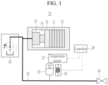
- Druckerhaltungsvorrichtung, die Folgendes umfasst:eine hydraulische Vorrichtung (21) innerhalb eines Gehäuses (12) eines Batteriemoduls zusammen mit einer Vielzahl von Batteriezellen (11), wobei die hydraulische Vorrichtung (21) dafür konfiguriert ist, ihr Volumen zu verändern, um eine Druckveränderung innerhalb des Gehäuses (12) aufgrund einer Verformung der Vielzahl von Batteriezellen (11) auszugleichen,einen Sammler (22), der durch ein Rohr (23) mit der hydraulischen Vorrichtung (21) verbunden ist, wobei der Sammler (22) dafür konfiguriert ist, gemäß einer Veränderung bei einem Volumen der hydraulischen Vorrichtung (21) Fluid zu speichern und das Fluid an das Rohr (23) abzugeben oder das Fluid, das von dem Rohr (23) eingeleitet wird, zu speichern,eine Heizvorrichtung (26), die dafür konfiguriert ist, den Sammler (22) zu erwärmen,umfassend einen Temperatursensor (27), der dafür konfiguriert ist, die Außenlufttemperatur zu erfassen, undeine Steuerung (28), die dafür konfiguriert ist, die Heizvorrichtung (26) gemäß einer Außenlufttemperatur zu steuern.
- Druckerhaltungsvorrichtung nach Anspruch 1, wobei, wenn sich die Vielzahl von Batteriezellen (11) ausdehnt, die hydraulische Vorrichtung (21) dafür konfiguriert ist, sich zusammenzuziehen, um das Fluid an das Rohr (23) abzugeben, und,
wenn sich die Vielzahl von Batteriezellen (11) zusammenzieht, die hydraulische Vorrichtung (21) dafür konfiguriert ist, sich durch das von dem Rohr (23) eingeleitete Fluid auszudehnen. - Druckerhaltungsvorrichtung nach Anspruch 1 oder 2, wobei die hydraulische Vorrichtung (21) einen Hydraulikzylinder oder eine Hydrauliktasche umfasst.
- Druckerhaltungsvorrichtung nach einem der Ansprüche 1 bis 3, die ferner ein Erhaltungsventil (24) umfasst, das mit dem Rohr (23) verbunden ist, und
wobei das Erhaltungsventil (24) dafür konfiguriert ist, geöffnet zu werden, um das Fluid zu dem Rohr (23) zu ergänzen. - Druckerhaltungsvorrichtung nach einem der Ansprüche 1 bis 4, die ferner ein Druckminderungsventil (25) umfasst, das mit dem Rohr (23) verbunden ist, und
wobei das Druckminderungsventil (25) dafür konfiguriert ist, geöffnet zu werden, wenn ein Druck innerhalb des Rohres (23) einen Referenzwert überschreitet, um das Fluid aus dem Rohr (23) abzugeben. - Druckerhaltungsvorrichtung nach einem der Ansprüche 1 bis 4, die ferner Folgendes umfasst:ein Ergänzungsrohr (31),ein Magnetventil (33), das zwischen dem Rohr (23) und dem Ergänzungsrohr (31) angeschlossen und dafür konfiguriert ist, Fluid des Ergänzungsrohres (31) dem Rohr (23) zuzuführen, wenn das Magnetventil (33) geöffnet wird, undeinen Hilfssammler (32), der dafür konfiguriert ist, Fluid zu speichern und das Fluid an das Ergänzungsrohr (31) abzugeben, wenn ein Innendruck des Ergänzungsrohres (31) aufgrund der Öffnung des Magnetventils (33) abnimmt,wobei das Magnetventil (33) dafür konfiguriert ist, geöffnet zu werden, wenn ein Innendruck des Rohres (23) um einen Referenzwert oder mehr niedriger ist als der Innendruck des Ergänzungsrohres (31).
- Druckerhaltungsvorrichtung nach Anspruch 6, die ferner ein Erhaltungsventil (24) umfasst, das mit dem Ergänzungsrohr (31) verbunden ist, und
wobei das Erhaltungsventil (24) dafür konfiguriert ist, geöffnet zu werden, um das Fluid zu dem Ergänzungsrohr (31) zu ergänzen. - Druckerhaltungsvorrichtung nach Anspruch 6 oder 7, die ferner Folgendes umfasst:einen ersten Drucksensor (34), der an das Rohr (23) gekoppelt und dafür konfiguriert ist, den Innendruck des Rohres (23) zu erfassen, undeinen zweiten Drucksensor (35), der an das Ergänzungsrohr (31) gekoppelt und dafür konfiguriert ist, den Innendruck des Ergänzungsrohres (31) zu erfassen,wobei die Steuerung (28) dafür konfiguriert ist, das Magnetventil (33) zu öffnen, wenn ein durch den ersten Drucksensor (34) erfasster erster Druck niedriger ist als ein durch den zweiten Drucksensor (35) erfasster zweiter Druck.
- Druckerhaltungsvorrichtung nach Anspruch 6, 7 oder 8, die Folgendes umfasst:einen ersten Drucksensor (34), der an den Sammler (22) gekoppelt und dafür konfiguriert ist, einen Innendruck des Sammlers (22) zu erfassen, undeinen zweiten Drucksensor (35), der an den Hilfssammler (32) gekoppelt und dafür konfiguriert ist, einen Innendruck des Hilfssammlers (32) zu erfassen,wobei die Steuerung (28) dafür konfiguriert ist, das Magnetventil (33) zu öffnen, wenn ein durch den ersten Drucksensor (34) erfasster erster Druck niedriger ist als ein durch den zweiten Drucksensor (35) erfasster zweiter Druck.
- Druckerhaltungsvorrichtung nach einem der Ansprüche 1 bis 9, die ferner Folgendes umfasst:eine Pumpe (41), die an das Rohr (23) gekoppelt und dafür konfiguriert ist, dem Rohr (23) zusätzliches Fluid zuzuführen, undeinen Motor (42), der dafür konfiguriert ist, die Pumpe (41) anzutreiben,wobei die Steuerung (28) dafür konfiguriert ist, den Motor (42) zu steuern, um die Pumpe (41) anzutreiben, wenn sich ein Innendruck des Rohres (23) bis zu einem Referenzwert oder weniger absenkt.
- Batteriesystem, das Folgendes umfasst:die Druckerhaltungsvorrichtung nach einem der Ansprüche 1 bis 10; unddas Batteriemodul, wobei das Batteriemodul Folgendes umfasst:die Vielzahl von Batteriezellen (11), die zueinander benachbart gestapelt sind, unddas Gehäuse (12), das einen luftdichten Raum aufweist, in dem die Vielzahl von Batteriezellen (11) und die hydraulische Vorrichtung (21) angeordnet sind.
Applications Claiming Priority (1)
| Application Number | Priority Date | Filing Date | Title |
|---|---|---|---|
| KR1020220144581A KR102831003B1 (ko) | 2022-11-02 | 2022-11-02 | 압력 유지 장치 및 이를 포함하는 배터리 시스템 |
Publications (2)
| Publication Number | Publication Date |
|---|---|
| EP4366010A1 EP4366010A1 (de) | 2024-05-08 |
| EP4366010B1 true EP4366010B1 (de) | 2025-07-02 |
Family
ID=88598792
Family Applications (1)
| Application Number | Title | Priority Date | Filing Date |
|---|---|---|---|
| EP23206521.9A Active EP4366010B1 (de) | 2022-11-02 | 2023-10-27 | Druckwartungsvorrichtung und batteriesystem damit |
Country Status (7)
| Country | Link |
|---|---|
| US (1) | US20240145789A1 (de) |
| EP (1) | EP4366010B1 (de) |
| JP (1) | JP7704818B2 (de) |
| KR (1) | KR102831003B1 (de) |
| CN (1) | CN117996384A (de) |
| HU (1) | HUE072374T2 (de) |
| PL (1) | PL4366010T3 (de) |
Families Citing this family (1)
| Publication number | Priority date | Publication date | Assignee | Title |
|---|---|---|---|---|
| TWI902057B (zh) * | 2023-11-15 | 2025-10-21 | 財團法人工業技術研究院 | 電池盒 |
Family Cites Families (7)
| Publication number | Priority date | Publication date | Assignee | Title |
|---|---|---|---|---|
| JP5636634B2 (ja) | 2009-02-25 | 2014-12-10 | トヨタ自動車株式会社 | 電極板加圧装置 |
| JP5257471B2 (ja) * | 2010-12-28 | 2013-08-07 | トヨタ自動車株式会社 | 電池 |
| DE102014206813B4 (de) | 2014-04-09 | 2023-11-16 | Robert Bosch Gmbh | Elektrische Energiespeicher und Verfahren zum Betreiben eines elektrischen Energiespeichers |
| HUE071136T2 (hu) * | 2020-03-27 | 2025-08-28 | Samsung Sdi Co Ltd | Fluidumrugóval nyomás alá helyezett akkumulátorköteg |
| KR102773568B1 (ko) * | 2020-07-22 | 2025-02-27 | 주식회사 엘지에너지솔루션 | 전지 모듈, 전지 모듈 시스템 및 전지 모듈을 포함하는 전지 팩 |
| KR102760165B1 (ko) * | 2020-08-11 | 2025-02-03 | 주식회사 엘지에너지솔루션 | 전지 모듈 모사 시스템 및 방법 |
| DE102021123282A1 (de) * | 2020-09-09 | 2022-03-10 | Sk Innovation Co., Ltd. | Sekundärbatteriemodul mit aktivem druckkissen |
-
2022
- 2022-11-02 KR KR1020220144581A patent/KR102831003B1/ko active Active
-
2023
- 2023-10-11 US US18/485,159 patent/US20240145789A1/en active Pending
- 2023-10-27 EP EP23206521.9A patent/EP4366010B1/de active Active
- 2023-10-27 HU HUE23206521A patent/HUE072374T2/hu unknown
- 2023-10-27 PL PL23206521.9T patent/PL4366010T3/pl unknown
- 2023-11-01 JP JP2023187645A patent/JP7704818B2/ja active Active
- 2023-11-01 CN CN202311443657.0A patent/CN117996384A/zh active Pending
Also Published As
| Publication number | Publication date |
|---|---|
| CN117996384A (zh) | 2024-05-07 |
| HUE072374T2 (hu) | 2025-11-28 |
| KR102831003B1 (ko) | 2025-07-04 |
| KR20240062740A (ko) | 2024-05-09 |
| JP7704818B2 (ja) | 2025-07-08 |
| EP4366010A1 (de) | 2024-05-08 |
| JP2024067017A (ja) | 2024-05-16 |
| PL4366010T3 (pl) | 2025-09-22 |
| US20240145789A1 (en) | 2024-05-02 |
Similar Documents
| Publication | Publication Date | Title |
|---|---|---|
| KR20210122112A (ko) | 전지 시스템 및 그 작동 방법 및 이를 포함하는 전지 팩 및 차량 | |
| JP5083587B2 (ja) | 燃料電池システム及びその温度調整方法 | |
| EP4037079A1 (de) | Batteriemodul, batteriemodulsystem und batteriepack mit einem batteriemodul | |
| KR101868670B1 (ko) | 연료 전지용 엔드 플레이트, 연료 전지 및 연료 전지 시스템 | |
| EP4366010B1 (de) | Druckwartungsvorrichtung und batteriesystem damit | |
| CN101911359A (zh) | 燃料电池系统 | |
| JP4372725B2 (ja) | 燃料電池システム | |
| US8329351B2 (en) | Fuel cell system | |
| US20070026280A1 (en) | Fuel cell system and method of controlling gas pressure in fuel cell system | |
| US11705563B2 (en) | Fuel cell system | |
| US20240291087A1 (en) | Battery Module Housing for a Battery Module, Battery Module, and Electrical Energy Store | |
| US7892688B2 (en) | Fuel cell system running on high pressure gas and process for controlling the system | |
| US11626603B2 (en) | Fuel cell system | |
| US11108064B2 (en) | Fuel cell system mounted on a vehicle | |
| CN113451666B (zh) | 电池系统及其操作方法以及包括其的电池组和车辆 | |
| JP2009212066A (ja) | 燃料電池システム | |
| US20250174808A1 (en) | Battery module | |
| US20250279523A1 (en) | Battery system with compensator | |
| JP2010015733A (ja) | 燃料電池システム、および、圧縮空気供給装置 | |
| KR102906907B1 (ko) | 배터리 시스템 및 그 작동 방법 | |
| US20250293366A1 (en) | Battery module | |
| US20260038906A1 (en) | Systems and methods for battery temperature management | |
| US20250015423A1 (en) | Battery cell pressure control | |
| US20260038942A1 (en) | Modular energy storage system with temperature control | |
| US20220311076A1 (en) | Electrical power control system |
Legal Events
| Date | Code | Title | Description |
|---|---|---|---|
| PUAI | Public reference made under article 153(3) epc to a published international application that has entered the european phase |
Free format text: ORIGINAL CODE: 0009012 |
|
| STAA | Information on the status of an ep patent application or granted ep patent |
Free format text: STATUS: REQUEST FOR EXAMINATION WAS MADE |
|
| 17P | Request for examination filed |
Effective date: 20231027 |
|
| AK | Designated contracting states |
Kind code of ref document: A1 Designated state(s): AL AT BE BG CH CY CZ DE DK EE ES FI FR GB GR HR HU IE IS IT LI LT LU LV MC ME MK MT NL NO PL PT RO RS SE SI SK SM TR |
|
| GRAP | Despatch of communication of intention to grant a patent |
Free format text: ORIGINAL CODE: EPIDOSNIGR1 |
|
| RIC1 | Information provided on ipc code assigned before grant |
Ipc: H01M 50/264 20210101ALI20241220BHEP Ipc: H01M 10/635 20140101ALI20241220BHEP Ipc: H01M 10/42 20060101ALI20241220BHEP Ipc: H01M 10/04 20060101AFI20241220BHEP |
|
| STAA | Information on the status of an ep patent application or granted ep patent |
Free format text: STATUS: GRANT OF PATENT IS INTENDED |
|
| INTG | Intention to grant announced |
Effective date: 20250130 |
|
| GRAS | Grant fee paid |
Free format text: ORIGINAL CODE: EPIDOSNIGR3 |
|
| GRAA | (expected) grant |
Free format text: ORIGINAL CODE: 0009210 |
|
| STAA | Information on the status of an ep patent application or granted ep patent |
Free format text: STATUS: THE PATENT HAS BEEN GRANTED |
|
| AK | Designated contracting states |
Kind code of ref document: B1 Designated state(s): AL AT BE BG CH CY CZ DE DK EE ES FI FR GB GR HR HU IE IS IT LI LT LU LV MC ME MK MT NL NO PL PT RO RS SE SI SK SM TR |
|
| REG | Reference to a national code |
Ref country code: GB Ref legal event code: FG4D |
|
| REG | Reference to a national code |
Ref country code: CH Ref legal event code: EP |
|
| REG | Reference to a national code |
Ref country code: DE Ref legal event code: R096 Ref document number: 602023004504 Country of ref document: DE |
|
| REG | Reference to a national code |
Ref country code: IE Ref legal event code: FG4D |
|
| PGFP | Annual fee paid to national office [announced via postgrant information from national office to epo] |
Ref country code: FR Payment date: 20250930 Year of fee payment: 3 |
|
| REG | Reference to a national code |
Ref country code: NL Ref legal event code: MP Effective date: 20250702 |
|
| REG | Reference to a national code |
Ref country code: HU Ref legal event code: AG4A Ref document number: E072374 Country of ref document: HU |
|
| PG25 | Lapsed in a contracting state [announced via postgrant information from national office to epo] |
Ref country code: PT Free format text: LAPSE BECAUSE OF FAILURE TO SUBMIT A TRANSLATION OF THE DESCRIPTION OR TO PAY THE FEE WITHIN THE PRESCRIBED TIME-LIMIT Effective date: 20251103 |
|
| PGFP | Annual fee paid to national office [announced via postgrant information from national office to epo] |
Ref country code: HU Payment date: 20251105 Year of fee payment: 3 |
|
| PG25 | Lapsed in a contracting state [announced via postgrant information from national office to epo] |
Ref country code: NL Free format text: LAPSE BECAUSE OF FAILURE TO SUBMIT A TRANSLATION OF THE DESCRIPTION OR TO PAY THE FEE WITHIN THE PRESCRIBED TIME-LIMIT Effective date: 20250702 |
|
| REG | Reference to a national code |
Ref country code: AT Ref legal event code: MK05 Ref document number: 1810307 Country of ref document: AT Kind code of ref document: T Effective date: 20250702 |
|
| PG25 | Lapsed in a contracting state [announced via postgrant information from national office to epo] |
Ref country code: IS Free format text: LAPSE BECAUSE OF FAILURE TO SUBMIT A TRANSLATION OF THE DESCRIPTION OR TO PAY THE FEE WITHIN THE PRESCRIBED TIME-LIMIT Effective date: 20251102 |
|
| PGFP | Annual fee paid to national office [announced via postgrant information from national office to epo] |
Ref country code: DE Payment date: 20250930 Year of fee payment: 3 |
|
| PG25 | Lapsed in a contracting state [announced via postgrant information from national office to epo] |
Ref country code: NO Free format text: LAPSE BECAUSE OF FAILURE TO SUBMIT A TRANSLATION OF THE DESCRIPTION OR TO PAY THE FEE WITHIN THE PRESCRIBED TIME-LIMIT Effective date: 20251002 |
|
| REG | Reference to a national code |
Ref country code: LT Ref legal event code: MG9D |
|
| PG25 | Lapsed in a contracting state [announced via postgrant information from national office to epo] |
Ref country code: AT Free format text: LAPSE BECAUSE OF FAILURE TO SUBMIT A TRANSLATION OF THE DESCRIPTION OR TO PAY THE FEE WITHIN THE PRESCRIBED TIME-LIMIT Effective date: 20250702 |
|
| PG25 | Lapsed in a contracting state [announced via postgrant information from national office to epo] |
Ref country code: FI Free format text: LAPSE BECAUSE OF FAILURE TO SUBMIT A TRANSLATION OF THE DESCRIPTION OR TO PAY THE FEE WITHIN THE PRESCRIBED TIME-LIMIT Effective date: 20250702 |
|
| PG25 | Lapsed in a contracting state [announced via postgrant information from national office to epo] |
Ref country code: HR Free format text: LAPSE BECAUSE OF FAILURE TO SUBMIT A TRANSLATION OF THE DESCRIPTION OR TO PAY THE FEE WITHIN THE PRESCRIBED TIME-LIMIT Effective date: 20250702 |
|
| PG25 | Lapsed in a contracting state [announced via postgrant information from national office to epo] |
Ref country code: GR Free format text: LAPSE BECAUSE OF FAILURE TO SUBMIT A TRANSLATION OF THE DESCRIPTION OR TO PAY THE FEE WITHIN THE PRESCRIBED TIME-LIMIT Effective date: 20251003 |
|
| PG25 | Lapsed in a contracting state [announced via postgrant information from national office to epo] |
Ref country code: CZ Free format text: LAPSE BECAUSE OF FAILURE TO SUBMIT A TRANSLATION OF THE DESCRIPTION OR TO PAY THE FEE WITHIN THE PRESCRIBED TIME-LIMIT Effective date: 20250702 Ref country code: SE Free format text: LAPSE BECAUSE OF FAILURE TO SUBMIT A TRANSLATION OF THE DESCRIPTION OR TO PAY THE FEE WITHIN THE PRESCRIBED TIME-LIMIT Effective date: 20250702 |
|
| PG25 | Lapsed in a contracting state [announced via postgrant information from national office to epo] |
Ref country code: LV Free format text: LAPSE BECAUSE OF FAILURE TO SUBMIT A TRANSLATION OF THE DESCRIPTION OR TO PAY THE FEE WITHIN THE PRESCRIBED TIME-LIMIT Effective date: 20250702 |
|
| PG25 | Lapsed in a contracting state [announced via postgrant information from national office to epo] |
Ref country code: BG Free format text: LAPSE BECAUSE OF FAILURE TO SUBMIT A TRANSLATION OF THE DESCRIPTION OR TO PAY THE FEE WITHIN THE PRESCRIBED TIME-LIMIT Effective date: 20250702 |
|
| PGFP | Annual fee paid to national office [announced via postgrant information from national office to epo] |
Ref country code: PL Payment date: 20251014 Year of fee payment: 3 |
|
| PG25 | Lapsed in a contracting state [announced via postgrant information from national office to epo] |
Ref country code: RS Free format text: LAPSE BECAUSE OF FAILURE TO SUBMIT A TRANSLATION OF THE DESCRIPTION OR TO PAY THE FEE WITHIN THE PRESCRIBED TIME-LIMIT Effective date: 20251002 |
|
| PG25 | Lapsed in a contracting state [announced via postgrant information from national office to epo] |
Ref country code: ES Free format text: LAPSE BECAUSE OF FAILURE TO SUBMIT A TRANSLATION OF THE DESCRIPTION OR TO PAY THE FEE WITHIN THE PRESCRIBED TIME-LIMIT Effective date: 20250702 |
|
| PG25 | Lapsed in a contracting state [announced via postgrant information from national office to epo] |
Ref country code: RO Free format text: LAPSE BECAUSE OF FAILURE TO SUBMIT A TRANSLATION OF THE DESCRIPTION OR TO PAY THE FEE WITHIN THE PRESCRIBED TIME-LIMIT Effective date: 20250702 |
|
| PG25 | Lapsed in a contracting state [announced via postgrant information from national office to epo] |
Ref country code: SM Free format text: LAPSE BECAUSE OF FAILURE TO SUBMIT A TRANSLATION OF THE DESCRIPTION OR TO PAY THE FEE WITHIN THE PRESCRIBED TIME-LIMIT Effective date: 20250702 |
|
| PG25 | Lapsed in a contracting state [announced via postgrant information from national office to epo] |
Ref country code: DK Free format text: LAPSE BECAUSE OF FAILURE TO SUBMIT A TRANSLATION OF THE DESCRIPTION OR TO PAY THE FEE WITHIN THE PRESCRIBED TIME-LIMIT Effective date: 20250702 |
|
| PG25 | Lapsed in a contracting state [announced via postgrant information from national office to epo] |
Ref country code: IT Free format text: LAPSE BECAUSE OF FAILURE TO SUBMIT A TRANSLATION OF THE DESCRIPTION OR TO PAY THE FEE WITHIN THE PRESCRIBED TIME-LIMIT Effective date: 20250702 |
|
| PG25 | Lapsed in a contracting state [announced via postgrant information from national office to epo] |
Ref country code: EE Free format text: LAPSE BECAUSE OF FAILURE TO SUBMIT A TRANSLATION OF THE DESCRIPTION OR TO PAY THE FEE WITHIN THE PRESCRIBED TIME-LIMIT Effective date: 20250702 Ref country code: SK Free format text: LAPSE BECAUSE OF FAILURE TO SUBMIT A TRANSLATION OF THE DESCRIPTION OR TO PAY THE FEE WITHIN THE PRESCRIBED TIME-LIMIT Effective date: 20250702 |