EP4366010B1 - Pressure maintenance device and battery system including the same - Google Patents
Pressure maintenance device and battery system including the same Download PDFInfo
- Publication number
- EP4366010B1 EP4366010B1 EP23206521.9A EP23206521A EP4366010B1 EP 4366010 B1 EP4366010 B1 EP 4366010B1 EP 23206521 A EP23206521 A EP 23206521A EP 4366010 B1 EP4366010 B1 EP 4366010B1
- Authority
- EP
- European Patent Office
- Prior art keywords
- pressure
- pipe
- fluid
- accumulator
- maintenance device
- Prior art date
- Legal status (The legal status is an assumption and is not a legal conclusion. Google has not performed a legal analysis and makes no representation as to the accuracy of the status listed.)
- Active
Links
Images


Classifications
-
- H—ELECTRICITY
- H01—ELECTRIC ELEMENTS
- H01M—PROCESSES OR MEANS, e.g. BATTERIES, FOR THE DIRECT CONVERSION OF CHEMICAL ENERGY INTO ELECTRICAL ENERGY
- H01M10/00—Secondary cells; Manufacture thereof
- H01M10/42—Methods or arrangements for servicing or maintenance of secondary cells or secondary half-cells
- H01M10/4207—Methods or arrangements for servicing or maintenance of secondary cells or secondary half-cells for several batteries or cells simultaneously or sequentially
-
- F—MECHANICAL ENGINEERING; LIGHTING; HEATING; WEAPONS; BLASTING
- F15—FLUID-PRESSURE ACTUATORS; HYDRAULICS OR PNEUMATICS IN GENERAL
- F15B—SYSTEMS ACTING BY MEANS OF FLUIDS IN GENERAL; FLUID-PRESSURE ACTUATORS, e.g. SERVOMOTORS; DETAILS OF FLUID-PRESSURE SYSTEMS, NOT OTHERWISE PROVIDED FOR
- F15B1/00—Installations or systems with accumulators; Supply reservoir or sump assemblies
- F15B1/02—Installations or systems with accumulators
- F15B1/04—Accumulators
-
- F—MECHANICAL ENGINEERING; LIGHTING; HEATING; WEAPONS; BLASTING
- F15—FLUID-PRESSURE ACTUATORS; HYDRAULICS OR PNEUMATICS IN GENERAL
- F15B—SYSTEMS ACTING BY MEANS OF FLUIDS IN GENERAL; FLUID-PRESSURE ACTUATORS, e.g. SERVOMOTORS; DETAILS OF FLUID-PRESSURE SYSTEMS, NOT OTHERWISE PROVIDED FOR
- F15B13/00—Details of servomotor systems ; Valves for servomotor systems
- F15B13/02—Fluid distribution or supply devices characterised by their adaptation to the control of servomotors
- F15B13/026—Pressure compensating valves
-
- F—MECHANICAL ENGINEERING; LIGHTING; HEATING; WEAPONS; BLASTING
- F15—FLUID-PRESSURE ACTUATORS; HYDRAULICS OR PNEUMATICS IN GENERAL
- F15B—SYSTEMS ACTING BY MEANS OF FLUIDS IN GENERAL; FLUID-PRESSURE ACTUATORS, e.g. SERVOMOTORS; DETAILS OF FLUID-PRESSURE SYSTEMS, NOT OTHERWISE PROVIDED FOR
- F15B15/00—Fluid-actuated devices for displacing a member from one position to another; Gearing associated therewith
- F15B15/18—Combined units comprising both motor and pump
-
- F—MECHANICAL ENGINEERING; LIGHTING; HEATING; WEAPONS; BLASTING
- F15—FLUID-PRESSURE ACTUATORS; HYDRAULICS OR PNEUMATICS IN GENERAL
- F15B—SYSTEMS ACTING BY MEANS OF FLUIDS IN GENERAL; FLUID-PRESSURE ACTUATORS, e.g. SERVOMOTORS; DETAILS OF FLUID-PRESSURE SYSTEMS, NOT OTHERWISE PROVIDED FOR
- F15B21/00—Common features of fluid actuator systems; Fluid-pressure actuator systems or details thereof, not covered by any other group of this subclass
- F15B21/04—Special measures taken in connection with the properties of the fluid
- F15B21/042—Controlling the temperature of the fluid
- F15B21/0427—Heating
-
- G—PHYSICS
- G05—CONTROLLING; REGULATING
- G05D—SYSTEMS FOR CONTROLLING OR REGULATING NON-ELECTRIC VARIABLES
- G05D16/00—Control of fluid pressure
- G05D16/02—Modifications to reduce the effects of instability, e.g. due to vibrations, friction, abnormal temperature, overloading or imbalance
-
- G—PHYSICS
- G05—CONTROLLING; REGULATING
- G05D—SYSTEMS FOR CONTROLLING OR REGULATING NON-ELECTRIC VARIABLES
- G05D16/00—Control of fluid pressure
- G05D16/20—Control of fluid pressure characterised by the use of electric means
- G05D16/2006—Control of fluid pressure characterised by the use of electric means with direct action of electric energy on controlling means
- G05D16/2066—Control of fluid pressure characterised by the use of electric means with direct action of electric energy on controlling means using controlling means acting on the pressure source
-
- H—ELECTRICITY
- H01—ELECTRIC ELEMENTS
- H01M—PROCESSES OR MEANS, e.g. BATTERIES, FOR THE DIRECT CONVERSION OF CHEMICAL ENERGY INTO ELECTRICAL ENERGY
- H01M10/00—Secondary cells; Manufacture thereof
- H01M10/04—Construction or manufacture in general
- H01M10/0481—Compression means other than compression means for stacks of electrodes and separators
-
- H—ELECTRICITY
- H01—ELECTRIC ELEMENTS
- H01M—PROCESSES OR MEANS, e.g. BATTERIES, FOR THE DIRECT CONVERSION OF CHEMICAL ENERGY INTO ELECTRICAL ENERGY
- H01M10/00—Secondary cells; Manufacture thereof
- H01M10/42—Methods or arrangements for servicing or maintenance of secondary cells or secondary half-cells
- H01M10/48—Accumulators combined with arrangements for measuring, testing or indicating the condition of cells, e.g. the level or density of the electrolyte
- H01M10/482—Accumulators combined with arrangements for measuring, testing or indicating the condition of cells, e.g. the level or density of the electrolyte for several batteries or cells simultaneously or sequentially
-
- H—ELECTRICITY
- H01—ELECTRIC ELEMENTS
- H01M—PROCESSES OR MEANS, e.g. BATTERIES, FOR THE DIRECT CONVERSION OF CHEMICAL ENERGY INTO ELECTRICAL ENERGY
- H01M10/00—Secondary cells; Manufacture thereof
- H01M10/60—Heating or cooling; Temperature control
- H01M10/63—Control systems
- H01M10/635—Control systems based on ambient temperature
-
- H—ELECTRICITY
- H01—ELECTRIC ELEMENTS
- H01M—PROCESSES OR MEANS, e.g. BATTERIES, FOR THE DIRECT CONVERSION OF CHEMICAL ENERGY INTO ELECTRICAL ENERGY
- H01M50/00—Constructional details or processes of manufacture of the non-active parts of electrochemical cells other than fuel cells, e.g. hybrid cells
- H01M50/20—Mountings; Secondary casings or frames; Racks, modules or packs; Suspension devices; Shock absorbers; Transport or carrying devices; Holders
- H01M50/204—Racks, modules or packs for multiple batteries or multiple cells
-
- H—ELECTRICITY
- H01—ELECTRIC ELEMENTS
- H01M—PROCESSES OR MEANS, e.g. BATTERIES, FOR THE DIRECT CONVERSION OF CHEMICAL ENERGY INTO ELECTRICAL ENERGY
- H01M50/00—Constructional details or processes of manufacture of the non-active parts of electrochemical cells other than fuel cells, e.g. hybrid cells
- H01M50/20—Mountings; Secondary casings or frames; Racks, modules or packs; Suspension devices; Shock absorbers; Transport or carrying devices; Holders
- H01M50/262—Mountings; Secondary casings or frames; Racks, modules or packs; Suspension devices; Shock absorbers; Transport or carrying devices; Holders with fastening means, e.g. locks
- H01M50/264—Mountings; Secondary casings or frames; Racks, modules or packs; Suspension devices; Shock absorbers; Transport or carrying devices; Holders with fastening means, e.g. locks for cells or batteries, e.g. straps, tie rods or peripheral frames
-
- F—MECHANICAL ENGINEERING; LIGHTING; HEATING; WEAPONS; BLASTING
- F15—FLUID-PRESSURE ACTUATORS; HYDRAULICS OR PNEUMATICS IN GENERAL
- F15B—SYSTEMS ACTING BY MEANS OF FLUIDS IN GENERAL; FLUID-PRESSURE ACTUATORS, e.g. SERVOMOTORS; DETAILS OF FLUID-PRESSURE SYSTEMS, NOT OTHERWISE PROVIDED FOR
- F15B2201/00—Accumulators
- F15B2201/50—Monitoring, detection and testing means for accumulators
- F15B2201/51—Pressure detection
-
- H—ELECTRICITY
- H01—ELECTRIC ELEMENTS
- H01M—PROCESSES OR MEANS, e.g. BATTERIES, FOR THE DIRECT CONVERSION OF CHEMICAL ENERGY INTO ELECTRICAL ENERGY
- H01M50/00—Constructional details or processes of manufacture of the non-active parts of electrochemical cells other than fuel cells, e.g. hybrid cells
- H01M50/20—Mountings; Secondary casings or frames; Racks, modules or packs; Suspension devices; Shock absorbers; Transport or carrying devices; Holders
- H01M50/233—Mountings; Secondary casings or frames; Racks, modules or packs; Suspension devices; Shock absorbers; Transport or carrying devices; Holders characterised by physical properties of casings or racks, e.g. dimensions
- H01M50/242—Mountings; Secondary casings or frames; Racks, modules or packs; Suspension devices; Shock absorbers; Transport or carrying devices; Holders characterised by physical properties of casings or racks, e.g. dimensions adapted for protecting batteries against vibrations, collision impact or swelling
-
- Y—GENERAL TAGGING OF NEW TECHNOLOGICAL DEVELOPMENTS; GENERAL TAGGING OF CROSS-SECTIONAL TECHNOLOGIES SPANNING OVER SEVERAL SECTIONS OF THE IPC; TECHNICAL SUBJECTS COVERED BY FORMER USPC CROSS-REFERENCE ART COLLECTIONS [XRACs] AND DIGESTS
- Y02—TECHNOLOGIES OR APPLICATIONS FOR MITIGATION OR ADAPTATION AGAINST CLIMATE CHANGE
- Y02E—REDUCTION OF GREENHOUSE GAS [GHG] EMISSIONS, RELATED TO ENERGY GENERATION, TRANSMISSION OR DISTRIBUTION
- Y02E60/00—Enabling technologies; Technologies with a potential or indirect contribution to GHG emissions mitigation
- Y02E60/10—Energy storage using batteries
Definitions
- aspects of embodiments of the present disclosure relate to a pressure maintenance device and a battery system including the same.
- a secondary battery is a battery that is designed to be repeatedly charged and discharged and differs from a primary battery, which is designed to provide an irreversible conversion of chemical energy to electrical energy.
- a low-capacity secondary battery is often used as a power supply for a small electronic device, such as a mobile phone, a laptop computer, or a camcorder, while a high-capacity secondary battery is often used as a power supply for a hybrid vehicle or the like.
- a secondary battery cell includes an electrode assembly including a positive electrode, a negative electrode, and a separator interposed between the positive electrode and the negative electrode, a case accommodating the electrode assembly, and an electrode terminal electrically connected to the electrode assembly.
- An electrolyte solution is injected into the case to enable charging and discharging of the battery cell due to an electrochemical reaction between the positive electrode, the negative electrode, and the electrolyte solution.
- a shape of the case such as a cylindrical or rectangular shape, varies depending on the desired use or application of the battery cell.
- the secondary battery cell repeatedly contracts and expands due to repeated charging and discharging such that a direct fatigue load is applied to a battery structure.
- the secondary battery cell may continuously expand as the electrode assembly deteriorates, and a pressure applied to the battery structure may increase in later life stages of the cell compared with an early life stage of the cell due to the continuous expansion such that a safety problem may occur due to performance degradation and structural deformation.
- US-A-2022077550 discloses a secondary battery module capable of constantly maintaining a surface pressure of a battery cell.
- the secondary battery module of the present invention includes a battery stack in which a plurality of battery cells are stacked; a case in which the battery stack is accommodated; a pressure pad disposed to be in contact with the battery cells constituting the battery stack and having a volume which is adjusted; and a pressure adjusting unit that adjusts the volume of the pressure pad in response to a measured pressure, thereby constantly maintaining the pressure applied to the battery cell.
- Embodiments of the present disclosure provide a pressure maintenance device for maintaining a constant internal pressure of a battery structure even if a volume of a battery cell changes and a battery system including the pressure maintenance device.
- the invention provides a pressure maintenance device and a battery system as set forth in the claims.
- the expression "at least one of a, b, or c" indicates only a, only b, only c, both a and b, both a and c, both b and c, all of a, b, and c, or variations thereof.
- the terms “use,” “using,” and “used” may be considered synonymous with the terms “utilize,” “utilizing,” and “utilized,” respectively.
- the terms “substantially,” “about,” and similar terms are used as terms of approximation and not as terms of degree, and are intended to account for the inherent variations in measured or calculated values that would be recognized by those of ordinary skill in the art.
- spatially relative terms such as “beneath,” “below,” “lower,” “above,” “upper,” and the like, may be used herein for ease of description to describe one element or feature's relationship to another element(s) or feature(s) as illustrated in the figures. It will be understood that the spatially relative terms are intended to encompass different orientations of the device in use or operation in addition to the orientation depicted in the figures. For example, if the device in the figures is turned over, elements described as “below” or “beneath” other elements or features would then be oriented “above” or “over” the other elements or features. Thus, the term “below” may encompass both an orientation of above and below. The device may be otherwise oriented (rotated 90 degrees or at other orientations), and the spatially relative descriptors used herein should be interpreted accordingly.
Landscapes
- Engineering & Computer Science (AREA)
- Chemical & Material Sciences (AREA)
- General Chemical & Material Sciences (AREA)
- Chemical Kinetics & Catalysis (AREA)
- Electrochemistry (AREA)
- Physics & Mathematics (AREA)
- Manufacturing & Machinery (AREA)
- Fluid Mechanics (AREA)
- Mechanical Engineering (AREA)
- General Engineering & Computer Science (AREA)
- Automation & Control Theory (AREA)
- General Physics & Mathematics (AREA)
- Analytical Chemistry (AREA)
- Secondary Cells (AREA)
- Battery Mounting, Suspending (AREA)
Description
- Aspects of embodiments of the present disclosure relate to a pressure maintenance device and a battery system including the same.
- A secondary battery is a battery that is designed to be repeatedly charged and discharged and differs from a primary battery, which is designed to provide an irreversible conversion of chemical energy to electrical energy. A low-capacity secondary battery is often used as a power supply for a small electronic device, such as a mobile phone, a laptop computer, or a camcorder, while a high-capacity secondary battery is often used as a power supply for a hybrid vehicle or the like.
- Generally, a secondary battery cell includes an electrode assembly including a positive electrode, a negative electrode, and a separator interposed between the positive electrode and the negative electrode, a case accommodating the electrode assembly, and an electrode terminal electrically connected to the electrode assembly. An electrolyte solution is injected into the case to enable charging and discharging of the battery cell due to an electrochemical reaction between the positive electrode, the negative electrode, and the electrolyte solution. A shape of the case, such as a cylindrical or rectangular shape, varies depending on the desired use or application of the battery cell.
- The secondary battery cell repeatedly contracts and expands due to repeated charging and discharging such that a direct fatigue load is applied to a battery structure. In addition, the secondary battery cell may continuously expand as the electrode assembly deteriorates, and a pressure applied to the battery structure may increase in later life stages of the cell compared with an early life stage of the cell due to the continuous expansion such that a safety problem may occur due to performance degradation and structural deformation.
-
US-A-2022077550 discloses a secondary battery module capable of constantly maintaining a surface pressure of a battery cell. The secondary battery module of the present invention includes a battery stack in which a plurality of battery cells are stacked; a case in which the battery stack is accommodated; a pressure pad disposed to be in contact with the battery cells constituting the battery stack and having a volume which is adjusted; and a pressure adjusting unit that adjusts the volume of the pressure pad in response to a measured pressure, thereby constantly maintaining the pressure applied to the battery cell. - Embodiments of the present disclosure provide a pressure maintenance device for maintaining a constant internal pressure of a battery structure even if a volume of a battery cell changes and a battery system including the pressure maintenance device.
- The invention provides a pressure maintenance device and a battery system as set forth in the claims.
-
-
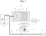
FIG. 1 is a schematic diagram of a battery system including a pressure maintenance device according to embodiments of the present disclosure. -
FIG. 2 is a schematic diagram of a battery system including a pressure maintenance device according to other embodiments of the present disclosure. -
FIG. 3 is a schematic diagram of a battery system including a pressure maintenance device according to other embodiments of the present disclosure. - Embodiments of the present disclosure will now be described, in detail, in connection with the accompanying drawings. Aspects and features of embodiments, and manners of providing the same, will now be described in detail with the accompanying drawings. As those skilled in the art would realize, the described embodiments may be modified in various different ways, all without departing from the scope of the present disclosure. The embodiments are provided as examples so that the present disclosure may be thorough and complete, and will sufficiently describe aspects and features of the present disclosure to a person skilled in the art.
- It will be understood that when an element or layer is referred to as being "on," "connected to," or "coupled to" another element or layer, it may be directly on, connected, or coupled to the other element or layer or one or more intervening elements or layers may also be present. When an element or layer is referred to as being "directly on," "directly connected to," or "directly coupled to" another element or layer, there are no intervening elements or layers present. For example, when a first element is described as being "coupled" or "connected" to a second element, the first element may be directly coupled or connected to the second element or the first element may be indirectly coupled or connected to the second element via one or more intervening elements.
- In the figures, dimensions of the various elements, layers, etc. may be exaggerated for clarity of illustration. The same reference numerals designate the same elements. As used herein, the term "and/or" includes any and all combinations of one or more of the associated listed items. Further, the use of "may" when describing embodiments of the present disclosure relates to "one or more embodiments of the present disclosure." Expressions, such as "at least one of" and "any one of," when preceding a list of elements, modify the entire list of elements and do not modify the individual elements of the list. For example, the expression "at least one of a, b, or c" indicates only a, only b, only c, both a and b, both a and c, both b and c, all of a, b, and c, or variations thereof. As used herein, the terms "use," "using," and "used" may be considered synonymous with the terms "utilize," "utilizing," and "utilized," respectively. As used herein, the terms "substantially," "about," and similar terms are used as terms of approximation and not as terms of degree, and are intended to account for the inherent variations in measured or calculated values that would be recognized by those of ordinary skill in the art.
- It will be understood that, although the terms first, second, third, etc. may be used herein to describe various elements, components, regions, layers, and/or sections, these elements, components, regions, layers, and/or sections should not be limited by these terms. These terms are used to distinguish one element, component, region, layer, or section from another element, component, region, layer, or section. Thus, a first element, component, region, layer, or section discussed below could be termed a second element, component, region, layer, or section without departing from the teachings of example embodiments.
- Spatially relative terms, such as "beneath," "below," "lower," "above," "upper," and the like, may be used herein for ease of description to describe one element or feature's relationship to another element(s) or feature(s) as illustrated in the figures. It will be understood that the spatially relative terms are intended to encompass different orientations of the device in use or operation in addition to the orientation depicted in the figures. For example, if the device in the figures is turned over, elements described as "below" or "beneath" other elements or features would then be oriented "above" or "over" the other elements or features. Thus, the term "below" may encompass both an orientation of above and below. The device may be otherwise oriented (rotated 90 degrees or at other orientations), and the spatially relative descriptors used herein should be interpreted accordingly.
- The terminology used herein is for the purpose of describing embodiments of the present disclosure and is not intended to be limiting of the present disclosure. As used herein, the singular forms "a" and "an" are intended to include the plural forms as well, unless the context clearly indicates otherwise. It will be further understood that the terms "includes," "including," "comprises," and/or "comprising," when used in this specification, specify the presence of stated features, integers, steps, operations, elements, and/or components but do not preclude the presence or addition of one or more other features, integers, steps, operations, elements, components, and/or groups thereof.
- The controller and/or any other relevant devices or components according to embodiments of the present disclosure described herein may be implemented utilizing any suitable hardware, firmware (e.g., an application-specific integrated circuit), software, and/or a suitable combination of software, firmware, and hardware. For example, the various components of the controller may be formed on one integrated circuit (IC) chip or on separate IC chips. Further, the various components of the controller may be implemented on a flexible printed circuit film, a tape carrier package (TCP), a printed circuit board (PCB), or formed on a same substrate as the controller. Further, the various components of the controller may be a process or thread, running on one or more processors, in one or more computing devices, executing computer program instructions and interacting with other system components for performing the various functionalities described herein. The computer program instructions are stored in a memory which may be implemented in a computing device using a standard memory device, such as, for example, a random access memory (RAM). The computer program instructions may also be stored in other non-transitory computer readable media such as, for example, a CD-ROM, flash drive, or the like. Also, a person of skill in the art should recognize that the functionality of various computing devices may be combined or integrated into a single computing device or the functionality of a particular computing device may be distributed across one or more other computing devices without departing from the scope of the embodiments of the present disclosure.
- Hereinafter, a pressure maintenance device, according to embodiments of the present disclosure, and a battery system including the pressure maintenance device will be described, in detail, with reference to necessary drawings.
-
FIG. 1 is a schematic diagram of a battery system including a pressure maintenance device according to embodiments of the present disclosure. - Referring to
FIG. 1 , the battery system 1a, according to an embodiment, may include a battery module and a pressure maintenance device of the battery module. - The battery module may include a plurality of
battery cells 11 connected to each other in series and/or in parallel and amodule housing 12 that is a structure accommodating the plurality ofbattery cells 11. The plurality ofbattery cells 11 may be disposed in a stacked arrangement inside themodule housing 12. - An airtight space (e.g., an inner space or a compartment) 14 may be formed inside the
module housing 12. The plurality ofbattery cells 11 and ahydraulic device 21 of a pressure maintenance device 20, described in more detail below, may be accommodated in theinner space 14 of themodule housing 12. Abuffer plate 13 may be arranged between thehydraulic device 21 and thebattery cells 11 in theinner space 14 of themodule housing 12. Thebuffer plate 13 may be deformed or moved according to a change in a volume of one or more of thebattery cells 11. Thebuffer plate 13 may be moved or deformed toward thebattery cells 11 due to an expansion pressure from thehydraulic device 21 if thebattery cells 11 contract. Thebuffer plate 13 may be moved or deformed toward thehydraulic device 21 due to an expansion pressure of thebattery cells 11 during expansion of thebattery cells 11. - The pressure maintenance device, according to an embodiment, may include the
hydraulic device 21, anaccumulator 22, afluid pipe 23, amaintenance valve 24, apressure reducing valve 25, aheater 26, atemperature sensor 27, and acontroller 28. - The
hydraulic device 21 may reduce or minimize a fatigue load of themodule housing 12 by offsetting (e.g., canceling) pressure change inside themodule housing 12 due to deformation (e.g., a change in the volume) of thebattery cells 11. If thebattery cells 11 contract (e.g., if one or more of thebattery cells 11 contract), thehydraulic device 21 may expand to move or deform thebuffer plate 13 toward thebattery cells 11. If thebattery cells 11 expand, thehydraulic device 21 may contract by the expansion pressure transferred from thebattery cells 11 through thebuffer plate 13. - The
hydraulic device 21 may include a device (e.g., a hydraulic bag, a hydraulic cylinder, or the like) configured to expand and contract in response to a hydraulic pressure. Thehydraulic device 21 may expand or contract through inflow and discharge of fluid (e.g., oil). If thehydraulic device 21 contracts, the fluid may be discharged from thehydraulic device 21. If thehydraulic device 21 expands, the fluid may flow into thehydraulic device 21. - The
accumulator 22 may store a pressurized fluid and may offset a hydraulic pressure change caused by expansion and contraction of thehydraulic device 21. For example, if a hydraulic pressure change occurs inside thefluid pipe 23 due to the expansion or the contraction of thehydraulic device 21, theaccumulator 22 may discharge the fluid to thefluid pipe 23 or may offset the hydraulic pressure change within thefluid pipe 23 by introducing the fluid of thefluid pipe 23 into theaccumulator 22. If thebattery cells 11 contract such that thehydraulic device 21 expands, theaccumulator 22 may prevent a decrease in a hydraulic pressure by discharging the fluid to thefluid pipe 23. If thebattery cells 11 expand so that thehydraulic device 21 contracts, theaccumulator 22 may prevent an increase in the hydraulic pressure by introducing the fluid from thehydraulic device 21 into theaccumulator 22. In some embodiments, an internal pressure of theaccumulator 22 may change in proportion to a change in an internal pressure of thebattery cells 11. For example, if the internal pressure of thebattery cells 11 increases (e.g., thebattery cells 11 expand), a pressure of theaccumulator 22 may increase due to inflow of the fluid, and if the internal pressure of thebattery cells 11 decrease (e.g., thebattery cells 11 contract), the pressure of theaccumulator 22 may decrease due to discharge of the fluid. - The
fluid pipe 23 may extend through (or extend into) and may be coupled to themodule housing 12. Thefluid pipe 23 may be respectively connected to a fluid inlet/outlet of thehydraulic device 21 and a fluid inlet/outlet of theaccumulator 22. Thefluid pipe 23 may be a passage for fluid exchange between thehydraulic device 21 and theaccumulator 22. - The
maintenance valve 24 may be connected to a fluid inlet of thefluid pipe 23 to replenish the fluid inside thefluid pipe 23. Themaintenance valve 24 may be manually or automatically operated. - The
maintenance valve 24 may be opened by a manual operation of a user to supply the fluid to the inside of thefluid pipe 23. - Opening and closing of the
maintenance valve 24 may be controlled by thecontroller 28. For example, if a pressure inside thefluid pipe 23 lowers to a reference (or predetermined) value or less or a set period is reached, thecontroller 28 may open themaintenance valve 24 so that a fluid stored in a fluid tank is supplied to the inside of thefluid pipe 23. In some embodiments, the pressure maintenance device may further include a pressure sensor 34 (see, e.g.,FIG. 2 ) configured to detect an internal pressure of thefluid pipe 23 or theaccumulator 22. If the internal pressure of thefluid pipe 23 or theaccumulator 22 detected by the pressure sensor lowers to the reference value or less, thecontroller 28 may open themaintenance valve 24 so that an additional fluid is supplied to thefluid pipe 23. - The
pressure reducing valve 25 may be connected to a fluid outlet of thefluid pipe 23 to discharge the fluid inside thefluid pipe 23 to the outside of thefluid pipe 23. Thepressure reducing valve 25 may be opened if the pressure inside thefluid pipe 23 exceeds a reference (or predetermined) value so that the fluid inside thefluid pipe 23 is discharged to the outside. Thepressure reducing valve 25 may be closed if the pressure inside thefluid pipe 23 lowers to the reference value or less to stop the discharging of the fluid. - The
fluid pipe 23 may maintain an airtight state except for when themaintenance valve 24 is opened so that the fluid is supplied to the inside of thefluid pipe 23 or if thepressure reducing valve 25 is opened so that the fluid inside thefluid pipe 23 is discharged to the outside. In some embodiments, when themaintenance valve 24 and thepressure reducing valve 25 are both closed, the fluid inside thefluid pipe 23 may be exchanged only between thehydraulic device 21 and theaccumulator 22. - The
heater 26 may heat theaccumulator 22. - The
temperature sensor 27 measures an outdoor air temperature (e.g., an outdoor temperature, an external or ambient temperature) outside theaccumulator 22. - The
controller 28 may detect the outdoor air temperature through thetemperature sensor 27 and may adjust an electric current flowing through theheater 26 so that the heater heats theaccumulator 22. To prevent a pressure change inside theaccumulator 22 from occurring due to a temperature change inside theaccumulator 22, thecontroller 28 may reduce or minimize a change in an internal temperature of theaccumulator 22 by controlling an operation of theheater 26 according to the detected outdoor air temperature. Because energy necessary to raise 1 L nitrogen pressurized at 200 bar by 30 degrees Celsius is approximately 2 Wh (watt-hours) if nitrogen is charged inside theaccumulator 22, a temperature change inside theaccumulator 22 may be reduced or minimized with little energy. - According to the above-described embodiments, displacement of the
battery cells 11 may be absorbed by the pressure maintenance device so that a fatigue load applied to themodule housing 12 due to charging and discharging of thebattery cells 11 is reduced or minimized. For example, even if swelling occurs due to deterioration during the life of thebattery cells 11, a pressure inside themodule housing 12 may be kept constant compared with an early life stage of thebattery cells 11 so that structural deformation of themodule housing 12 is reduced or minimized. In some embodiments, if the battery module is installed, a fastening force of thebattery cells 11 may be improved by pressurizing thebattery cells 11 by using the pressure maintenance device. In some embodiments, theaccumulator 22, theheater 26, and the like may be used to respond to an external temperature variable, fluid leakage, or the like. -
FIG. 2 is a schematic diagram of a battery system including a pressure maintenance device according to other embodiments of the present disclosure. - The same reference numerals used to describe the
battery system 1b shown inFIG. 2 as those used to describe the battery system 1a shown inFIG. 1 , described above, may denote the same component and a redundant description thereof is omitted. - Comparing the embodiment shown in
FIG. 2 with the embodiment shown inFIG. 1 , thebattery system 1b may further include asupplemental pipe 31, an auxiliary accumulator (e.g., a supplemental accumulator) 32, a solenoid valve 33, andpressure sensors - The
supplemental pipe 31 may be a fluid passage between the solenoid valve 33, theauxiliary accumulator 32, and themaintenance valve 24. - The
auxiliary accumulator 32 may store a fluid in a pressurized state. If the fluid is supplied to thesupplemental pipe 31 through themaintenance valve 24, theauxiliary accumulator 32 may store the supplied fluid therein. If the solenoid valve 33 is opened so that a hydraulic pressure inside thesupplemental pipe 31 lowers, theauxiliary accumulator 32 may supply the fluid to thesupplemental pipe 31 by discharging the fluid stored in theauxiliary accumulator 32. - Opening of the solenoid valve 33 may be controlled by the
controller 28, and flow of the fluid between thefluid pipe 23 and thesupplemental pipe 31 may be controlled. - The
pressure sensor 34 may be coupled to thefluid pipe 23 to detect an internal hydraulic pressure P1 of thefluid pipe 23. Thepressure sensor 35 may be coupled to thesupplemental pipe 31 to detect an internal hydraulic pressure P2 of thesupplemental pipe 31. - The
controller 28 may compare the pressures detected by thepressure sensors fluid pipe 23 is lower than the internal hydraulic pressure P2 of thesupplemental pipe 31, may open the solenoid valve 33 so that the fluid of thesupplemental pipe 31 flows into thefluid pipe 23. If the fluid is supplied from thesupplemental pipe 31 to thefluid pipe 23, the hydraulic pressure inside thesupplemental pipe 31 may be lowered so that the fluid stored in theaccumulator 32 is discharged to thesupplemental pipe 31. - In the above description, the opening of the solenoid valve 33 is controlled by using the
pressure sensors fluid pipe 23 and thesupplemental pipe 31, but this is merely an example. In another embodiment, thepressure sensors accumulators pressure sensors accumulator 22 and theauxiliary accumulator 32, and thecontroller 28 may compare the internal pressures to determine whether the solenoid valve 33 should be opened. In some embodiments, if the internal pressure of theaccumulator 22 becomes lower than the internal pressure of theauxiliary accumulator 32, thecontroller 28 may open the solenoid valve 33 so that the fluid of thesupplemental pipe 31 flows into thefluid pipe 23. - According to embodiments of the present disclosure, the
auxiliary accumulator 32 may be used to supplement the fluid if a pressure of an accumulator (e.g., a main or primary accumulator) 22 decreases so that a maintenance period is increased. -
FIG. 3 is a schematic diagram of a battery system including a pressure maintenance device according to embodiments of the present disclosure. - The same reference numerals used to describe the
battery system 1c shown inFIG. 3 as are used to describe the battery system 1a shown inFIG. 1 , described above, may denote the same component and a redundant description thereof is omitted. - Comparing the embodiment shown in
FIG. 3 with the embodiment shown inFIG. 1 , thebattery system 1c may further include apump 41 for supplementing the fluid in thefluid pipe 23 and amotor 42 for driving thepump 41 instead of themaintenance valve 24. - If a pressure inside the
fluid pipe 23 lowers to a reference (or predetermined) value or less or a set period is reached, thecontroller 28 may drive thepump 41 by using (or by controlling) themotor 42 so that a fluid stored in a fluid tank is supplied to the inside of thefluid pipe 23. In some embodiments, the pressure maintenance device may further include the pressure sensor 34 (see, e.g.,FIG. 2 ) for detecting an internal pressure of thefluid pipe 23 or theaccumulator 22. If the internal pressure of thefluid pipe 23 or theaccumulator 22 detected by the pressure sensor lowers to the reference value or less, thecontroller 28 may drive thepump 41 so that additional fluid is supplied to thefluid pipe 23. - According to embodiments of the present disclosure, if the pressure maintenance device determines that fluid supplement is necessary to maintain pressure, the pressure maintenance device may drive the
pump 41 to automatically supplement the fluid in theaccumulator 22 even during driving of a vehicle to which the battery system is attached. - While embodiments of the present disclosure have been shown and described with reference to the accompanying drawings, the specific terms used herein are only for the purpose of describing these embodiments and are not intended to define the meanings thereof or be limiting of the scope of the present disclosure set forth in the claims. Therefore, a person of ordinary skill in the art will understand that various modifications and other equivalent embodiments of the present disclosure are possible. Consequently, the scope of the present disclosure must be determined based on the appended claims.
Description of Some Reference Symbols 1a, 1b, 1c: battery system 11: battery cell 12: module housing 13: buffer plate 21: hydraulic device 22: accumulator 23: fluid pipe 24: maintenance valve 25: pressure reducing valve 26: heater 27: temperature sensor 28: controller 31: supplemental pipe 32: auxiliary accumulator 33: solenoid valve 34, 35: pressure sensor 41: pump 42: motor FIG. 2 ) for detecting an internal pressure of thefluid pipe 23 or theaccumulator 22. If the internal pressure of thefluid pipe 23 or theaccumulator 22 detected by the pressure sensor lowers to the reference value or less, thecontroller 28 may drive thepump 41 so that additional fluid is supplied to thefluid pipe 23. - According to embodiments of the present disclosure, if the pressure maintenance device determines that fluid supplement is necessary to maintain pressure, the pressure maintenance device may drive the
pump 41 to automatically supplement the fluid in theaccumulator 22 even during driving of a vehicle to which the battery system is attached. - While embodiments of the present disclosure have been shown and described with reference to the accompanying drawings, the specific terms used herein are only for the purpose of describing these embodiments and are not intended to define the meanings thereof. Therefore, a person of ordinary skill in the art will understand that various modifications and other equivalent embodiments of the present disclosure are possible. Consequently, the scope of the present disclosure must be determined based on the appended claims.
Description of Some Reference Symbols 1a, 1b, 1c: battery system 11: battery cell 12: module housing 13: buffer plate 21: hydraulic device 22: accumulator 23: fluid pipe 24: maintenance valve 25: pressure reducing valve 26: heater 27: temperature sensor 28: controller 31: supplemental pipe 32: auxiliary accumulator 33: solenoid valve 34, 35: pressure sensor 41: pump 42: motor
Claims (11)
- A pressure maintenance device comprising:a hydraulic device (21) inside a housing (12) of a battery module together with a plurality of battery cells (11), the hydraulic device (21) being configured to change its volume to offset a pressure change inside the housing (12) due to deformation of the plurality of battery cells (11);an accumulator (22) connected to the hydraulic device (21) through a pipe (23), the accumulator (22) being configured to store fluid and to discharge the fluid to the pipe (23) or to store the fluid introduced from the pipe (23) according to a change in a volume of the hydraulic device (21);a heater (26) configured to heat the accumulator (22)comprising a temperature sensor (27) configured to detect the outdoor air temperature; anda controller (28) configured to control the heater (26) according to an outdoor air temperature.
- The pressure maintenance device as claimed in claim 1, wherein, when the plurality of battery cells (11) expand, the hydraulic device (21) is configured to contract to discharge the fluid to the pipe (23), and
when the plurality of battery cells (11) contract, the hydraulic device (21) is configured to expand by the fluid introduced from the pipe (23). - The pressure maintenance device as claimed in claim 1 or 2, wherein the hydraulic device (21) comprises a hydraulic cylinder or a hydraulic bag.
- The pressure maintenance device as claimed in any one of claims 1 to 3, further comprising a maintenance valve (24) connected to the pipe (23), and
wherein the maintenance valve (24) is configured to be opened to supplement the fluid to the pipe (23). - The pressure maintenance device as claimed in any one of claims 1 to 4, further comprising a pressure reducing valve (25) connected to the pipe (23), and
wherein the pressure reducing valve (25) is configured to be opened when a pressure inside the pipe (23) exceeds a reference value to discharge the fluid from the pipe (23). - The pressure maintenance device as claimed in any one of claims 1 to 4, further comprising:a supplemental pipe (31);a solenoid valve (33) connected between the pipe (23) and the supplemental pipe (31) and configured to supply fluid of the supplemental pipe (31) to the pipe (23) when the solenoid valve (33) is opened; andan auxiliary accumulator (32) configured to store fluid and to discharge the fluid to the supplemental pipe (31) when an internal pressure of the supplemental pipe (31) decreases due to the opening of the solenoid valve (33),wherein the solenoid valve (33) is configured to be opened when an internal pressure of the pipe (23) is lower than the internal pressure of the supplemental pipe (31) by a reference value or more.
- The pressure maintenance device as claimed in claim 6, further comprising a maintenance valve (24) connected to the supplemental pipe (31), and
wherein the maintenance valve (24) is configured to be opened to supplement the fluid to the supplemental pipe (31). - The pressure maintenance device as claimed in claim 6 or 7, further comprising:a first pressure sensor (34) coupled to the pipe (23) and configured to detect the internal pressure of the pipe (23); anda second pressure sensor (35) coupled to the supplemental pipe (31) and configured to detect the internal pressure of the supplemental pipe (31),wherein the controller (28) is configured to open the solenoid valve (33) when a first pressure detected by the first pressure sensor (34) is lower than a second pressure detected by the second pressure sensor (35).
- The pressure maintenance device as claimed in claim 6, 7, or 8, comprising:a first pressure sensor (34) coupled to the accumulator (22) and configured to detect an internal pressure of the accumulator (22); anda second pressure sensor (35) coupled to the auxiliary accumulator (32) and configured to detect an internal pressure of the auxiliary accumulator (32),wherein the controller (28) is configured to open the solenoid valve (33) when a first pressure detected by the first pressure sensor (34) is lower than a second pressure detected by the second pressure sensor (35).
- The pressure maintenance device as claimed in any one of claims 1 to 9, further comprising:a pump (41) coupled to the pipe (23) and configured to supply additional fluid to the pipe (23); anda motor (42) configured to drive the pump (41),wherein the controller (28) is configured to control the motor (42) to drive the pump (41) when an internal pressure of the pipe (23) lowers to a reference value or less.
- A battery system comprising:the pressure maintenance device according to any one of claims 1 to 10; andthe battery module, the battery module comprising:the plurality of battery cells (11) stacked adjacent to each other; andthe housing (12) having an airtight space in which the plurality of battery cells (11) and the hydraulic device (21) are arranged.
Applications Claiming Priority (1)
| Application Number | Priority Date | Filing Date | Title |
|---|---|---|---|
| KR1020220144581A KR102831003B1 (en) | 2022-11-02 | 2022-11-02 | Pressure maintenance device and battery system including the same |
Publications (2)
| Publication Number | Publication Date |
|---|---|
| EP4366010A1 EP4366010A1 (en) | 2024-05-08 |
| EP4366010B1 true EP4366010B1 (en) | 2025-07-02 |
Family
ID=88598792
Family Applications (1)
| Application Number | Title | Priority Date | Filing Date |
|---|---|---|---|
| EP23206521.9A Active EP4366010B1 (en) | 2022-11-02 | 2023-10-27 | Pressure maintenance device and battery system including the same |
Country Status (7)
| Country | Link |
|---|---|
| US (1) | US20240145789A1 (en) |
| EP (1) | EP4366010B1 (en) |
| JP (1) | JP7704818B2 (en) |
| KR (1) | KR102831003B1 (en) |
| CN (1) | CN117996384A (en) |
| HU (1) | HUE072374T2 (en) |
| PL (1) | PL4366010T3 (en) |
Families Citing this family (1)
| Publication number | Priority date | Publication date | Assignee | Title |
|---|---|---|---|---|
| TWI902057B (en) * | 2023-11-15 | 2025-10-21 | 財團法人工業技術研究院 | Battery box |
Family Cites Families (7)
| Publication number | Priority date | Publication date | Assignee | Title |
|---|---|---|---|---|
| JP5636634B2 (en) | 2009-02-25 | 2014-12-10 | トヨタ自動車株式会社 | Electrode plate pressurizing device |
| JP5257471B2 (en) * | 2010-12-28 | 2013-08-07 | トヨタ自動車株式会社 | battery |
| DE102014206813B4 (en) | 2014-04-09 | 2023-11-16 | Robert Bosch Gmbh | Electrical energy storage and method for operating an electrical energy storage |
| EP3886202B1 (en) * | 2020-03-27 | 2025-02-19 | Samsung SDI Co., Ltd. | Fluid spring pressurized battery stack |
| KR102773568B1 (en) * | 2020-07-22 | 2025-02-27 | 주식회사 엘지에너지솔루션 | Battery module, battery module system and battery pack including the battery module |
| KR102760165B1 (en) * | 2020-08-11 | 2025-02-03 | 주식회사 엘지에너지솔루션 | Battery module simulation system and method |
| KR20220033210A (en) * | 2020-09-09 | 2022-03-16 | 에스케이온 주식회사 | Secondary Battery Module with Active Pressure Pad |
-
2022
- 2022-11-02 KR KR1020220144581A patent/KR102831003B1/en active Active
-
2023
- 2023-10-11 US US18/485,159 patent/US20240145789A1/en active Pending
- 2023-10-27 EP EP23206521.9A patent/EP4366010B1/en active Active
- 2023-10-27 HU HUE23206521A patent/HUE072374T2/en unknown
- 2023-10-27 PL PL23206521.9T patent/PL4366010T3/en unknown
- 2023-11-01 JP JP2023187645A patent/JP7704818B2/en active Active
- 2023-11-01 CN CN202311443657.0A patent/CN117996384A/en active Pending
Also Published As
| Publication number | Publication date |
|---|---|
| EP4366010A1 (en) | 2024-05-08 |
| CN117996384A (en) | 2024-05-07 |
| KR20240062740A (en) | 2024-05-09 |
| KR102831003B1 (en) | 2025-07-04 |
| PL4366010T3 (en) | 2025-09-22 |
| US20240145789A1 (en) | 2024-05-02 |
| HUE072374T2 (en) | 2025-11-28 |
| JP7704818B2 (en) | 2025-07-08 |
| JP2024067017A (en) | 2024-05-16 |
Similar Documents
| Publication | Publication Date | Title |
|---|---|---|
| KR20210122112A (en) | Battery system and method for operating the same and battery pack and vehicle including the same | |
| CN101911359B (en) | Fuel cell system | |
| JP5083587B2 (en) | Fuel cell system and temperature adjustment method thereof | |
| EP4037079A1 (en) | Battery module, battery module system, and battery pack comprising battery module | |
| KR101868670B1 (en) | End plate for fuel cell, fuel cell, and fuel cell system | |
| EP4366010B1 (en) | Pressure maintenance device and battery system including the same | |
| JP4372725B2 (en) | Fuel cell system | |
| US11611095B2 (en) | Fuel cell system | |
| US8329351B2 (en) | Fuel cell system | |
| US7968241B2 (en) | Fuel cell system and method of controlling gas pressure in fuel cell system | |
| US11705563B2 (en) | Fuel cell system | |
| US20240291087A1 (en) | Battery Module Housing for a Battery Module, Battery Module, and Electrical Energy Store | |
| US7892688B2 (en) | Fuel cell system running on high pressure gas and process for controlling the system | |
| US11626603B2 (en) | Fuel cell system | |
| EP1427047B1 (en) | Method for controlling flow rate of oxidizer in fuel cell system | |
| US11108064B2 (en) | Fuel cell system mounted on a vehicle | |
| US20240304897A1 (en) | Direct hydrostatic compression system for battery modules of an electric vehicle | |
| US20250174808A1 (en) | Battery module | |
| US20250279523A1 (en) | Battery system with compensator | |
| JP2010015733A (en) | Fuel cell system and compressed air supply device | |
| CN113451666B (en) | Battery system and operating method thereof, and battery pack and vehicle including the same | |
| KR102906907B1 (en) | Battery system and operating method thereof | |
| EP4618244A1 (en) | Battery module | |
| US20260038906A1 (en) | Systems and methods for battery temperature management | |
| US20250015423A1 (en) | Battery cell pressure control |
Legal Events
| Date | Code | Title | Description |
|---|---|---|---|
| PUAI | Public reference made under article 153(3) epc to a published international application that has entered the european phase |
Free format text: ORIGINAL CODE: 0009012 |
|
| STAA | Information on the status of an ep patent application or granted ep patent |
Free format text: STATUS: REQUEST FOR EXAMINATION WAS MADE |
|
| 17P | Request for examination filed |
Effective date: 20231027 |
|
| AK | Designated contracting states |
Kind code of ref document: A1 Designated state(s): AL AT BE BG CH CY CZ DE DK EE ES FI FR GB GR HR HU IE IS IT LI LT LU LV MC ME MK MT NL NO PL PT RO RS SE SI SK SM TR |
|
| GRAP | Despatch of communication of intention to grant a patent |
Free format text: ORIGINAL CODE: EPIDOSNIGR1 |
|
| RIC1 | Information provided on ipc code assigned before grant |
Ipc: H01M 50/264 20210101ALI20241220BHEP Ipc: H01M 10/635 20140101ALI20241220BHEP Ipc: H01M 10/42 20060101ALI20241220BHEP Ipc: H01M 10/04 20060101AFI20241220BHEP |
|
| STAA | Information on the status of an ep patent application or granted ep patent |
Free format text: STATUS: GRANT OF PATENT IS INTENDED |
|
| INTG | Intention to grant announced |
Effective date: 20250130 |
|
| GRAS | Grant fee paid |
Free format text: ORIGINAL CODE: EPIDOSNIGR3 |
|
| GRAA | (expected) grant |
Free format text: ORIGINAL CODE: 0009210 |
|
| STAA | Information on the status of an ep patent application or granted ep patent |
Free format text: STATUS: THE PATENT HAS BEEN GRANTED |
|
| AK | Designated contracting states |
Kind code of ref document: B1 Designated state(s): AL AT BE BG CH CY CZ DE DK EE ES FI FR GB GR HR HU IE IS IT LI LT LU LV MC ME MK MT NL NO PL PT RO RS SE SI SK SM TR |
|
| REG | Reference to a national code |
Ref country code: GB Ref legal event code: FG4D |
|
| REG | Reference to a national code |
Ref country code: CH Ref legal event code: EP |
|
| REG | Reference to a national code |
Ref country code: DE Ref legal event code: R096 Ref document number: 602023004504 Country of ref document: DE |
|
| REG | Reference to a national code |
Ref country code: IE Ref legal event code: FG4D |
|
| PGFP | Annual fee paid to national office [announced via postgrant information from national office to epo] |
Ref country code: FR Payment date: 20250930 Year of fee payment: 3 |
|
| REG | Reference to a national code |
Ref country code: NL Ref legal event code: MP Effective date: 20250702 |
|
| REG | Reference to a national code |
Ref country code: HU Ref legal event code: AG4A Ref document number: E072374 Country of ref document: HU |
|
| PG25 | Lapsed in a contracting state [announced via postgrant information from national office to epo] |
Ref country code: PT Free format text: LAPSE BECAUSE OF FAILURE TO SUBMIT A TRANSLATION OF THE DESCRIPTION OR TO PAY THE FEE WITHIN THE PRESCRIBED TIME-LIMIT Effective date: 20251103 |
|
| PGFP | Annual fee paid to national office [announced via postgrant information from national office to epo] |
Ref country code: HU Payment date: 20251105 Year of fee payment: 3 |
|
| PG25 | Lapsed in a contracting state [announced via postgrant information from national office to epo] |
Ref country code: NL Free format text: LAPSE BECAUSE OF FAILURE TO SUBMIT A TRANSLATION OF THE DESCRIPTION OR TO PAY THE FEE WITHIN THE PRESCRIBED TIME-LIMIT Effective date: 20250702 |
|
| REG | Reference to a national code |
Ref country code: AT Ref legal event code: MK05 Ref document number: 1810307 Country of ref document: AT Kind code of ref document: T Effective date: 20250702 |
|
| PG25 | Lapsed in a contracting state [announced via postgrant information from national office to epo] |
Ref country code: IS Free format text: LAPSE BECAUSE OF FAILURE TO SUBMIT A TRANSLATION OF THE DESCRIPTION OR TO PAY THE FEE WITHIN THE PRESCRIBED TIME-LIMIT Effective date: 20251102 |
|
| PGFP | Annual fee paid to national office [announced via postgrant information from national office to epo] |
Ref country code: DE Payment date: 20250930 Year of fee payment: 3 |
|
| PG25 | Lapsed in a contracting state [announced via postgrant information from national office to epo] |
Ref country code: NO Free format text: LAPSE BECAUSE OF FAILURE TO SUBMIT A TRANSLATION OF THE DESCRIPTION OR TO PAY THE FEE WITHIN THE PRESCRIBED TIME-LIMIT Effective date: 20251002 |
|
| REG | Reference to a national code |
Ref country code: LT Ref legal event code: MG9D |
|
| PG25 | Lapsed in a contracting state [announced via postgrant information from national office to epo] |
Ref country code: AT Free format text: LAPSE BECAUSE OF FAILURE TO SUBMIT A TRANSLATION OF THE DESCRIPTION OR TO PAY THE FEE WITHIN THE PRESCRIBED TIME-LIMIT Effective date: 20250702 |
|
| PG25 | Lapsed in a contracting state [announced via postgrant information from national office to epo] |
Ref country code: FI Free format text: LAPSE BECAUSE OF FAILURE TO SUBMIT A TRANSLATION OF THE DESCRIPTION OR TO PAY THE FEE WITHIN THE PRESCRIBED TIME-LIMIT Effective date: 20250702 |
|
| PG25 | Lapsed in a contracting state [announced via postgrant information from national office to epo] |
Ref country code: HR Free format text: LAPSE BECAUSE OF FAILURE TO SUBMIT A TRANSLATION OF THE DESCRIPTION OR TO PAY THE FEE WITHIN THE PRESCRIBED TIME-LIMIT Effective date: 20250702 |
|
| PG25 | Lapsed in a contracting state [announced via postgrant information from national office to epo] |
Ref country code: GR Free format text: LAPSE BECAUSE OF FAILURE TO SUBMIT A TRANSLATION OF THE DESCRIPTION OR TO PAY THE FEE WITHIN THE PRESCRIBED TIME-LIMIT Effective date: 20251003 |
|
| PG25 | Lapsed in a contracting state [announced via postgrant information from national office to epo] |
Ref country code: CZ Free format text: LAPSE BECAUSE OF FAILURE TO SUBMIT A TRANSLATION OF THE DESCRIPTION OR TO PAY THE FEE WITHIN THE PRESCRIBED TIME-LIMIT Effective date: 20250702 Ref country code: SE Free format text: LAPSE BECAUSE OF FAILURE TO SUBMIT A TRANSLATION OF THE DESCRIPTION OR TO PAY THE FEE WITHIN THE PRESCRIBED TIME-LIMIT Effective date: 20250702 |
|
| PG25 | Lapsed in a contracting state [announced via postgrant information from national office to epo] |
Ref country code: LV Free format text: LAPSE BECAUSE OF FAILURE TO SUBMIT A TRANSLATION OF THE DESCRIPTION OR TO PAY THE FEE WITHIN THE PRESCRIBED TIME-LIMIT Effective date: 20250702 |
|
| PG25 | Lapsed in a contracting state [announced via postgrant information from national office to epo] |
Ref country code: BG Free format text: LAPSE BECAUSE OF FAILURE TO SUBMIT A TRANSLATION OF THE DESCRIPTION OR TO PAY THE FEE WITHIN THE PRESCRIBED TIME-LIMIT Effective date: 20250702 |
|
| PGFP | Annual fee paid to national office [announced via postgrant information from national office to epo] |
Ref country code: PL Payment date: 20251014 Year of fee payment: 3 |
|
| PG25 | Lapsed in a contracting state [announced via postgrant information from national office to epo] |
Ref country code: RS Free format text: LAPSE BECAUSE OF FAILURE TO SUBMIT A TRANSLATION OF THE DESCRIPTION OR TO PAY THE FEE WITHIN THE PRESCRIBED TIME-LIMIT Effective date: 20251002 |
|
| PG25 | Lapsed in a contracting state [announced via postgrant information from national office to epo] |
Ref country code: ES Free format text: LAPSE BECAUSE OF FAILURE TO SUBMIT A TRANSLATION OF THE DESCRIPTION OR TO PAY THE FEE WITHIN THE PRESCRIBED TIME-LIMIT Effective date: 20250702 |