EP4365450A1 - Monitoring apparatus and monitoring method for ship steering engine - Google Patents
Monitoring apparatus and monitoring method for ship steering engine Download PDFInfo
- Publication number
- EP4365450A1 EP4365450A1 EP22832565.0A EP22832565A EP4365450A1 EP 4365450 A1 EP4365450 A1 EP 4365450A1 EP 22832565 A EP22832565 A EP 22832565A EP 4365450 A1 EP4365450 A1 EP 4365450A1
- Authority
- EP
- European Patent Office
- Prior art keywords
- monitoring
- steering gear
- hydraulic actuator
- abnormality
- operating
- Prior art date
- Legal status (The legal status is an assumption and is not a legal conclusion. Google has not performed a legal analysis and makes no representation as to the accuracy of the status listed.)
- Pending
Links
Images




Classifications
-
- B—PERFORMING OPERATIONS; TRANSPORTING
- B63—SHIPS OR OTHER WATERBORNE VESSELS; RELATED EQUIPMENT
- B63B—SHIPS OR OTHER WATERBORNE VESSELS; EQUIPMENT FOR SHIPPING
- B63B79/00—Monitoring properties or operating parameters of vessels in operation
- B63B79/30—Monitoring properties or operating parameters of vessels in operation for diagnosing, testing or predicting the integrity or performance of vessels
-
- B—PERFORMING OPERATIONS; TRANSPORTING
- B63—SHIPS OR OTHER WATERBORNE VESSELS; RELATED EQUIPMENT
- B63B—SHIPS OR OTHER WATERBORNE VESSELS; EQUIPMENT FOR SHIPPING
- B63B79/00—Monitoring properties or operating parameters of vessels in operation
- B63B79/10—Monitoring properties or operating parameters of vessels in operation using sensors, e.g. pressure sensors, strain gauges or accelerometers
-
- B—PERFORMING OPERATIONS; TRANSPORTING
- B63—SHIPS OR OTHER WATERBORNE VESSELS; RELATED EQUIPMENT
- B63H—MARINE PROPULSION OR STEERING
- B63H25/00—Steering; Slowing-down otherwise than by use of propulsive elements; Dynamic anchoring, i.e. positioning vessels by means of main or auxiliary propulsive elements
- B63H25/02—Initiating means for steering, for slowing down, otherwise than by use of propulsive elements, or for dynamic anchoring
- B63H25/04—Initiating means for steering, for slowing down, otherwise than by use of propulsive elements, or for dynamic anchoring automatic, e.g. reacting to compass
-
- B—PERFORMING OPERATIONS; TRANSPORTING
- B63—SHIPS OR OTHER WATERBORNE VESSELS; RELATED EQUIPMENT
- B63H—MARINE PROPULSION OR STEERING
- B63H25/00—Steering; Slowing-down otherwise than by use of propulsive elements; Dynamic anchoring, i.e. positioning vessels by means of main or auxiliary propulsive elements
- B63H25/06—Steering by rudders
- B63H25/08—Steering gear
- B63H25/14—Steering gear power assisted; power driven, i.e. using steering engine
- B63H25/18—Transmitting of movement of initiating means to steering engine
- B63H25/22—Transmitting of movement of initiating means to steering engine by fluid means
-
- B—PERFORMING OPERATIONS; TRANSPORTING
- B63—SHIPS OR OTHER WATERBORNE VESSELS; RELATED EQUIPMENT
- B63H—MARINE PROPULSION OR STEERING
- B63H25/00—Steering; Slowing-down otherwise than by use of propulsive elements; Dynamic anchoring, i.e. positioning vessels by means of main or auxiliary propulsive elements
- B63H25/06—Steering by rudders
- B63H25/08—Steering gear
- B63H25/14—Steering gear power assisted; power driven, i.e. using steering engine
- B63H25/18—Transmitting of movement of initiating means to steering engine
- B63H25/24—Transmitting of movement of initiating means to steering engine by electrical means
-
- B—PERFORMING OPERATIONS; TRANSPORTING
- B63—SHIPS OR OTHER WATERBORNE VESSELS; RELATED EQUIPMENT
- B63H—MARINE PROPULSION OR STEERING
- B63H25/00—Steering; Slowing-down otherwise than by use of propulsive elements; Dynamic anchoring, i.e. positioning vessels by means of main or auxiliary propulsive elements
- B63H25/06—Steering by rudders
- B63H25/08—Steering gear
- B63H25/14—Steering gear power assisted; power driven, i.e. using steering engine
- B63H25/26—Steering engines
- B63H25/28—Steering engines of fluid type
- B63H25/30—Steering engines of fluid type hydraulic
-
- F—MECHANICAL ENGINEERING; LIGHTING; HEATING; WEAPONS; BLASTING
- F04—POSITIVE - DISPLACEMENT MACHINES FOR LIQUIDS; PUMPS FOR LIQUIDS OR ELASTIC FLUIDS
- F04B—POSITIVE-DISPLACEMENT MACHINES FOR LIQUIDS; PUMPS
- F04B49/00—Control, e.g. of pump delivery, or pump pressure of, or safety measures for, machines, pumps, or pumping installations, not otherwise provided for, or of interest apart from, groups F04B1/00 - F04B47/00
- F04B49/06—Control using electricity
-
- F—MECHANICAL ENGINEERING; LIGHTING; HEATING; WEAPONS; BLASTING
- F04—POSITIVE - DISPLACEMENT MACHINES FOR LIQUIDS; PUMPS FOR LIQUIDS OR ELASTIC FLUIDS
- F04B—POSITIVE-DISPLACEMENT MACHINES FOR LIQUIDS; PUMPS
- F04B51/00—Testing machines, pumps, or pumping installations
Definitions
- the present disclosure relates to a monitoring device that monitors the state of a marine steering gear and a method of monitoring the state of the marine steering gear.
- a marine steering gear including a hydraulic actuator that rotates a rudder stock, coupled to a rudder plate, through a tiller has been known.
- the hydraulic actuator includes a pair of hydraulic cylinders for each tiller, and the marine steering gear includes a hydraulic circuit that controls the operation of these hydraulic cylinders.
- the hydraulic circuit includes closed circuits each of which supplies operating oil from a hydraulic pump to the hydraulic actuator and discharges the operating oil from the hydraulic actuator to the hydraulic pump, and one of the closed circuits is used, or two of the closed circuits are used at the same time.
- PTL 1 discloses this type of marine steering gear.
- the hydraulic actuator that operates the tiller is driven by two hydraulic circuits that are a first hydraulic circuit and a second hydraulic circuit.
- Each hydraulic circuit includes a hydraulic switching valve that switches passages of operating oil. The presence or absence of the occurrence of hydraulic lock in the hydraulic circuit is detected based on comparison between the operation of the hydraulic switching valve and a command signal supplied to an electromagnetic valve that operates the hydraulic switching valve.
- the hydraulic lock occurs, the occurrence of the hydraulic lock is informed.
- a steerer immediately stops the hydraulic circuit corresponding to this informing of the abnormality.
- the steering gear of PTL 1 can specify the hydraulic circuit in which the hydraulic lock has occurred, from the two hydraulic circuits, but the operation of stopping this hydraulic system is performed by the steerer. Moreover, PTL 1 does not disclose that when one of the two hydraulic circuits stops, the other is started.
- the marine steering gear may include two or more pump assemblies for each hydraulic actuator.
- at least one pump assembly is in a stop state.
- the pump assembly in a stop state is started instead.
- Such operation of starting or stopping the pump assembly has been performed by the steerer.
- the inventors of the present application are considering automatic switching of the operating pump assembly in order to realize automatic driving of the marine steering gear. Therefore, the pump assemblies are required to be appropriately operated instead of simple switching in which the operation of the abnormal pump assembly is stopped, and the pump assembly in a stop state is started instead.
- a monitoring device of a marine steering gear according to the present disclosure is a monitoring device of a marine steering gear, the marine steering gear including:
- a method of monitoring a marine steering gear is a method of monitoring a marine steering gear, the marine steering gear including:
- the present disclosure provides a technology of appropriately switching pump assemblies in a marine steering gear including a hydraulic actuator and the pump assemblies including respective hydraulic pumps connected to the hydraulic actuator.
- FIG. 1 is a diagram showing a schematic configuration of a marine steering gear 1 and its monitoring device 8 according to Embodiment 1 of the present disclosure.
- a ship 10 includes the marine steering gear 1, the monitoring device 8 that monitors the state of the marine steering gear 1, and a marine steering gear controller 6 that steers the marine steering gear 1.
- the marine steering gear 1 includes a rudder plate 21, a rudder stock 22 coupled to the rudder plate 21, and a hydraulic actuator 3 that rotates the rudder stock 22.
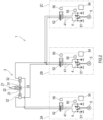
- FIG. 2 is a hydraulic circuit diagram of the marine steering gear 1 according to Embodiment 1.
- the hydraulic actuator 3 according to the present embodiment is of a one-ram two-cylinder type that rotates the rudder stock 22 through a tiller 23 fixed to the rudder stock 22.
- the hydraulic actuator 3 includes a rod-shaped ram 31 and a pair of cylinders 32.
- the ram 31 extends in a direction orthogonal to an axial direction of the rudder stock 22. Both ends of the ram 31 are inserted into the respective cylinders 32.
- a pin 33 is located at the middle of the ram 31 and engages with the tiller 23.
- the hydraulic actuator 3 supplies operating oil to the cylinders 32 or discharges the operating oil from the cylinders 32 in accordance with a steering command from the marine steering gear controller 6 to move the ram 31 and thereby turn the rudder stock 22.
- the marine steering gear 1 includes four pump assemblies that are first to fourth pump assemblies 2A, 2B, 2C, and 2D as pressure sources that operate the hydraulic actuator 3.
- first to fourth pump assemblies 2A, 2B, 2C, and 2D are not especially distinguished from each other, each of these is simply referred to as a "pump assembly 2" by omitting its alphabetical letter.
- the number of pump assemblies 2 for each hydraulic actuator 3 may be two or more and is not limited to the present embodiment.
- Each of the pump assemblies 2 is connected to the hydraulic actuator 3 by a hydraulic circuit such that a closed circuit is formed between the pump assembly 2 and the hydraulic actuator 3.
- the pump assemblies 2 are substantially the same in configuration as each other.
- FIG. 2 shows three pump assemblies that are the first to third pump assemblies 2A, 2B, and 2C each connected to the hydraulic actuator 3 by the closed circuit, and the fourth pump assembly 2D is not shown.
- FIG. 2 merely shows one example of the hydraulic circuit in which the pump assemblies 2 are connected to the hydraulic actuator 3, and the configuration of the hydraulic circuit is not limited to FIG. 2 .
- each of the pump assemblies 2 is connected to the hydraulic actuator 3 by the closed circuit in the hydraulic circuit of the present disclosure, each of the pump assemblies 2 may be connected to the hydraulic actuator 3 by an open circuit.
- Each of the pump assemblies 2 includes a hydraulic pump 4, an electric motor 5 that drives the hydraulic pump 4, and an oil block valve 52 that switches between blocking and allowing of the flow of the operating oil between the hydraulic pump 4 and the hydraulic actuator 3.
- the hydraulic pump 4 is a hydraulic pump of an axial piston type in which pistons are held by a rotating cylinder block so as to be able to reciprocate.
- the hydraulic pump 4 supplies the operating oil to one of the pair of cylinders 32 and collects the operating oil from the other.
- the hydraulic pump 4 according to the present embodiment is a swash plate pump of a variable displacement type in which a swash plate can tilt in both directions from a center. A tilt direction and angle of the swash plate are changed by a regulator 55 in accordance with an output from an assembly controller 54 that operates upon reception of a command of the marine steering gear controller 6.
- the electric motor 5 drives the hydraulic pump 4.
- the start and stop of the electric motor 5 are controlled by the marine steering gear controller 6.
- a rotational frequency of the electric motor 5 is constant.
- the hydraulic pump 4 may be a bent axis pump of a variable displacement type.
- the hydraulic pump 4 may be of a fixed displacement type, the electric motor 5 may be a servomotor, and the rotational direction and rotational frequency of the hydraulic pump 4 may be changed in accordance with the output from the assembly controller 54.
- the hydraulic pump 4 includes a pair of supply/discharge ports, and supply/discharge lines 41 are connected to the respective supply/discharge ports.
- the pair of supply/discharge lines 41 are connected to the respective cylinders 32. This forms the closed circuit between the hydraulic actuator 3 and the hydraulic pump 4.
- tank lines 51 are connected to the respective supply/discharge lines 41.
- Check valves are located on the respective tank lines 51.
- the supply/discharge lines 41 of one pump assembly 2 may be independent from the supply/discharge lines 41 of another pump assembly 2, or the pump assemblies 2 may share part of the supply/discharge line 41.
- the oil block valve 52 is located on the pair of supply/discharge lines 41.
- the oil block valve 52 switches from an unloaded state at a neutral position to an operation position by an unloading valve 56 that operates by control of the assembly controller 54.
- the oil block valve 52 receives pilot pressure to switch from the neutral position to the operation position.
- the pair of supply/discharge lines 41 are connected to each other in a bypass manner such that the operating oil from the hydraulic pump 4 flows to the hydraulic pump 4 or the tank line 51 without being supplied to the hydraulic actuator 3.
- the flow of the operating oil from the hydraulic actuator 3 to the hydraulic pump 4 is blocked by check valves.
- the marine steering gear 1 includes gauges 44 that detect or measure various pieces of information indicating the states of the marine steering gear 1.
- each of the pump assemblies 2 of the marine steering gear 1 includes at least one of: a voltage sensor that measures the voltage of a power supply; a rotational frequency sensor that detects the rotational frequency of the electric motor 5; a hydraulic sensor that measures the pressure of the hydraulic circuit; a connection sensor for control communication; a connection sensor for monitoring communication; a hydraulic lock detector that detects the hydraulic lock; an oil temperature sensor that detects the temperature of the operating oil; a level sensor that detects an oil level in a tank; a dropping amount sensor that detects the amount of oil dropping from the cylinder 32; a temperature sensor that detects the temperature of a controller; and a valve sensor that detects the operating state of a valve.
- the marine steering gear 1 includes: a rudder angle sensor that detects a rotation angle of the rudder stock 22 or the rudder plate 21; and a vibration sensor that detect
- the state of the marine steering gear 1 configured as above is monitored by the monitoring device 8.
- the monitoring device 8 regards the pump assemblies 2A, 2B, 2C, and 2D as monitoring targets.
- the monitoring device 8 may regard the hydraulic actuator 3 as the monitoring target.
- the monitoring targets of the monitoring device 8 are not limited to these.
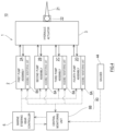
- FIG. 3 is a diagram showing a schematic configuration of the monitoring device 8.
- the monitoring device 8 includes a processing device 81 and a storage 82 connected to the processing device 81 such that the processing device 81can write and read information in and from the storage 82.
- the storage 82, the gauges 44, the marine steering gear controller 6, the assembly controllers 54 of the pump assemblies 2, and the like are connected to the processing device 81.
- the monitoring device 8 acquires detection signals (including measured values and analytical results) from the gauges 44.
- the processing device 81 includes a processor and serves as an abnormality detector 811, a point arithmetic processor 812, and a state change determiner 813 in such a manner that the processor reads and executes predetermined application programs.
- the abnormality detector 811 detects the abnormality of the marine steering gear 1 based on the detection signals (measured values) acquired from the gauges 44. Items of the abnormality which may be detected by the abnormality detector 811 are shown in Table 1 below.
- the abnormality detector 811 may detect the abnormality by a known method. For example, based on the detection signal of the voltage sensor that measures the power supply voltage, the abnormality detector 811 can detect a decrease in the power supply voltage, an increase in the power supply voltage, or an abnormality in which the power supply voltage has exceeded an operating limit. For example, the abnormality detector 811 compares the measured value with a predetermined threshold and detects the abnormality when the measured value exceeds or falls below the predetermined threshold.
- the abnormality detector 811 When the abnormality detector 811 detects the abnormality, the abnormality detector 811 outputs abnormality detection information including the item of the detected abnormality, a place where the abnormality has occurred, a time at which the abnormality has occurred, and the like, to the point arithmetic processor 812. For example, the place where the abnormality has occurred is classified into: the hydraulic actuator 3; a steering main body including the rudder stock 22 and the tiller 23; the first to fourth pump assemblies 2A, 2B, 2C, and 2D; and the like.
- the abnormality detector 811 may be independent from the monitoring device 8.
- the marine steering gear controller 6 may have an abnormality detecting function, and the abnormality detected by the marine steering gear controller 6 may be transmitted to the monitoring device 8.
- the point arithmetic processor 812 that has acquired the abnormality detection information utilizes abnormality item-abnormality point information defining a relation between the item of the abnormality and an abnormality point to derive the abnormality point corresponding to the item of the detected abnormality.
- the abnormality item-abnormality point information is prestored in a memory included in the point arithmetic processor 812 or in the storage 82.
- the abnormality points show abnormality levels of various abnormalities related to the marine steering gear 1 based on a common scale and are indexes showing the abnormality levels.
- the abnormality point may be a value that increases or decreases so as to correspond to the abnormality level. In the present embodiment, the abnormality point is shown by an integer.
- the point arithmetic processor 812 outputs the abnormality detection information further including the abnormality point to the state change determiner 813.
- the state change determiner 813 that has acquired the abnormality detection information calculates state levels of the monitoring targets.
- the state level of the preceding monitoring target is stored in the storage 82.
- the state change determiner 813 reads the state level of the preceding monitoring target from the storage 82.
- the state change determiner 813 adds the abnormality point to the read state level of the preceding monitoring target to obtain a changed state level.
- the state change determiner 813 stores the changed state level in the storage 82. Thus, the state level stored in the storage 82 is updated.
- the state change determiner 813 determines based on the changed state levels in accordance with a predetermined rule whether to operate or stop the operating monitoring target.
- the monitoring target is the pump assembly 2
- whether to set the operating monitoring target to a hot standby state or a cold standby state may be determined instead of determining whether to stop the operating monitoring target.
- Both of the hot standby state and the cold standby state are classified into the stop state.
- the hot standby state is a state where the hydraulic pump 4 is operating but is maintained such that the operating oil does not flow to the hydraulic actuator 3.
- the cold standby state is a state where the hydraulic pump 4 stops, and the operating oil does not flow to the hydraulic actuator 3.
- the state change determiner 813 may select the monitoring target to be started instead, based on the changed state level in accordance with a predetermined rule.
- the rule based on which whether to operate or stop the monitoring target is determined and the rule based on which the monitoring target to be started instead is selected can be set arbitrarily.
- the state change determiner 813 stores in the storage 82 the result of the determination regarding whether to operate or stop the operating monitoring target.
- information that identifies the selected monitoring target is also stored in the storage 82.
- the state change determiner 813 when it is determined to stop the operating monitoring target, the state change determiner 813 outputs a switching signal to the marine steering gear controller 6.
- the switching signal may include identification information of the monitoring target to be stopped and identification information of the monitoring target to be started.
- the state change determiner 813 may output the switching signal to the monitoring target to be switched to be started or stopped. Based on this switching signal, the monitoring target to be stopped is stopped, and the monitoring target to be started is started.
- the monitoring target is the pump assembly 2, and there is the pump assembly 2 to be switched to the hot standby state, the pump assembly 2 as the target is switched from the cold standby state to the hot standby state.
- the state change determiner 813 may inform of the identification information of the monitoring target to be stopped and the identification information of the monitoring target to be started, through a display output device, such as a monitor display located at a bridge of the ship. In this case, a ship operator who has received this informing may manually switch the monitoring target.
- processing of the monitoring device 8 will be described by using specific cases.
- the monitoring targets of the monitoring device 8 are the first to fourth pump assemblies 2A, 2B, 2C, and 2D.
- Table 2 shows preceding state levels, abnormality points, changed state levels, and operating states of the first to fourth pump assemblies 2A, 2B, 2C, and 2D in Case 1.
- Table 2 First Pump Assembly 2A Second Pump Assembly 2B Third Pump Assembly 2C Fourth Pump Assembly 2D Preceding State Level 0.1 1.2 0.3 0.4 Abnormality Point 1.0 - - - Changed State Level 1.1 1.2 0.3 0.4 Operating State Operate ⁇ Stop Stop Stop Stop ⁇ Operate Stop
- the preceding state levels of the first to fourth pump assemblies are respectively 0.1, 1.2, 0.3, and 0.4.
- the value of an integer part of the state level indicates the accumulated abnormality point.
- the value of a decimal part of the state level is any value indicating priority regarding the start. The higher the priority regarding the start is, the smaller the value of the decimal part of the state level is. For example, the value of the decimal part of the state level of the pump assembly 2 that is being maintained and therefore cannot be used is "9" indicating the lowest priority regarding the start.
- the values of the decimal parts of the state levels are the same as each other, there is no order of priority regarding the start, or these are the same in the order of priority regarding the start as each other.
- a first rule is set such that: the changed state level of the operating pump assembly 2 is compared with the changed state levels of the pump assemblies 2 that are in a stop state; in a case where the former is higher than the latter, "operation stop” is determined; and in cases other than the above case, "operation continuation” is determined.
- the first rule is a rule used to determine whether to operate or stop the monitoring target when the monitoring target is the pump assembly 2. Since the changed state level of the operating first pump assembly 2A is higher than each of the changed state levels of the third pump assembly 2C and the fourth pump assembly 2D that are in a stop state, the state change determiner 813 determines the operation stop.
- a second rule is set such that the pump assembly 2 having the lowest changed state level among the pump assemblies 2 in a stop state is selected as the pump assembly 2 to be started instead.
- the second rule is a rule used to selected the pump assembly 2 to be started instead when the monitoring targets are the pump assemblies 2. Since the state level of the third pump assembly 2C is the lowest among the pump assemblies 2 in a stop state, the state change determiner 813 selects the third pump assembly 2C.
- one of the pump assemblies 2 in a stop state is selected as the pump assembly 2 to be started.
- the number of pump assemblies 2 to be stopped and the number of pump assemblies 2 to be started do not necessarily have to be the same as each other.
- the second rule in Cases 1 and 2 when one pump assembly 2 stops, two pump assemblies 2 that have low state levels among the pump assemblies 2 in a stop state may be selected.
- the second rule of Case 1 may be such that when one pump assembly 2 stops, the pump assembly 2 having the lowest state level among the pump assemblies 2 in a stop state is selected as the pump assembly 2 to be started, and the pump assembly 2 having the second lowest state level is selected as the pump assembly 2 to be stopped (hot standby).
- the monitoring targets of the monitoring device 8 are the first to fourth pump assemblies 2A, 2B, 2C, and 2D.
- Table 3 shows the preceding state levels, abnormality points, changed state levels, and operating states of the first to fourth pump assemblies 2A, 2B, 2C, and 2D in Case 2.
- Table 3 First Pump Assembly 2A Second Pump Assembly 2B Third Pump Assembly 2C Fourth Pump Assembly 2D Preceding State Level 0.1 2.2 2.3 2.4 Abnormality Point 1.0 - - - Changed State Level 1.1 2.2 2.3 2.4 Operating State Operate Stop Stop Stop Stop Stop Stop Stop Stop Stop Stop Stop Stop Stop Stop Stop Stop Stop Stop Stop Stop Stop Stop Stop Stop Stop Stop Stop Stop Stop Stop Stop Stop Stop Stop Stop Stop Stop Stop Stop Stop Stop Stop Stop Stop Stop Stop Stop Stop Stop Stop Stop Stop Stop Stop Stop Stop Stop Stop Stop Stop Stop Stop Stop Stop Stop Stop Stop Stop Stop Stop Stop Stop Stop Stop Stop Stop Stop Stop Stop Stop Stop Stop Stop Stop Stop Stop Stop Stop Stop Stop Stop Stop Stop Stop Stop Stop Stop Stop Stop Stop Stop Stop Stop Stop Stop Stop Stop Stop Stop Stop Stop Stop Stop Stop Stop
- the preceding operating states in Case 2 only the first pump assembly 2A is operating, and the second pump assembly 2B, the third pump assembly 2C, and the fourth pump assembly 2D are in a stop state.
- the preceding state levels of the first to fourth pump assemblies are respectively 0.1, 2.2, 2.3, and 2.4.
- the changed state levels of the first to fourth pump assemblies are respectively 1.1, 2.2, 2.3, and 2.4.
- the state change determiner 813 uses the first rule that is the same as that in Case 1. Since the changed state level of the first pump assembly 2A is lower than each of the changed state levels of the pump assemblies 2B, 2C, and 2D in a stop state, the state change determiner 813 determines the operation continuation.
- the monitoring targets of the monitoring device 8 are the first to fourth pump assemblies 2A, 2B, 2C, and 2D.
- Table 4 shows the preceding state levels, abnormality points, changed state levels, and operating states of the first to fourth pump assemblies 2A, 2B, 2C, and 2D in Case 3.
- Table 4 First Pump Assembly 2A Second Pump Assembly 2B Third Pump Assembly 2C Fourth Pump Assembly 2D Preceding State Level 1.1 2.2 1.4 2.3 Abnormality Point 0.6 0.1 0.1 0.1 Changed State Level 1.7 2.3 1.5 2.4 Operating State Operate ⁇ Stop Stop Stop ⁇ Operate Stop
- the state change determiner 813 may periodically (for example, once in several months) calculate the changed state level to which an operating time point has been added, and may monitor the state of the marine steering gear 1 based on this changed state level.
- the operating time point is a value based on a cumulative operating time of the monitoring target. The value of the operating time point increases as the cumulative operating time increases.
- the cumulative operating time of the monitoring target may be measured by the gauges 44 or may be counted by a timer included in the marine steering gear controller 6.
- the operating time point may be a value that increases like a linear function or a quadratic function with respect to the cumulative operating time.
- the storage 82 stores the cumulative operating times of the respective pump assemblies 2 and information indicating a relation between the cumulative operating time and the operating time point.
- the state change determiner 813 can calculate cumulative operation points of the respective pump assemblies 2 by using these pieces of information.
- the preceding state levels of the first to fourth pump assemblies are respectively 1.1, 2.2, 1.4, and 2.3.
- the state change determiner 813 adds the operating time point to the preceding state level.
- the changed state levels of the first to fourth pump assemblies are respectively 1.7, 2.3, 1.5, and 2.4.
- the state change determiner 813 uses the first rule and the second rule which are the same as those in Case 1. Since the changed state level of the third pump assembly 2C in a stop state is lower than the changed state level of the first pump assembly 2A, the state change determiner 813 determines the operation stop. Moreover, since the changed state level of the third pump assembly 2C is the lowest, the monitoring device 8 selects the third pump assembly 2C.
- the first rule is set such that the changed state level of the operating pump assembly 2 and the changed state level of the pump assembly 2 in a stop state are compared with each other.
- the first rule may be set such that the changed state level of the operating pump assembly 2 and a predetermined threshold are compared with each other.
- the first rule may be set such that: in a case where the changed state level of the operating pump assembly 2 exceeds a predetermined threshold (for example, 3), "stop" is determined; and in cases other than the above case, "operation continuation" is determined.
- a predetermined threshold for example, 3
- FIG. 4 is a diagram showing a schematic configuration of the marine steering gear 1 and its monitoring device 80 according to Modified Example 1 of Embodiment 1 of the present disclosure.
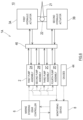
- FIG. 5 is a diagram showing a schematic configuration of the monitoring device 80 according to Modified Example 1 of Embodiment 1.
- the same reference signs are used for components that are the same as or similar to those in Embodiment 1, and detailed explanations thereof are omitted.
- the monitoring device 80 of the marine steering gear 1 according to Modified Example 1 is different from that in Embodiment 1. Since the configuration of the marine steering gear 1 is substantially the same as that in Embodiment 1, a detailed explanation of the marine steering gear 1 is omitted.
- the monitoring device 80 includes: assembly monitoring units 8Alocated at the respective pump assemblies 2; and a central monitoring unit 8B communicable with the assembly monitoring units 8A.
- Various gauges 44 may be located independently from the assembly monitoring units 8A or may be located in the assembly monitoring units 8A.
- Each assembly monitoring unit 8A includes the functions of the abnormality detector 811 and the point arithmetic processor 812.
- the functions of the abnormality detector 811 and the point arithmetic processor 812 are substantially the same as those in Embodiment 1.
- the assembly monitoring unit 8A located at the pump assembly 2 detects the abnormality of the pump assembly 2, calculates the abnormality point corresponding to the detected abnormality, and transmits the abnormality detection information including the abnormality point to the central monitoring unit 8B.
- the assembly monitoring unit 8A located at the first pump assembly 2A detects the abnormality of the first pump assembly 2A, calculates the abnormality point corresponding to the detected abnormality, and transmits the abnormality detection information including the abnormality point to the central monitoring unit 8B.
- the central monitoring unit 8B includes the function of the state change determiner 813.
- the function of the state change determiner 813 is substantially the same as that in Embodiment 1.
- the central monitoring unit 8B acquires the abnormality detection information from the assembly monitoring units 8A, calculates the changed state levels, and determines based on the changed state levels in accordance with the first rule whether to stop or operate the operating pump assembly 2. Moreover, when it is determined to stop the operating pump assembly 2, the central monitoring unit 8B selects the pump assembly 2 to be started instead, based on the changed state levels in accordance with the second rule.
- the central monitoring unit 8B When it is determined to stop the operating pump assembly 2, the central monitoring unit 8B outputs the switching signal to the marine steering gear controller 6 and/or the pump assembly 2 that is a target to be started or stopped. Based on this switching signal, the pump assembly 2 as the target to be stopped is stopped, and the pump assembly 2 as the target to be started is started.
- FIG. 6 is a diagram showing a schematic configuration of a marine steering gear 1A and its monitoring device 8 according to Embodiment 2 of the present disclosure.
- FIG. 7 is a hydraulic circuit diagram of the marine steering gear 1A according to Embodiment 2.
- the same reference signs are used for components that are the same as or similar to those in Embodiment 1, and detailed explanations thereof are omitted.
- the marine steering gear 1A is of a two-ram four-cylinder type and includes two hydraulic actuators that are a first hydraulic actuator 3A and a second hydraulic actuator 3B for one rudder stock 22.
- Each of the first hydraulic actuator 3A and the second hydraulic actuator 3B includes the rod-shaped ram 31 and the pair of cylinders 32.
- the ram 31 extends in a direction orthogonal to the axial direction of the rudder stock 22. Both ends of the ram 31 are inserted into the respective cylinders 32.
- the pin 33 is located at the middle of the ram 31 and engages with the tiller 23 fixed to the rudder stock 22.
- the marine steering gear 1A includes four pump assemblies 2A, 2B, 2C, and 2D as pressure sources that operate the first hydraulic actuator 3A and the second hydraulic actuator 3B.
- the number of pump assemblies 2 with respect to the two hydraulic actuators 3A and 3B may be two or more and is not limited to the present embodiment.
- Each pump assembly 2 is connected to the first hydraulic actuator 3A and the second hydraulic actuator 3B by the hydraulic circuit such that a closed circuit is formed among the pump assembly 2, the first hydraulic actuator 3A, and the second hydraulic actuator 3B. Since the configuration of the pump assembly 2 is substantially the same as that in Embodiment 1, an explanation thereof is omitted.
- FIG. 7 shows three pump assemblies that are the first, second, and third pump assemblies 2A, 2B, and 2C connected to the hydraulic actuators 3A and 3B by the closed circuits, and the fourth pump assembly 2D is not shown.
- FIG. 7 merely shows one example of the hydraulic circuit in which the pump assemblies 2 are connected to the two hydraulic actuators 3A and 3B, and the configuration of the hydraulic circuit is not limited to FIG. 7 .
- the hydraulic circuit includes an actuator switching device 46 to switch between the operation and stop of each of the first hydraulic actuator 3A and the second hydraulic actuator 3B.
- the actuator switching device 46 can switch a connection configuration of the hydraulic circuit to a state where the first hydraulic actuator 3A and the second hydraulic actuator 3B are used, a state where only the first hydraulic actuator 3A is used, or a state where only the second hydraulic actuator 3B is used.
- the actuator switching device 46 includes a first change over valve 46A and a second change over valve 46B.
- each of the first change over valve 46A and the second change over valve 46B may be an electromagnetic valve that operates upon reception of a command of the marine steering gear controller 6.
- each of the first change over valve 46A and the second change over valve 46B allows the passing of the operating oil.
- each of the first change over valve 46A and the second change over valve 46B blocks the passing of the operating oil.
- the operating oil is supplied from the operating pump assembly 2 to the first hydraulic actuator 3A and the second hydraulic actuator 3B, and the first hydraulic actuator 3A and the second hydraulic actuator 3B operate.
- the first change over valve 46A is at the operation position
- the second change over valve 46B is at the neutral position
- one of the first hydraulic actuator 3A and the second hydraulic actuator 3B operates.
- the combination of the operation and neutral of the first change over valve 46A and the second change over valve 46B changes depending on the operating pump assembly 2.
- the actuator switching device 46 can switch the operating hydraulic actuators 3A and 3B. For example, when the states of the first hydraulic actuator 3A and the second hydraulic actuator 3B are good, and the rudder stock 22 requires high torque, both the first hydraulic actuator 3A and the second hydraulic actuator 3B may operate. For example, when one of the states of the first hydraulic actuator 3A and the second hydraulic actuator 3B is good, and the other is bad, only a good one out of the first hydraulic actuator 3A and the second hydraulic actuator 3B may operate.
- the state of the marine steering gear 1A is monitored by the monitoring device 8. Since the configuration of the monitoring device 8 is substantially the same as that in Embodiment 1, a detailed explanation thereof is omitted.
- the monitoring device 8 may regard the pump assemblies 2A, 2B, 2C, and 2D of the marine steering gear 1A as the monitoring targets.
- the monitoring device 8 may regard the first hydraulic actuator 3A and the second hydraulic actuator 3B as the monitoring targets.
- the abnormality detector 811 of the monitoring device 8 detects the abnormality.
- the point arithmetic processor 812 of the monitoring device 8 calculates the abnormality level of the abnormality.
- the state change determiner 813 of the monitoring device 8 calculates the changed state level.
- the state change determiner 813 determines based on the changed state levels in accordance with a predetermined rule whether to operate or stop the monitoring target. Moreover, when it is determined to stop one monitoring target, and it is necessary to start another monitoring target instead, the state change determiner 813 selects the monitoring target to be started instead, based on the changed state levels in accordance with a predetermined rule.
- the state change determiner 813 stores in the storage 82 i) the result of the determination regarding whether to operate or stop the monitoring target and ii) when there is the result of the selection of the monitoring target to be started instead, information for identifying the selected monitoring target.
- the state change determiner 813 outputs the switching signal regarding the operation or stop of the monitoring target to the marine steering gear controller 6.
- processing of the state change determiner 813 of the monitoring device 8 will be described by using a specific case.
- the monitoring targets of the monitoring device 8 are the first to fourth pump assemblies 2A, 2B, 2C, and 2D, the first hydraulic actuator 3A, and the second hydraulic actuator 3B.
- Table 5 First Pump Assembly 2A Second Pump Assembly 2B Third Pump Assembly 2C Fourth Pump Assembly 2D First Hydraulic Actuator 3A Second Hydraulic Actuator 3B Preceding State Level 0.1 1.2 0.3 0.4 1.1 1.2 Abnormality Point - - - - - 2.0 Changed State Level 0.1 1.2 0.3 0.4 1.1 3.2 Operating State Operate Stop Operate Stop Stop ⁇ Operate Operate ⁇ Stop
- the first pump assembly 2A and the third pump assembly 2C are operating, the second pump assembly 2B and the fourth pump assembly 2D are in a stop state, the first hydraulic actuator 3A is in a stop state, and the second hydraulic actuator 3B is operating.
- the state change determiner 813 reads the preceding state levels from the storage 82.
- the preceding state levels of the first to fourth pump assemblies and the first and second hydraulic actuators are respectively 0.1, 1.2, 0.3, 0.4, 1.1, and 1.2.
- the state change determiner 813 adds the abnormality point to the preceding state level to obtain the changed state level.
- the changed state levels of the first to fourth pump assemblies and the first and second hydraulic actuators are respectively 0.1, 1.2, 0.3, 0.4, 1.1, and 3.2.
- the state change determiner 813 determines in accordance with the first rule whether to operate or stop the pump assembly 2. Moreover, when it is determined to stop the pump assembly 2, the state change determiner 813 selects the pump assembly 2 to be started instead, based on the changed state levels in accordance with the second rule. In Case 4, the state change determiner 813 uses the first rule and the second rule which are the same as those in Case 1. Since the changed state level of the first pump assembly 2A is lower than each of the changed state levels of the pump assemblies 2B and 2D in a stop state, the state change determiner 813 determines the operation continuation. Moreover, since the changed state level of the third pump assembly 2C is lower than each of the changed state levels of the pump assemblies 2B and 2D in a stop state, the state change determiner 813 determines the operation continuation.
- the state change determiner 813 determines in accordance with a third rule whether to operate or stop each of the hydraulic actuators 3A and 3B.
- the third rule is a rule used to determine whether to operate or stop the monitoring target when the monitoring target is the hydraulic actuator 3.
- the third rule is set such that: in a case where each of the changed state levels of the hydraulic actuators 3A and 3B exceeds a predetermined threshold (for example, 3), "stop” is determined; and in cases other than the above case, "operation” is determined. Since the changed state level of the operating second hydraulic actuator 3B exceeds the threshold, the state change determiner 813 determines to stop the operating second hydraulic actuator 3B.
- the state change determiner 813 selects the hydraulic actuator 3 to be started instead. Since the changed state level of the first hydraulic actuator 3A in a stop state is not more than the threshold, the state change determiner 813 selects the first hydraulic actuator 3A as the hydraulic actuator 3 to be started instead.
- the monitoring device 8 outputs the result of the determination and the result of the selection to the marine steering gear controller 6. As a result, the first hydraulic actuator 3A is switched from the stop state to the operation, and the second hydraulic actuator 3B is switched from the operation to the stop state.
- the ship 10 includes:
- the monitoring device 8, 80 of the marine steering gear 1, 1A is the monitoring device 8, 80 that monitors the state of the marine steering gear 1, 1A.
- the monitoring device 8, 80 regards the pump assemblies 2 as the monitoring targets.
- the monitoring device 8, 80 includes at least processing device 81 configured to: acquire at least one type of measured values indicating the operating states of the monitoring targets; calculate the state levels of the monitoring targets based on the measured values, the state levels being indexes of the operating states; and determine based on the state levels of the monitoring targets whether to operate or stop the monitoring targets.
- the method of monitoring the marine steering gear 1 is a method of monitoring the state of the marine steering gear 1, 1A.
- the pump assemblies 2 are regarded as the monitoring targets.
- the method includes: acquiring, by the processing device 81, at least one type of measured values indicating the operating states of the monitoring targets; calculating, by the processing device 81, the state levels of the monitoring targets based on the measured values, the state levels being indexes of the operating states; and determining, by the processing device 81, based on the state levels of the monitoring targets whether to operate or stop the monitoring targets.
- the state levels of the monitoring targets are calculated based on the measured values indicating the operating states. Therefore, whether to operate or stop the monitoring targets can be determined comprehensively based on the state levels of the monitoring targets. Thus, the operation and stop of the monitoring targets can be appropriately switched.
- the processing device 81 may calculate the abnormality states of the monitoring targets based on the measured values and calculate the state levels based on the abnormality states.
- determining based on the state levels whether to operate or stop the monitoring targets denotes determining based on the abnormality states of the monitoring targets whether to operate or stop the monitoring targets.
- the monitoring device 8, 80 of the marine steering gear 1 may further include at least one storage 82 that is connected to the processing device 81 such that the processing device 81 is allowed to read and write information from and in the storage 82, the storage 82 storing the state levels of the monitoring targets.
- the processing device 81 may calculate the abnormality points that are indexes of the abnormality states.
- the processing device 81 may calculate the changed state levels by adding the abnormality points to the state levels stored in the storage 82.
- the processing device 81 may determine based on the changed state levels of the monitoring targets whether to operate or stop the monitoring targets.
- the state of the pump assembly 2 to which the detected abnormality has been added is shown as the changed state level. Then, since whether to operate or stop the operating monitoring target is determined based on the changed state levels of the monitoring targets, the result of the determination is automatically obtained.
- each of the state levels may include a first part indicating the accumulated abnormality point and a second part indicating a rank of the monitoring target.
- the processing device 81 may select the monitoring target to be started instead of the operating monitoring target among the monitoring targets, based on the first parts and second parts of the changed state levels of the monitoring targets.
- the first part is the integer part
- the second part is the decimal part.
- the first part and the second part are not limited to these.
- the monitoring target to be started instead of the operating monitoring target is selected based on the changed state levels of the monitoring targets, the monitoring target having a high priority regarding the operation is selected objectively and automatically. Moreover, regarding the selection of the monitoring targets to be started, the order of priority of the monitoring targets can be determined based on the above-described state levels. Furthermore, when there is the monitoring target under maintenance, the rank of this monitoring target can be lowered and intentionally removed from candidates of the selection.
- the result of the determination regarding whether to operate or stop the operating monitoring target and the result of the selection of the monitoring target to be started instead when it is determined to stop the operating monitoring target are obtained without depending on the intuition and experience of the steerer. Therefore, the switching of the operating monitoring targets can be automatically performed.
- the ship 10 including the monitoring device 8, 80 when the abnormality occurs in the operating monitoring target of the marine steering gear 1, the operation of stopping the monitoring target having the abnormality and starting the appropriate monitoring target can be automatically performed, and therefore, the ship 10 can continue to sail. This can contribute to the realization of the ship 10 that can perform automatic driving, i.e., unmanned sailing.
- each of the state levels of the pump assemblies 2 may include the operating time point corresponding to the cumulative operating time of the corresponding pump assembly 2.
- the processing device 81 is configured to: calculate the changed state level by adding to each of the state levels of the pump assemblies 2 the operating time point corresponding to the cumulative operating time of the corresponding pump assembly 2; and update the state level, stored in the storage 82, by the changed state level.
- the pump assembly 2 having the short cumulative operating time is prioritized in the selection of the pump assembly 2 to be started instead.
- the cumulative operating times of the pump assemblies 2 can be leveled.
- the processing device 81 may be connected to the marine steering gear controller 6, which controls the marine steering gear 1, 1A, such that the transmission and reception of information are allowed between the processing device 81 and the marine steering gear controller 6, and the processing device 81 may output the result of the determination regarding whether to operate or stop the monitoring targets, to the marine steering gear controller 6.
- the monitoring targets may further include the hydraulic actuators 3A and 3B.
- the monitoring device 80 of the marine steering gear 1A monitors not only the states of the pump assemblies 2 but also the states of the hydraulic actuators 3A and 3B. Then, the states of the hydraulic actuators 3A and 3B are objectively shown by numerical values as the changed state levels. Then, since whether to continuously use or stop using the hydraulic actuators 3A and 3B that are being used is determined based on the changed state levels of the hydraulic actuators 3A and 3B, the result of the determination is obtained objectively and automatically.
- the functionality of the monitoring device 8 and the assembly monitoring unit 8A and central monitoring unit 8B of the monitoring device 80 disclosed herein may be implemented using circuitry or processing circuitry which includes general purpose processors, special purpose processors, integrated circuits, ASICs ("Application Specific Integrated Circuits"), conventional circuitry and/or combinations thereof which are configured or programmed to perform the disclosed functionality.
- Processors are considered processing circuitry or circuitry as they include transistors and other circuitry therein.
- the circuitry, units, or means are hardware that carry out the recited functionality.
- the hardware may be any hardware disclosed herein or otherwise known which is programmed or configured to carry out the recited functionality.
- the hardware is a processor which may be considered a type of circuitry
- the circuitry, means, or units are a combination of hardware and software, the software being used to configure the hardware and/or processor.
- the present disclosure has described the marine steering gear 1 of a hydraulic drive type.
- the monitoring device and the monitoring method according to the present disclosure are applicable to an electric steering gear including drive systems.
- the electric steering gear when electric motors are connected to one rudder stock through a power transmission mechanism, the electric motors are regarded as the monitoring targets by the monitoring device and the monitoring method.
Landscapes
- Engineering & Computer Science (AREA)
- Mechanical Engineering (AREA)
- Chemical & Material Sciences (AREA)
- Combustion & Propulsion (AREA)
- Ocean & Marine Engineering (AREA)
- General Engineering & Computer Science (AREA)
- Fluid-Pressure Circuits (AREA)
- Control Of Positive-Displacement Pumps (AREA)
Abstract
Description
- The present disclosure relates to a monitoring device that monitors the state of a marine steering gear and a method of monitoring the state of the marine steering gear.
- A marine steering gear including a hydraulic actuator that rotates a rudder stock, coupled to a rudder plate, through a tiller has been known. The hydraulic actuator includes a pair of hydraulic cylinders for each tiller, and the marine steering gear includes a hydraulic circuit that controls the operation of these hydraulic cylinders. The hydraulic circuit includes closed circuits each of which supplies operating oil from a hydraulic pump to the hydraulic actuator and discharges the operating oil from the hydraulic actuator to the hydraulic pump, and one of the closed circuits is used, or two of the closed circuits are used at the same time.
PTL 1 discloses this type of marine steering gear. - In the steering gear of
PTL 1, the hydraulic actuator that operates the tiller is driven by two hydraulic circuits that are a first hydraulic circuit and a second hydraulic circuit. Each hydraulic circuit includes a hydraulic switching valve that switches passages of operating oil. The presence or absence of the occurrence of hydraulic lock in the hydraulic circuit is detected based on comparison between the operation of the hydraulic switching valve and a command signal supplied to an electromagnetic valve that operates the hydraulic switching valve. When the hydraulic lock occurs, the occurrence of the hydraulic lock is informed. When abnormality is informed by an alarm lamp, a steerer immediately stops the hydraulic circuit corresponding to this informing of the abnormality. - PTL 1:
Japanese Laid-Open Patent Application Publication No. 9-76997 - The steering gear of
PTL 1 can specify the hydraulic circuit in which the hydraulic lock has occurred, from the two hydraulic circuits, but the operation of stopping this hydraulic system is performed by the steerer. Moreover,PTL 1 does not disclose that when one of the two hydraulic circuits stops, the other is started. - In some cases, the marine steering gear may include two or more pump assemblies for each hydraulic actuator. According to such marine steering gear, normally, at least one pump assembly is in a stop state. When abnormality occurs in the pump assembly that is operating, the operation of the abnormal pump assembly is stopped, and the pump assembly in a stop state is started instead. Such operation of starting or stopping the pump assembly has been performed by the steerer. The inventors of the present application are considering automatic switching of the operating pump assembly in order to realize automatic driving of the marine steering gear. Therefore, the pump assemblies are required to be appropriately operated instead of simple switching in which the operation of the abnormal pump assembly is stopped, and the pump assembly in a stop state is started instead.
- A monitoring device of a marine steering gear according to the present disclosure is a monitoring device of a marine steering gear,
the marine steering gear including: - at least one hydraulic actuator that rotates a rudder stock coupled to a rudder plate; and
- pump assemblies including respective hydraulic pumps connected to the hydraulic actuator,
- wherein the hydraulic actuator operates in such a manner that one or more of the pump assemblies operate at the same time, and therefore, operating oil is supplied to or discharged from the hydraulic actuator, and
- wherein the pump assemblies are regarded as monitoring targets,
- the monitoring device including at least one processing device configured to:
- acquire at least one type of measured values indicating operating states of the monitoring targets;
- calculate state levels of the monitoring targets based on the measured values, the state levels being indexes of the operating states; and
- determine based on the state levels of the monitoring targets whether to operate or stop the monitoring targets.
- Moreover, a method of monitoring a marine steering gear according to the present disclosure is a method of monitoring a marine steering gear,
the marine steering gear including: - at least one hydraulic actuator that rotates a rudder stock coupled to a rudder plate; and
- pump assemblies including respective hydraulic pumps connected to the hydraulic actuator,
- wherein the hydraulic actuator operates in such a manner that one or more of the pump assemblies operate at the same time, and therefore, operating oil is supplied to or discharged from the hydraulic actuator, and
- wherein the pump assemblies are regarded as monitoring targets,
- the method including:
- acquiring, by at least one processing device, at least one type of measured values indicating operating states of the monitoring targets;
- calculating, by the processing device, state levels of the monitoring targets based on the measured values, the state levels being indexes of the operating states; and
- determining, by the processing device, based on the state levels of the monitoring targets whether to operate or stop the monitoring targets.
- The present disclosure provides a technology of appropriately switching pump assemblies in a marine steering gear including a hydraulic actuator and the pump assemblies including respective hydraulic pumps connected to the hydraulic actuator.
-
-
FIG. 1 is a diagram showing a schematic configuration of a marine steering gear and its monitoring device according toEmbodiment 1 of the present disclosure. -
FIG. 2 is a hydraulic circuit diagram of the marine steering gear according toEmbodiment 1. -
FIG. 3 is a diagram showing a schematic configuration of the monitoring device according toEmbodiment 1. -
FIG. 4 is a diagram showing a schematic configuration showing the marine steering gear and its monitoring device according to Modified Example 1 ofEmbodiment 1. -
FIG. 5 is a diagram showing a schematic configuration of the monitoring device according to Modified Example 1 ofEmbodiment 1. -
FIG. 6 is a diagram showing a schematic configuration of the marine steering gear according toEmbodiment 2 of the present disclosure. -
FIG. 7 is a hydraulic circuit diagram of the marine steering gear according toEmbodiment 2. -
FIG. 1 is a diagram showing a schematic configuration of amarine steering gear 1 and itsmonitoring device 8 according toEmbodiment 1 of the present disclosure. As shown inFIG. 1 , aship 10 includes themarine steering gear 1, themonitoring device 8 that monitors the state of themarine steering gear 1, and a marinesteering gear controller 6 that steers themarine steering gear 1. Themarine steering gear 1 includes arudder plate 21, arudder stock 22 coupled to therudder plate 21, and ahydraulic actuator 3 that rotates therudder stock 22. -
FIG. 2 is a hydraulic circuit diagram of themarine steering gear 1 according toEmbodiment 1. As shown inFIGS. 1 and2 , thehydraulic actuator 3 according to the present embodiment is of a one-ram two-cylinder type that rotates therudder stock 22 through atiller 23 fixed to therudder stock 22. Thehydraulic actuator 3 includes a rod-shaped ram 31 and a pair ofcylinders 32. Theram 31 extends in a direction orthogonal to an axial direction of therudder stock 22. Both ends of theram 31 are inserted into therespective cylinders 32. Apin 33 is located at the middle of theram 31 and engages with thetiller 23. Thehydraulic actuator 3 supplies operating oil to thecylinders 32 or discharges the operating oil from thecylinders 32 in accordance with a steering command from the marinesteering gear controller 6 to move theram 31 and thereby turn therudder stock 22. - The
marine steering gear 1 according to the present embodiment includes four pump assemblies that are first tofourth pump assemblies hydraulic actuator 3. Hereinafter, when the first tofourth pump assemblies pump assembly 2" by omitting its alphabetical letter. The number ofpump assemblies 2 for eachhydraulic actuator 3 may be two or more and is not limited to the present embodiment. Each of thepump assemblies 2 is connected to thehydraulic actuator 3 by a hydraulic circuit such that a closed circuit is formed between thepump assembly 2 and thehydraulic actuator 3. - In the present embodiment, the
pump assemblies 2 are substantially the same in configuration as each other.FIG. 2 shows three pump assemblies that are the first tothird pump assemblies hydraulic actuator 3 by the closed circuit, and thefourth pump assembly 2D is not shown. Moreover,FIG. 2 merely shows one example of the hydraulic circuit in which thepump assemblies 2 are connected to thehydraulic actuator 3, and the configuration of the hydraulic circuit is not limited toFIG. 2 . For example, although each of thepump assemblies 2 is connected to thehydraulic actuator 3 by the closed circuit in the hydraulic circuit of the present disclosure, each of thepump assemblies 2 may be connected to thehydraulic actuator 3 by an open circuit. - Each of the
pump assemblies 2 includes ahydraulic pump 4, anelectric motor 5 that drives thehydraulic pump 4, and anoil block valve 52 that switches between blocking and allowing of the flow of the operating oil between thehydraulic pump 4 and thehydraulic actuator 3. - The
hydraulic pump 4 is a hydraulic pump of an axial piston type in which pistons are held by a rotating cylinder block so as to be able to reciprocate. Thehydraulic pump 4 supplies the operating oil to one of the pair ofcylinders 32 and collects the operating oil from the other. Thehydraulic pump 4 according to the present embodiment is a swash plate pump of a variable displacement type in which a swash plate can tilt in both directions from a center. A tilt direction and angle of the swash plate are changed by aregulator 55 in accordance with an output from anassembly controller 54 that operates upon reception of a command of the marinesteering gear controller 6. - The
electric motor 5 drives thehydraulic pump 4. The start and stop of theelectric motor 5 are controlled by the marinesteering gear controller 6. In the present embodiment, a rotational frequency of theelectric motor 5 is constant. However, thehydraulic pump 4 may be a bent axis pump of a variable displacement type. Or, thehydraulic pump 4 may be of a fixed displacement type, theelectric motor 5 may be a servomotor, and the rotational direction and rotational frequency of thehydraulic pump 4 may be changed in accordance with the output from theassembly controller 54. - The
hydraulic pump 4 includes a pair of supply/discharge ports, and supply/discharge lines 41 are connected to the respective supply/discharge ports. The pair of supply/discharge lines 41 are connected to therespective cylinders 32. This forms the closed circuit between thehydraulic actuator 3 and thehydraulic pump 4. To supply the operating oil to the closed circuit,tank lines 51 are connected to the respective supply/discharge lines 41. Check valves are located on the respective tank lines 51. The supply/discharge lines 41 of onepump assembly 2 may be independent from the supply/discharge lines 41 of anotherpump assembly 2, or thepump assemblies 2 may share part of the supply/discharge line 41. - The
oil block valve 52 is located on the pair of supply/discharge lines 41. Theoil block valve 52 switches from an unloaded state at a neutral position to an operation position by an unloadingvalve 56 that operates by control of theassembly controller 54. Moreover, theoil block valve 52 receives pilot pressure to switch from the neutral position to the operation position. When theoil block valve 52 is at the neutral position, the pair of supply/discharge lines 41 are connected to each other in a bypass manner such that the operating oil from thehydraulic pump 4 flows to thehydraulic pump 4 or thetank line 51 without being supplied to thehydraulic actuator 3. In addition, the flow of the operating oil from thehydraulic actuator 3 to thehydraulic pump 4 is blocked by check valves. When theoil block valve 52 is at the operation position, the closed circuit that connects thehydraulic pump 4 and thehydraulic actuator 3 by the pair of the supply/discharge line 41 is formed. To maintain pressure in the closed circuit at a constant value or less, relief valves may be located at the respective supply/discharge lines 41. - Referring back to
FIG. 1 , themarine steering gear 1 includesgauges 44 that detect or measure various pieces of information indicating the states of themarine steering gear 1. For example, each of thepump assemblies 2 of themarine steering gear 1 includes at least one of: a voltage sensor that measures the voltage of a power supply; a rotational frequency sensor that detects the rotational frequency of theelectric motor 5; a hydraulic sensor that measures the pressure of the hydraulic circuit; a connection sensor for control communication; a connection sensor for monitoring communication; a hydraulic lock detector that detects the hydraulic lock; an oil temperature sensor that detects the temperature of the operating oil; a level sensor that detects an oil level in a tank; a dropping amount sensor that detects the amount of oil dropping from thecylinder 32; a temperature sensor that detects the temperature of a controller; and a valve sensor that detects the operating state of a valve. Moreover, themarine steering gear 1 includes: a rudder angle sensor that detects a rotation angle of therudder stock 22 or therudder plate 21; and a vibration sensor that detects vibration of therudder stock 22 or therudder plate 21. - The state of the
marine steering gear 1 configured as above is monitored by themonitoring device 8. Themonitoring device 8 regards thepump assemblies pump assemblies monitoring device 8 may regard thehydraulic actuator 3 as the monitoring target. However, the monitoring targets of themonitoring device 8 are not limited to these. -
FIG. 3 is a diagram showing a schematic configuration of themonitoring device 8. Themonitoring device 8 includes aprocessing device 81 and astorage 82 connected to theprocessing device 81 such that the processing device 81can write and read information in and from thestorage 82. Thestorage 82, thegauges 44, the marinesteering gear controller 6, theassembly controllers 54 of thepump assemblies 2, and the like are connected to theprocessing device 81. Themonitoring device 8 acquires detection signals (including measured values and analytical results) from thegauges 44. - For example, the
processing device 81 includes a processor and serves as anabnormality detector 811, a pointarithmetic processor 812, and astate change determiner 813 in such a manner that the processor reads and executes predetermined application programs. - The
abnormality detector 811 detects the abnormality of themarine steering gear 1 based on the detection signals (measured values) acquired from thegauges 44. Items of the abnormality which may be detected by theabnormality detector 811 are shown in Table 1 below. Theabnormality detector 811 may detect the abnormality by a known method. For example, based on the detection signal of the voltage sensor that measures the power supply voltage, theabnormality detector 811 can detect a decrease in the power supply voltage, an increase in the power supply voltage, or an abnormality in which the power supply voltage has exceeded an operating limit. For example, theabnormality detector 811 compares the measured value with a predetermined threshold and detects the abnormality when the measured value exceeds or falls below the predetermined threshold.Table 1 Place of Occurrence Items of Abnormality Abnormality Level Abnormality Point Pump Assembly Decrease/Increase in Power Supply Voltage Low 1 Operating Limit of Power Supply Voltage High 3 Decrease/Increase in Rotational Frequency of Electric Motor having Constant Rotational Frequency Low 1 Operating Limit of Rotational Frequency of Electric Motor having Constant Rotational Frequency High 2 Decrease/Increase in Pressure of Hydraulic Circuit having Constant Pressure Low 1 Operating Limit of Pressure of Hydraulic Circuit having Constant Pressure High 2 Communication Abnormality of Control Communication High 2 Control Wire Breaking/Short-circuiting High 2 Communication Abnormality of Monitoring Communication Low 1 Monitoring Wire Breaking/Short-circuiting Low 1 Hydraulic Lock High 3 Oil Temperature (High-Low) Low 1 Decrease in Tank Oil Level High 2 Heat Generation of Controller (Higher Than Certain Range) Low 1 Abnormal Heat Generation of Controller (Operation Upper Limit) High 2 Abnormality of Operation State of Valve High 2 Breakdown/Malfunction of Sensors Low 1 Hydraulic Actuator/Rudder Excess of Oil Dropping from Cylinder Low 1 Abnormality of Following of Rudder (Rudder does not operate based on instructions) High 2 Abnormal Vibration (Specific Frequency) High 2 - When the
abnormality detector 811 detects the abnormality, theabnormality detector 811 outputs abnormality detection information including the item of the detected abnormality, a place where the abnormality has occurred, a time at which the abnormality has occurred, and the like, to the pointarithmetic processor 812. For example, the place where the abnormality has occurred is classified into: thehydraulic actuator 3; a steering main body including therudder stock 22 and thetiller 23; the first tofourth pump assemblies abnormality detector 811 may be independent from themonitoring device 8. For example, the marinesteering gear controller 6 may have an abnormality detecting function, and the abnormality detected by the marinesteering gear controller 6 may be transmitted to themonitoring device 8. - The point
arithmetic processor 812 that has acquired the abnormality detection information utilizes abnormality item-abnormality point information defining a relation between the item of the abnormality and an abnormality point to derive the abnormality point corresponding to the item of the detected abnormality. The abnormality item-abnormality point information is prestored in a memory included in the pointarithmetic processor 812 or in thestorage 82. The abnormality points show abnormality levels of various abnormalities related to themarine steering gear 1 based on a common scale and are indexes showing the abnormality levels. The abnormality point may be a value that increases or decreases so as to correspond to the abnormality level. In the present embodiment, the abnormality point is shown by an integer. The pointarithmetic processor 812 outputs the abnormality detection information further including the abnormality point to thestate change determiner 813. - The
state change determiner 813 that has acquired the abnormality detection information calculates state levels of the monitoring targets. The state level of the preceding monitoring target is stored in thestorage 82. Thestate change determiner 813 reads the state level of the preceding monitoring target from thestorage 82. Thestate change determiner 813 adds the abnormality point to the read state level of the preceding monitoring target to obtain a changed state level. Thestate change determiner 813 stores the changed state level in thestorage 82. Thus, the state level stored in thestorage 82 is updated. - The
state change determiner 813 determines based on the changed state levels in accordance with a predetermined rule whether to operate or stop the operating monitoring target. When the monitoring target is thepump assembly 2, whether to set the operating monitoring target to a hot standby state or a cold standby state may be determined instead of determining whether to stop the operating monitoring target. Both of the hot standby state and the cold standby state are classified into the stop state. The hot standby state is a state where thehydraulic pump 4 is operating but is maintained such that the operating oil does not flow to thehydraulic actuator 3. The cold standby state is a state where thehydraulic pump 4 stops, and the operating oil does not flow to thehydraulic actuator 3. Moreover, when it is determined to stop the operating target, thestate change determiner 813 may select the monitoring target to be started instead, based on the changed state level in accordance with a predetermined rule. The rule based on which whether to operate or stop the monitoring target is determined and the rule based on which the monitoring target to be started instead is selected can be set arbitrarily. - The
state change determiner 813 stores in thestorage 82 the result of the determination regarding whether to operate or stop the operating monitoring target. When there is the result of the selection of the monitoring target to be started instead, information that identifies the selected monitoring target is also stored in thestorage 82. - Moreover, when it is determined to stop the operating monitoring target, the
state change determiner 813 outputs a switching signal to the marinesteering gear controller 6. The switching signal may include identification information of the monitoring target to be stopped and identification information of the monitoring target to be started. When it is determined to stop the monitoring target, thestate change determiner 813 may output the switching signal to the monitoring target to be switched to be started or stopped. Based on this switching signal, the monitoring target to be stopped is stopped, and the monitoring target to be started is started. Moreover, when the monitoring target is thepump assembly 2, and there is thepump assembly 2 to be switched to the hot standby state, thepump assembly 2 as the target is switched from the cold standby state to the hot standby state. Thestate change determiner 813 may inform of the identification information of the monitoring target to be stopped and the identification information of the monitoring target to be started, through a display output device, such as a monitor display located at a bridge of the ship. In this case, a ship operator who has received this informing may manually switch the monitoring target. Hereinafter, processing of themonitoring device 8 will be described by using specific cases. - In
Case 1, the monitoring targets of themonitoring device 8 are the first tofourth pump assemblies fourth pump assemblies Case 1.Table 2 First Pump Assembly 2ASecond Pump Assembly 2BThird Pump Assembly 2CFourth Pump Assembly 2DPreceding State Level 0.1 1.2 0.3 0.4 Abnormality Point 1.0 - - - Changed State Level 1.1 1.2 0.3 0.4 Operating State Operate → Stop Stop Stop → Operate Stop - Regarding the preceding operating states in
Case 1, only thefirst pump assembly 2A is operating, and thesecond pump assembly 2B, thethird pump assembly 2C, and thefourth pump assembly 2D are in a stop state. In theoperating pump assembly 2, theoil block valve 52 is at the operation position, and theelectric motor 5 is operating. In the pump assembly 2in the cold standby state, theoil block valve 52 is at the neutral position, and theelectric motor 5 is in a stop state. In thepump assembly 2 in the hot standby state, theoil block valve 52 is at the neutral position, and theelectric motor 5 is operating. - In
Case 1, the preceding state levels of the first to fourth pump assemblies are respectively 0.1, 1.2, 0.3, and 0.4. The smaller the value of the state level is, the better. The value of an integer part of the state level indicates the accumulated abnormality point. The value of a decimal part of the state level is any value indicating priority regarding the start. The higher the priority regarding the start is, the smaller the value of the decimal part of the state level is. For example, the value of the decimal part of the state level of thepump assembly 2 that is being maintained and therefore cannot be used is "9" indicating the lowest priority regarding the start. When the values of the decimal parts of the state levels are the same as each other, there is no order of priority regarding the start, or these are the same in the order of priority regarding the start as each other. - In
Case 1, since the abnormality having the abnormality point of 1.0 is detected in thefirst pump assembly 2A, the changed state levels of the first to fourth pump assemblies are respectively 1.1, 1.2, 0.3, and 0.4. - In
Case 1, a first rule is set such that: the changed state level of theoperating pump assembly 2 is compared with the changed state levels of thepump assemblies 2 that are in a stop state; in a case where the former is higher than the latter, "operation stop" is determined; and in cases other than the above case, "operation continuation" is determined. The first rule is a rule used to determine whether to operate or stop the monitoring target when the monitoring target is thepump assembly 2. Since the changed state level of the operatingfirst pump assembly 2A is higher than each of the changed state levels of thethird pump assembly 2C and thefourth pump assembly 2D that are in a stop state, thestate change determiner 813 determines the operation stop. - In
Case 1, a second rule is set such that thepump assembly 2 having the lowest changed state level among thepump assemblies 2 in a stop state is selected as thepump assembly 2 to be started instead. The second rule is a rule used to selected thepump assembly 2 to be started instead when the monitoring targets are thepump assemblies 2. Since the state level of thethird pump assembly 2C is the lowest among thepump assemblies 2 in a stop state, thestate change determiner 813 selects thethird pump assembly 2C. - According to the second rule of
Case 1, one of thepump assemblies 2 in a stop state is selected as thepump assembly 2 to be started. However, the number ofpump assemblies 2 to be stopped and the number ofpump assemblies 2 to be started do not necessarily have to be the same as each other. For example, according to the second rule inCases pump assembly 2 stops, twopump assemblies 2 that have low state levels among thepump assemblies 2 in a stop state may be selected. For example, the second rule ofCase 1 may be such that when onepump assembly 2 stops, thepump assembly 2 having the lowest state level among thepump assemblies 2 in a stop state is selected as thepump assembly 2 to be started, and thepump assembly 2 having the second lowest state level is selected as thepump assembly 2 to be stopped (hot standby). - In
Case 2, the monitoring targets of themonitoring device 8 are the first tofourth pump assemblies fourth pump assemblies Case 2.Table 3 First Pump Assembly 2ASecond Pump Assembly 2BThird Pump Assembly 2CFourth Pump Assembly 2DPreceding State Level 0.1 2.2 2.3 2.4 Abnormality Point 1.0 - - - Changed State Level 1.1 2.2 2.3 2.4 Operating State Operate Stop Stop Stop - Regarding the preceding operating states in
Case 2, only thefirst pump assembly 2A is operating, and thesecond pump assembly 2B, thethird pump assembly 2C, and thefourth pump assembly 2D are in a stop state. The preceding state levels of the first to fourth pump assemblies are respectively 0.1, 2.2, 2.3, and 2.4. When the abnormality having the abnormality point of 1.0 is detected in thefirst pump assembly 2A, the changed state levels of the first to fourth pump assemblies are respectively 1.1, 2.2, 2.3, and 2.4. - In
Case 2, thestate change determiner 813 uses the first rule that is the same as that inCase 1. Since the changed state level of thefirst pump assembly 2A is lower than each of the changed state levels of thepump assemblies state change determiner 813 determines the operation continuation. - In
Case 3, the monitoring targets of themonitoring device 8 are the first tofourth pump assemblies fourth pump assemblies Case 3.Table 4 First Pump Assembly 2ASecond Pump Assembly 2BThird Pump Assembly 2CFourth Pump Assembly 2DPreceding State Level 1.1 2.2 1.4 2.3 Abnormality Point 0.6 0.1 0.1 0.1 Changed State Level 1.7 2.3 1.5 2.4 Operating State Operate → Stop Stop Stop → Operate Stop - Regarding the preceding operating states in
Case 3, only thefirst pump assembly 2A is operating, and thesecond pump assembly 2B, thethird pump assembly 2C, and thefourth pump assembly 2D are in a stop state. Regardless of the presence or absence of the detection of the abnormality, thestate change determiner 813 may periodically (for example, once in several months) calculate the changed state level to which an operating time point has been added, and may monitor the state of themarine steering gear 1 based on this changed state level. The operating time point is a value based on a cumulative operating time of the monitoring target. The value of the operating time point increases as the cumulative operating time increases. The cumulative operating time of the monitoring target may be measured by thegauges 44 or may be counted by a timer included in the marinesteering gear controller 6. The operating time point may be a value that increases like a linear function or a quadratic function with respect to the cumulative operating time. Thestorage 82 stores the cumulative operating times of therespective pump assemblies 2 and information indicating a relation between the cumulative operating time and the operating time point. Thestate change determiner 813 can calculate cumulative operation points of therespective pump assemblies 2 by using these pieces of information. - In
Case 3, the preceding state levels of the first to fourth pump assemblies are respectively 1.1, 2.2, 1.4, and 2.3. Thestate change determiner 813 adds the operating time point to the preceding state level. The changed state levels of the first to fourth pump assemblies are respectively 1.7, 2.3, 1.5, and 2.4. - In
Case 3, thestate change determiner 813 uses the first rule and the second rule which are the same as those inCase 1. Since the changed state level of thethird pump assembly 2C in a stop state is lower than the changed state level of thefirst pump assembly 2A, thestate change determiner 813 determines the operation stop. Moreover, since the changed state level of thethird pump assembly 2C is the lowest, themonitoring device 8 selects thethird pump assembly 2C. - In
Cases 1 to 3, the first rule is set such that the changed state level of theoperating pump assembly 2 and the changed state level of thepump assembly 2 in a stop state are compared with each other. However, the first rule may be set such that the changed state level of theoperating pump assembly 2 and a predetermined threshold are compared with each other. For example, inCases 1 to 3, the first rule may be set such that: in a case where the changed state level of theoperating pump assembly 2 exceeds a predetermined threshold (for example, 3), "stop" is determined; and in cases other than the above case, "operation continuation" is determined. As above, it is desirable that: the first rule and the second rule be set independently; and the first rule and the second rule be appropriately set for the individual marine steering gears 1. - Next, a modified example of
Embodiment 1 will be described.FIG. 4 is a diagram showing a schematic configuration of themarine steering gear 1 and itsmonitoring device 80 according to Modified Example 1 ofEmbodiment 1 of the present disclosure.FIG. 5 is a diagram showing a schematic configuration of themonitoring device 80 according to Modified Example 1 ofEmbodiment 1. In the present modified example, the same reference signs are used for components that are the same as or similar to those inEmbodiment 1, and detailed explanations thereof are omitted. - As shown in
FIGS. 4 and5 , themonitoring device 80 of themarine steering gear 1 according to Modified Example 1 is different from that inEmbodiment 1. Since the configuration of themarine steering gear 1 is substantially the same as that inEmbodiment 1, a detailed explanation of themarine steering gear 1 is omitted. - The
monitoring device 80 includes: assembly monitoring units 8Alocated at therespective pump assemblies 2; and acentral monitoring unit 8B communicable with theassembly monitoring units 8A.Various gauges 44 may be located independently from theassembly monitoring units 8A or may be located in theassembly monitoring units 8A. - Each
assembly monitoring unit 8A includes the functions of theabnormality detector 811 and the pointarithmetic processor 812. The functions of theabnormality detector 811 and the pointarithmetic processor 812 are substantially the same as those inEmbodiment 1. Theassembly monitoring unit 8A located at thepump assembly 2 detects the abnormality of thepump assembly 2, calculates the abnormality point corresponding to the detected abnormality, and transmits the abnormality detection information including the abnormality point to thecentral monitoring unit 8B. For example, theassembly monitoring unit 8A located at thefirst pump assembly 2A detects the abnormality of thefirst pump assembly 2A, calculates the abnormality point corresponding to the detected abnormality, and transmits the abnormality detection information including the abnormality point to thecentral monitoring unit 8B. - The
central monitoring unit 8B includes the function of thestate change determiner 813. The function of thestate change determiner 813 is substantially the same as that inEmbodiment 1. Thecentral monitoring unit 8B acquires the abnormality detection information from theassembly monitoring units 8A, calculates the changed state levels, and determines based on the changed state levels in accordance with the first rule whether to stop or operate theoperating pump assembly 2. Moreover, when it is determined to stop theoperating pump assembly 2, thecentral monitoring unit 8B selects thepump assembly 2 to be started instead, based on the changed state levels in accordance with the second rule. - When it is determined to stop the
operating pump assembly 2, thecentral monitoring unit 8B outputs the switching signal to the marinesteering gear controller 6 and/or thepump assembly 2 that is a target to be started or stopped. Based on this switching signal, thepump assembly 2 as the target to be stopped is stopped, and thepump assembly 2 as the target to be started is started. - Next,
Embodiment 2 will be described.FIG. 6 is a diagram showing a schematic configuration of amarine steering gear 1A and itsmonitoring device 8 according toEmbodiment 2 of the present disclosure.FIG. 7 is a hydraulic circuit diagram of themarine steering gear 1A according toEmbodiment 2. In the present embodiment, the same reference signs are used for components that are the same as or similar to those inEmbodiment 1, and detailed explanations thereof are omitted. - As shown in
FIGS. 6 and7 , themarine steering gear 1A according to the present embodiment is of a two-ram four-cylinder type and includes two hydraulic actuators that are a firsthydraulic actuator 3A and a secondhydraulic actuator 3B for onerudder stock 22. - Each of the first
hydraulic actuator 3A and the secondhydraulic actuator 3B includes the rod-shapedram 31 and the pair ofcylinders 32. Theram 31 extends in a direction orthogonal to the axial direction of therudder stock 22. Both ends of theram 31 are inserted into therespective cylinders 32. Thepin 33 is located at the middle of theram 31 and engages with thetiller 23 fixed to therudder stock 22. - The
marine steering gear 1A includes fourpump assemblies hydraulic actuator 3A and the secondhydraulic actuator 3B. However, the number ofpump assemblies 2 with respect to the twohydraulic actuators pump assembly 2 is connected to the firsthydraulic actuator 3A and the secondhydraulic actuator 3B by the hydraulic circuit such that a closed circuit is formed among thepump assembly 2, the firsthydraulic actuator 3A, and the secondhydraulic actuator 3B. Since the configuration of thepump assembly 2 is substantially the same as that inEmbodiment 1, an explanation thereof is omitted. -
FIG. 7 shows three pump assemblies that are the first, second, andthird pump assemblies hydraulic actuators fourth pump assembly 2D is not shown. Moreover,FIG. 7 merely shows one example of the hydraulic circuit in which thepump assemblies 2 are connected to the twohydraulic actuators FIG. 7 . - The hydraulic circuit includes an
actuator switching device 46 to switch between the operation and stop of each of the firsthydraulic actuator 3A and the secondhydraulic actuator 3B. Theactuator switching device 46 can switch a connection configuration of the hydraulic circuit to a state where the firsthydraulic actuator 3A and the secondhydraulic actuator 3B are used, a state where only the firsthydraulic actuator 3A is used, or a state where only the secondhydraulic actuator 3B is used. - The
actuator switching device 46 includes a first change overvalve 46A and a second change overvalve 46B. For example, each of the first change overvalve 46A and the second change overvalve 46B may be an electromagnetic valve that operates upon reception of a command of the marinesteering gear controller 6. When each of the first change overvalve 46A and the second change overvalve 46B is at an operation position, each of the first change overvalve 46A and the second change overvalve 46B allows the passing of the operating oil. When each of the first change overvalve 46A and the second change overvalve 46B is at a neutral position, each of the first change overvalve 46A and the second change overvalve 46B blocks the passing of the operating oil. When the first change overvalve 46A and the second change overvalve 46B are at the operation positions, the operating oil is supplied from the operatingpump assembly 2 to the firsthydraulic actuator 3A and the secondhydraulic actuator 3B, and the firsthydraulic actuator 3A and the secondhydraulic actuator 3B operate. When the first change overvalve 46A is at the operation position, and the second change overvalve 46B is at the neutral position, one of the firsthydraulic actuator 3A and the secondhydraulic actuator 3B operates. Similarly, when the first change overvalve 46A is at the neutral position, and the second change overvalve 46B is at the operation position, one of the firsthydraulic actuator 3A and the secondhydraulic actuator 3B operates. In the present embodiment, the combination of the operation and neutral of the first change overvalve 46A and the second change overvalve 46B changes depending on theoperating pump assembly 2. - As above, the
actuator switching device 46 can switch the operatinghydraulic actuators hydraulic actuator 3A and the secondhydraulic actuator 3B are good, and therudder stock 22 requires high torque, both the firsthydraulic actuator 3A and the secondhydraulic actuator 3B may operate. For example, when one of the states of the firsthydraulic actuator 3A and the secondhydraulic actuator 3B is good, and the other is bad, only a good one out of the firsthydraulic actuator 3A and the secondhydraulic actuator 3B may operate. - The state of the
marine steering gear 1A is monitored by themonitoring device 8. Since the configuration of themonitoring device 8 is substantially the same as that inEmbodiment 1, a detailed explanation thereof is omitted. Themonitoring device 8 may regard thepump assemblies marine steering gear 1A as the monitoring targets. In addition to thepump assemblies monitoring device 8 may regard the firsthydraulic actuator 3A and the secondhydraulic actuator 3B as the monitoring targets. - The
abnormality detector 811 of themonitoring device 8 detects the abnormality. The pointarithmetic processor 812 of themonitoring device 8 calculates the abnormality level of the abnormality. Thestate change determiner 813 of themonitoring device 8 calculates the changed state level. Thestate change determiner 813 determines based on the changed state levels in accordance with a predetermined rule whether to operate or stop the monitoring target. Moreover, when it is determined to stop one monitoring target, and it is necessary to start another monitoring target instead, thestate change determiner 813 selects the monitoring target to be started instead, based on the changed state levels in accordance with a predetermined rule. - The
state change determiner 813 stores in the storage 82 i) the result of the determination regarding whether to operate or stop the monitoring target and ii) when there is the result of the selection of the monitoring target to be started instead, information for identifying the selected monitoring target. When it is determined to stop the operating monitoring target, thestate change determiner 813 outputs the switching signal regarding the operation or stop of the monitoring target to the marinesteering gear controller 6. Hereinafter, processing of thestate change determiner 813 of themonitoring device 8 will be described by using a specific case. - In
Case 4, the monitoring targets of themonitoring device 8 are the first tofourth pump assemblies hydraulic actuator 3A, and the secondhydraulic actuator 3B.Table 5 First Pump Assembly 2ASecond Pump Assembly 2BThird Pump Assembly 2CFourth Pump Assembly 2DFirst Hydraulic Actuator 3ASecond Hydraulic Actuator 3BPreceding State Level 0.1 1.2 0.3 0.4 1.1 1.2 Abnormality Point - - - - - 2.0 Changed State Level 0.1 1.2 0.3 0.4 1.1 3.2 Operating State Operate Stop Operate Stop Stop → Operate Operate → Stop - Regarding the preceding operating states in
Case 4, thefirst pump assembly 2A and thethird pump assembly 2C are operating, thesecond pump assembly 2B and thefourth pump assembly 2D are in a stop state, the firsthydraulic actuator 3A is in a stop state, and the secondhydraulic actuator 3B is operating. Thestate change determiner 813 reads the preceding state levels from thestorage 82. The preceding state levels of the first to fourth pump assemblies and the first and second hydraulic actuators are respectively 0.1, 1.2, 0.3, 0.4, 1.1, and 1.2. When the abnormality having the abnormality point of 2.0 is detected in the secondhydraulic actuator 3B, thestate change determiner 813 adds the abnormality point to the preceding state level to obtain the changed state level. The changed state levels of the first to fourth pump assemblies and the first and second hydraulic actuators are respectively 0.1, 1.2, 0.3, 0.4, 1.1, and 3.2. - The
state change determiner 813 determines in accordance with the first rule whether to operate or stop thepump assembly 2. Moreover, when it is determined to stop thepump assembly 2, thestate change determiner 813 selects thepump assembly 2 to be started instead, based on the changed state levels in accordance with the second rule. InCase 4, thestate change determiner 813 uses the first rule and the second rule which are the same as those inCase 1. Since the changed state level of thefirst pump assembly 2A is lower than each of the changed state levels of thepump assemblies state change determiner 813 determines the operation continuation. Moreover, since the changed state level of thethird pump assembly 2C is lower than each of the changed state levels of thepump assemblies state change determiner 813 determines the operation continuation. - The
state change determiner 813 determines in accordance with a third rule whether to operate or stop each of thehydraulic actuators hydraulic actuator 3. InCase 4, the third rule is set such that: in a case where each of the changed state levels of thehydraulic actuators hydraulic actuator 3B exceeds the threshold, thestate change determiner 813 determines to stop the operating secondhydraulic actuator 3B. Since it is determined to stop the secondhydraulic actuator 3B, thestate change determiner 813 selects thehydraulic actuator 3 to be started instead. Since the changed state level of the firsthydraulic actuator 3A in a stop state is not more than the threshold, thestate change determiner 813 selects the firsthydraulic actuator 3A as thehydraulic actuator 3 to be started instead. Themonitoring device 8 outputs the result of the determination and the result of the selection to the marinesteering gear controller 6. As a result, the firsthydraulic actuator 3A is switched from the stop state to the operation, and the secondhydraulic actuator 3B is switched from the operation to the stop state. InCase 4, since one of the twohydraulic actuators 3 is operating, and the other is in a stop state, the operatinghydraulic actuator 3 is stopped based on the result of the determination, and thehydraulic actuator 3 in a stop state is made to operate. However, even when both of the twohydraulic actuators 3 are operating, and it is determined to stop one of thehydraulic actuators 3, thehydraulic actuator 3 to be started instead may not be selected. - As described above, the
ship 10 according to the present disclosure includes: - the
marine steering gear - at least one
hydraulic actuator rudder stock 22 coupled to therudder plate 21 and - the
pump assemblies 2 including the respectivehydraulic pumps 4 connected to thehydraulic actuator - wherein the
hydraulic actuator pump assemblies 2 operate at the same time, and therefore, the operating oil is supplied to or discharged from thehydraulic actuator
- at least one
- the
monitoring device - Then, the
monitoring device marine steering gear monitoring device marine steering gear - The
monitoring device pump assemblies 2 as the monitoring targets. - The
monitoring device least processing device 81 configured to: acquire at least one type of measured values indicating the operating states of the monitoring targets; calculate the state levels of the monitoring targets based on the measured values, the state levels being indexes of the operating states; and determine based on the state levels of the monitoring targets whether to operate or stop the monitoring targets. - Moreover, the method of monitoring the
marine steering gear 1 according to the present disclosure is a method of monitoring the state of themarine steering gear - The
pump assemblies 2 are regarded as the monitoring targets. - The method includes: acquiring, by the
processing device 81, at least one type of measured values indicating the operating states of the monitoring targets; calculating, by theprocessing device 81, the state levels of the monitoring targets based on the measured values, the state levels being indexes of the operating states; and determining, by theprocessing device 81, based on the state levels of the monitoring targets whether to operate or stop the monitoring targets. - According to the
monitoring device marine steering gear 1 and the method of monitoring themarine steering gear 1, the state levels of the monitoring targets are calculated based on the measured values indicating the operating states. Therefore, whether to operate or stop the monitoring targets can be determined comprehensively based on the state levels of the monitoring targets. Thus, the operation and stop of the monitoring targets can be appropriately switched. - In the
monitoring device marine steering gear 1, theprocessing device 81 may calculate the abnormality states of the monitoring targets based on the measured values and calculate the state levels based on the abnormality states. - Since the state levels are calculated based on the abnormality states, whether to operate or stop the monitoring targets is determined in consideration of the abnormality states. Therefore, determining based on the state levels whether to operate or stop the monitoring targets denotes determining based on the abnormality states of the monitoring targets whether to operate or stop the monitoring targets.
- The
monitoring device marine steering gear 1 may further include at least onestorage 82 that is connected to theprocessing device 81 such that theprocessing device 81 is allowed to read and write information from and in thestorage 82, thestorage 82 storing the state levels of the monitoring targets. Theprocessing device 81 may calculate the abnormality points that are indexes of the abnormality states. Theprocessing device 81 may calculate the changed state levels by adding the abnormality points to the state levels stored in thestorage 82. Theprocessing device 81 may determine based on the changed state levels of the monitoring targets whether to operate or stop the monitoring targets. - According to the
monitoring device marine steering gear 1, the state of thepump assembly 2 to which the detected abnormality has been added is shown as the changed state level. Then, since whether to operate or stop the operating monitoring target is determined based on the changed state levels of the monitoring targets, the result of the determination is automatically obtained. - Moreover, in the
monitoring device marine steering gear 1, each of the state levels may include a first part indicating the accumulated abnormality point and a second part indicating a rank of the monitoring target. When it is determined to stop the operating monitoring target, theprocessing device 81 may select the monitoring target to be started instead of the operating monitoring target among the monitoring targets, based on the first parts and second parts of the changed state levels of the monitoring targets. In the above disclosure, the first part is the integer part, and the second part is the decimal part. However, the first part and the second part are not limited to these. - Since the monitoring target to be started instead of the operating monitoring target is selected based on the changed state levels of the monitoring targets, the monitoring target having a high priority regarding the operation is selected objectively and automatically. Moreover, regarding the selection of the monitoring targets to be started, the order of priority of the monitoring targets can be determined based on the above-described state levels. Furthermore, when there is the monitoring target under maintenance, the rank of this monitoring target can be lowered and intentionally removed from candidates of the selection.
- The result of the determination regarding whether to operate or stop the operating monitoring target and the result of the selection of the monitoring target to be started instead when it is determined to stop the operating monitoring target are obtained without depending on the intuition and experience of the steerer. Therefore, the switching of the operating monitoring targets can be automatically performed. Thus, according to the
ship 10 including themonitoring device marine steering gear 1, the operation of stopping the monitoring target having the abnormality and starting the appropriate monitoring target can be automatically performed, and therefore, theship 10 can continue to sail. This can contribute to the realization of theship 10 that can perform automatic driving, i.e., unmanned sailing. - Moreover, in the
monitoring device marine steering gear pump assemblies 2 may include the operating time point corresponding to the cumulative operating time of thecorresponding pump assembly 2. In this case, for example, theprocessing device 81 is configured to: calculate the changed state level by adding to each of the state levels of thepump assemblies 2 the operating time point corresponding to the cumulative operating time of thecorresponding pump assembly 2; and update the state level, stored in thestorage 82, by the changed state level. - Since the cumulative operating time of the
pump assembly 2 is added to the state level as above, thepump assembly 2 having the short cumulative operating time is prioritized in the selection of thepump assembly 2 to be started instead. Thus, the cumulative operating times of thepump assemblies 2 can be leveled. - Moreover, in the
monitoring device marine steering gear processing device 81 may be connected to the marinesteering gear controller 6, which controls themarine steering gear processing device 81 and the marinesteering gear controller 6, and theprocessing device 81 may output the result of the determination regarding whether to operate or stop the monitoring targets, to the marinesteering gear controller 6. - Thus, the operation and stop of the monitoring target can be automatically switched.
- Moreover, in the
monitoring device 80 of themarine steering gear 1A, when themarine steering gear 1A includes thehydraulic actuators hydraulic actuators - The
monitoring device 80 of themarine steering gear 1A monitors not only the states of thepump assemblies 2 but also the states of thehydraulic actuators hydraulic actuators hydraulic actuators hydraulic actuators - The functionality of the
monitoring device 8 and theassembly monitoring unit 8A andcentral monitoring unit 8B of themonitoring device 80 disclosed herein may be implemented using circuitry or processing circuitry which includes general purpose processors, special purpose processors, integrated circuits, ASICs ("Application Specific Integrated Circuits"), conventional circuitry and/or combinations thereof which are configured or programmed to perform the disclosed functionality. Processors are considered processing circuitry or circuitry as they include transistors and other circuitry therein. In the disclosure, the circuitry, units, or means are hardware that carry out the recited functionality. The hardware may be any hardware disclosed herein or otherwise known which is programmed or configured to carry out the recited functionality. When the hardware is a processor which may be considered a type of circuitry, the circuitry, means, or units are a combination of hardware and software, the software being used to configure the hardware and/or processor. - The foregoing embodiment of the disclosure has been presented for purposes of illustration and description. The foregoing is not intended to limit the disclosure to the form or forms disclosed herein. In the foregoing Detailed Description for example, various features of the disclosure are grouped together in one embodiment for the purpose of streamlining the disclosure. The features of the disclosure may be combined in alternate embodiments, configurations, or aspects other than those discussed above.
- Moreover, the present disclosure has described the
marine steering gear 1 of a hydraulic drive type. However, the monitoring device and the monitoring method according to the present disclosure are applicable to an electric steering gear including drive systems. For example, in the electric steering gear, when electric motors are connected to one rudder stock through a power transmission mechanism, the electric motors are regarded as the monitoring targets by the monitoring device and the monitoring method.
Claims (8)
- A monitoring device of a marine steering gear,
the marine steering gear including:at least one hydraulic actuator that rotates a rudder stock coupled to a rudder plate; andpump assemblies including respective hydraulic pumps connected to the hydraulic actuator,wherein the hydraulic actuator operates in such a manner that one or more of the pump assemblies operate at the same time, and therefore, operating oil is supplied to or discharged from the hydraulic actuator, andwherein the pump assemblies are regarded as monitoring targets,the monitoring device comprising at least one processing device configured to:acquire at least one type of measured values indicating operating states of the monitoring targets;calculate state levels of the monitoring targets based on the measured values, the state levels being indexes of the operating states; anddetermine based on the state levels of the monitoring targets whether to operate or stop the monitoring targets. - The monitoring device according to claim 1,
wherein the processing device calculates abnormality states of the monitoring targets based on the measured values and calculates the state levels based on the abnormality states. - The monitoring device according to claim 2, further comprising at least one storage that is connected to the processing device such that the processing device is allowed to read and write information from and in the storage, the storage storing the state levels of the monitoring targets,wherein the processing device calculates abnormality points that are indexes of the abnormality states,wherein the processing device calculates the changed state levels by adding the abnormality points to the state levels stored in the storage, andwherein the processing device determines based on the changed state levels of the monitoring targets whether to operate or stop the monitoring targets.
- The monitoring device according to claim 3,wherein each of the state levels includes a first part indicating the accumulated abnormality point and a second part indicating a rank of the monitoring target, andwherein when it is determined to stop the operating monitoring target, the processing device selects the monitoring target to be started instead of the operating monitoring target among the monitoring targets, based on the first parts and second parts of the changed state levels of the monitoring targets.
- The monitoring device according to any one of claims 1 to 4,
wherein each of the state levels includes an operating time point corresponding to a cumulative operating time. - The monitoring device according to any one of claims 1 to 5,wherein the processing device is connected to a marine steering gear controller, which controls the marine steering gear, such that transmission and reception of information are allowed between the processing device and the marine steering gear controller, andwherein the processing device outputs a result of the determination regarding whether to operate or stop the monitoring targets, to the marine steering gear controller.
- The monitoring device according to any one of claims 1 to 5,wherein the at least one hydraulic actuator of the marine steering gear comprises hydraulic actuators, andwherein the monitoring targets further comprise the hydraulic actuators.
- A method of monitoring a marine steering gear,
the marine steering gear including:at least one hydraulic actuator that rotates a rudder stock coupled to a rudder plate; andpump assemblies including respective hydraulic pumps connected to the hydraulic actuator,wherein the hydraulic actuator operates in such a manner that one or more of the pump assemblies operate at the same time, and therefore, operating oil is supplied to or discharged from the hydraulic actuator, andwherein the pump assemblies are regarded as monitoring targets,the method comprising:acquiring, by at least one processing device, at least one type of measured values indicating operating states of the monitoring targets;calculating, by the processing device, state levels of the monitoring targets based on the measured values, the state levels being indexes of the operating states; anddetermining, by the processing device, based on the state levels of the monitoring targets whether to operate or stop the monitoring targets.
Applications Claiming Priority (2)
| Application Number | Priority Date | Filing Date | Title |
|---|---|---|---|
| JP2021109496A JP7716247B2 (en) | 2021-06-30 | 2021-06-30 | Marine steering gear monitoring device and monitoring method |
| PCT/JP2022/017181 WO2023276404A1 (en) | 2021-06-30 | 2022-04-06 | Monitoring apparatus and monitoring method for ship steering engine |
Publications (2)
| Publication Number | Publication Date |
|---|---|
| EP4365450A1 true EP4365450A1 (en) | 2024-05-08 |
| EP4365450A4 EP4365450A4 (en) | 2025-07-23 |
Family
ID=84692683
Family Applications (1)
| Application Number | Title | Priority Date | Filing Date |
|---|---|---|---|
| EP22832565.0A Pending EP4365450A4 (en) | 2021-06-30 | 2022-04-06 | MONITORING DEVICE AND MONITORING METHOD FOR A SHIP STEERING MOTOR |
Country Status (5)
| Country | Link |
|---|---|
| EP (1) | EP4365450A4 (en) |
| JP (1) | JP7716247B2 (en) |
| KR (1) | KR102998199B1 (en) |
| CN (1) | CN117320958A (en) |
| WO (1) | WO2023276404A1 (en) |
Family Cites Families (7)
| Publication number | Priority date | Publication date | Assignee | Title |
|---|---|---|---|---|
| DE4241849C2 (en) * | 1992-12-11 | 1996-04-25 | Danfoss As | Steering system for vehicles or ships |
| JP2744774B2 (en) * | 1995-09-11 | 1998-04-28 | 三菱重工業株式会社 | Steering machine hydrolock detector |
| US7469168B1 (en) * | 2004-03-30 | 2008-12-23 | Northrop Grumman Corp. | Rudder control system with adjustable solenoid on/off settings, solenoid burnout protection, and hydraulic system monitoring |
| JP5388777B2 (en) | 2009-09-25 | 2014-01-15 | ジャパン・ハムワージ株式会社 | Steering machine operation monitoring method |
| KR101433835B1 (en) * | 2011-09-15 | 2014-08-26 | 훌루테크 주식회사 | The Steering Apparatus of a Vessel |
| KR101794183B1 (en) * | 2016-02-26 | 2017-11-06 | 주식회사 세화씨엔엠 | System monitoring pump used in vessel steering system and terminal unit used in it and exclusive display terminal used in it |
| JP7423213B2 (en) * | 2019-07-25 | 2024-01-29 | 株式会社 商船三井 | Marine steering gear |
-
2021
- 2021-06-30 JP JP2021109496A patent/JP7716247B2/en active Active
-
2022
- 2022-04-06 EP EP22832565.0A patent/EP4365450A4/en active Pending
- 2022-04-06 CN CN202280032733.6A patent/CN117320958A/en active Pending
- 2022-04-06 WO PCT/JP2022/017181 patent/WO2023276404A1/en not_active Ceased
- 2022-04-06 KR KR1020247001504A patent/KR102998199B1/en active Active
Also Published As
| Publication number | Publication date |
|---|---|
| JP7716247B2 (en) | 2025-07-31 |
| KR20240022590A (en) | 2024-02-20 |
| EP4365450A4 (en) | 2025-07-23 |
| JP2023006746A (en) | 2023-01-18 |
| WO2023276404A1 (en) | 2023-01-05 |
| KR102998199B1 (en) | 2026-07-30 |
| CN117320958A (en) | 2023-12-29 |
Similar Documents
| Publication | Publication Date | Title |
|---|---|---|
| US6463949B2 (en) | Method and apparatus for determining a valve status | |
| KR100481935B1 (en) | Pump trouble diagnosing device for hydraulic drive device and display device of the diagnosing device | |
| US6450771B1 (en) | System and method for controlling rotary screw compressors | |
| DE4241849C2 (en) | Steering system for vehicles or ships | |
| US4060997A (en) | Water chiller control | |
| EP3357760A1 (en) | Monitoring system and vehicle control device | |
| KR20200018600A (en) | How to stop steering control system and steering gear | |
| JP2023505480A (en) | Hydraulic system with switching valve block for hydraulically operable work equipment | |
| US5201187A (en) | System for controlling cooling equipment | |
| EP3020983B1 (en) | Inlet module for a valve group | |
| JP2004337668A (en) | Automatic examination method for clogging of filter | |
| JP7716247B2 (en) | Marine steering gear monitoring device and monitoring method | |
| KR101633755B1 (en) | Dual operating type electro hydrostatic actuator assembly having power compensator circuit and control method of the same | |
| KR101451110B1 (en) | Diagnosis unit of oil pressure equipment for test unit for construction machine | |
| JPH0544650A (en) | Controller for variable capacity type hydraulic pump | |
| JP3846791B2 (en) | Hydraulic pump device | |
| KR102309868B1 (en) | Method and apparatus for diagnosing electric proportional pressure reducing valve | |
| US12313097B2 (en) | Hydraulic pump performance deterioration detection system | |
| JP3846792B2 (en) | Hydraulic circuit with hydraulic pump | |
| JP2708826B2 (en) | Water supply control device | |
| US11385131B2 (en) | Detachment determining device and control unit | |
| EP4729177A2 (en) | Hydraulic control and lubrication unit for centrifuge machines | |
| KR20250012865A (en) | Seawater pump control device for cooling system of ships, and seawater pump control method using the same | |
| WO2018087934A1 (en) | Control system for aircraft | |
| JPS59202998A (en) | Malfunction monitoring and protection device of rudder steering mechanism |
Legal Events
| Date | Code | Title | Description |
|---|---|---|---|
| STAA | Information on the status of an ep patent application or granted ep patent |
Free format text: STATUS: THE INTERNATIONAL PUBLICATION HAS BEEN MADE |
|
| PUAI | Public reference made under article 153(3) epc to a published international application that has entered the european phase |
Free format text: ORIGINAL CODE: 0009012 |
|
| STAA | Information on the status of an ep patent application or granted ep patent |
Free format text: STATUS: REQUEST FOR EXAMINATION WAS MADE |
|
| 17P | Request for examination filed |
Effective date: 20240122 |
|
| AK | Designated contracting states |
Kind code of ref document: A1 Designated state(s): AL AT BE BG CH CY CZ DE DK EE ES FI FR GB GR HR HU IE IS IT LI LT LU LV MC MK MT NL NO PL PT RO RS SE SI SK SM TR |
|
| DAV | Request for validation of the european patent (deleted) | ||
| DAX | Request for extension of the european patent (deleted) | ||
| A4 | Supplementary search report drawn up and despatched |
Effective date: 20250625 |
|
| RIC1 | Information provided on ipc code assigned before grant |
Ipc: F04B 51/00 20060101AFI20250618BHEP Ipc: B63B 79/10 20200101ALI20250618BHEP Ipc: F04B 49/06 20060101ALI20250618BHEP Ipc: B63H 25/04 20060101ALI20250618BHEP Ipc: B63H 25/24 20060101ALI20250618BHEP Ipc: B63H 25/30 20060101ALI20250618BHEP Ipc: B63H 25/22 20060101ALI20250618BHEP |