EP4362209B1 - Rollenwechselvorrichtung - Google Patents
Rollenwechselvorrichtung Download PDFInfo
- Publication number
- EP4362209B1 EP4362209B1 EP22834825.6A EP22834825A EP4362209B1 EP 4362209 B1 EP4362209 B1 EP 4362209B1 EP 22834825 A EP22834825 A EP 22834825A EP 4362209 B1 EP4362209 B1 EP 4362209B1
- Authority
- EP
- European Patent Office
- Prior art keywords
- assembly
- adhesive
- unreeling
- tape
- material tape
- Prior art date
- Legal status (The legal status is an assumption and is not a legal conclusion. Google has not performed a legal analysis and makes no representation as to the accuracy of the status listed.)
- Active
Links
Images


Classifications
-
- H—ELECTRICITY
- H01—ELECTRIC ELEMENTS
- H01M—PROCESSES OR MEANS, e.g. BATTERIES, FOR THE DIRECT CONVERSION OF CHEMICAL ENERGY INTO ELECTRICAL ENERGY
- H01M50/00—Constructional details or processes of manufacture of the non-active parts of electrochemical cells other than fuel cells, e.g. hybrid cells
- H01M50/50—Current conducting connections for cells or batteries
- H01M50/531—Electrode connections inside a battery casing
- H01M50/536—Electrode connections inside a battery casing characterised by the method of fixing the leads to the electrodes, e.g. by welding
-
- B—PERFORMING OPERATIONS; TRANSPORTING
- B65—CONVEYING; PACKING; STORING; HANDLING THIN OR FILAMENTARY MATERIAL
- B65H—HANDLING THIN OR FILAMENTARY MATERIAL, e.g. SHEETS, WEBS, CABLES
- B65H19/00—Changing the web roll
- B65H19/10—Changing the web roll in unwinding mechanisms or in connection with unwinding operations
- B65H19/18—Attaching, e.g. pasting, the replacement web to the expiring web
- B65H19/1842—Attaching, e.g. pasting, the replacement web to the expiring web standing splicing, i.e. the expiring web being stationary during splicing contact
- B65H19/1852—Attaching, e.g. pasting, the replacement web to the expiring web standing splicing, i.e. the expiring web being stationary during splicing contact taking place at a distance from the replacement roll
-
- B—PERFORMING OPERATIONS; TRANSPORTING
- B65—CONVEYING; PACKING; STORING; HANDLING THIN OR FILAMENTARY MATERIAL
- B65H—HANDLING THIN OR FILAMENTARY MATERIAL, e.g. SHEETS, WEBS, CABLES
- B65H19/00—Changing the web roll
- B65H19/10—Changing the web roll in unwinding mechanisms or in connection with unwinding operations
- B65H19/18—Attaching, e.g. pasting, the replacement web to the expiring web
- B65H19/1857—Support arrangement of web rolls
- B65H19/1873—Support arrangement of web rolls with two stationary roll supports carrying alternately the replacement and the expiring roll
-
- B—PERFORMING OPERATIONS; TRANSPORTING
- B65—CONVEYING; PACKING; STORING; HANDLING THIN OR FILAMENTARY MATERIAL
- B65H—HANDLING THIN OR FILAMENTARY MATERIAL, e.g. SHEETS, WEBS, CABLES
- B65H19/00—Changing the web roll
- B65H19/10—Changing the web roll in unwinding mechanisms or in connection with unwinding operations
- B65H19/20—Cutting-off the expiring web
-
- B—PERFORMING OPERATIONS; TRANSPORTING
- B65—CONVEYING; PACKING; STORING; HANDLING THIN OR FILAMENTARY MATERIAL
- B65H—HANDLING THIN OR FILAMENTARY MATERIAL, e.g. SHEETS, WEBS, CABLES
- B65H35/00—Delivering articles from cutting or line-perforating machines; Article or web delivery apparatus incorporating cutting or line-perforating devices, e.g. adhesive tape dispensers
- B65H35/0006—Article or web delivery apparatus incorporating cutting or line-perforating devices
- B65H35/0013—Article or web delivery apparatus incorporating cutting or line-perforating devices and applying the article or the web by adhesive to a surface
-
- B—PERFORMING OPERATIONS; TRANSPORTING
- B65—CONVEYING; PACKING; STORING; HANDLING THIN OR FILAMENTARY MATERIAL
- B65H—HANDLING THIN OR FILAMENTARY MATERIAL, e.g. SHEETS, WEBS, CABLES
- B65H2301/00—Handling processes for sheets or webs
- B65H2301/40—Type of handling process
- B65H2301/41—Winding, unwinding
- B65H2301/413—Supporting web roll
- B65H2301/4132—Cantilever arrangement
-
- B—PERFORMING OPERATIONS; TRANSPORTING
- B65—CONVEYING; PACKING; STORING; HANDLING THIN OR FILAMENTARY MATERIAL
- B65H—HANDLING THIN OR FILAMENTARY MATERIAL, e.g. SHEETS, WEBS, CABLES
- B65H2301/00—Handling processes for sheets or webs
- B65H2301/40—Type of handling process
- B65H2301/46—Splicing
- B65H2301/461—Processing webs in splicing process
- B65H2301/4615—Processing webs in splicing process after splicing
- B65H2301/4617—Processing webs in splicing process after splicing cutting webs in splicing process
- B65H2301/46172—Processing webs in splicing process after splicing cutting webs in splicing process cutting expiring web only
-
- B—PERFORMING OPERATIONS; TRANSPORTING
- B65—CONVEYING; PACKING; STORING; HANDLING THIN OR FILAMENTARY MATERIAL
- B65H—HANDLING THIN OR FILAMENTARY MATERIAL, e.g. SHEETS, WEBS, CABLES
- B65H2301/00—Handling processes for sheets or webs
- B65H2301/40—Type of handling process
- B65H2301/46—Splicing
- B65H2301/462—Form of splice
- B65H2301/4622—Abutting article or web portions, i.e. edge to edge
- B65H2301/46222—Abutting article or web portions, i.e. edge to edge involving double butt splice, i.e. adhesive tape applied on both sides of the article or web portions
-
- B—PERFORMING OPERATIONS; TRANSPORTING
- B65—CONVEYING; PACKING; STORING; HANDLING THIN OR FILAMENTARY MATERIAL
- B65H—HANDLING THIN OR FILAMENTARY MATERIAL, e.g. SHEETS, WEBS, CABLES
- B65H2301/00—Handling processes for sheets or webs
- B65H2301/40—Type of handling process
- B65H2301/46—Splicing
- B65H2301/463—Splicing splicing means, i.e. means by which a web end is bound to another web end
- B65H2301/4631—Adhesive tape
- B65H2301/46314—Pieces of adhesive tape, e.g. labels
-
- B—PERFORMING OPERATIONS; TRANSPORTING
- B65—CONVEYING; PACKING; STORING; HANDLING THIN OR FILAMENTARY MATERIAL
- B65H—HANDLING THIN OR FILAMENTARY MATERIAL, e.g. SHEETS, WEBS, CABLES
- B65H2301/00—Handling processes for sheets or webs
- B65H2301/40—Type of handling process
- B65H2301/46—Splicing
- B65H2301/464—Splicing effecting splice
- B65H2301/46412—Splicing effecting splice by element moving in a direction perpendicular to the running direction of the web
-
- B—PERFORMING OPERATIONS; TRANSPORTING
- B65—CONVEYING; PACKING; STORING; HANDLING THIN OR FILAMENTARY MATERIAL
- B65H—HANDLING THIN OR FILAMENTARY MATERIAL, e.g. SHEETS, WEBS, CABLES
- B65H2402/00—Constructional details of the handling apparatus
- B65H2402/30—Supports; Subassemblies; Mountings thereof
- B65H2402/32—Sliding support means
-
- B—PERFORMING OPERATIONS; TRANSPORTING
- B65—CONVEYING; PACKING; STORING; HANDLING THIN OR FILAMENTARY MATERIAL
- B65H—HANDLING THIN OR FILAMENTARY MATERIAL, e.g. SHEETS, WEBS, CABLES
- B65H2406/00—Means using fluid
- B65H2406/30—Suction means
- B65H2406/35—Other elements with suction surface, e.g. plate or wall
- B65H2406/351—Other elements with suction surface, e.g. plate or wall facing the surface of the handled material
-
- B—PERFORMING OPERATIONS; TRANSPORTING
- B65—CONVEYING; PACKING; STORING; HANDLING THIN OR FILAMENTARY MATERIAL
- B65H—HANDLING THIN OR FILAMENTARY MATERIAL, e.g. SHEETS, WEBS, CABLES
- B65H2801/00—Application field
- B65H2801/72—Fuel cell manufacture
-
- Y—GENERAL TAGGING OF NEW TECHNOLOGICAL DEVELOPMENTS; GENERAL TAGGING OF CROSS-SECTIONAL TECHNOLOGIES SPANNING OVER SEVERAL SECTIONS OF THE IPC; TECHNICAL SUBJECTS COVERED BY FORMER USPC CROSS-REFERENCE ART COLLECTIONS [XRACs] AND DIGESTS
- Y02—TECHNOLOGIES OR APPLICATIONS FOR MITIGATION OR ADAPTATION AGAINST CLIMATE CHANGE
- Y02E—REDUCTION OF GREENHOUSE GAS [GHG] EMISSIONS, RELATED TO ENERGY GENERATION, TRANSMISSION OR DISTRIBUTION
- Y02E60/00—Enabling technologies; Technologies with a potential or indirect contribution to GHG emissions mitigation
- Y02E60/10—Energy storage using batteries
-
- Y—GENERAL TAGGING OF NEW TECHNOLOGICAL DEVELOPMENTS; GENERAL TAGGING OF CROSS-SECTIONAL TECHNOLOGIES SPANNING OVER SEVERAL SECTIONS OF THE IPC; TECHNICAL SUBJECTS COVERED BY FORMER USPC CROSS-REFERENCE ART COLLECTIONS [XRACs] AND DIGESTS
- Y02—TECHNOLOGIES OR APPLICATIONS FOR MITIGATION OR ADAPTATION AGAINST CLIMATE CHANGE
- Y02P—CLIMATE CHANGE MITIGATION TECHNOLOGIES IN THE PRODUCTION OR PROCESSING OF GOODS
- Y02P70/00—Climate change mitigation technologies in the production process for final industrial or consumer products
- Y02P70/50—Manufacturing or production processes characterised by the final manufactured product
Definitions
- the application relates to the technical field of lithium battery equipment, in particular to a coil replacing device.
- an anode plate, a separator and a cathode plate need to be wound to form a battery cell.
- a tab Before an electrode plate enters a winding device for winding, a tab needs to be welded to a specific position of the electrode plate, and then the tab is wound together with the electrode plate.
- tab welding equipment provides tabs through unreeling. An unreeled tab tape is cut to form tab pieces, and then welded to electrode plates.
- a new tab coil needs to be supplied in time, that is, coil replacing.
- a working material tape and a spare material tape need to go through a series of processes including cutting, aligning and adhesive tape attaching. At present, some processes still require manual operation, which leads to low coil replacing efficiency of a coil replacing device;
- the tab roll changing device comprises an unwinding mechanism which comprises a first unwinding assembly and a second unwinding assembly; a roll changing mechanism which comprises a transfer plate, a first floating clamping assembly and a second floating clamping assembly, wherein the first floating clamping assembly and the second floating clamping assembly are used for clamping the tab material strips output by the first unwinding assembly and the second unwinding assembly respectively.
- the roll changing mechanism further comprises a first fixed clamping assembly.
- the first floating clamping assembly and the second floating clamping assembly can be alternately aligned with the first fixed clamping assembly in the process that the transfer plate reciprocates in the first direction.
- the device also comprises a cutting mechanism which is used for cutting off the tab material belt jointly clamped by the first floating clamping assembly or the second floating clamping assembly and the first fixed clamping assembly; and a belt connecting mechanism which is used for connecting the tab material belt.
- the roll changing device comprises an unwinding mechanism, a first fixing mechanism, a second fixing mechanism, a cutting mechanism and a belt connecting mechanism
- the unwinding mechanism comprises a sliding support and an unwinding assembly
- the sliding support is constructed to controllably move in a first direction
- the first fixing mechanism is located at the downstream position of the unwinding assembly and controllably fixes a working material belt and a standby material belt which are output by the unwinding assembly
- a belt connecting station is formed between the first fixing mechanism and the second fixing mechanism, and the second fixing mechanism controllably fixes the working material belt and the standby material belt
- the cutting mechanism is used for cutting off the working material belt and the standby material belt which are located at the belt connecting station
- the belt connecting mechanism is arranged corresponding to the belt connecting station.
- the first fixing mechanism can move along with the sliding support in the first direction till the standby material belt fixed by the first fixing mechanism is aligned to the working material belt fixed by the second fixing mechanism at the belt connecting station, and the belt connecting mechanism is allowed to be connected with the working material belt and the standby material belt which are aligned at the belt connecting station.
- the invention provides a coil replacing device capable of improving coil replacing efficiency.
- a coil replacing device comprises:
- the fixing mechanism is fixedly connected with the unreeling mechanism to make the first unreeling assembly and the second unreeling assembly be capable of moving in the first direction with the fixing mechanism, synchronously.
- the coil replacing device further comprises a base plate and a transmission mechanism
- the unreeling mechanism further comprises a moving plate slidably mounted on the base plate in the first direction
- the first unreeling assembly, the second unreeling assembly and the fixing mechanism are mounted on the moving plate
- the transmission mechanism is being capable of driving the moving plate to slide in the first direction to drive the fixing mechanism to reciprocate in the first direction.
- the unreeling mechanism further comprises a vertical plate mounted on the moving plate and extending in a direction perpendicular to a surface of the base plate, and the first unreeling assembly and the second unreeling assembly are both arranged on the vertical plate.
- the second positioning assembly comprises a supporting plate, a pressing rod and an elastic member
- the pressing rod is capable of pressing the spare material tape on a supporting surface of the supporting plate under an action of the elastic member
- the lower cutter is fixedly connected with the supporting plate, and a supporting surface of the lower cutter is flush with the supporting surface of the supporting plate.
- a guide groove for the spare material tape to pass through is formed in a surface of the supporting plate.
- the tape connecting mechanism further comprises a third positioning assembly and a third cutting assembly located upstream of the third positioning assembly, the third positioning assembly is located on a side, facing away from the second positioning assembly, of the first positioning assembly and is spaced from the first positioning assembly, when the fixing mechanism passes through the second position, the first fixing assembly is aligned with the first positioning assembly, the second fixing assembly is aligned with the third positioning assembly, the spare material tape unreeled by the second unreeling assembly passes through the third cutting assembly and the third positioning assembly in sequence, and the third cutting assembly is capable of cutting off the spare material tape fixed by both the second fixing assembly and the third positioning assembly.
- the tape connecting mechanism further comprises a first driver connected with the first cutting assembly in a driving mode and capable of driving the first cutting assembly to move close to or away from the material tape between the first positioning assembly and the fixing mechanism.
- the coil replacing device further comprises an adhesive preparation mechanism capable of cutting unreeled adhesive tape into adhesive pieces and transporting the adhesive pieces to surfaces of the suction plates located at the adhesive preparation position.
- the adhesive preparation mechanism comprises an adhesive tape unreeling assembly, a pulling assembly and a cutting assembly
- the adhesive tape unreeling assembly is for unreeling the adhesive tape
- the pulling assembly is for pulling a preset length of adhesive tape above the suction plates
- the cutting assembly is for cutting the adhesive tape between the pulling assembly and the adhesive tape unreeling assembly to obtain the adhesive pieces loaded by the suction plates.
- the adhesive preparation mechanism further comprises a depressing assembly capable of fixing the adhesive tape between the pulling assembly and the adhesive tape unreeling assembly and driving the fixed adhesive tape to move toward the suction plates until the adhesive tape above the suction plates is sucked by the suction plates.
- the adhesive preparation mechanism further comprises a supporting base and a connecting plate slidably connected with the supporting base
- the depressing assembly comprises a pressing cylinder, a first clamping jaw and a second clamping jaw
- the pressing cylinder is fixed to the connecting plate
- the first clamping jaw is fixed to a moving end of the pressing cylinder
- the second clamping jaw is arranged below the first clamping jaw and fixedly connected with the connecting plate
- the adhesive tape pulled by the pulling assembly is capable of passing between the first clamping jaw and the second clamping jaw
- the first clamping jaw is capable of cooperating with the second clamping jaw to clamp the adhesive tape under the driving by the pressing cylinder, and as the connecting plate slides towards the suction plates, the depressing assembly drives the clamped adhesive tape to move towards suction surfaces of the suction plates.
- the adhesive attaching mechanism further comprises a transfer assembly capable of driving the adhesive attaching driver to move in the first direction to make the two suction plates sequentially pass through a position for receiving the adhesive pieces output by the adhesive preparation mechanism, when the adhesive attaching driver is located at the adhesive preparation position.
- the transfer assembly comprises a first transfer structure and a second transfer structure
- the first transfer structure is capable of driving the adhesive attaching driver to move in the first direction to make the two suction plates sequentially pass through the position for receiving the adhesive pieces output by the adhesive preparation mechanism
- the second transfer structure is capable of driving the adhesive attaching driver to move in the first direction, so that the two suction plates are capable of clamping the spare material tape and the working material tape aligned between the first positioning assembly and the fixing mechanism, when the two suction plates are folded.
- the first transfer structure comprises a first slide plate and a first transfer cylinder
- the second transfer structure comprises a second slide plate and a second transfer cylinder
- the second slide plate is slidably mounted on the first slide plate in the first direction
- the adhesive attaching driver is mounted on the second slide plate
- the first slide plate is capable of being driven by the first transfer cylinder to slide in the first direction
- the second transfer cylinder is mounted on the first slide plate and capable of driving the second slide plate to slide in the first direction.
- the swing base is rotatably mounted on the support through a pin shaft
- the swing assembly further comprises a connecting rod, an end of the connecting rod is fixedly connected with the pin shaft, another end of the connecting rod is hinged to a moving end of the swing driver, and the moving end of the swing driver stretches out and draws back controllably, and drives the pin shaft to rotate through the connecting rod.
- first and second are only used for descriptive purposes, and cannot be understood as indicating or implying relative importance or implicitly indicating the number of indicated technical features. Therefore, the features defined with “first” and “second” may include one or more of the features explicitly or implicitly. In the description of this application, “multiple” means at least two, such as two, three, etc., unless otherwise specifically defined.
- install should be understood in a broad sense.
- it can be fixed connection, detachable connection or integrated connection; it can be mechanical connection or electric connection; and it can be direct connection, indirect connection through intermediate media or internal communication or interaction of two elements, unless otherwise explicitly defined.
- install can be fixed connection, detachable connection or integrated connection; it can be mechanical connection or electric connection; and it can be direct connection, indirect connection through intermediate media or internal communication or interaction of two elements, unless otherwise explicitly defined.
- connect can be fixed connection, detachable connection or integrated connection
- it can be mechanical connection or electric connection
- it can be direct connection, indirect connection through intermediate media or internal communication or interaction of two elements, unless otherwise explicitly defined.
- the specific meaning of the above terms in the application can be understood in specific situations.
- a first feature being “above” or “below” a second feature may mean that the first feature and the second feature are in direct contact, or the first feature and the second feature are in indirect contact through an intermediary.
- the first feature being “above” the second feature may be that the first feature is directly above or obliquely above the second feature, or it only means that a level of the first feature is higher than that of the second feature; and the first feature being “below” the second feature may be that the first feature is directly below or obliquely below the second feature, or it only means that the level of the first feature is lower than that of the second feature.
- the working material tape 21 refers to a material tape which is conveyed downstream after being unreeled by the unreeling mechanism 100, and finally cut and processed into pieces (e.g., tab pieces), and the spare material tape 22 is not conveyed downstream and processed for the time being, but only serves as a supplement after the unreeling of the working material tape 21 being completed.
- the tape connecting mechanism 300 comprises a first cutting assembly 310 and a first positioning assembly 320.
- the tape connecting mechanism 300 is located downstream of the fixing mechanism 200, and the working material tape 21 unreeled and output by the unreeling mechanism 100 can pass through the fixing mechanism 200 and the first positioning assembly 320 in sequence.
- the first cutting assembly 310 can cut off the working material tape 21 fixed by the fixing mechanism 200 (which may be the first fixing assembly 210 or the second fixing assembly 220) and the first positioning assembly 320.
- the first cutting assembly 310 generally cuts off the working material tape 21 through the cooperation of upper and lower cutters, and the first positioning assembly 320 can also fix the working material tape 21 by clamping, adsorbing, etc.
- the working material tape 21 is fixed by the first positioning assembly 320 after being cut off.
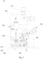
- the fixing mechanism 200 passes by a first position and a second position in the process of reciprocating in the first direction. As shown in Fig. 3 , when the material tape unreeled by the second unreeling assembly 120 is used as the working material tape 21, the fixing mechanism 200 is located at the first position, the second fixing assembly 220 is aligned with the first positioning assembly 320, and the working material tape 21 unreeled by the second unreeling assembly 120 sequentially passes through the second fixing assembly 220, the first cutting assembly 310 and the first positioning assembly 320 until it is conveyed downstream to a cutting station to be cut into pieces.
- the material tape on the first unreeling assembly 110 is the spare material tape 22.
- the second fixing assembly 220 and the first positioning assembly 320 will fix the working material tape 21 at the same time, and the first cutting assembly 310 will cut off the fixed working material tape 21, thus obtaining the working material tape 21 fixed on the first positioning assembly 320.
- the unreeling mechanism 100 and the fixing mechanism 200 are moved to the second position in the first direction (the top shown in Fig. 3 ), so that the first fixing assembly 210 is aligned with the first positioning assembly 320.
- the spare material tape 22 unreeled by the first unreeling assembly 110 is aligned with the working material tape 21 fixed by the first positioning assembly 320.
- An adhesive attaching mechanism 400 attaches adhesive pieces 30 (as shown in Fig. 10 ) to at least a side (usually both sides) of the aligned spare material tape 22 and working material tape 21, and part of the adhesive piece 30 is bonded to a starting end of the spare material tape 22 and the other part is bonded to a cut end of the working material tape 21, so that the spare material tape 22 unreeled by the first unreeling assembly 110 can be connected with the original working material tape 21 to form a new working material tape 21.
- the first fixing assembly 210 and the first positioning assembly 320 respectively release the fixed material tapes, and the first unreeling assembly 110 can unreel and output the working material tape 21 downstream.
- the first unreeling assembly 110 unreels and outputs the working material tape 21
- a new reel can be loaded onto the second unreeling assembly 120 to serve as the spare material tape 22.
- the tape connecting mechanism 300 further comprises a first driver 330 which is connected with the first cutting assembly 310 in a driving mode and able to drive the first cutting assembly 310 to move close to or away from the material tape between the first positioning assembly 320 and the fixing mechanism 200.
- the first driver 330 drives the first cutting assembly 310 to move in the same direction as the fixing mechanism 200, which is the first direction. After the working material tape 21 fixed by the fixing mechanism 200 and the first positioning assembly 320 is cut off, the first cutting assembly 310 can be driven by the first driver 330 to move away from the working material tape 21, thus exposing the cut end of the working material tape 21 and avoiding the adhesive attaching track of the adhesive attaching mechanism 400, so as to prevent the situation that the adhesive attaching mechanism 400 cannot attach the adhesive pieces 30 to the spare material tape 22 and the working material tape 21 smoothly due to the blocking of the first cutting assembly 310.
- the material tapes between the first positioning assembly 320 and the fixing mechanism 200 are the working material tape 21, and in the coil replacing process, the material tapes between the first positioning assembly 320 and the fixing mechanism 200 include both the working material tape 21 and the spare material tape 22.
- the first fixing assembly 210 and the first positioning assembly 320 fix the current working material tape 21 at the same time, and then the fixed working material tape 21 is cut off by the first cutting assembly 310. Then, the unreeling mechanism 100 and the fixing mechanism 200 are moved to the first position in the first direction (the bottom shown in Fig. 3 ) relative to the first positioning assembly 320, so that the second fixing assembly 220 is aligned with the first positioning assembly 320. At this point, the spare material tape 22 unreeled by the second unreeling assembly 120 is aligned with the working material tape 21 fixed by the first positioning assembly 320.
- the adhesive attaching mechanism 400 attaches the adhesive pieces 30 to at least a side of the aligned spare material tape 22 and working material tape 21, so that the spare material tape 22 unreeled by the second unreeling assembly 120 can be connected with the original working material tape 21 to form a new working material tape 21. Then, the second fixing assembly 220 and the first positioning assembly 320 respectively release the fixed material tapes, and the second unreeling assembly 120 can unreel and output the working material tape 21 downstream. When the second unreeling assembly 120 unreels and outputs the working material tape 21, a new reel can be loaded onto the first unreeling assembly 110 as the spare material tape 22.
- the first unreeling assembly 110 and the second unreeling assembly 120 alternately unreel the working material tape 21, and automatic coil replacing is realized after the working material tape 21 is completely unreeled.
- the first positioning assembly 320 keeps the original working material tape 21 fixed
- the fixing mechanism 200 keeps the spare material tape 22 fixed, thus ensuring reliable alignment between the working material tape 21 and the spare material tape 22.
- the fixing mechanism 200 is fixedly connected with the unreeling mechanism 100, so that the first unreeling assembly 110 and the second unreeling assembly 120 can move in the first direction synchronously with the fixing mechanism 200. In this way, the relative positions between the first unreeling assembly 110 and the second unreeling assembly 120 and the first fixing assembly 210 and the second fixing assembly 220 can remain unchanged. In the coil replacing process, when the unreeling mechanism 100 and the fixing mechanism 200 reciprocate in the first direction, synchronism is better.
- the coil replacing device 10 further comprises a base plate 600 and a transmission mechanism 700.
- the unreeling mechanism 100 further comprises a moving plate 130 slidably mounted on the base plate 600 in the first direction, and the first unreeling assembly 110, the second unreeling assembly 120 and the fixing mechanism 200 are all mounted on the moving plate 130.
- the transmission mechanism 700 may be an air cylinder, an electric cylinder or a motor (used in conjunction with a screw pair), etc.
- the transmission mechanism 700 can drive the moving plate 130 to slide in the first direction, so as to drive the fixing mechanism 200 to move between the first position and the second position. It can be seen that when the transmission mechanism 700 drives the fixing mechanism 200 to move in the first direction, the first unreeling assembly 110 and the second unreeling assembly 120 will also move synchronously with the moving plate 130 in the first direction.
- the base plate 600 can be fixedly connected with a large plate of other equipment, such as a winder, and the tape connecting mechanism 300 may also be mounted on the base plate 600.
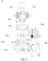
- the unreeling mechanism 100 further comprises a vertical plate 140 which is mounted on the moving plate 130 and extends in a direction perpendicular to a surface of the base plate 600, and the first unreeling assembly 110 and the second unreeling assembly 120 are both arranged on the vertical plate 140. It can be seen that the unreeling mechanism 100 can reasonably utilize the space above the base plate 600, thus making the structure of the coil replacing device 100 more compact.
- the unreeling mechanism 100 is arranged at an end of the base plate 600 in the second direction, which is perpendicular to the first direction, that is, the left-right direction shown in Fig. 1 .
- the tape connecting mechanism 300 and the unreeling mechanism 100 are spaced apart in the second direction, and the adhesive attaching mechanism 400 and the tape connecting mechanism 300 are spaced apart in the first direction. Therefore, the space above the base plate 600 can be fully utilized, thus making the structure of the coil replacing device 100 more compact.
- the tape connecting mechanism 300 further comprises a second positioning assembly 340 and a second cutting assembly 350.
- the second positioning assembly 340 is located on a side of the first positioning assembly 320 in the first direction and is spaced from the first positioning assembly 320, and the second cutting assembly 350 is located upstream (the left side in Fig. 2 ) of the second positioning assembly 340.
- the second fixing assembly 220 is aligned with the first positioning assembly 320, and the first fixing assembly 210 will also be aligned with the second positioning assembly 340.
- the spare material tape 22 unreeled by the first unreeling assembly 110 passes through the second cutting assembly 350 and the second positioning assembly 340 in sequence, and the second cutting assembly 350 can cut off the spare material tape 22 fixed by the first fixing assembly 210 and the second positioning assembly 340.
- the tape connecting mechanism 300 further comprises a third positioning assembly 360 and a third cutting assembly 370, the third positioning assembly 360 is located on a side, facing away from the second positioning assembly 340, of the first positioning assembly 320 and is spaced from the first positioning assembly 320, and the third cutting assembly 370 is located upstream of the third positioning assembly 360. That is, the third positioning assembly 360 and the second positioning assembly 340 are located on two sides of the first positioning assembly 320 respectively in the first direction, i.e., the upper and lower sides as shown in Fig. 3 .
- the first fixing assembly 210 When the fixing mechanism 200 passes by the second position, the first fixing assembly 210 will be aligned with the first positioning assembly 320, and the second fixing assembly 220 will also be aligned with the third positioning assembly 360.
- the spare material tape 22 unreeled by the second unreeling assembly 120 passes through the third cutting assembly 370 and the third positioning assembly 360 in sequence, and the third cutting assembly 370 can cut off the spare material tape 22 fixed by the second fixing assembly 220 and the third positioning assembly 360.
- the spare material tape 22 unreeled by the second unreeling assembly 120 will also be cut off, thus forming the spare material tape 22 fixed to the second fixing assembly 220.
- the length of the spare material tape 22 stretching out the second fixing assembly 220 can be consistent with the length of the spare material tape 22 stretching out the first fixing assembly 210.
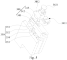
- the second cutting assembly 350 comprises an upper cutter 351, a lower cutter 352 and a cutting driver 353.
- the spare material tape 22 unreeled by the first unreeling assembly 110 is supported by the lower cutter 352 when passing through the second cutting assembly 350, and the lower cutter 352 is located on a side, facing away from the second positioning assembly 340, of the upper cutter 351.
- the lower cutter 352 is located on the side, facing away from the second positioning assembly 340, of the upper cutter 351, that is, the lower cutter 352 is located upstream of the upper cutter 351 (the right side in Fig. 3 ), when the spare material tape 22 is cut off, a supporting surface (upper surface) of the lower cutter 352 can support the starting end of the spare material tape 22, thereby preventing the starting end of the spare material tape 22 from being tilted.
- the second positioning assembly 340 comprises a supporting plate 341, a pressing rod 342 and an elastic member 343, and the pressing rod 342 is able to press the spare material tape 22 on a supporting surface of the supporting plate 341 under an action of the elastic member 343.
- the lower cutter 352 is fixedly connected with the supporting plate 341, and the supporting surface of the lower cutter 352 is flush with the supporting surface of the supporting plate 341.
- the spare material tape 22 unreeled by the first unreeling assembly 110 can be manually pulled to the second positioning assembly 340 and fixed, so that both the first fixing assembly 210 and the second positioning assembly 340 can fix the spare material tape 22.
- the supporting plate 341 can support the spare material tape 22.
- the pressing rod 342 can be lifted manually to keep the pressing rod 342 away from the supporting plate 341. After the spare material tape 22 passes under the pressing rod 342, the pressing rod 342 can be released to abut against the supporting surface of the supporting plate 341 under the action of the elastic member 343, so as to press the spare material tape 22.
- the structure of the tape connecting mechanism 300 can be simplified to some extent, thus making the structure of the coil replacing device 10 more compact.
- both the supporting surface of the supporting plate 341 and the supporting surface of the lower cutter 352 can support the spare material tape 22 and keep it still, so that the starting end of the spare material tape 22 can be prevented from being tilted after cutting off.
- a guide groove 3411 for the spare material tape 22 to pass through is formed in the surface of the supporting plate 341.
- the guide groove 3411 can guide and limit the spare material tape 22, thus facilitating accurate pulling of the spare material tape 22.
- the supporting plate 341 is provided with two guide blocks (not shown) which are arranged opposite to each other, thus forming the guide groove 3411.
- the guide groove 3411 can also be integrally formed with the supporting plate 341.
- the adhesive attaching driver 410 can drive the two suction plates 420 to be unfolded.
- the suction surfaces of the two suction plates 420 face upwards and are roughly horizontal, so that the adhesive pieces 30 stored in advance or prepared in real time by other mechanisms can be successfully received and sucked by the suction surfaces of the suction plates 420.
- the two suction plates 420 remain unfolded, and the swing assembly 430 drives the adhesive attaching driver 410 to swing to the adhesive attaching position.
- the two suction plates 420 are located on the upper side and the lower side of the aligned spare material tape 22 and working material tape 21 respectively.
- the adhesive attaching driver 410 needs to swing by about 90 degrees, so the suction surfaces of the two suction plates 420 will be switched from horizontal to roughly vertical, and one suction plate 420 is located above the aligned spare material tape 22 and working material tape 21, while the other suction plate 420 is located below the aligned spare material tape 22 and working material tape 21.
- the adhesive attaching driver 410 drives the two suction plates 420 to be folded, and the suction surfaces of the two suction plates 420 move close to each other until the cut end of the working material tape 21 and the starting end of the spare material tape 22 are clamped between the two suction plates 420.
- the adhesive pieces 30 on the suction surfaces of the suction plates 420 can be bonded with the starting end of the spare material tape 22 and the cut end of the working material tape 21, thereby connecting the spare material tape 22 with the working material tape 21.
- the two suction plates 420 will be unfolded again under the driving of the adhesive attaching driver 410, and will be driven by the swing assembly 430 to return to the adhesive preparation position to prepare for the next round of adhesive attachment.
- the adhesive attaching mechanism 400 can quickly realize automatic adhesive attachment, thus further improving the coil replacing efficiency of the coil replacing device 10.
- the adhesive attaching mechanism 400 when switching between the adhesive preparation position and the adhesive attaching position, the adhesive attaching mechanism 400 only needs to swing around the rotating shaft, and there is no need to arrange linear driving assemblies in multiple directions, so that the structure of the adhesive attaching mechanism 400 can be simplified.
- the swing assembly 430 comprises a support 431, a swing base 432 and a swing driver 433, the swing base 432 is rotatably mounted on the support 431, the adhesive attaching driver 410 is fixedly mounted on the swing base 432, and the swing driver 433 is able to drive the swing base 432 to rotate, so that the swing base 432 drives the adhesive attaching driver 410 to swing between the adhesive preparation position and the adhesive attaching position.
- a U-shaped mounting part (not shown) is formed on the support 431, and the swing base 432 can be rotatably mounted in the U-shaped mounting part of the support 431 through a pin shaft (not shown), thus ensuring stability in the rotating process.
- the swing base 432 can provide a large mounting area for the adhesive attaching driver 410.
- the swing assembly 430 further comprises a connecting rod 434, an end of the connecting rod 434 is fixedly connected with the pin shaft, and another end of the connecting rod 434 is hinged to a moving end of the swing driver 433.
- the moving end of the swing driver 433 can be controlled to stretch out and draw back, and drive the pin shaft to rotate through the connecting rod 434, thereby driving the swing base 432 to rotate.
- the swing driver 433 may be an air cylinder, a fixed end of which can be hinged to a second slide plate 443 of a transfer assembly 440 (see Figs. 6 and 7 ).
- the coil replacing device 10 further comprises an adhesive preparation mechanism 500 which is able to cut unreeled adhesive tape into adhesive pieces 30 and transport the adhesive pieces 30 to the surfaces of the suction plates 420 located at the adhesive preparation position.
- the adhesive preparation mechanism 500 can also be mounted on the base plate 600.
- the adhesive preparation mechanism 500 can prepare the adhesive pieces 30 in real time by using adhesive tape, so that the coil replacing device 10 can realize integrated operation of adhesive preparation and attachment, and manual operation can be further reduced.
- the adhesive pieces 30 prepared by the adhesive preparation mechanism 500 can be directly transferred to the surfaces of the suction plates 420 without the need for storage, so the problem that the surfaces of the adhesive pieces 30 are contaminated during storage can be avoided.
- the adhesive preparation mechanism 500 comprises an adhesive tape unreeling assembly 510, a pulling assembly 520 and a cutting assembly 530.
- the adhesive pieces 30 obtained from each cutting by the cutting assembly 530 can be directly received by the suction plates 420, thus speeding up the loading of the adhesive pieces 30 and avoiding the contamination of the adhesive pieces 30.
- the adhesive preparation mechanism 500 also comprises a supporting base 540 playing a supporting role, and the adhesive tape unreeling assembly 510, the pulling assembly 520 and the cutting assembly 530 are all mounted on the supporting base 540.
- the supporting base 540 can vertically extend along a surface of the base 600, so that the space above the base 600 can be reasonably utilized, and the structure of the coil replacing device 10 is more compact.
- the adhesive preparation mechanism 500 further comprises a depressing assembly 560 which is able to fix the adhesive tape between the pulling assembly 520 and the adhesive tape unreeling assembly 510 and drive the fixed adhesive tape to move toward the suction plates 420 (the bottom in Fig. 6 ) until the adhesive tape above the suction plates 420 is sucked by the suction plates 420.
- the adhesive pieces 30 are sucked by the suction plates 420 before being cut off from the adhesive tape, so the adhesive pieces 30 obtained after the cutting assembly 530 cuts off the adhesive tape will be directly fixed on the suction surfaces of the suction plates 420, thus omitting the process of transferring the sheet-like adhesive pieces 30 from an output end of the adhesive preparation mechanism 500 to the suction plates 420, and avoiding the contamination, warping or deflection of the adhesive pieces 30 during the transfer process.
- a connecting plate 550 is slidably connected with the supporting base 540 in a vertical direction, and the cutting assembly 530 and the depressing assembly 560 are both mounted on the connecting plate 550.
- the depressing assembly 560 comprises a pressing cylinder 561, a first clamping jaw 562 and a second clamping jaw 563, the first clamping jaw 562 is fixed to a moving end of the pressing cylinder 561, and the second clamping jaw 563 is arranged below the first clamping jaw 562 and fixedly connected with the connecting plate 550.
- a second connecting base 570 is slidably connected with a side, facing away from the connecting plate 550, of the supporting base 540 in the vertical direction, and the second connecting base 570 is fixedly connected with the connecting plate 550 through a connecting block (not shown).
- the supporting base 540 is provided with a first cylinder 581, and a moving end of the first cylinder 581 is fixedly connected with the second connecting base 570.
- a moving base 590 is slidably connected with the second connecting base 570 in the horizontal direction, the second connecting base 570 is provided with a second cylinder 582, and a moving end of the second cylinder 582 is fixedly connected with the moving base 590.
- the pulling assembly 520 comprises a pulling cylinder 521, and the pulling cylinder 521 is fixedly arranged on the moving base 590. Two moving ends of the pulling cylinder 521 are fixedly connected with a third clamping jaw 522 and a fourth clamping jaw 523 respectively. When pulling the adhesive tape, the third clamping jaw 522 and the fourth clamping jaw 523 clamp the adhesive tape and are driven by the second cylinder 582 to move horizontally with the moving base 590 to pull a preset length of adhesive tape.
- the first clamping jaw 562 is driven by the pressing cylinder 561 to cooperate with the second clamping jaw 563 to clamp the adhesive tape, and the first cylinder 581 drives the connecting plate 550 to descend, thus driving the depressing assembly 560 to drive the clamped adhesive tape downward until the adhesive tape pulled by the pulling assembly 520 is sucked by the suction surfaces of the suction plates 420.
- the cutting assembly 530 cuts off the adhesive tape to obtain the adhesive pieces 30 sucked by the suction plates 420.
- the adhesive attaching mechanism 400 further comprises a transfer assembly 440 which can drive the adhesive attaching driver 410 to move in the first direction when the adhesive attaching driver 410 is located at the adhesive preparation position, so that the two suction plates 420 sequentially pass through a position for receiving the adhesive pieces 30 output by the adhesive preparation mechanism 500.
- the position for receiving the adhesive pieces 30 output by the adhesive preparation mechanism 500 refers to the direction of the output end of the adhesive preparation mechanism 500.
- the transfer assembly 440 drives the adhesive attaching driver 410 to move in the first direction for a certain distance (generally, the distance between the two suction plates 420), so that the other suction plate 420 can also enter the position for receiving the adhesive pieces 30 output by the adhesive preparation mechanism 500, and the other suction plate 420 can receive the adhesive pieces 30 output by the adhesive preparation mechanism 500.
- a certain distance generally, the distance between the two suction plates 420
- the adhesive preparation position includes two positions, namely a first adhesive preparation sub-position and a second adhesive preparation sub-position.
- the adhesive attaching driver 410 entering the adhesive preparation position is located at the first adhesive preparation sub-position, so the upper suction plate 420 first receives the adhesive pieces 30 output by the adhesive preparation mechanism 500; and then, the transfer assembly 440 can drive the adhesive attaching driver 410 to move upward for a certain distance, so that the adhesive attaching driver 410 can move to the second adhesive preparation sub-position, so that the lower suction plate 420 can also receive the adhesive pieces 30 output by the adhesive preparation mechanism 500.
- the transfer assembly 440 may be omitted, and the output end of the adhesive preparation mechanism 500 may be moved in the first direction, so that the adhesive pieces obtained by cutting 30 are sequentially loaded to the suction surfaces of the two suction plates 420.
- the transfer assembly 440 can also drive the adhesive attaching driver 410 to move in the first direction, so that the two suction plates 420 can clamp the aligned spare material tape 22 and working material tape 21 when folded.
- the transfer assembly 440 can drive the adhesive attaching driver 410 to approach the material tape to be bonded, so as to ensure successful adhesive attachment by the adhesive attaching mechanism 400.
- the transfer assembly 440 comprises a first transfer structure (not shown) and a second transfer structure (not shown), and the first transfer structure can drive the adhesive attaching driver 410 to move in the first direction, so that the two suction plates 410 can sequentially pass through the position for receiving the adhesive pieces 30 output by the adhesive preparation mechanism 500.
- the second transfer structure can drive the adhesive attaching driver 410 to move in the first direction towards the material tape between the first positioning assembly 320 and the fixing mechanism 200, so that the two suction plates 420 can clamp the material tape between the first positioning assembly 320 and the fixing mechanism 200 when folded.
- the adhesive attaching driver 410 when at the adhesive preparation position, the adhesive attaching driver 410 can move in the first direction under the driving of the first transfer structure, and when at the adhesive attaching position, the adhesive attaching driver 410 can move in the first direction under the driving of the second transfer structure. Therefore, the adhesive attaching driver 410 will be driven by different transfer structures at different positions, so control is more convenient.
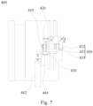
- the first transfer structure comprises a first slide plate 441 and a first transfer cylinder 442
- the second transfer structure comprises a second slide plate 443 and a second transfer cylinder 444.
- the first slide plate 441 can slide in the first direction under the driving of the first transfer cylinder 442.
- the first slide plate 441 can be slidably mounted on the base plate 600 in the first direction through a guide rail-slider pair, and the first transfer cylinder 442 is provided on the base plate 600.
- the second slide plate 443 is slidably mounted on the first slide plate 441 in the first direction, and the second transfer cylinder 444 is mounted on the first slide plate 441 and can drive the second slide plate 443 to slide in the first direction.
- the adhesive attaching driver 410 is mounted on the second slide plate 443.
- the support 431 of the adhesive attaching mechanism 400 is mounted on the second slide plate 443, so that the adhesive attaching driver 410 and the swing assembly 430 can move in the first direction along with the second slide plate 443 as a whole.
- the first transfer cylinder 442 can drive the first slide plate 441 to slide in the first direction, so as to drive the two suction plates 420 to sequentially pass through the position for receiving the adhesive pieces 30 output by the adhesive preparation mechanism 500.
- the second transfer cylinder 444 can drive the second slide plate 443 to slide in the first direction, so that the adhesive attaching driver 410 moves toward the material tape between the first positioning assembly 320 and the fixing mechanism 200 at the adhesive attaching position.
- the first transfer cylinder 442 and the second transfer cylinder 444 generally have different strokes.
- the stroke of the first transfer cylinder 442 is generally equal to the distance between the two suction plates 420.
- the reciprocating movement of the first transfer cylinder 442 can drive the two suction plates 420 to sequentially pass through the position for receiving the adhesive pieces output by the adhesive preparation mechanism 500. It can be seen that after the proper strokes of the first transfer cylinder 442 and the second transfer cylinder 444 are determined, the first transfer cylinder 442 and the second transfer cylinder 444 reciprocate according to a certain rule, so that adhesive preparation and attachment can be smoothly carried out, and control is more convenient.
- the transfer assembly 440 may also adopt other structures.
- the transfer assembly 440 adopts the structure of a motor and a screw pair matched with the motor, and the rotary motion of the motor is converted into the linear motion of the adhesive attaching driver 410 in the first direction.
- By controlling the number of rotation cycles of a motor spindle it is also possible to drive the two suction plates 420 to sequentially pass through the position for receiving the adhesive pieces output by the adhesive preparation mechanism 500, and make the adhesive attaching driver 410 move towards the material tape between the first positioning assembly 320 and the fixing mechanism 200 at the adhesive attaching position.
- the first unreeling assembly 110 and the second unreeling assembly 120 can output the working materials tape 21 and the spare materials tape 22 through unreeling.
- the first cutting assembly 310 cuts off the working material tape 21 fixed by both the fixing mechanism 200 and the first positioning assembly 320, and by moving the fixing mechanism 200 relative to the first positioning assembly 320 in the first direction, the spare material tape 22 unreeled by the second unreeling assembly 120 can be aligned with the working material tape 21 fixed by the first positioning assembly 320.
- the swing assembly 430 drives the adhesive attaching driver 410 to swing from the adhesive preparation position to the adhesive attaching position, and the adhesive attaching mechanism 400 drives the two suction plates 420 to be folded, so that the adhesive pieces 30 can be attached to the aligned spare material tape 22 and working material tape 21, thus connecting the spare material tape 22 with the working material tape 21 to form a new working material tape 21, and a new reel can be loaded onto the first unreeling assembly 110 to serve as a spare material tape 22.
- the coil replacing device 10 can realize automatic coil replacing, and coil replacing efficiency is high.
Landscapes
- Chemical & Material Sciences (AREA)
- Chemical Kinetics & Catalysis (AREA)
- Electrochemistry (AREA)
- General Chemical & Material Sciences (AREA)
- Adhesive Tape Dispensing Devices (AREA)
Claims (14)
- Rollenaustauschvorrichtung (10), umfassend:einen Abwickelmechanismus (100), umfassend eine erste Abwickelbaugruppe (110) und eine zweite Abwickelbaugruppe (120), wobei Materialbänder, die durch die erste Abwickelbaugruppe (110) und die zweite Abwickelbaugruppe (120) abgewickelt und ausgegeben werden, abwechselnd als ein Arbeitsmaterialband (21) und ein Ersatzmaterialband (22) verwendet werden;einen Fixierungsmechanismus (200), der dem Abwickelmechanismus (100) nachgeordnet ist und eine erste Fixierungsbaugruppe (210) und eine zweite Fixierungsbaugruppe (220) umfasst, wobei die erste Fixierungsbaugruppe (210) und die zweite Fixierungsbaugruppe (220) fähig sind, die jeweiligen Materialbänder, die durch die erste Abwickelbaugruppe (110) und die zweite Abwickelbaugruppe (120) abgewickelt und ausgegeben werden, zu fixieren;einen Bandverbindungsmechanismus (300), der dem Fixierungsmechanismus (200) nachgeordnet ist und eine erste Schneidbaugruppe (310) und eine erste Positionierungsbaugruppe (320) umfasst, wobei das Arbeitsmaterialband (21), das durch den Abwickelmechanismus (100) abgewickelt und ausgegeben wird, nacheinander den Fixierungsmechanismus (200) und den ersten Positionierungsbaugruppe (320) durchlaufen kann, wobei die erste Schneidbaugruppe (310) fähig ist, das Arbeitsmaterialband (21), das sowohl durch den Fixierungsmechanismus (200) als auch die erste Positionierungsbaugruppe (320) fixiert wird, abzuschneiden, und der Fixierungsmechanismus (200) fähig ist, sich in einer ersten Richtung hin- und herzubewegen, um dadurch das fixierte Ersatzmaterialband (22) an dem Arbeitsmaterialband (21) auszurichten, das durch die erste Positionierungsbaugruppe (320) fixiert ist; undeinen Klebstoffaufbringungsmechanismus (400), umfassend einen Klebstoffaufbringungsantrieb (410), Saugplatten (420) und eine Schwenkbaugruppe (430), wobei zwei Saugplatten (420) an einem antreibenden Ende des Klebstoffaufbringungsantriebs (410) angebracht sind und durch den Antrieb des Klebstoffaufbringungsantriebs (410) eingeklappt oder ausgeklappt werden können und die Schwenkbaugruppe (430) den Klebstoffaufbringungsantrieb (410) so antreiben kann, dass er zwischen einer Klebstoffvorbereitungsposition und einer Klebstoffaufbringungsposition schwingt;wobei, wenn sich der Klebstoffaufbringungsantrieb (410) in der Klebstoffvorbereitungsposition befindet, die zwei ausgeklappten Saugplatten (420) Klebestücke (30) aufnehmen und ansaugen können; und wenn der Klebstoffaufbringungsantrieb (410) in die Klebstoffaufbringungsposition schwingt, die zwei ausgeklappten Saugplatten (420) jeweils auf einer oberen Seite und einer unteren Seite des Ersatzmaterialbands (22) und des Arbeitsmaterialbands (21) angeordnet sind, die aneinander ausgerichtet sind, und wenn der Klebstoffaufbringungsantrieb (410) die zwei Saugplatten (420) einklappend antreibt, die durch die Saugplatten (420) angesaugten Klebestücke (30) an dem Ersatzmaterialband (22) und dem Arbeitsmaterialband (21), die aneinander ausgerichtet sind, angebracht werden;wobei die Rollenaustauschvorrichtung (10) dadurch gekennzeichnet ist, dass der Fixierungsmechanismus (200) eine erste Position und eine zweite Position durchläuft, während er sich in der ersten Richtung hin- und herbewegt,wobei der Bandverbindungsmechanismus (300) ferner eine zweite Positionierungsbaugruppe (340) und eine zweite Schneidbaugruppe (350) umfasst, die der zweiten Positionierungsbaugruppe (340) vorgeordnet ist, und die zweite Positionierungsbaugruppe (340) auf einer Seite der ersten Positionierungsbaugruppe (320) in der ersten Richtung angeordnet ist und von der ersten Positionierungsbaugruppe (320) beabstandet ist;wobei, wenn der Fixierungsmechanismus (200) die erste Position durchläuft, die erste Fixierungsbaugruppe (210) an der zweiten Positionierungsbaugruppe (340) ausgerichtet wird und die zweite Fixierungsbaugruppe (220) an der ersten Positionierungsbaugruppe (320) ausgerichtet wird, das Ersatzmaterialband (22), das durch die erste Abwickelbaugruppe (110) abgewickelt wird, nacheinander die zweite Schneidbaugruppe (350) und die zweite Positionierungsbaugruppe (340) durchläuft und die zweite Schneidbaugruppe (350) fähig ist, das Ersatzmaterialband (22), das sowohl durch die erste Fixierungsbaugruppe (210) als auch die zweite Positionierungsbaugruppe (340) fixiert wird, zu schneiden.
- Rollenaustauschvorrichtung (10) nach Anspruch 1, wobei der Fixierungsmechanismus (200) fest mit dem Abwickelmechanismus (100) verbunden ist, um die erste Abwickelbaugruppe (110) und die zweite Abwickelbaugruppe (120) in die Lage zu versetzen, sich synchron mit dem Fixierungsmechanismus (200) in der ersten Richtung zu bewegen.
- Rollenaustauschvorrichtung (10) nach Anspruch 2, ferner umfassend eine Grundplatte (600) und einen Getriebemechanismus (700), wobei der Abwickelmechanismus (100) ferner eine bewegliche Platte (130) umfasst, die in der ersten Richtung verschiebbar auf der Grundplatte (600) angebracht ist, wobei die erste Abwickelbaugruppe (110), die zweite Abwickelbaugruppe (120) und der Fixierungsmechanismus (200) an der beweglichen Platte (130) angebracht sind und der Getriebemechanismus (700) fähig ist, die bewegliche Platte (130) in der ersten Richtung zu verschieben, um den Fixierungsmechanismus (200) zur Hin- und Herbewegung in der ersten Richtung anzutreiben.
- Rollenaustauschvorrichtung (10) nach Anspruch 1, wobei die zweite Schneidbaugruppe (350) eine obere Schneide (351), eine untere Schneide (352) und einen Schneidenantrieb (353) umfasst, wobei das durch die erste Abwickelbaugruppe (110) abgewickelte Ersatzmaterialband (22) von der unteren Schneide (352) getragen wird, wenn es die zweite Schneidbaugruppe (350) durchläuft, und die untere Schneide (352) auf einer von der zweiten Positionierungsbaugruppe (340) abgewandten Seite der oberen Schneide (351) angeordnet ist.
- Rollenaustauschvorrichtung (10) nach Anspruch 4, wobei die zweite Positionierungsbaugruppe (340) eine Trägerplatte (341), eine Andrückstange (342) und ein elastisches Element (343) umfasst, wobei die Andrückstange (342) fähig ist, das Ersatzmaterialband (22) unter Einwirkung des elastischen Elements (343) an eine tragende Fläche der Trägerplatte (341) zu drücken, wobei die untere Schneide (352) fest mit der Trägerplatte (341) verbunden ist und eine tragende Fläche der unteren Schneide (352) mit der tragenden Fläche der Trägerplatte (341) bündig ist.
- Rollenaustauschvorrichtung (10) nach Anspruch 1, wobei der Bandverbindungsmechanismus (300) ferner eine dritte Positionierungsbaugruppe (360) und eine dritte Schneidbaugruppe (370) umfasst, die der dritten Positionierungsbaugruppe (360) vorgeordnet ist, wobei die dritte Positionierungsbaugruppe (360) auf einer von der zweiten Positionierungsbaugruppe (340) abgewandten Seite der ersten Positionierungsbaugruppe (320) angeordnet ist und von der ersten Positionierungsbaugruppe (320) beabstandet ist,
wobei, wenn der Fixierungsmechanismus (200) die zweite Position durchläuft, die erste Fixierungsbaugruppe (210) an der ersten Positionierungsbaugruppe (320) ausgerichtet wird, die zweite Fixierungsbaugruppe (220) an der dritten Positionierungsbaugruppe (360) ausgerichtet wird, das Ersatzmaterialband (22), das durch die zweite Abwickelbaugruppe (120) abgewickelt wird, nacheinander die dritte Schneidbaugruppe (370) und die dritte Positionierungsbaugruppe (360) durchläuft und die dritte Schneidbaugruppe (370) fähig ist, das Ersatzmaterialband (22), das sowohl durch die zweite Fixierungsbaugruppe (220) als auch die dritte Positionierungsbaugruppe (360) fixiert wird, zu schneiden. - Rollenaustauschvorrichtung (10) nach Anspruch 1, wobei der Bandverbindungsmechanismus (300) ferner einen ersten Antrieb (330) umfasst, der in einem Antriebsmodus mit der ersten Schneidbaugruppe (310) verbunden und fähig ist, die erste Schneidbaugruppe (310) so anzutreiben, dass sie sich dem Materialband zwischen der ersten Positionierungsbaugruppe (320) und dem Fixierungsmechanismus (200) annähert oder davon entfernt.
- Rollenaustauschvorrichtung nach Anspruch 1, ferner umfassend einen Klebstoffvorbereitungsmechanismus (500), der fähig ist, das abgewickelte Klebeband in Klebestücke (30) zu schneiden und die Klebestücke (30) zu Flächen der Saugplatten (420) zu transportieren, die in der Klebstoffvorbereitungsposition angeordnet sind.
- Rollenaustauschvorrichtung (10) nach Anspruch 8, wobei der Klebstoffvorbereitungsmechanismus (500) eine Klebebandabwickelbaugruppe (510), eine Zugbaugruppe (520) und eine Schneidbaugruppe (530) umfasst, wobei die Klebebandabwickelbaugruppe (510) zum Abwickeln des Klebebands dient, die Zugbaugruppe (520) zum Ziehen einer voreingestellten Länge an Klebeband über die Saugplatten (420) dient und die Schneidbaugruppe (530) zum Schneiden des Klebebands zwischen der Zugbaugruppe (520) und der Klebebandabwickelbaugruppe (510) dient, um die durch die Saugplatten (420) geladenen Klebestücke (30) zu erlangen;
wobei der Klebstoffvorbereitungsmechanismus (500) ferner eine Niederdrückbaugruppe (560) umfasst, die fähig ist, das Klebeband zwischen der Zugbaugruppe (520) und der Klebebandabwickelbaugruppe (510) zu fixieren und das fixierte Klebeband zu den Saugplatten (420) zu treiben, bis das Klebeband über den Saugplatten (420) durch die Saugplatten (420) angesaugt wird. - Rollenaustauschvorrichtung (10) nach Anspruch 8, wobei der Klebstoffaufbringungsmechanismus (400) ferner eine Transferbaugruppe (440) umfasst, die fähig ist, den Klebstoffaufbringungsantrieb (410) in der ersten Richtung anzutreiben, sodass die Saugplatten (420) nacheinander eine Position zum Aufnehmen der von dem Klebstoffvorbereitungsmechanismus (500) ausgegebenen Klebestücke (30) durchlaufen, wenn der Klebstoffaufbringungsantrieb (410) in der Klebstoffvorbereitungsposition angeordnet ist.
- Rollenaustauschvorrichtung (10) nach Anspruch 10, wobei, wenn der Klebstoffaufbringungsantrieb (410) in der Klebstoffaufbringungsposition angeordnet ist, die Transferbaugruppe (440) ferner fähig ist, den Klebstoffaufbringungsantrieb (410) in der ersten Richtung anzutreiben, sodass die zwei Saugplatten (420) das Ersatzmaterialband (22) und das Arbeitsmaterialband (21), die zwischen der ersten Positionierungsbaugruppe (320) und dem Fixierungsmechanismus (200) ausgerichtet sind, einklemmen können, wenn die zwei Saugplatten (420) eingeklappt sind.
- Rollenaustauschvorrichtung (10) nach Anspruch 11, wobei die Transferbaugruppe (440) eine erste Transferstruktur und eine zweite Transferstruktur umfasst, wobei die erste Transferstruktur fähig ist, den Klebstoffaufbringungsantrieb (410) in der ersten Richtung anzutreiben, sodass die zwei Saugplatten (420) nacheinander die Position zum Aufnehmen der von dem Klebstoffvorbereitungsmechanismus (500) ausgegebenen Klebestücke (30) durchlaufen, und die zweite Transferstruktur fähig ist, den Klebstoffaufbringungsantrieb (410) in der ersten Richtung anzutreiben, sodass die zwei Saugplatten (420) das Ersatzmaterialband (22) und das Arbeitsmaterialband (21), die zwischen der ersten Positionierungsbaugruppe (320) und dem Fixierungsmechanismus (200) ausgerichtet sind, einklemmen können, wenn die zwei Saugplatten (420) eingeklappt sind.
- Rollenaustauschvorrichtung (10) nach Anspruch 12, wobei die erste Transferstruktur eine erste Gleitplatte (441) und einen ersten Transferzylinder (442) umfasst und die zweite Transferstruktur eine zweite Gleitplatte (443) und einen zweiten Transferzylinder (444) umfasst;
wobei die zweite Gleitplatte (443) in der ersten Richtung verschiebbar an der ersten Gleitplatte (441) angebracht ist, der Klebstoffaufbringungsantrieb (410) an der zweiten Gleitplatte (443) angebracht ist, die erste Gleitplatte (441) fähig ist, den ersten Transferzylinder (442) in der ersten Richtung zu verschieben, und der zweite Transferzylinder (444) an der ersten Gleitplatte (441) angebracht und fähig ist, die zweite Gleitplatte (443) in der ersten Richtung zu verschieben. - Rollenaustauschvorrichtung (10) nach Anspruch 1, wobei die Schwenkbaugruppe (430) einen Träger (431), eine Schwenkbasis (432) und einen Schwenkantrieb (433) umfasst, wobei die Schwenkbasis (432) drehbar an dem Träger (431) angebracht ist, der Klebstoffaufbringungsantrieb (410) fest an der Schwenkbasis (432) angebracht ist und der Schwenkantrieb (433) fähig ist, die Schwekbasis (432) drehend anzutreiben, sodass die Schwenkbasis (432) den Klebstoffaufbringungsantrieb (410) zwischen der Klebstoffvorbereitungsposition und der Klebstoffaufbringungsposition schwingend antreibt.
Applications Claiming Priority (2)
| Application Number | Priority Date | Filing Date | Title |
|---|---|---|---|
| CN202211080328.XA CN115548596A (zh) | 2022-09-05 | 2022-09-05 | 换卷装置 |
| PCT/CN2022/129207 WO2024050948A1 (zh) | 2022-09-05 | 2022-11-02 | 换卷装置 |
Publications (4)
| Publication Number | Publication Date |
|---|---|
| EP4362209A1 EP4362209A1 (de) | 2024-05-01 |
| EP4362209A4 EP4362209A4 (de) | 2024-06-12 |
| EP4362209C0 EP4362209C0 (de) | 2025-04-30 |
| EP4362209B1 true EP4362209B1 (de) | 2025-04-30 |
Family
ID=90061240
Family Applications (1)
| Application Number | Title | Priority Date | Filing Date |
|---|---|---|---|
| EP22834825.6A Active EP4362209B1 (de) | 2022-09-05 | 2022-11-02 | Rollenwechselvorrichtung |
Country Status (2)
| Country | Link |
|---|---|
| US (1) | US12325603B2 (de) |
| EP (1) | EP4362209B1 (de) |
Families Citing this family (3)
| Publication number | Priority date | Publication date | Assignee | Title |
|---|---|---|---|---|
| WO2021129077A1 (zh) * | 2019-12-24 | 2021-07-01 | 无锡先导智能装备股份有限公司 | 自动换卷装置及卷绕设备 |
| CN112828603A (zh) * | 2021-02-09 | 2021-05-25 | 无锡先导智能装备股份有限公司 | 换卷装置及极耳焊接设备 |
| CN118919181B (zh) * | 2024-10-12 | 2025-03-21 | 河南普天电线电缆有限公司 | 一种新能源汽车电缆生产用押出机 |
Family Cites Families (10)
| Publication number | Priority date | Publication date | Assignee | Title |
|---|---|---|---|---|
| DE4016578A1 (de) * | 1990-05-23 | 1991-11-28 | Winkler Duennebier Kg Masch | Vorrichtung zum verbinden von materialbahnen |
| JP3653337B2 (ja) | 1996-05-20 | 2005-05-25 | 信越ポリマー株式会社 | テープ巻取装置 |
| DE102005033486A1 (de) * | 2005-07-19 | 2007-01-25 | Krones Ag | Vorrichtung und Verfahren zum Spleißen von Etikettenbändern |
| US8002924B2 (en) * | 2009-01-27 | 2011-08-23 | Tamarack Products, Inc. | Apparatus for splicing webs |
| WO2016002532A1 (ja) * | 2014-06-30 | 2016-01-07 | 株式会社瑞光 | シート繰出システム及びこれを用いたシート繰出方法 |
| CN110600812B (zh) | 2019-09-30 | 2024-04-26 | 广东泽源智能装备有限公司 | 一种极片自动换卷机构 |
| CN112186272B (zh) * | 2020-10-19 | 2024-06-04 | 无锡先导智能装备股份有限公司 | 极耳换卷装置及卷绕设备 |
| CN112828603A (zh) * | 2021-02-09 | 2021-05-25 | 无锡先导智能装备股份有限公司 | 换卷装置及极耳焊接设备 |
| CN114314109B (zh) | 2021-12-31 | 2024-06-04 | 无锡先导智能装备股份有限公司 | 一种换卷设备 |
| CN115548596A (zh) | 2022-09-05 | 2022-12-30 | 无锡先导智能装备股份有限公司 | 换卷装置 |
-
2022
- 2022-11-02 EP EP22834825.6A patent/EP4362209B1/de active Active
-
2023
- 2023-01-10 US US18/152,269 patent/US12325603B2/en active Active
Also Published As
| Publication number | Publication date |
|---|---|
| EP4362209C0 (de) | 2025-04-30 |
| US20240076156A1 (en) | 2024-03-07 |
| US12325603B2 (en) | 2025-06-10 |
| EP4362209A4 (de) | 2024-06-12 |
| EP4362209A1 (de) | 2024-05-01 |
Similar Documents
| Publication | Publication Date | Title |
|---|---|---|
| EP4362209B1 (de) | Rollenwechselvorrichtung | |
| EP4117077A1 (de) | Laschenrollenwechselvorrichtung und wickelvorrichtung | |
| US12420367B2 (en) | Roll replacing device and tab welding apparatus | |
| CN115548596A (zh) | 换卷装置 | |
| CN112456199B (zh) | 换卷装置及卷绕设备 | |
| EP4112517A1 (de) | Rollenwechselvorrichtung und klebebandklebevorrichtung | |
| CN108701869B (zh) | 一种用于电芯卷绕的自动换带装置以及电芯卷绕设备 | |
| CN219017738U (zh) | 叠片装置 | |
| CN214114355U (zh) | 换卷装置及卷绕设备 | |
| CN110759148A (zh) | 自动接带装置 | |
| CN117438667A (zh) | 一种卷绕设备 | |
| CN218602694U (zh) | 换卷装置 | |
| CN213401287U (zh) | 极耳换卷装置及卷绕设备 | |
| CN115632168A (zh) | 叠片装置 | |
| CN117712454B (zh) | 叠片装置及电池生产线 | |
| CN211110195U (zh) | 料带牵引机构及料带卷绕装置 | |
| CN219859788U (zh) | 贴胶装置 | |
| CN120300248A (zh) | 卷绕设备及电池制造设备 | |
| EP4361072A1 (de) | Spulenaustauschvorrichtung | |
| CN216996910U (zh) | 接带装置及换卷设备 | |
| US12264025B2 (en) | Roll replacing apparatus and winding device | |
| CN211056315U (zh) | 自动接带装置 | |
| CN210576292U (zh) | 一种卷绕制片一体机 | |
| CN220519710U (zh) | 入料装置及卷绕设备 | |
| CN217417538U (zh) | 自动换卷装置 |
Legal Events
| Date | Code | Title | Description |
|---|---|---|---|
| STAA | Information on the status of an ep patent application or granted ep patent |
Free format text: STATUS: UNKNOWN |
|
| STAA | Information on the status of an ep patent application or granted ep patent |
Free format text: STATUS: THE INTERNATIONAL PUBLICATION HAS BEEN MADE |
|
| PUAI | Public reference made under article 153(3) epc to a published international application that has entered the european phase |
Free format text: ORIGINAL CODE: 0009012 |
|
| STAA | Information on the status of an ep patent application or granted ep patent |
Free format text: STATUS: REQUEST FOR EXAMINATION WAS MADE |
|
| 17P | Request for examination filed |
Effective date: 20230110 |
|
| AK | Designated contracting states |
Kind code of ref document: A1 Designated state(s): AL AT BE BG CH CY CZ DE DK EE ES FI FR GB GR HR HU IE IS IT LI LT LU LV MC ME MK MT NL NO PL PT RO RS SE SI SK SM TR |
|
| A4 | Supplementary search report drawn up and despatched |
Effective date: 20240513 |
|
| RIC1 | Information provided on ipc code assigned before grant |
Ipc: B65H 19/18 20060101ALI20240506BHEP Ipc: H01M 50/536 20210101AFI20240506BHEP |
|
| GRAP | Despatch of communication of intention to grant a patent |
Free format text: ORIGINAL CODE: EPIDOSNIGR1 |
|
| STAA | Information on the status of an ep patent application or granted ep patent |
Free format text: STATUS: GRANT OF PATENT IS INTENDED |
|
| RIC1 | Information provided on ipc code assigned before grant |
Ipc: B65H 19/18 20060101ALI20250205BHEP Ipc: H01M 50/536 20210101AFI20250205BHEP |
|
| GRAS | Grant fee paid |
Free format text: ORIGINAL CODE: EPIDOSNIGR3 |
|
| GRAA | (expected) grant |
Free format text: ORIGINAL CODE: 0009210 |
|
| STAA | Information on the status of an ep patent application or granted ep patent |
Free format text: STATUS: THE PATENT HAS BEEN GRANTED |
|
| DAV | Request for validation of the european patent (deleted) | ||
| DAX | Request for extension of the european patent (deleted) | ||
| INTG | Intention to grant announced |
Effective date: 20250227 |
|
| AK | Designated contracting states |
Kind code of ref document: B1 Designated state(s): AL AT BE BG CH CY CZ DE DK EE ES FI FR GB GR HR HU IE IS IT LI LT LU LV MC ME MK MT NL NO PL PT RO RS SE SI SK SM TR |
|
| REG | Reference to a national code |
Ref country code: CH Ref legal event code: EP Ref country code: GB Ref legal event code: FG4D |
|
| REG | Reference to a national code |
Ref country code: IE Ref legal event code: FG4D |
|
| U01 | Request for unitary effect filed |
Effective date: 20250505 |
|
| U07 | Unitary effect registered |
Designated state(s): AT BE BG DE DK EE FI FR IT LT LU LV MT NL PT RO SE SI Effective date: 20250512 |
|
| REG | Reference to a national code |
Ref country code: HU Ref legal event code: AG4A Ref document number: E071161 Country of ref document: HU |
|
| PG25 | Lapsed in a contracting state [announced via postgrant information from national office to epo] |
Ref country code: ES Free format text: LAPSE BECAUSE OF FAILURE TO SUBMIT A TRANSLATION OF THE DESCRIPTION OR TO PAY THE FEE WITHIN THE PRESCRIBED TIME-LIMIT Effective date: 20250430 |
|
| PG25 | Lapsed in a contracting state [announced via postgrant information from national office to epo] |
Ref country code: NO Free format text: LAPSE BECAUSE OF FAILURE TO SUBMIT A TRANSLATION OF THE DESCRIPTION OR TO PAY THE FEE WITHIN THE PRESCRIBED TIME-LIMIT Effective date: 20250730 Ref country code: GR Free format text: LAPSE BECAUSE OF FAILURE TO SUBMIT A TRANSLATION OF THE DESCRIPTION OR TO PAY THE FEE WITHIN THE PRESCRIBED TIME-LIMIT Effective date: 20250731 |
|
| PG25 | Lapsed in a contracting state [announced via postgrant information from national office to epo] |
Ref country code: PL Free format text: LAPSE BECAUSE OF FAILURE TO SUBMIT A TRANSLATION OF THE DESCRIPTION OR TO PAY THE FEE WITHIN THE PRESCRIBED TIME-LIMIT Effective date: 20250430 |
|
| PG25 | Lapsed in a contracting state [announced via postgrant information from national office to epo] |
Ref country code: HR Free format text: LAPSE BECAUSE OF FAILURE TO SUBMIT A TRANSLATION OF THE DESCRIPTION OR TO PAY THE FEE WITHIN THE PRESCRIBED TIME-LIMIT Effective date: 20250430 |
|
| PG25 | Lapsed in a contracting state [announced via postgrant information from national office to epo] |
Ref country code: RS Free format text: LAPSE BECAUSE OF FAILURE TO SUBMIT A TRANSLATION OF THE DESCRIPTION OR TO PAY THE FEE WITHIN THE PRESCRIBED TIME-LIMIT Effective date: 20250731 |
|
| PG25 | Lapsed in a contracting state [announced via postgrant information from national office to epo] |
Ref country code: IS Free format text: LAPSE BECAUSE OF FAILURE TO SUBMIT A TRANSLATION OF THE DESCRIPTION OR TO PAY THE FEE WITHIN THE PRESCRIBED TIME-LIMIT Effective date: 20250830 |