EP4361003A1 - Tractor - Google Patents
Tractor Download PDFInfo
- Publication number
- EP4361003A1 EP4361003A1 EP22203955.4A EP22203955A EP4361003A1 EP 4361003 A1 EP4361003 A1 EP 4361003A1 EP 22203955 A EP22203955 A EP 22203955A EP 4361003 A1 EP4361003 A1 EP 4361003A1
- Authority
- EP
- European Patent Office
- Prior art keywords
- bonnet
- engine
- engine compartment
- exhaust
- cleaning apparatus
- Prior art date
- Legal status (The legal status is an assumption and is not a legal conclusion. Google has not performed a legal analysis and makes no representation as to the accuracy of the status listed.)
- Granted
Links
Images



Classifications
-
- B—PERFORMING OPERATIONS; TRANSPORTING
- B62—LAND VEHICLES FOR TRAVELLING OTHERWISE THAN ON RAILS
- B62D—MOTOR VEHICLES; TRAILERS
- B62D25/00—Superstructure or monocoque structure sub-units; Parts or details thereof not otherwise provided for
- B62D25/08—Front or rear portions
- B62D25/10—Bonnets or lids, e.g. for trucks, tractors, busses, work vehicles
-
- F—MECHANICAL ENGINEERING; LIGHTING; HEATING; WEAPONS; BLASTING
- F01—MACHINES OR ENGINES IN GENERAL; ENGINE PLANTS IN GENERAL; STEAM ENGINES
- F01N—GAS-FLOW SILENCERS OR EXHAUST APPARATUS FOR MACHINES OR ENGINES IN GENERAL; GAS-FLOW SILENCERS OR EXHAUST APPARATUS FOR INTERNAL-COMBUSTION ENGINES
- F01N2590/00—Exhaust or silencing apparatus adapted to particular use, e.g. for military applications, airplanes, submarines
- F01N2590/08—Exhaust or silencing apparatus adapted to particular use, e.g. for military applications, airplanes, submarines for heavy duty applications, e.g. trucks, buses, tractors, locomotives
-
- F—MECHANICAL ENGINEERING; LIGHTING; HEATING; WEAPONS; BLASTING
- F01—MACHINES OR ENGINES IN GENERAL; ENGINE PLANTS IN GENERAL; STEAM ENGINES
- F01N—GAS-FLOW SILENCERS OR EXHAUST APPARATUS FOR MACHINES OR ENGINES IN GENERAL; GAS-FLOW SILENCERS OR EXHAUST APPARATUS FOR INTERNAL-COMBUSTION ENGINES
- F01N2610/00—Adding substances to exhaust gases
- F01N2610/02—Adding substances to exhaust gases the substance being ammonia or urea
-
- F—MECHANICAL ENGINEERING; LIGHTING; HEATING; WEAPONS; BLASTING
- F01—MACHINES OR ENGINES IN GENERAL; ENGINE PLANTS IN GENERAL; STEAM ENGINES
- F01N—GAS-FLOW SILENCERS OR EXHAUST APPARATUS FOR MACHINES OR ENGINES IN GENERAL; GAS-FLOW SILENCERS OR EXHAUST APPARATUS FOR INTERNAL-COMBUSTION ENGINES
- F01N2900/00—Details of electrical control or of the monitoring of the exhaust gas treating apparatus
- F01N2900/06—Parameters used for exhaust control or diagnosing
Definitions
- the present invention relates to a tractor.
- tractors there are those that, as illustrated in patent literature 1 for example, are provided with an engine bonnet (bonnet) forming an engine compartment; a first exhaust-gas cleaning apparatus (first case) that, in the engine compartment, is provided above an engine (diesel engine) and subjects exhaust gas from the engine to a cleaning process; and a second exhaust-gas cleaning apparatus (second case) that is provided behind the engine and subjects the exhaust gas from the engine to a cleaning process.
- first case that, in the engine compartment, is provided above an engine (diesel engine) and subjects exhaust gas from the engine to a cleaning process
- second exhaust-gas cleaning apparatus second case
- the first exhaust-gas cleaning apparatus is housed above the engine, and the second exhaust-gas cleaning apparatus is housed behind the engine. This increases an up-down length and a front-back length of the engine compartment and increases a volume of the engine compartment such that a large engine bonnet is necessary.
- the present invention provides a tractor wherein it is easy to open and close an engine compartment despite an engine bonnet being large and wherein the engine bonnet is easy to produce.
- a tractor of the present invention is provided with: an engine bonnet forming an engine compartment; and a first exhaust-gas cleaning apparatus, which is provided above an engine in the engine compartment and subjects exhaust gas from the engine to a cleaning process, and second exhaust-gas cleaning apparatus, which is provided behind the engine and subjects the exhaust gas from the engine to a cleaning process; wherein the engine bonnet has a back bonnet, which covers a back engine compartment portion-wherein the second exhaust-gas cleaning apparatus is positioned-of the engine compartment and a front bonnet, which is configured as a separate body from the back bonnet in a state of covering a front engine compartment portion-positioned on a vehicle-body front side of the back engine compartment portion-of the engine compartment; and the front bonnet is supported in a state wherein it can swing open and closed.
- the engine compartment can be opened and closed by performing an operation of swinging only the front bonnet. This facilitates opening and closing the engine compartment.
- the engine bonnet can be produced by being divided into the front bonnet and the back bonnet. This facilitates production of the engine bonnet.
- the front bonnet is supported in a state of being able to swing open and closed, up and down, by using as a swinging fulcrum a pivot shaft core in a vehicle-body horizontal orientation provided to a back end portion of the front bonnet.
- an operation of raising a front end side of the front bonnet opens the front bonnet, and an operation of lowering the front end side of the front bonnet closes the front bonnet. This facilitates opening and closing the front bonnet.
- the front bonnet has a front top plate portion and front side plate portions that extend downward from left and right side portions of the front top plate portion
- the back bonnet has a back top plate portion that covers the back engine compartment portion from above and left and right back side plate portions that cover the back engine compartment portion from both horizontal sides
- a connecting bolt that connects a front portion of the back side plate portion to a support member
- the front bonnet is configured so in a closed state, a back portion of the front side plate portion is positioned on a horizontal outer side of the connecting bolt so as to cover the connecting bolt.
- the front bonnet becomes a cover covering the connecting bolt from the horizontal outer side.
- a simple cover structure that requires no special cover can prevent, for example, water leakage into the connecting bolt.
- the back bonnet has a back top plate portion that covers the back engine compartment portion from above and left and right back side plate portions that cover the back engine compartment portion from both horizontal sides, and the back top plate portion and the left and right back side plate portions are configured as separate bodies.
- the back bonnet can be produced by being divided into the back top plate portion and the left and right back side plate portions. This facilitates production of the back bonnet.
- the second exhaust-gas cleaning apparatus is configured to use a reducing agent to subject the exhaust gas from the engine to the cleaning process, and a reducing-agent tank and a reducing-agent pump, which supplies the reducing agent stored in the reducing-agent tank to the second exhaust-gas cleaning apparatus, are provided on a front side of the engine in the front engine compartment portion.
- a front-back length of the engine compartment becomes longer due to a space housing the reducing-agent tank and the reducing-agent pump, making an engine bonnet of a longer front-back length necessary.
- the engine bonnet can be produced by being divided into the front bonnet and the back bonnet. This facilitates production of the engine bonnet.
- the direction of arrow F illustrated in FIGS. 1 and 2 is defined as “vehicle-body front”
- the direction of arrow B is defined as “vehicle-body back”
- the direction of arrow U illustrated in FIG. 1 is defined as “vehicle-body up”
- the direction of arrow D is defined as “vehicle-body down”
- the direction of arrow L illustrated in FIG. 2 is defined as “vehicle-body left”
- the direction of arrow R is defined as “vehicle-body right”.
- the tractor is provided with a traveling vehicle body 3 supported by a pair of left and right front wheels 1, which can be steered and driven, and a pair of left and right back wheels 2, which can be driven.
- a vehicle body frame 4 of the traveling vehicle body 3 is constituted by an engine 5, a flywheel housing 6 connected to a back portion of the engine 5, a clutch housing 7 connected to a back portion of the flywheel housing 6, a transmission case 7a connected to a back portion of the clutch housing 7, and a front frame 8 connected to a lower portion of the engine 5.
- a motor unit 9 provided with the engine 5 is formed in a front portion of the traveling vehicle body 3.
- a linking mechanism 13 which connects a work apparatus such as a rotary tilling apparatus (not illustrated) in a manner enabling a raising and lowering operation of the work apparatus, and a power takeoff shaft 14, which takes power from the engine 5 and outputs this to the connected work apparatus, are provided in a back portion of the transmission case 7a.
- 20 illustrated in FIGS. 1 and 2 is a ROPS frame.
- the ROPS frame 20 is configured to be able to change attitudes between a storage attitude, which is a collapsed state of surrounding the motor unit 9, and a usage attitude, which is a raised state.
- the motor unit 9 is provided with an engine compartment 15.
- the engine compartment 15 is formed by an engine bonnet 16, which covers the engine compartment 15 from above, the front, and both horizontal sides; a partition member 17 that forms a partition between the engine compartment 15 and the driving unit 12; and the like.
- the engine 5 As illustrated in FIGS. 1 , 2 and 3 , the engine 5, a radiator 18 that cools the engine 5, a first exhaust-gas cleaning apparatus (DPF) 21 and second exhaust-gas cleaning apparatus (SCR) 22 that perform cleaning processes of exhaust gas exhausted by the engine 5, a reducing-agent tank 23, a reducing-agent pump 24, and a battery 25 are provided in the engine compartment 15.
- DPF first exhaust-gas cleaning apparatus
- SCR second exhaust-gas cleaning apparatus
- the radiator 18 is provided in front of the engine 5.
- a blowing action of a rotary fan 19 positioned between the radiator 18 and the engine 5 introduces cooling air from outside the engine compartment 15 to inside the engine compartment and supplies the cooling air to the radiator 18.
- the cooling air is supplied to the radiator 18 in a state of the cooling air passing through the radiator 18 from front to back.
- engine cooling water is cooled by heat exchange between the supplied cooling air and the engine cooling water.
- the engine 5 is cooled by the cooled engine cooling water being supplied to the engine 5.
- the engine 5 is a diesel engine. As illustrated in FIGS. 2 and 3 , the first exhaust-gas cleaning apparatus 21 is provided above the engine 5 in a state wherein a longitudinal direction of the first exhaust-gas cleaning apparatus adopts a vehicle-body horizontal orientation.
- a support member 26 is erected on the flywheel housing 6.
- a lower portion of the first exhaust-gas cleaning apparatus 21 is supported by a support arm 26a provided to the support member 26.
- the first exhaust-gas cleaning apparatus 21 is supported by the flywheel housing 6 of the vehicle body frame 4 via the support member 26.
- An exhaust-gas suctioning portion 21a which is provided to a part on one end side, in a vehicle-body horizontal width direction, of the first exhaust-gas cleaning apparatus 21, and an exhaust-gas exhausting portion 5a, which is provided to the engine 5, are connected.
- An exhaust-gas discharging portion 21b is provided to a part on another end side, in the vehicle-body horizontal width direction, of the first exhaust-gas cleaning apparatus 21.
- the exhaust gas exhausted by the engine 5 from the exhaust-gas exhausting portion 5a is suctioned by the exhaust-gas suctioning portion 21a into the apparatus, and diesel microparticles included in the suctioned exhaust gas are collected by a collection filter (not illustrated). This performs an exhaust-gas cleaning process of decreasing the diesel microparticles.
- the exhaust gas subjected to the cleaning process is discharged from the exhaust-gas discharging portion 21b.
- the second exhaust-gas cleaning apparatus 22 is provided behind the engine 5 in a state wherein a longitudinal direction of the second exhaust-gas cleaning apparatus adopts the vehicle-body horizontal orientation.
- a front portion of the second exhaust-gas cleaning apparatus 22 is supported by a strut portion 26b provided to the support member 26.
- the second exhaust-gas cleaning apparatus 22 is supported by the flywheel housing 6 of the vehicle body frame 4 via the support member 26.
- An exhaust-gas introduction portion 22a which is provided to a part on one end side, in the vehicle-body horizontal width direction, of the second exhaust-gas cleaning apparatus 22, and the exhaust-gas discharging portion 21b of the first exhaust-gas cleaning apparatus 21 are connected by a connecting pipe 27.
- An exhaust-gas discharging portion 22b is provided to a part on another end side, in the vehicle-body horizontal width direction, of the second exhaust-gas cleaning apparatus 22.
- the exhaust gas discharged by the first exhaust-gas cleaning apparatus 21 from the exhaust-gas discharging portion 21b is supplied by the connecting pipe 27 to the exhaust-gas introduction portion 22a and introduced by the exhaust-gas introduction portion 22a into the apparatus, and the introduced exhaust gas is subjected to the cleaning process by a reducing agent.
- aqueous urea as the reducing agent is injected into the introduced exhaust gas, hydrolyzing the exhaust gas. This performs an exhaust-gas cleaning process of decreasing nitrogen oxides included in the exhaust gas.
- the exhaust gas subjected to the cleaning process is exhausted from the exhaust-gas discharging portion 22b to a vehicle-body horizontal outer side.
- the reducing-agent tank 23, the reducing-agent pump 24, and the battery 25 are provided on a front side of the engine 5.
- the reducing-agent tank 23, the reducing-agent pump 24, and the battery 25 are lined up in the vehicle-body horizontal width direction.
- a support plate 28 is provided on an upper side of the front frame 8.
- the reducing-agent tank 23 is supported by the support plate 28 via a tank case 23a.
- the reducing-agent tank 23 has a pour tube 23b that extends forward and upward from an upper portion of the reducing-agent tank 23 and stores the aqueous urea as the reducing agent by the aqueous urea being poured in from the pour tube 23b.
- the reducing-agent pump 24 extracts the aqueous urea stored in the reducing-agent tank 23 from the reducing-agent tank 23 and supplies the extracted aqueous urea to the second exhaust-gas cleaning apparatus 22 via a hose (not illustrated) extending from the reducing-agent pump 24 to the second exhaust-gas cleaning apparatus 22.
- the engine bonnet 16 has a back bonnet 30, which covers a back engine compartment portion 15B-wherein the second exhaust-gas cleaning apparatus 22 is positioned-of the engine compartment 15, and a front bonnet 31, which covers a front engine compartment portion 15F-positioned on a vehicle-body front side of the back engine compartment portion 15B-of the engine compartment 15.
- the front engine compartment portion 15F houses the first exhaust-gas cleaning apparatus 21, the engine 5, the radiator 18, the reducing-agent tank 23, the reducing-agent pump 24, and the battery 25.
- the front bonnet 31 and the back bonnet 30 are configured as separate bodies.
- the front bonnet 31 has a front top plate portion 31a that covers the front engine compartment portion 15F from above, a front grille portion 31b that extends downward from a front portion of the front top plate portion 31a and covers the front engine compartment portion 15F from the front, and left and right front side plate portions 31c that extend downward from both horizontal side portions of the front top plate portion 31a and cover the front engine compartment portion 15F from both horizontal sides.
- the front bonnet 31 is supported in a state wherein it can be opened and closed.
- a bonnet support member 32 extending forward from an upper portion of the partition member 17 is provided in a back portion of the engine compartment 15.
- the bonnet support member 32 is configured by combining a plurality of steel members extending in a vehicle-body front-back direction and a plurality of steel members extending in the vehicle-body horizontal width direction.
- a pivot shaft 34 extending in the vehicle-body horizontal width direction is provided across a connecting portion 33, provided to a back end portion of the front bonnet 31, and a front portion of the bonnet support member 32.
- the front bonnet 31 is supported by the bonnet support member 32 in a state of being able to swing between a raised, open state-wherein, as illustrated by the solid lines in FIG. 4 , the engine compartment 15 is opened by using, as a swinging fulcrum, a pivot shaft core P extending in the vehicle-body horizontal width direction of the pivot shaft 34- and a lowered, closed state-wherein, as illustrated by the dot-dot-dash lines in FIG. 4 , the engine compartment 15 is closed.
- a support member 35 extends forward, passing above the engine 5, from the support member 26 of the first exhaust-gas cleaning apparatus 21 and the second exhaust-gas cleaning apparatus 22.
- a support rod 36 that causes the support member 35 to support the bonnet support member 32 is connected across an arm portion 35a provided to a front portion of the support member 35 and an arm portion 32a provided to the front portion of the bonnet support member 32.
- a damper 37 that biases the front bonnet 31 to the open state is connected across the arm portion 35a and an inner portion of the front bonnet 31.
- the back bonnet 30 has a back top plate portion 30a, which covers the back engine compartment portion 15B from above, and left and right back side plate portions 30b, which cover the back engine compartment portion 15B from both horizontal sides.
- the back top plate portion 30a and the left and right back side plate portions 30b are configured as separate bodies.
- the back top plate portion 30a and the left and right back side plate portions 30b are constituted by sheet-metal members.
- the back bonnet 30 is configured to be supported by the partition member 17, the bonnet support member 32, and side-plate support members 38.
- the side-plate support members 38 extend upward from both horizontal side portions of the flywheel housing 6. Upper end portions of the side-plate support members 38 are connected to a front side portion of the bonnet support member 32, and the side-plate support members 38 are configured to serve as support members of the bonnet support member 32.
- connecting portions 39 are respectively provided to a front portion and a back portion of the back top plate portion 30a.
- the front portion and the back portion of the back top plate portion 30a are each provided with two connecting portions 39.
- the back top plate portion 30a is supported by the partition member 17 and the bonnet support member 32 by the connecting portions 39 of the back portion being pin-connected to the partition member 17 and the connecting portions 39 of the front portion being pin-connected to a support portion 32b provided to the front portion of the bonnet support member 32.
- a front connecting portion 40 is provided to a front portion of the back side plate portion 30b and a back connecting portion 41 is provided to a back portion of the back side plate portion 30b.
- two front connecting portions 40 and two back connecting portions 41 are provided.
- the left and right back side plate portions 30b are each supported by the side-plate support member 38 and the partition member 17 by the front connecting portion 40 being connected to the side-plate support member 38 by a connecting bolt 42 and the back connecting portion 41 being pin-connected to the partition member 17.
- the front bonnet 31 is configured so in the closed state, a back portion 31d of the front side plate portion 31c of the front bonnet 31 is positioned on a horizontal outer side of the connecting bolt 42 so as to cover the connecting bolt 42.
- the front side plate portion 31c of the front bonnet 31 prevents exposure of and water leakage into the connecting bolt 42.
- the engine bonnet 16 has the back bonnet 30, which covers the back engine compartment portion 15B-wherein the flywheel housing 6 is positioned-of the engine compartment 15, and the front bonnet 31, which covers the front engine compartment portion 15F-positioned on the vehicle-body front side of the back engine compartment portion 15B-of the engine compartment 15.
- the front bonnet 31 and the back bonnet 30 are configured as separate bodies.
- the front bonnet 31 is supported in a state wherein it can swing open and closed.
- the reducing-agent tank 23 and the reducing-agent pump 24 may be provided in any location, such as outside the engine compartment 15.
- the present invention can be applied in tractors provided with an engine bonnet forming an engine compartment, a first exhaust-gas cleaning apparatus provided above an engine in the engine compartment, and a second exhaust-gas cleaning apparatus provided behind the engine.
Landscapes
- Engineering & Computer Science (AREA)
- Chemical & Material Sciences (AREA)
- Combustion & Propulsion (AREA)
- Transportation (AREA)
- Mechanical Engineering (AREA)
- Cooling, Air Intake And Gas Exhaust, And Fuel Tank Arrangements In Propulsion Units (AREA)
Abstract
Description
- The present invention relates to a tractor.
- Among tractors, there are those that, as illustrated in
patent literature 1 for example, are provided with an engine bonnet (bonnet) forming an engine compartment; a first exhaust-gas cleaning apparatus (first case) that, in the engine compartment, is provided above an engine (diesel engine) and subjects exhaust gas from the engine to a cleaning process; and a second exhaust-gas cleaning apparatus (second case) that is provided behind the engine and subjects the exhaust gas from the engine to a cleaning process. - [Patent Literature 1]
JP 6188219 B2 - In the above tractors, the first exhaust-gas cleaning apparatus is housed above the engine, and the second exhaust-gas cleaning apparatus is housed behind the engine. This increases an up-down length and a front-back length of the engine compartment and increases a volume of the engine compartment such that a large engine bonnet is necessary.
- The present invention provides a tractor wherein it is easy to open and close an engine compartment despite an engine bonnet being large and wherein the engine bonnet is easy to produce.
- A tractor of the present invention is provided with:
an engine bonnet forming an engine compartment; and a first exhaust-gas cleaning apparatus, which is provided above an engine in the engine compartment and subjects exhaust gas from the engine to a cleaning process, and second exhaust-gas cleaning apparatus, which is provided behind the engine and subjects the exhaust gas from the engine to a cleaning process; wherein the engine bonnet has a back bonnet, which covers a back engine compartment portion-wherein the second exhaust-gas cleaning apparatus is positioned-of the engine compartment and a front bonnet, which is configured as a separate body from the back bonnet in a state of covering a front engine compartment portion-positioned on a vehicle-body front side of the back engine compartment portion-of the engine compartment; and the front bonnet is supported in a state wherein it can swing open and closed. - According to the present configuration, even if an overall size of the engine bonnet is large, the engine compartment can be opened and closed by performing an operation of swinging only the front bonnet. This facilitates opening and closing the engine compartment. The engine bonnet can be produced by being divided into the front bonnet and the back bonnet. This facilitates production of the engine bonnet.
- In the present invention, preferably,
the front bonnet is supported in a state of being able to swing open and closed, up and down, by using as a swinging fulcrum a pivot shaft core in a vehicle-body horizontal orientation provided to a back end portion of the front bonnet. - According to the present configuration, an operation of raising a front end side of the front bonnet opens the front bonnet, and an operation of lowering the front end side of the front bonnet closes the front bonnet. This facilitates opening and closing the front bonnet.
- In the present invention, preferably,
the front bonnet has a front top plate portion and front side plate portions that extend downward from left and right side portions of the front top plate portion, the back bonnet has a back top plate portion that covers the back engine compartment portion from above and left and right back side plate portions that cover the back engine compartment portion from both horizontal sides, provided is a connecting bolt that connects a front portion of the back side plate portion to a support member, and the front bonnet is configured so in a closed state, a back portion of the front side plate portion is positioned on a horizontal outer side of the connecting bolt so as to cover the connecting bolt. - According to the present configuration, the front bonnet becomes a cover covering the connecting bolt from the horizontal outer side. As such, a simple cover structure that requires no special cover can prevent, for example, water leakage into the connecting bolt.
- In the present invention, preferably,
the back bonnet has a back top plate portion that covers the back engine compartment portion from above and left and right back side plate portions that cover the back engine compartment portion from both horizontal sides, and the back top plate portion and the left and right back side plate portions are configured as separate bodies. - According to the present configuration, the back bonnet can be produced by being divided into the back top plate portion and the left and right back side plate portions. This facilitates production of the back bonnet.
- In the present invention, preferably,
the second exhaust-gas cleaning apparatus is configured to use a reducing agent to subject the exhaust gas from the engine to the cleaning process, and a reducing-agent tank and a reducing-agent pump, which supplies the reducing agent stored in the reducing-agent tank to the second exhaust-gas cleaning apparatus, are provided on a front side of the engine in the front engine compartment portion. - According to the present configuration, a front-back length of the engine compartment becomes longer due to a space housing the reducing-agent tank and the reducing-agent pump, making an engine bonnet of a longer front-back length necessary. However, the engine bonnet can be produced by being divided into the front bonnet and the back bonnet. This facilitates production of the engine bonnet.
-
- [
FIG. 1 ] A left side view illustrating an entirety of a tractor. - [
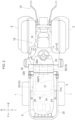
FIG. 2 ] A plan view illustrating the entirety of the tractor. - [
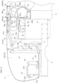
FIG. 3 ] A side view illustrating a motor unit. - [
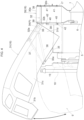
FIG. 4 ] A side view illustrating support structures of a front bonnet and a back bonnet. - [
FIG. 5 ] A front view illustrating the support structure of the back bonnet. - [
FIG. 6 ] A perspective view illustrating the back bonnet, a bonnet support member, and a partition member in an exploded state. - An embodiment that is one example of the present invention is described below based on the drawings.
- Note that in the following description, in regards to a traveling vehicle body of a tractor, the direction of arrow F illustrated in
FIGS. 1 and2 is defined as "vehicle-body front", the direction of arrow B is defined as "vehicle-body back", the direction of arrow U illustrated inFIG. 1 is defined as "vehicle-body up", the direction of arrow D is defined as "vehicle-body down", the direction of arrow L illustrated inFIG. 2 is defined as "vehicle-body left", and the direction of arrow R is defined as "vehicle-body right". - As illustrated in
FIGS. 1 and2 , the tractor is provided with a travelingvehicle body 3 supported by a pair of left and rightfront wheels 1, which can be steered and driven, and a pair of left andright back wheels 2, which can be driven. A vehicle body frame 4 of thetraveling vehicle body 3 is constituted by anengine 5, aflywheel housing 6 connected to a back portion of theengine 5, aclutch housing 7 connected to a back portion of theflywheel housing 6, atransmission case 7a connected to a back portion of theclutch housing 7, and afront frame 8 connected to a lower portion of theengine 5. Amotor unit 9 provided with theengine 5 is formed in a front portion of thetraveling vehicle body 3. A driver'sseat 10 and adriving unit 12, which is provided with asteering wheel 11 whereby a steering operation of thefront wheels 1 is performed, are formed in a back portion of thetraveling vehicle body 3. A linkingmechanism 13, which connects a work apparatus such as a rotary tilling apparatus (not illustrated) in a manner enabling a raising and lowering operation of the work apparatus, and apower takeoff shaft 14, which takes power from theengine 5 and outputs this to the connected work apparatus, are provided in a back portion of the transmission case 7a. 20 illustrated inFIGS. 1 and2 is a ROPS frame. TheROPS frame 20 is configured to be able to change attitudes between a storage attitude, which is a collapsed state of surrounding themotor unit 9, and a usage attitude, which is a raised state. - As illustrated in
FIGS. 1 and3 , themotor unit 9 is provided with anengine compartment 15. Theengine compartment 15 is formed by anengine bonnet 16, which covers theengine compartment 15 from above, the front, and both horizontal sides; apartition member 17 that forms a partition between theengine compartment 15 and thedriving unit 12; and the like. - As illustrated in
FIGS. 1 ,2 and3 , theengine 5, aradiator 18 that cools theengine 5, a first exhaust-gas cleaning apparatus (DPF) 21 and second exhaust-gas cleaning apparatus (SCR) 22 that perform cleaning processes of exhaust gas exhausted by theengine 5, a reducing-agent tank 23, a reducing-agent pump 24, and abattery 25 are provided in theengine compartment 15. - As illustrated in
FIGS. 1 ,2 , and3 , theradiator 18 is provided in front of theengine 5. A blowing action of arotary fan 19 positioned between theradiator 18 and theengine 5 introduces cooling air from outside theengine compartment 15 to inside the engine compartment and supplies the cooling air to theradiator 18. The cooling air is supplied to theradiator 18 in a state of the cooling air passing through theradiator 18 from front to back. In theradiator 18, engine cooling water is cooled by heat exchange between the supplied cooling air and the engine cooling water. Theengine 5 is cooled by the cooled engine cooling water being supplied to theengine 5. - The
engine 5 is a diesel engine. As illustrated inFIGS. 2 and3 , the first exhaust-gas cleaning apparatus 21 is provided above theengine 5 in a state wherein a longitudinal direction of the first exhaust-gas cleaning apparatus adopts a vehicle-body horizontal orientation. Asupport member 26 is erected on theflywheel housing 6. A lower portion of the first exhaust-gas cleaning apparatus 21 is supported by asupport arm 26a provided to thesupport member 26. The first exhaust-gas cleaning apparatus 21 is supported by theflywheel housing 6 of the vehicle body frame 4 via thesupport member 26. An exhaust-gas suctioning portion 21a, which is provided to a part on one end side, in a vehicle-body horizontal width direction, of the first exhaust-gas cleaning apparatus 21, and an exhaust-gasexhausting portion 5a, which is provided to theengine 5, are connected. An exhaust-gas discharging portion 21b is provided to a part on another end side, in the vehicle-body horizontal width direction, of the first exhaust-gas cleaning apparatus 21. - In the first exhaust-
gas cleaning apparatus 21, the exhaust gas exhausted by theengine 5 from the exhaust-gasexhausting portion 5a is suctioned by the exhaust-gas suctioning portion 21a into the apparatus, and diesel microparticles included in the suctioned exhaust gas are collected by a collection filter (not illustrated). This performs an exhaust-gas cleaning process of decreasing the diesel microparticles. The exhaust gas subjected to the cleaning process is discharged from the exhaust-gas discharging portion 21b. - As illustrated in
FIGS. 2 and3 , the second exhaust-gas cleaning apparatus 22 is provided behind theengine 5 in a state wherein a longitudinal direction of the second exhaust-gas cleaning apparatus adopts the vehicle-body horizontal orientation. A front portion of the second exhaust-gas cleaning apparatus 22 is supported by astrut portion 26b provided to thesupport member 26. The second exhaust-gas cleaning apparatus 22 is supported by theflywheel housing 6 of the vehicle body frame 4 via thesupport member 26. An exhaust-gas introduction portion 22a, which is provided to a part on one end side, in the vehicle-body horizontal width direction, of the second exhaust-gas cleaning apparatus 22, and the exhaust-gas discharging portion 21b of the first exhaust-gas cleaning apparatus 21 are connected by a connectingpipe 27. An exhaust-gas discharging portion 22b is provided to a part on another end side, in the vehicle-body horizontal width direction, of the second exhaust-gas cleaning apparatus 22. - In the second exhaust-
gas cleaning apparatus 22, the exhaust gas discharged by the first exhaust-gas cleaning apparatus 21 from the exhaust-gas discharging portion 21b is supplied by the connectingpipe 27 to the exhaust-gas introduction portion 22a and introduced by the exhaust-gas introduction portion 22a into the apparatus, and the introduced exhaust gas is subjected to the cleaning process by a reducing agent. Specifically, aqueous urea as the reducing agent is injected into the introduced exhaust gas, hydrolyzing the exhaust gas. This performs an exhaust-gas cleaning process of decreasing nitrogen oxides included in the exhaust gas. The exhaust gas subjected to the cleaning process is exhausted from the exhaust-gas discharging portion 22b to a vehicle-body horizontal outer side. - As illustrated in
FIGS. 2 and3 , the reducing-agent tank 23, the reducing-agent pump 24, and thebattery 25 are provided on a front side of theengine 5. In the present embodiment, the reducing-agent tank 23, the reducing-agent pump 24, and thebattery 25 are lined up in the vehicle-body horizontal width direction. Asupport plate 28 is provided on an upper side of thefront frame 8. The reducing-agent tank 23 is supported by thesupport plate 28 via atank case 23a. The reducing-agent tank 23 has a pourtube 23b that extends forward and upward from an upper portion of the reducing-agent tank 23 and stores the aqueous urea as the reducing agent by the aqueous urea being poured in from the pourtube 23b. The reducing-agent pump 24 extracts the aqueous urea stored in the reducing-agent tank 23 from the reducing-agent tank 23 and supplies the extracted aqueous urea to the second exhaust-gas cleaning apparatus 22 via a hose (not illustrated) extending from the reducing-agent pump 24 to the second exhaust-gas cleaning apparatus 22. - As illustrated in
FIGS. 1 ,2 , and3 , theengine bonnet 16 has aback bonnet 30, which covers a backengine compartment portion 15B-wherein the second exhaust-gas cleaning apparatus 22 is positioned-of theengine compartment 15, and afront bonnet 31, which covers a frontengine compartment portion 15F-positioned on a vehicle-body front side of the backengine compartment portion 15B-of theengine compartment 15. The frontengine compartment portion 15F houses the first exhaust-gas cleaning apparatus 21, theengine 5, theradiator 18, the reducing-agent tank 23, the reducing-agent pump 24, and thebattery 25. Thefront bonnet 31 and theback bonnet 30 are configured as separate bodies. - As illustrated in
FIGS. 1 ,2 , and3 , thefront bonnet 31 has a fronttop plate portion 31a that covers the frontengine compartment portion 15F from above, afront grille portion 31b that extends downward from a front portion of the fronttop plate portion 31a and covers the frontengine compartment portion 15F from the front, and left and right frontside plate portions 31c that extend downward from both horizontal side portions of the fronttop plate portion 31a and cover the frontengine compartment portion 15F from both horizontal sides. - The
front bonnet 31 is supported in a state wherein it can be opened and closed. - Specifically, as illustrated in
FIGS. 2 ,3 , and4 , abonnet support member 32 extending forward from an upper portion of thepartition member 17 is provided in a back portion of theengine compartment 15. As illustrated inFIG. 6 , thebonnet support member 32 is configured by combining a plurality of steel members extending in a vehicle-body front-back direction and a plurality of steel members extending in the vehicle-body horizontal width direction. As illustrated inFIGS. 3 and6 , apivot shaft 34 extending in the vehicle-body horizontal width direction is provided across a connectingportion 33, provided to a back end portion of thefront bonnet 31, and a front portion of thebonnet support member 32. Thefront bonnet 31 is supported by thebonnet support member 32 in a state of being able to swing between a raised, open state-wherein, as illustrated by the solid lines inFIG. 4 , theengine compartment 15 is opened by using, as a swinging fulcrum, a pivot shaft core P extending in the vehicle-body horizontal width direction of the pivot shaft 34- and a lowered, closed state-wherein, as illustrated by the dot-dot-dash lines inFIG. 4 , theengine compartment 15 is closed. - As illustrated in
FIG. 3 , asupport member 35 extends forward, passing above theengine 5, from thesupport member 26 of the first exhaust-gas cleaning apparatus 21 and the second exhaust-gas cleaning apparatus 22. Asupport rod 36 that causes thesupport member 35 to support thebonnet support member 32 is connected across anarm portion 35a provided to a front portion of thesupport member 35 and anarm portion 32a provided to the front portion of thebonnet support member 32. Adamper 37 that biases thefront bonnet 31 to the open state is connected across thearm portion 35a and an inner portion of thefront bonnet 31. - As illustrated in
FIGS. 1 ,2 , and3 , theback bonnet 30 has a backtop plate portion 30a, which covers the backengine compartment portion 15B from above, and left and right backside plate portions 30b, which cover the backengine compartment portion 15B from both horizontal sides. As illustrated inFIG. 6 , the backtop plate portion 30a and the left and right backside plate portions 30b are configured as separate bodies. The backtop plate portion 30a and the left and right backside plate portions 30b are constituted by sheet-metal members. - As illustrated in
FIGS. 4 and5 , theback bonnet 30 is configured to be supported by thepartition member 17, thebonnet support member 32, and side-plate support members 38. - Specifically, as illustrated in
FIGS. 4 and5 , the side-plate support members 38 extend upward from both horizontal side portions of theflywheel housing 6. Upper end portions of the side-plate support members 38 are connected to a front side portion of thebonnet support member 32, and the side-plate support members 38 are configured to serve as support members of thebonnet support member 32. - As illustrated in
FIG. 6 , connectingportions 39 are respectively provided to a front portion and a back portion of the backtop plate portion 30a. In the present embodiment, the front portion and the back portion of the backtop plate portion 30a are each provided with two connectingportions 39. As illustrated inFIGS. 3 ,4 , and5 , the backtop plate portion 30a is supported by thepartition member 17 and thebonnet support member 32 by the connectingportions 39 of the back portion being pin-connected to thepartition member 17 and the connectingportions 39 of the front portion being pin-connected to asupport portion 32b provided to the front portion of thebonnet support member 32. - As illustrated in
FIG. 6 , at each of the left and right backside plate portions 30b, afront connecting portion 40 is provided to a front portion of the backside plate portion 30b and aback connecting portion 41 is provided to a back portion of the backside plate portion 30b. In the present embodiment, two front connectingportions 40 and two back connectingportions 41 are provided. As illustrated inFIGS. 4 and5 , the left and right backside plate portions 30b are each supported by the side-plate support member 38 and thepartition member 17 by thefront connecting portion 40 being connected to the side-plate support member 38 by a connectingbolt 42 and theback connecting portion 41 being pin-connected to thepartition member 17. - As illustrated by the solid lines in
FIG. 1 and the dot-dot-dash lines inFIG. 4 , thefront bonnet 31 is configured so in the closed state, aback portion 31d of the frontside plate portion 31c of thefront bonnet 31 is positioned on a horizontal outer side of the connectingbolt 42 so as to cover the connectingbolt 42. The frontside plate portion 31c of thefront bonnet 31 prevents exposure of and water leakage into the connectingbolt 42. - The
engine bonnet 16 has theback bonnet 30, which covers the backengine compartment portion 15B-wherein theflywheel housing 6 is positioned-of theengine compartment 15, and thefront bonnet 31, which covers the frontengine compartment portion 15F-positioned on the vehicle-body front side of the backengine compartment portion 15B-of theengine compartment 15. Thefront bonnet 31 and theback bonnet 30 are configured as separate bodies. Thefront bonnet 31 is supported in a state wherein it can swing open and closed. -
- (1) The above embodiment illustrates an example wherein the
front bonnet 31 is supported so as to be able to swing open and closed, up and down, by using as a swinging fulcrum the pivot shaft core P in the vehicle-body horizontal orientation provided to the back end portion of thefront bonnet 31. However, the present invention is not limited thereto. For example, the front bonnet may be supported so as to be able to swing open and closed, up and down, by using as a swinging fulcrum a pivot shaft core in the vehicle-body horizontal orientation positioned in a front end portion of thefront bonnet 31. Alternatively, the front bonnet may be supported so as to be able to swing open and closed by using as a swinging fulcrum a pivot shaft core positioned in a state of extending in the vehicle-body front-back direction to a horizontal side portion of thefront bonnet 31. - (2) The above embodiment illustrates an example wherein the back
top plate portion 30a and the left and right backside plate portions 30b are configured as separate bodies. However, these may be integrally configured. - (3) The above embodiment illustrates an example of adopting a configuration wherein the connecting
bolt 42 is covered from the horizontal side by theback portion 31d of thefront bonnet 31 in the closed state. However, this configuration does not need to be adopted. - (4) The above embodiment illustrates an example wherein the reducing-
agent tank 23 and the reducing-agent pump 24 are provided on the front side of theengine 5 in the frontengine compartment portion 15F, but the present invention is not limited thereto. - For example, the reducing-
agent tank 23 and the reducing-agent pump 24 may be provided in any location, such as outside theengine compartment 15. - The present invention can be applied in tractors provided with an engine bonnet forming an engine compartment, a first exhaust-gas cleaning apparatus provided above an engine in the engine compartment, and a second exhaust-gas cleaning apparatus provided behind the engine.
Claims (5)
- A tractor, comprising: an engine bonnet forming an engine compartment; anda first exhaust-gas cleaning apparatus, which is provided above an engine in the engine compartment and subjects exhaust gas from the engine to a cleaning process, and second exhaust-gas cleaning apparatus, which is provided behind the engine and subjects the exhaust gas from the engine to a cleaning process; whereinthe engine bonnet has a back bonnet, which covers a back engine compartment portion-wherein the second exhaust-gas cleaning apparatus is positioned-of the engine compartment and a front bonnet, which is configured as a separate body from the back bonnet in a state of covering a front engine compartment portion-positioned on a vehicle-body front side of the back engine compartment portion-of the engine compartment; andthe front bonnet is supported in a state wherein it can swing open and closed.
- The tractor of claim 1, wherein the front bonnet is supported in a state of being able to swing open and closed, up and down, by using as a swinging fulcrum a pivot shaft core in a vehicle-body horizontal orientation provided to a back end portion of the front bonnet.
- The tractor of claim 2, wherein the front bonnet has a front top plate portion and front side plate portions that extend downward from left and right side portions of the front top plate portion,the back bonnet has a back top plate portion that covers the back engine compartment portion from above and left and right back side plate portions that cover the back engine compartment portion from both horizontal sides,provided is a connecting bolt that connects a front portion of the back side plate portion to a support member, andthe front bonnet is configured so in a closed state, a back portion of the front side plate portion is positioned on a horizontal outer side of the connecting bolt so as to cover the connecting bolt.
- The tractor of any one among claims 1 to 3, wherein the back bonnet has a back top plate portion that covers the back engine compartment portion from above and left and right back side plate portions that cover the back engine compartment portion from both horizontal sides, and
the back top plate portion and the left and right back side plate portions are configured as separate bodies. - The tractor of any one among claims 1 to 4, wherein the second exhaust-gas cleaning apparatus is configured to use a reducing agent to subject the exhaust gas from the engine to the cleaning process, and
a reducing-agent tank and,a reducing-agent pump, which supplies the reducing agent stored in the reducing-agent tank to the second exhaust-gas cleaning apparatus, are provided on a front side of the engine in the front engine compartment portion.
Priority Applications (1)
| Application Number | Priority Date | Filing Date | Title |
|---|---|---|---|
| EP22203955.4A EP4361003B1 (en) | 2022-10-26 | 2022-10-26 | Tractor |
Applications Claiming Priority (1)
| Application Number | Priority Date | Filing Date | Title |
|---|---|---|---|
| EP22203955.4A EP4361003B1 (en) | 2022-10-26 | 2022-10-26 | Tractor |
Publications (2)
| Publication Number | Publication Date |
|---|---|
| EP4361003A1 true EP4361003A1 (en) | 2024-05-01 |
| EP4361003B1 EP4361003B1 (en) | 2025-10-22 |
Family
ID=84688357
Family Applications (1)
| Application Number | Title | Priority Date | Filing Date |
|---|---|---|---|
| EP22203955.4A Active EP4361003B1 (en) | 2022-10-26 | 2022-10-26 | Tractor |
Country Status (1)
| Country | Link |
|---|---|
| EP (1) | EP4361003B1 (en) |
Citations (6)
| Publication number | Priority date | Publication date | Assignee | Title |
|---|---|---|---|---|
| JP2012051518A (en) * | 2010-09-02 | 2012-03-15 | Yanmar Co Ltd | Tractor |
| JP4917854B2 (en) * | 2006-09-05 | 2012-04-18 | ヤンマー株式会社 | Work vehicle |
| WO2014081196A1 (en) * | 2012-11-20 | 2014-05-30 | 대동공업 주식회사 | Hinge assembly for opening and closing bonnet of farm work vehicle and hinge structure for bonnet of farm work vehicle by this hinge assembly |
| WO2015093375A1 (en) * | 2013-12-17 | 2015-06-25 | ヤンマー株式会社 | Working vehicle |
| JP2015227072A (en) * | 2014-05-30 | 2015-12-17 | 三菱マヒンドラ農機株式会社 | Work vehicle |
| JP2017024436A (en) * | 2015-07-15 | 2017-02-02 | 三菱マヒンドラ農機株式会社 | Work vehicle |
-
2022
- 2022-10-26 EP EP22203955.4A patent/EP4361003B1/en active Active
Patent Citations (7)
| Publication number | Priority date | Publication date | Assignee | Title |
|---|---|---|---|---|
| JP4917854B2 (en) * | 2006-09-05 | 2012-04-18 | ヤンマー株式会社 | Work vehicle |
| JP2012051518A (en) * | 2010-09-02 | 2012-03-15 | Yanmar Co Ltd | Tractor |
| WO2014081196A1 (en) * | 2012-11-20 | 2014-05-30 | 대동공업 주식회사 | Hinge assembly for opening and closing bonnet of farm work vehicle and hinge structure for bonnet of farm work vehicle by this hinge assembly |
| WO2015093375A1 (en) * | 2013-12-17 | 2015-06-25 | ヤンマー株式会社 | Working vehicle |
| JP6188219B2 (en) | 2013-12-17 | 2017-08-30 | ヤンマー株式会社 | Tractor |
| JP2015227072A (en) * | 2014-05-30 | 2015-12-17 | 三菱マヒンドラ農機株式会社 | Work vehicle |
| JP2017024436A (en) * | 2015-07-15 | 2017-02-02 | 三菱マヒンドラ農機株式会社 | Work vehicle |
Also Published As
| Publication number | Publication date |
|---|---|
| EP4361003B1 (en) | 2025-10-22 |
Similar Documents
| Publication | Publication Date | Title |
|---|---|---|
| US20230159109A1 (en) | Tractor | |
| CN103380252B (en) | construction machinery | |
| US8919486B2 (en) | Hydraulic excavator | |
| WO2014069026A1 (en) | Construction vehicle equipped with exhaust-gas post-processing device | |
| JP5442829B1 (en) | Excavator | |
| CN103608524A (en) | Construction machine | |
| US20150176451A1 (en) | Cooling structure for urea aqueous solution conduit | |
| EP2746464A1 (en) | Wheel loader | |
| KR102183434B1 (en) | tractor | |
| JP5805023B2 (en) | Work vehicle | |
| US20160032562A1 (en) | Wheel loader | |
| CN103797193A (en) | Wheel loader | |
| US9540979B2 (en) | Working vehicle | |
| JP5893524B2 (en) | Work vehicle | |
| EP4361003B1 (en) | Tractor | |
| EP2136004B1 (en) | Excavating machine | |
| JP5414871B1 (en) | Excavator | |
| CN113329933B (en) | Work vehicle | |
| JP2014065441A (en) | Work vehicle | |
| CN217679317U (en) | Excavator | |
| WO2015122547A1 (en) | Hydraulic shovel | |
| EP4361411A1 (en) | Tractor | |
| JP2014181550A (en) | Work vehicle | |
| JP5470732B2 (en) | Vehicle powertrain arrangement structure | |
| JP2026060418A (en) | Working machinery |
Legal Events
| Date | Code | Title | Description |
|---|---|---|---|
| PUAI | Public reference made under article 153(3) epc to a published international application that has entered the european phase |
Free format text: ORIGINAL CODE: 0009012 |
|
| STAA | Information on the status of an ep patent application or granted ep patent |
Free format text: STATUS: THE APPLICATION HAS BEEN PUBLISHED |
|
| AK | Designated contracting states |
Kind code of ref document: A1 Designated state(s): AL AT BE BG CH CY CZ DE DK EE ES FI FR GB GR HR HU IE IS IT LI LT LU LV MC ME MK MT NL NO PL PT RO RS SE SI SK SM TR |
|
| STAA | Information on the status of an ep patent application or granted ep patent |
Free format text: STATUS: REQUEST FOR EXAMINATION WAS MADE |
|
| 17P | Request for examination filed |
Effective date: 20240507 |
|
| RBV | Designated contracting states (corrected) |
Designated state(s): AL AT BE BG CH CY CZ DE DK EE ES FI FR GB GR HR HU IE IS IT LI LT LU LV MC ME MK MT NL NO PL PT RO RS SE SI SK SM TR |
|
| GRAP | Despatch of communication of intention to grant a patent |
Free format text: ORIGINAL CODE: EPIDOSNIGR1 |
|
| STAA | Information on the status of an ep patent application or granted ep patent |
Free format text: STATUS: GRANT OF PATENT IS INTENDED |
|
| INTG | Intention to grant announced |
Effective date: 20250707 |
|
| GRAS | Grant fee paid |
Free format text: ORIGINAL CODE: EPIDOSNIGR3 |
|
| GRAA | (expected) grant |
Free format text: ORIGINAL CODE: 0009210 |
|
| STAA | Information on the status of an ep patent application or granted ep patent |
Free format text: STATUS: THE PATENT HAS BEEN GRANTED |
|
| AK | Designated contracting states |
Kind code of ref document: B1 Designated state(s): AL AT BE BG CH CY CZ DE DK EE ES FI FR GB GR HR HU IE IS IT LI LT LU LV MC ME MK MT NL NO PL PT RO RS SE SI SK SM TR |
|
| REG | Reference to a national code |
Ref country code: CH Ref legal event code: F10 Free format text: ST27 STATUS EVENT CODE: U-0-0-F10-F00 (AS PROVIDED BY THE NATIONAL OFFICE) Effective date: 20251022 Ref country code: GB Ref legal event code: FG4D |
|
| REG | Reference to a national code |
Ref country code: IE Ref legal event code: FG4D |
|
| REG | Reference to a national code |
Ref country code: DE Ref legal event code: R096 Ref document number: 602022023389 Country of ref document: DE |
|
| PGFP | Annual fee paid to national office [announced via postgrant information from national office to epo] |
Ref country code: DE Payment date: 20251203 Year of fee payment: 4 |
|
| PGFP | Annual fee paid to national office [announced via postgrant information from national office to epo] |
Ref country code: AT Payment date: 20260113 Year of fee payment: 4 |
|
| PGFP | Annual fee paid to national office [announced via postgrant information from national office to epo] |
Ref country code: FR Payment date: 20251125 Year of fee payment: 4 |
|
| REG | Reference to a national code |
Ref country code: NL Ref legal event code: MP Effective date: 20251022 |
|
| PG25 | Lapsed in a contracting state [announced via postgrant information from national office to epo] |
Ref country code: NL Free format text: LAPSE BECAUSE OF FAILURE TO SUBMIT A TRANSLATION OF THE DESCRIPTION OR TO PAY THE FEE WITHIN THE PRESCRIBED TIME-LIMIT Effective date: 20251022 |
|
| PG25 | Lapsed in a contracting state [announced via postgrant information from national office to epo] |
Ref country code: ES Free format text: LAPSE BECAUSE OF FAILURE TO SUBMIT A TRANSLATION OF THE DESCRIPTION OR TO PAY THE FEE WITHIN THE PRESCRIBED TIME-LIMIT Effective date: 20251022 |
|
| REG | Reference to a national code |
Ref country code: LT Ref legal event code: MG9D |
|
| PG25 | Lapsed in a contracting state [announced via postgrant information from national office to epo] |
Ref country code: NO Free format text: LAPSE BECAUSE OF FAILURE TO SUBMIT A TRANSLATION OF THE DESCRIPTION OR TO PAY THE FEE WITHIN THE PRESCRIBED TIME-LIMIT Effective date: 20260122 |
|
| PG25 | Lapsed in a contracting state [announced via postgrant information from national office to epo] |
Ref country code: FI Free format text: LAPSE BECAUSE OF FAILURE TO SUBMIT A TRANSLATION OF THE DESCRIPTION OR TO PAY THE FEE WITHIN THE PRESCRIBED TIME-LIMIT Effective date: 20251022 Ref country code: HR Free format text: LAPSE BECAUSE OF FAILURE TO SUBMIT A TRANSLATION OF THE DESCRIPTION OR TO PAY THE FEE WITHIN THE PRESCRIBED TIME-LIMIT Effective date: 20251022 Ref country code: AT Free format text: LAPSE BECAUSE OF FAILURE TO SUBMIT A TRANSLATION OF THE DESCRIPTION OR TO PAY THE FEE WITHIN THE PRESCRIBED TIME-LIMIT Effective date: 20251022 |
|
| REG | Reference to a national code |
Ref country code: AT Ref legal event code: MK05 Ref document number: 1848930 Country of ref document: AT Kind code of ref document: T Effective date: 20251022 |
|
| PG25 | Lapsed in a contracting state [announced via postgrant information from national office to epo] |
Ref country code: RS Free format text: LAPSE BECAUSE OF FAILURE TO SUBMIT A TRANSLATION OF THE DESCRIPTION OR TO PAY THE FEE WITHIN THE PRESCRIBED TIME-LIMIT Effective date: 20260122 |
|
| PG25 | Lapsed in a contracting state [announced via postgrant information from national office to epo] |
Ref country code: IS Free format text: LAPSE BECAUSE OF FAILURE TO SUBMIT A TRANSLATION OF THE DESCRIPTION OR TO PAY THE FEE WITHIN THE PRESCRIBED TIME-LIMIT Effective date: 20260222 |
|
| PG25 | Lapsed in a contracting state [announced via postgrant information from national office to epo] |
Ref country code: PT Free format text: LAPSE BECAUSE OF FAILURE TO SUBMIT A TRANSLATION OF THE DESCRIPTION OR TO PAY THE FEE WITHIN THE PRESCRIBED TIME-LIMIT Effective date: 20260223 |
|
| PG25 | Lapsed in a contracting state [announced via postgrant information from national office to epo] |
Ref country code: PL Free format text: LAPSE BECAUSE OF FAILURE TO SUBMIT A TRANSLATION OF THE DESCRIPTION OR TO PAY THE FEE WITHIN THE PRESCRIBED TIME-LIMIT Effective date: 20251022 |
|
| PG25 | Lapsed in a contracting state [announced via postgrant information from national office to epo] |
Ref country code: LV Free format text: LAPSE BECAUSE OF FAILURE TO SUBMIT A TRANSLATION OF THE DESCRIPTION OR TO PAY THE FEE WITHIN THE PRESCRIBED TIME-LIMIT Effective date: 20251022 |
|
| PG25 | Lapsed in a contracting state [announced via postgrant information from national office to epo] |
Ref country code: BG Free format text: LAPSE BECAUSE OF FAILURE TO SUBMIT A TRANSLATION OF THE DESCRIPTION OR TO PAY THE FEE WITHIN THE PRESCRIBED TIME-LIMIT Effective date: 20251022 |