EP4360957A1 - Garnish for instrument panel - Google Patents
Garnish for instrument panel Download PDFInfo
- Publication number
- EP4360957A1 EP4360957A1 EP23190925.0A EP23190925A EP4360957A1 EP 4360957 A1 EP4360957 A1 EP 4360957A1 EP 23190925 A EP23190925 A EP 23190925A EP 4360957 A1 EP4360957 A1 EP 4360957A1
- Authority
- EP
- European Patent Office
- Prior art keywords
- garnish
- peripheral portion
- gate
- instrument panel
- frame
- Prior art date
- Legal status (The legal status is an assumption and is not a legal conclusion. Google has not performed a legal analysis and makes no representation as to the accuracy of the status listed.)
- Granted
Links
Images




Classifications
-
- B—PERFORMING OPERATIONS; TRANSPORTING
- B60—VEHICLES IN GENERAL
- B60R—VEHICLES, VEHICLE FITTINGS, OR VEHICLE PARTS, NOT OTHERWISE PROVIDED FOR
- B60R11/00—Arrangements for holding or mounting articles, not otherwise provided for
- B60R11/02—Arrangements for holding or mounting articles, not otherwise provided for for radio sets, television sets, telephones, or the like; Arrangement of controls thereof
- B60R11/0229—Arrangements for holding or mounting articles, not otherwise provided for for radio sets, television sets, telephones, or the like; Arrangement of controls thereof for displays, e.g. cathodic tubes
- B60R11/0235—Arrangements for holding or mounting articles, not otherwise provided for for radio sets, television sets, telephones, or the like; Arrangement of controls thereof for displays, e.g. cathodic tubes of flat type, e.g. LCD
-
- B—PERFORMING OPERATIONS; TRANSPORTING
- B60—VEHICLES IN GENERAL
- B60R—VEHICLES, VEHICLE FITTINGS, OR VEHICLE PARTS, NOT OTHERWISE PROVIDED FOR
- B60R13/00—Elements for body-finishing, identifying, or decorating; Arrangements or adaptations for advertising purposes
- B60R13/02—Internal Trim mouldings ; Internal Ledges; Wall liners for passenger compartments; Roof liners
- B60R13/0256—Dashboard liners
-
- B—PERFORMING OPERATIONS; TRANSPORTING
- B60—VEHICLES IN GENERAL
- B60R—VEHICLES, VEHICLE FITTINGS, OR VEHICLE PARTS, NOT OTHERWISE PROVIDED FOR
- B60R11/00—Arrangements for holding or mounting articles, not otherwise provided for
- B60R2011/0001—Arrangements for holding or mounting articles, not otherwise provided for characterised by position
- B60R2011/0003—Arrangements for holding or mounting articles, not otherwise provided for characterised by position inside the vehicle
- B60R2011/0005—Dashboard
Definitions
- the present invention relates to a garnish for an instrument panel.
- Various types of equipment such as audio equipment and an air-conditioning operation unit are disposed in an instrument panel of an automobile or the like.
- These types of in-vehicle equipment are usually removably fixed so that the equipment is able to be maintained or replaced, and mating portions around mounting portions of the equipment are each covered with a garnish separate from an instrument panel body in order to maintain a favorable interior appearance.
- the garnish is also removably provided on the instrument panel body, and the garnish is configured to be removed before removal of the in-vehicle equipment so that the mounting portion of the in-vehicle equipment is exposed.
- Patent Literature 1 describes an instrument panel in which a garnish is attached with a peripheral edge thereof overlapped on a panel body and an edge portion of an attachment member such as another garnish, the instrument panel being characterized in that a rib stands upright on the edge portion of the attachment member and the garnish is attached by hooking the peripheral edge of the garnish on the rib.
- a garnish is required to exhibit impact resistance, which makes it necessary to use a resin material that is excellent in impact resistance to mold the garnish.
- resin material that is excellent in impact resistance
- PC/ABS resin a polymer alloy of polycarbonate and acrylonitrile-butadiene-styrene
- the present inventors have found that the expected impact resistance fails to be exhibited when a garnish is molded from a PC/ABS resin.
- an object of the present invention is to provide a garnish for an instrument panel, the garnish exhibiting excellent impact resistance even though it is molded from a PC/ABS resin.
- the present invention provides a garnish in a form of a frame configured to cover a periphery of in-vehicle equipment disposed around a middle of an instrument panel, the garnish including an opening portion around a middle defined by an upper frame, a lower frame, and right and left frames of the garnish, in which respective outer peripheral portions and inner peripheral portions of the upper frame, the lower frame, and the right and left frames project toward the in-vehicle equipment, the garnish is formed of a polymer alloy of polycarbonate and acrylonitrile-butadiene-styrene (a PC/ABS resin), and a gate mark is provided on at least one of the upper frame, the lower frame, and the right and left frames between the outer peripheral portion and the inner peripheral portion, projecting toward the in-vehicle equipment.
- a PC/ABS resin polymer alloy of polycarbonate and acrylonitrile-butadiene-styrene
- a garnish for an instrument panel can exhibit excellent impact resistance even though it is molded from a PC/ABS resin.
- Figure 1 is an example of an instrument panel for a right-hand-drive vehicle, which is provided in a front portion of a vehicle interior.
- a dashboard (not illustrated) including a speedometer, a fuel gauge, and the like is disposed on a right side as viewed by an observer, a decorative panel, that is, cluster panel 2, covering a periphery of the dashboard is provided, and an upper storage box 3 is provided on a left side as viewed by an observer.
- a car navigation system 4 is installed and a decorative panel, that is, garnish 10, covering a periphery of the car navigation system 4, is disposed.
- a decorative panel that is, heater control panel 5, for an air-conditioning unit such as an air conditioner or a heater is disposed below the garnish 10.
- a center louver mechanism 7 is provided on both sides of the garnish 10, serving as a vent of the air-conditioning unit around a middle in the vehicle interior.
- the cluster panel 2, the storage box 3, the garnish 10, and the heater control panel 5 are each molded from a resin, located at a position projecting toward the vehicle interior with respect to the center louver mechanism 7, and provided with a cavity in an internal cross-section to exhibit a buffering action to absorb an impact.
- the garnish 10 which is a thinned frame surrounding a display of the car navigation system 4, is configured to cause the instrument panel body 1 to project toward the vehicle interior.
- the garnish 10 mainly includes, as viewed from a vehicle-interior side, an upper frame 11, a lower frame 12, a right frame 13, and a left frame 14, which define an opening around a middle.
- a longitudinal direction of the garnish 10 is along a vehicle-width direction. In other words, the upper frame 11 and the lower frame 12 are longer than the left and right frames 13, 14.
- a positioning pin 15 projecting from the garnish 10 is inserted into a positioning hole 7 of a bracket 6 of the instrument panel body, and the garnish 10 is fastened by inserting a screw 17 into an attachment hole (not illustrated) of the garnish 10.
- a clip 16 of the garnish 10 is inserted into an engagement hole (not illustrated) of the instrument panel body for fixation.
- each of the upper frame 11, the lower frame 12, the right frame 13, and the left frame 14 of the garnish 10 has an outer peripheral portion and an inner peripheral portion (i.e., a peripheral portion on an opening side) projecting toward the in-vehicle equipment (i.e., an opposite side to the vehicle interior).
- the garnish 10 of the present embodiment is formed of a PC/ABS resin, and gate marks 17, 18, which are attributed to injection molding, are provided on the upper frame 11 and the lower frame 12, respectively, projecting toward the in-vehicle equipment.
- the gate mark 17 of the upper frame 11 is located not on an outer peripheral portion 11a or an inner peripheral portion 11b of the upper frame 11 projecting toward the in-vehicle equipment, but between these portions. Molding the garnish 10 using a submarine gate causes the gate mark 17 to be made at such a position.
- a distance of the gate mark 17 from the outer peripheral portion 11a and the inner peripheral portion 11b is preferably equal to or greater than 2 mm, more preferably equal to or greater than 4 mm.
- injection molding is performed using a PC/ABS resin from a gate opening at the position distant from the outer peripheral portion 11a and the inner peripheral portion 11b, which makes it possible to notably improve the impact resistance of the garnish 10.
- the gate mark 17 be offset to the inner peripheral portion 11b with respect to a center between the outer peripheral portion 11a and the inner peripheral portion 11b of the upper frame 11.
- the gate mark 17 may be a cause of a reduction in impact resistance.
- offsetting the gate mark to the inner peripheral portion 11b on the lower side makes the garnish 10 unlikely to fracture, since if a person in the vehicle hits the garnish 10 due to an accident or the like, it is supposed that the person is likely to hit an upper side of the upper frame 11.
- the gate mark 17 of the upper frame 11 has substantially a plate shape with a width direction thereof being along the longitudinal direction of the garnish 10 and the shape is gradually flared toward the upper frame 11. Injection molding is performed using a gate opening providing the gate mark 17 in such a shape, which makes it possible to prevent the occurrence of a crack in the garnish 10.
- the gate mark 18 of the lower frame 12 is located not on an outer peripheral portion 12a or an inner peripheral portion 12b of the lower frame 12 projecting toward the in-vehicle equipment, but between these portions by virtue of molding using the submarine gate.
- a distance of the gate mark 18 from the outer peripheral portion 12a and the inner peripheral portion 12b is preferably equal to or greater than 2 mm, more preferably equal to or greater than 4 mm.
- injection molding is performed using a PC/ABS resin from a gate opening at a position distant from the outer peripheral portion 12a and the inner peripheral portion 12b, which makes it possible to notably improve the impact resistance of the garnish 10.
- the gate mark 18 be offset to the outer peripheral portion 12a with respect to a center between the outer peripheral portion 12a and the inner peripheral portion 12b of the lower frame 12.
- the gate mark 18 may be a cause of a reduction in impact resistance.
- providing the gate mark on the outer peripheral portion 12a on the lower side makes the garnish 10 unlikely to fracture, since if a person in the vehicle hits the garnish 10 due to an accident or the like, it is supposed that the person is likely to hit an upper side of the lower frame 11.
- the gate mark 18 of the lower frame 12 also has substantially a plate shape with a width direction thereof being along the longitudinal direction of the garnish 10 and the shape is gradually flared toward the lower frame 12.
- the two gate marks 17, 18 exist in the garnish 10. This is because the single garnish 10 is molded from the two gate openings by injection molding. Such injection molding using the two gate openings located at the gate marks 17, 18 causes weld lines 20a, 20b where molten resins meet to be formed at corners of the garnish 10 as illustrated in Figure 7 . Such formation of the weld lines 20a, 20b at the corners of the garnish 10 increases an angle at which the resins meet, thereby making it possible to improve an appearance of a portion corresponding to the weld lines 20a, 20b.
- a height of the gate mark 17 of the upper frame 11 is higher than a height B of the inner peripheral portion 11b of the upper frame.
- the height of the gate mark 17 of the upper frame 11 is lower than a height A of the outer peripheral portion 11a of the upper frame.
- the formation of the gate mark 17 is described with reference to Figure 9 .
- the garnish 10 is injection-molded using a submarine gate 20. This makes it possible to place the gate opening of a mold (not illustrated) not in the projecting outer peripheral portion 11a and inner peripheral portion 11b of the upper frame 11, but at a portion therebetween.
- the gate mark 17a which is higher than the outer peripheral portion 11a of the upper frame as illustrated in Figure 9 immediately after demolding, is able to be cut at a position C lower than the outer peripheral portion 11a of the upper frame with nippers or the like.
- the gate mark may be automatically cut during demolding as described above.
- the gate mark 18 of the lower frame 12 may be likewise formed and cut.
- a height of the gate mark 18 of the lower frame 12 is higher than the height B of the inner peripheral portion 12b of the lower frame.
- the height of the gate mark 18 of the lower frame 12 is lower than a height A of the outer peripheral portion 12a of the lower frame.
- a plate molded article (180 mm x 250 mm x thickness 3 mm, a fine gate plate) of a PC/ABS resin (manufactured by Mitsubishi Engineering-Plastics Corporation, MB2215R) was produced by injection molding and strip specimens (10 mm x 70 mm x thickness 3 mm) in a resin flowing direction (an MD direction) and a vertical direction (a TD direction) were cut out of the plate molded article using an automatic sample molding machine.
- Figure 11 illustrates a spot at which the specimen in the TD direction was collected
- Figure 12 illustrates a spot at which the specimen in the MD direction was collected.
- a plate molded article 30 is an article molded from a resin flowing in an arrow direction from a gate opening 32 of an injection molding machine.
- a strip specimen 31 in the TD direction is a specimen cut such that a longitudinal direction of the strip specimen was vertical to the flow direction.
- a distance a from an end surface of the plate molded article 30 on a side toward the gate opening 32 to a centerline of a first specimen (TD1) in the TD direction was 20 mm.
- a strip specimen 41 in the MD direction is a specimen cut out of the plate molded article 30 such that a longitudinal direction of the strip specimen 41 was the same as the flowing direction indicated by an arrow as illustrated in Figure 12 .
- a distance b from a centerline of the plate molded article 30 to a centerline of a first specimen (MD1) in the MD direction was 67.5 mm.
- a specimen fracture morphology was different between the MD direction and the TD direction and the Charpy impact values of the specimens in the TD direction were equal to or less than a half of those of the specimens in the MD direction. Accordingly, molding a component with a high impact resistance from a PC/ABS resin requires measures for maintaining a high impact resistance value even in the TD direction.
- a Charpy impact value of each specimen in the MD direction and the TD direction was measured as in Test Example 1, except that a PC resin (manufactured by Mitsubishi Engineering-Plastics Corporation, S-3000R) was used in place of the PC/ABS resin.
- the PC resin had anisotropy depending on the resin flowing direction, as the PC/ABS resin in Test Example 1.
- Charpy impact value of the PC resin assuming that an average of the Charpy impact values of the specimens in the MD direction in Test Example 1 was 100, an average of the specimens in the MD direction was 142 and an average of the specimens in the TD direction was 144. All the specimens of the PC resin suffered P fracture. From this result, the anisotropy of the PC/ABS resin is thought to originate from an ABS resin and is speculated to be attributed to, in particular, an orientation of rubber in the ABS resin.
- a strip specimen in the TD direction with a gate opening placed in the specimen was produced and a Charpy impact test was performed.
- a plate molded article was molded using a submarine gate 62 (gate opening: 6 mm x 2.5 mm) such that a gate opening 63 of the submarine gate 62 was placed inside with respect to an end surface of the plate molded article 60 as illustrated in Figure 14 .
- CK43-D4 manufactured by Techno-UMG Co., Ltd. was used as the PC/ABS resin.
- JSW180ton manufactured by The Japan Steel Works, Ltd. was used as the molding machine and a one-gate plate-shaped mold was used as the mold.
- a distance L between the gate opening 63 and the end surface of the plate molded article 60 was changed by changing a shape of a PL surface (a mating surface of the mold) of a portion that is a loose piece (not illustrated).
- the specimen 61 was in the form of a strip specimen in the TD direction (80 mm x 10 mm x thickness 3 mm) as illustrated in Figure 14 and was cut out along the end surface of the plate molded article 60.
- Table 1 Result of Charpy Impact Test of Test Example 3 Gate Shape Side Submarine Gate Distance L [mm] 0 0 2 4.4 Charpy Impact Value [Relative Value] 20 28 72 190 Fracture Morphology C C C C Plastic Deformation No No Yes Yes
- specimens 50 with the gate distance L of 0 mm and specimens 52 with the gate distance L of 2 mm which were molded using the submarine gate, all suffered complete fracture (C fracture).
- C fracture complete fracture
- the specimens 50 with the gate distance L of 0 mm almost no plastically deformed region was observed in a crack occurrence portion, and additionally, the impact resistance was low.
- the specimens 52 with the gate distance L of 2 mm a plastic deformation 53 was observed in a crack occurrence portion, and additionally, the impact resistance was more than twice as high as that of the specimens with the gate distance L of 0 mm as shown in Table 1.
- a specimen molded using the submarine gate should be improved in impact resistance against a width-direction tensile deformation by virtue of the occurrence of a width-direction flow from the gate opening to the end of the specimen.
- An increase in gate distance is speculated to result in an increase in a region having a strong resistance against a width-direction deformation.
Landscapes
- Engineering & Computer Science (AREA)
- Mechanical Engineering (AREA)
- Moulds For Moulding Plastics Or The Like (AREA)
- Injection Moulding Of Plastics Or The Like (AREA)
- Instrument Panels (AREA)
Abstract
Description
- The present invention relates to a garnish for an instrument panel.
- Various types of equipment such as audio equipment and an air-conditioning operation unit are disposed in an instrument panel of an automobile or the like. These types of in-vehicle equipment are usually removably fixed so that the equipment is able to be maintained or replaced, and mating portions around mounting portions of the equipment are each covered with a garnish separate from an instrument panel body in order to maintain a favorable interior appearance. Accordingly, the garnish is also removably provided on the instrument panel body, and the garnish is configured to be removed before removal of the in-vehicle equipment so that the mounting portion of the in-vehicle equipment is exposed.
- For example,
Patent Literature 1 describes an instrument panel in which a garnish is attached with a peripheral edge thereof overlapped on a panel body and an edge portion of an attachment member such as another garnish, the instrument panel being characterized in that a rib stands upright on the edge portion of the attachment member and the garnish is attached by hooking the peripheral edge of the garnish on the rib. - [Patent Literature 1]
JP H05-201274 A - A garnish is required to exhibit impact resistance, which makes it necessary to use a resin material that is excellent in impact resistance to mold the garnish. There are various resin materials excellent in impact resistance and a polymer alloy of polycarbonate and acrylonitrile-butadiene-styrene (hereinafter, also referred to as "PC/ABS resin") is thought to have a high impact resistance. However, the present inventors have found that the expected impact resistance fails to be exhibited when a garnish is molded from a PC/ABS resin.
- Accordingly, in view of the above-described problem, an object of the present invention is to provide a garnish for an instrument panel, the garnish exhibiting excellent impact resistance even though it is molded from a PC/ABS resin.
- To achieve the above-described object, the present invention provides a garnish in a form of a frame configured to cover a periphery of in-vehicle equipment disposed around a middle of an instrument panel, the garnish including an opening portion around a middle defined by an upper frame, a lower frame, and right and left frames of the garnish, in which respective outer peripheral portions and inner peripheral portions of the upper frame, the lower frame, and the right and left frames project toward the in-vehicle equipment, the garnish is formed of a polymer alloy of polycarbonate and acrylonitrile-butadiene-styrene (a PC/ABS resin), and a gate mark is provided on at least one of the upper frame, the lower frame, and the right and left frames between the outer peripheral portion and the inner peripheral portion, projecting toward the in-vehicle equipment.
- Thus, according to the present invention, a garnish for an instrument panel can exhibit excellent impact resistance even though it is molded from a PC/ABS resin.
-
- [
Figure 1] Figure 1 is a front view schematically illustrating an example of an instrument panel attached with a garnish according to the present invention. - [
Figure 2] Figure 2 is a front-side perspective view illustrating the garnish attached to the instrument panel illustrated inFigure 1 . - [
Figure 3] Figure 3 is a rear-side perspective view for explaining a method of attaching the garnish illustrated inFigure 2 to the instrument panel. - [
Figure 4] Figure 4 is a rear-side perspective view of the garnish illustrated inFigure 2 . - [
Figure 5] Figure 5 is an enlarged perspective view of a vicinity of a gate mark located on an upper frame of the garnish illustrated inFigure 4 . - [
Figure 6] Figure 6 is an enlarged perspective view of a vicinity of a gate mark located on a lower frame of the garnish illustrated inFigure 4 . - [
Figure 7] Figure 7 is a rear view of the garnish illustrated inFigure 2 . - [
Figure 8] Figure 8 is a cross-sectional view of the upper frame taken along a line VIII-VIII illustrated inFigure 5 . - [
Figure 9] Figure 9 is a cross-sectional view for explaining formation of the gate mark illustrated inFigure 8 . - [
Figure 10] Figure 10 is a cross-sectional view of the lower frame taken along a line X-X illustrated inFigure 6 . - [
Figure 11] Figure 11 is a plan view illustrating a spot of collecting a specimen in a TD direction in Test Example 1. - [
Figure 12] Figure 12 is a plan view illustrating a spot of collecting a specimen in an MD direction in Test Example 1. - [
Figure 13] Figure 13 is a plan view illustrating an observation result of a fracture morphology of a specimen caused by a Charpy impact test in Test Example 1. - [
Figure 14] Figure 14 is a plan view illustrating a spot at which a specimen molded using a submarine gate in Test Example 3 was collected. - [
Figure 15] Figure 15 is a plan view illustrating a spot at which a specimen molded using a side gate in Test Example 3 was collected. - [
Figure 16] Figure 16 is a plan view illustrating a result of observation of a fracture morphology of a specimen caused by a Charpy impact test in Test Example 3. - One embodiment of a garnish for an instrument panel according to the present invention is described below with reference to the attached drawings.
-
Figure 1 is an example of an instrument panel for a right-hand-drive vehicle, which is provided in a front portion of a vehicle interior. As illustrated inFigure 1 , in aninstrument panel body 1, a dashboard (not illustrated) including a speedometer, a fuel gauge, and the like is disposed on a right side as viewed by an observer, a decorative panel, that is,cluster panel 2, covering a periphery of the dashboard is provided, and anupper storage box 3 is provided on a left side as viewed by an observer. Around a middle as viewed by an observer, acar navigation system 4 is installed and a decorative panel, that is,garnish 10, covering a periphery of thecar navigation system 4, is disposed. A decorative panel, that is, heater control panel 5, for an air-conditioning unit such as an air conditioner or a heater is disposed below thegarnish 10. In addition, acenter louver mechanism 7 is provided on both sides of thegarnish 10, serving as a vent of the air-conditioning unit around a middle in the vehicle interior. - The
cluster panel 2, thestorage box 3, thegarnish 10, and the heater control panel 5 are each molded from a resin, located at a position projecting toward the vehicle interior with respect to thecenter louver mechanism 7, and provided with a cavity in an internal cross-section to exhibit a buffering action to absorb an impact. - As illustrated in
Figure 2 , thegarnish 10, which is a thinned frame surrounding a display of thecar navigation system 4, is configured to cause theinstrument panel body 1 to project toward the vehicle interior. As illustrated inFigure 3 , thegarnish 10 mainly includes, as viewed from a vehicle-interior side, anupper frame 11, alower frame 12, aright frame 13, and aleft frame 14, which define an opening around a middle. A longitudinal direction of thegarnish 10 is along a vehicle-width direction. In other words, theupper frame 11 and thelower frame 12 are longer than the left andright frames - For attachment of the
garnish 10 to the instrument panel body, a positioningpin 15 projecting from thegarnish 10 is inserted into apositioning hole 7 of abracket 6 of the instrument panel body, and thegarnish 10 is fastened by inserting ascrew 17 into an attachment hole (not illustrated) of thegarnish 10. In addition, aclip 16 of thegarnish 10 is inserted into an engagement hole (not illustrated) of the instrument panel body for fixation. - As illustrated in
Figure 4 , each of theupper frame 11, thelower frame 12, theright frame 13, and theleft frame 14 of thegarnish 10 has an outer peripheral portion and an inner peripheral portion (i.e., a peripheral portion on an opening side) projecting toward the in-vehicle equipment (i.e., an opposite side to the vehicle interior). Thegarnish 10 of the present embodiment is formed of a PC/ABS resin, andgate marks upper frame 11 and thelower frame 12, respectively, projecting toward the in-vehicle equipment. - As illustrated in
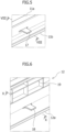
Figure 5 , thegate mark 17 of theupper frame 11 is located not on an outerperipheral portion 11a or an innerperipheral portion 11b of theupper frame 11 projecting toward the in-vehicle equipment, but between these portions. Molding thegarnish 10 using a submarine gate causes thegate mark 17 to be made at such a position. A distance of thegate mark 17 from the outerperipheral portion 11a and the innerperipheral portion 11b is preferably equal to or greater than 2 mm, more preferably equal to or greater than 4 mm. Thus, injection molding is performed using a PC/ABS resin from a gate opening at the position distant from the outerperipheral portion 11a and the innerperipheral portion 11b, which makes it possible to notably improve the impact resistance of thegarnish 10. - It is preferable that the
gate mark 17 be offset to the innerperipheral portion 11b with respect to a center between the outerperipheral portion 11a and the innerperipheral portion 11b of theupper frame 11. Thegate mark 17 may be a cause of a reduction in impact resistance. However, offsetting the gate mark to the innerperipheral portion 11b on the lower side makes thegarnish 10 unlikely to fracture, since if a person in the vehicle hits thegarnish 10 due to an accident or the like, it is supposed that the person is likely to hit an upper side of theupper frame 11. - The
gate mark 17 of theupper frame 11 has substantially a plate shape with a width direction thereof being along the longitudinal direction of thegarnish 10 and the shape is gradually flared toward theupper frame 11. Injection molding is performed using a gate opening providing thegate mark 17 in such a shape, which makes it possible to prevent the occurrence of a crack in thegarnish 10. - Likewise, as illustrated in
Figure 6 , thegate mark 18 of thelower frame 12 is located not on an outerperipheral portion 12a or an innerperipheral portion 12b of thelower frame 12 projecting toward the in-vehicle equipment, but between these portions by virtue of molding using the submarine gate. A distance of thegate mark 18 from the outerperipheral portion 12a and the innerperipheral portion 12b is preferably equal to or greater than 2 mm, more preferably equal to or greater than 4 mm. Thus, injection molding is performed using a PC/ABS resin from a gate opening at a position distant from the outerperipheral portion 12a and the innerperipheral portion 12b, which makes it possible to notably improve the impact resistance of thegarnish 10. - It is preferable that the
gate mark 18 be offset to the outerperipheral portion 12a with respect to a center between the outerperipheral portion 12a and the innerperipheral portion 12b of thelower frame 12. As described above, thegate mark 18 may be a cause of a reduction in impact resistance. However, providing the gate mark on the outerperipheral portion 12a on the lower side makes thegarnish 10 unlikely to fracture, since if a person in the vehicle hits thegarnish 10 due to an accident or the like, it is supposed that the person is likely to hit an upper side of thelower frame 11. - Likewise, the
gate mark 18 of thelower frame 12 also has substantially a plate shape with a width direction thereof being along the longitudinal direction of thegarnish 10 and the shape is gradually flared toward thelower frame 12. - Thus, the two gate marks 17, 18 exist in the
garnish 10. This is because thesingle garnish 10 is molded from the two gate openings by injection molding. Such injection molding using the two gate openings located at the gate marks 17, 18 causesweld lines garnish 10 as illustrated inFigure 7 . Such formation of theweld lines garnish 10 increases an angle at which the resins meet, thereby making it possible to improve an appearance of a portion corresponding to theweld lines - As illustrated in
Figure 8 , a height of thegate mark 17 of theupper frame 11 is higher than a height B of the innerperipheral portion 11b of the upper frame. By virtue of the height being higher than that of the innerperipheral portion 11b as described above, it is possible to automatically perform gate cutting at a timing when demolding of the injection molding is performed or, in a case in which nippers or the like are used to perform gate cutting, it is possible to secure a workspace for them. In addition, the height of thegate mark 17 of theupper frame 11 is lower than a height A of the outerperipheral portion 11a of the upper frame. By virtue of the height being lower than that of the outerperipheral portion 11a as described above, it is possible to secure a designed space on an in-vehicle-equipment side. - The formation of the
gate mark 17 is described with reference toFigure 9 . Thegarnish 10 is injection-molded using asubmarine gate 20. This makes it possible to place the gate opening of a mold (not illustrated) not in the projecting outerperipheral portion 11a and innerperipheral portion 11b of theupper frame 11, but at a portion therebetween. Thus, thegate mark 17a, which is higher than the outerperipheral portion 11a of the upper frame as illustrated inFigure 9 immediately after demolding, is able to be cut at a position C lower than the outerperipheral portion 11a of the upper frame with nippers or the like. Note that the gate mark may be automatically cut during demolding as described above. Note that thegate mark 18 of thelower frame 12 may be likewise formed and cut. - As illustrated in
Figure 10 , a height of thegate mark 18 of thelower frame 12 is higher than the height B of the innerperipheral portion 12b of the lower frame. By virtue of the height being higher than that of the innerperipheral portion 12b as described above, it is possible to automatically perform gate cutting at a timing when demolding of the injection molding is performed or, in a case in which nippers or the like are used to perform gate cutting, it is possible to secure a workspace for them. In addition, the height of thegate mark 18 of thelower frame 12 is lower than a height A of the outerperipheral portion 12a of the lower frame. By virtue of the height being lower than that of the outerperipheral portion 12a as described above, it is possible to secure a designed space on the in-vehicle-equipment side. - A plate molded article (180 mm x 250 mm x
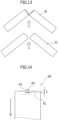
thickness 3 mm, a fine gate plate) of a PC/ABS resin (manufactured by Mitsubishi Engineering-Plastics Corporation, MB2215R) was produced by injection molding and strip specimens (10 mm x 70 mm xthickness 3 mm) in a resin flowing direction (an MD direction) and a vertical direction (a TD direction) were cut out of the plate molded article using an automatic sample molding machine.Figure 11 illustrates a spot at which the specimen in the TD direction was collected andFigure 12 illustrates a spot at which the specimen in the MD direction was collected. - As illustrated in
Figure 11 , a plate moldedarticle 30 is an article molded from a resin flowing in an arrow direction from a gate opening 32 of an injection molding machine. Astrip specimen 31 in the TD direction is a specimen cut such that a longitudinal direction of the strip specimen was vertical to the flow direction. A distance a from an end surface of the plate moldedarticle 30 on a side toward the gate opening 32 to a centerline of a first specimen (TD1) in the TD direction was 20 mm. In contrast, astrip specimen 41 in the MD direction is a specimen cut out of the plate moldedarticle 30 such that a longitudinal direction of thestrip specimen 41 was the same as the flowing direction indicated by an arrow as illustrated inFigure 12 . A distance b from a centerline of the plate moldedarticle 30 to a centerline of a first specimen (MD1) in the MD direction was 67.5 mm. - The specimens in the TD direction and the MD direction were each notched (R = 0.25) such that a remaining width was 8 mm. Then, a Charpy impact test was performed, and a Charpy impact value of each specimen was measured. Note that the Charpy impact test was performed using a Charpy impact tester (manufactured by Toyo Seiki Seisaku-sho, Ltd., model: IMPACT TESTER IT) in conformity with JIS K 7111. The test temperature was 23 °C and the hammer was 4J.
- As a result, all the
specimens 41 in the MD direction suffered partial fracture (P fracture) as illustrated inFigure 13 . Note that an arrow in the figure is a direction of hitting with a hammer during the Charpy impact test, which is an opposite direction to the resin flowing direction. In addition, Charpy impact values of the specimens (MD1 to MD10) in the MD direction were stably high values. No dependency on the specimen collection spot was observed. In contrast, it was observed that the specimens in the TD direction had a dependency on the specimen collection spot. The specimens (TD12 to TD14) in a portion in the vicinity of a flow end distant from the gate opening of injection molding suffered P fracture or hinge fracture (H fracture), whereas the specimen 31 (TD1 to TD11) in the TD direction close to a portion near the gate opening suffered complete fracture (C fracture) as illustrated inFigure 13 . Similarly, for the Charpy impact value, while being low near the gate opening and around a middle portion, the impact value increased with a reduction in distance to the flow end. With an assumption of an average of the Charpy impact values of the specimens in the MD direction being 100, even the highest value (TD14) among those of the specimens was merely 66, and an average thereof was 34, which was considerably low. - As described above, a specimen fracture morphology was different between the MD direction and the TD direction and the Charpy impact values of the specimens in the TD direction were equal to or less than a half of those of the specimens in the MD direction. Accordingly, molding a component with a high impact resistance from a PC/ABS resin requires measures for maintaining a high impact resistance value even in the TD direction.
- A Charpy impact value of each specimen in the MD direction and the TD direction was measured as in Test Example 1, except that a PC resin (manufactured by Mitsubishi Engineering-Plastics Corporation, S-3000R) was used in place of the PC/ABS resin.
- As a result, it was not observed that the PC resin had anisotropy depending on the resin flowing direction, as the PC/ABS resin in Test Example 1. As for the Charpy impact value of the PC resin, assuming that an average of the Charpy impact values of the specimens in the MD direction in Test Example 1 was 100, an average of the specimens in the MD direction was 142 and an average of the specimens in the TD direction was 144. All the specimens of the PC resin suffered P fracture. From this result, the anisotropy of the PC/ABS resin is thought to originate from an ABS resin and is speculated to be attributed to, in particular, an orientation of rubber in the ABS resin.
- With use of a submarine gate, a strip specimen in the TD direction with a gate opening placed in the specimen was produced and a Charpy impact test was performed. First, a plate molded article was molded using a submarine gate 62 (gate opening: 6 mm x 2.5 mm) such that a gate opening 63 of the
submarine gate 62 was placed inside with respect to an end surface of the plate moldedarticle 60 as illustrated inFigure 14 . Note that CK43-D4 manufactured by Techno-UMG Co., Ltd., was used as the PC/ABS resin. JSW180ton manufactured by The Japan Steel Works, Ltd., was used as the molding machine and a one-gate plate-shaped mold was used as the mold. A distance L between thegate opening 63 and the end surface of the plate molded article 60 (hereinafter, referred to as "gate distance") was changed by changing a shape of a PL surface (a mating surface of the mold) of a portion that is a loose piece (not illustrated). Thespecimen 61 was in the form of a strip specimen in the TD direction (80 mm x 10 mm xthickness 3 mm) as illustrated inFigure 14 and was cut out along the end surface of the plate moldedarticle 60. - Five of each of three types of specimens with gate distances L of 0 mm, 2 mm, and 4.4 mm were produced, and a Charpy impact test was performed using the Charpy impact tester in conformity with JIS K 7111 as in Test Examples 1 and 2. Note that no notch was made, and the hammer was 7.5 J in Test Example 3.
- In addition, for comparison, five strip specimens in the TD direction with
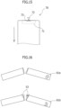
gate openings 73 placed on end portions ofspecimens 71 were produced using aside gate 72 as illustrated inFigure 15 and a Charpy impact test was performed under conditions similar to those described above. Table 1 shows a result for each specimen. Note that the Charpy impact values in Table 1, which are averages of measurement results of the five specimens of each type, are not measurement values (unit: KJ/m2), but are relative values, with an assumption that the average of the Charpy impact values of the specimens in the MD direction in Test Example 1 is 100. In addition, as for the specimens with the gate distances L of 0 mm and 2 mm molded using the submarine gate,Figure 16 illustrates observation results of fracture morphologies caused by the Charpy impact test. -
Table 1: Result of Charpy Impact Test of Test Example 3 Gate Shape Side Submarine Gate Distance L [mm] 0 0 2 4.4 Charpy Impact Value [Relative Value] 20 28 72 190 Fracture Morphology C C C C Plastic Deformation No No Yes Yes - As illustrated in
Figure 16 , specimens 50 with the gate distance L of 0 mm and specimens 52 with the gate distance L of 2 mm, which were molded using the submarine gate, all suffered complete fracture (C fracture). However, as for the specimens 50 with the gate distance L of 0 mm, almost no plastically deformed region was observed in a crack occurrence portion, and additionally, the impact resistance was low. In contrast, as for the specimens 52 with the gate distance L of 2 mm, aplastic deformation 53 was observed in a crack occurrence portion, and additionally, the impact resistance was more than twice as high as that of the specimens with the gate distance L of 0 mm as shown in Table 1. - Although not illustrated in
Figure 16 , a plastic deformation was observed also in crack occurrence portions of the specimens with the gate distance L of 4.4 mm and the impact resistance was notably high as shown in Table 1. In contrast, as for the specimens molded using the side gate (of course, the gate distance L was 0 mm), although not illustrated inFigure 16 , almost no plastically deformed region was observed in the crack occurrence portions, and additionally, the impact resistance was low as shown in Table 1. - From these results, it is presumed that a specimen molded using the submarine gate should be improved in impact resistance against a width-direction tensile deformation by virtue of the occurrence of a width-direction flow from the gate opening to the end of the specimen. An increase in gate distance is speculated to result in an increase in a region having a strong resistance against a width-direction deformation.
-
- 1
- Instrument panel
- 10
- Garnish
- 11
- Upper frame
- 12
- Lower frame
- 17, 18
- Gate mark
- 20a, 20b
- Weld line
- 30
- Plate molded article
- 31,41,61,71
- Specimen
Claims (6)
- A garnish for an instrument panel, the garnish being in a form of a frame configured to cover a periphery of in-vehicle equipment disposed around a middle of an instrument panel, the garnish comprising:an opening portion around a middle defined by an upper frame, a lower frame, and right and left frames of the garnish, whereinrespective outer peripheral portions and inner peripheral portions of the upper frame, the lower frame, and the right and left frames project toward the in-vehicle equipment,the garnish is formed of a polymer alloy of polycarbonate and acrylonitrile-butadiene-styrene (a PC/ABS resin), anda gate mark is provided on at least one of the upper frame, the lower frame, and the right and left frames between the outer peripheral portion and the inner peripheral portion, projecting toward the in-vehicle equipment.
- The garnish for an instrument panel as claimed in claim 1, wherein the gate mark has a shape gradually flared with respect to the frame.
- The garnish for an instrument panel as claimed in claim 1, wherein the gate mark has a height higher than the inner peripheral portion and lower than the outer peripheral portion of the frame.
- The garnish for an instrument panel as claimed in claim 1, wherein the gate mark is provided on the upper frame and offset to the inner peripheral portion with respect to a center between the outer peripheral portion and the inner peripheral portion of the upper frame.
- The garnish for an instrument panel as claimed in claim 1, wherein the gate mark is provided on the lower frame and is offset to the outer peripheral portion with respect to a center between the outer peripheral portion and the inner peripheral portion of the lower frame.
- The garnish for an instrument panel as claimed in claim 1, wherein a weld line is located at a corner.
Applications Claiming Priority (1)
| Application Number | Priority Date | Filing Date | Title |
|---|---|---|---|
| JP2022170678A JP2024062677A (en) | 2022-10-25 | 2022-10-25 | Instrument panel garnish |
Publications (2)
| Publication Number | Publication Date |
|---|---|
| EP4360957A1 true EP4360957A1 (en) | 2024-05-01 |
| EP4360957B1 EP4360957B1 (en) | 2025-03-12 |
Family
ID=87567380
Family Applications (1)
| Application Number | Title | Priority Date | Filing Date |
|---|---|---|---|
| EP23190925.0A Active EP4360957B1 (en) | 2022-10-25 | 2023-08-10 | Garnish for instrument panel |
Country Status (2)
| Country | Link |
|---|---|
| EP (1) | EP4360957B1 (en) |
| JP (1) | JP2024062677A (en) |
Citations (4)
| Publication number | Priority date | Publication date | Assignee | Title |
|---|---|---|---|---|
| JPH05201274A (en) | 1992-01-28 | 1993-08-10 | Suzuki Motor Corp | instrument panel |
| US20090284038A1 (en) * | 2008-05-14 | 2009-11-19 | Honda Motor Co., Ltd. | Instrument panel for vehicle and method for attaching vehicle-mounted device to instrument panel for vehicle |
| EP1801464B1 (en) * | 2005-12-23 | 2014-02-26 | Nissan Motor Manufacturing (UK) Ltd. | Gearshift finisher |
| JP6852422B2 (en) * | 2017-01-31 | 2021-03-31 | スズキ株式会社 | Front structure of the passenger compartment |
Family Cites Families (12)
| Publication number | Priority date | Publication date | Assignee | Title |
|---|---|---|---|---|
| JPH06183287A (en) * | 1992-12-21 | 1994-07-05 | Nissan Motor Co Ltd | Device mounting structure in instrument panel for vehicle |
| JPH0891097A (en) * | 1994-09-28 | 1996-04-09 | Suzuki Motor Corp | Mounting structure for resin molded parts in automobile instrument panel |
| JP2000062497A (en) * | 1998-08-25 | 2000-02-29 | Inoac Corp | Instrument panel |
| EP1445086A1 (en) * | 2001-09-18 | 2004-08-11 | Mitsubishi Jidosha Kogyo Kabushiki Kaisha | Resin product with flow pattern and method of manufacturing the resin product |
| JP2008068633A (en) * | 2007-12-06 | 2008-03-27 | Dainippon Printing Co Ltd | Injection mold |
| JP2010253721A (en) * | 2009-04-22 | 2010-11-11 | Sumitomo Chemical Co Ltd | Injection mold and molded body |
| WO2014129483A1 (en) * | 2013-02-19 | 2014-08-28 | 三菱エンジニアリングプラスチックス株式会社 | Aromatic polycarbonate resin molded body and panel |
| JP2015096327A (en) * | 2013-10-08 | 2015-05-21 | 三菱エンジニアリングプラスチックス株式会社 | Multicolor molded product |
| JP6314703B2 (en) * | 2014-07-02 | 2018-04-25 | 三菱エンジニアリングプラスチックス株式会社 | Multicolor molded product and molding method thereof |
| JP6941295B2 (en) * | 2017-09-19 | 2021-09-29 | いすゞ自動車株式会社 | Center cluster panel mounting structure |
| JP7201500B2 (en) * | 2019-03-22 | 2023-01-10 | ダイキョーニシカワ株式会社 | Decorative part for vehicle, two-color mold and two-color injection molding method |
| JP7235560B2 (en) * | 2019-03-28 | 2023-03-08 | 株式会社カナック企画 | A mounting device for replacing a small-screen car navigation system installed in an automobile with a large-screen car navigation system |
-
2022
- 2022-10-25 JP JP2022170678A patent/JP2024062677A/en active Pending
-
2023
- 2023-08-10 EP EP23190925.0A patent/EP4360957B1/en active Active
Patent Citations (4)
| Publication number | Priority date | Publication date | Assignee | Title |
|---|---|---|---|---|
| JPH05201274A (en) | 1992-01-28 | 1993-08-10 | Suzuki Motor Corp | instrument panel |
| EP1801464B1 (en) * | 2005-12-23 | 2014-02-26 | Nissan Motor Manufacturing (UK) Ltd. | Gearshift finisher |
| US20090284038A1 (en) * | 2008-05-14 | 2009-11-19 | Honda Motor Co., Ltd. | Instrument panel for vehicle and method for attaching vehicle-mounted device to instrument panel for vehicle |
| JP6852422B2 (en) * | 2017-01-31 | 2021-03-31 | スズキ株式会社 | Front structure of the passenger compartment |
Also Published As
| Publication number | Publication date |
|---|---|
| JP2024062677A (en) | 2024-05-10 |
| EP4360957B1 (en) | 2025-03-12 |
Similar Documents
| Publication | Publication Date | Title |
|---|---|---|
| US9156428B2 (en) | Vehicle safety device | |
| EP0465317B1 (en) | Injection-molded article | |
| KR100341441B1 (en) | Car interior mamber and molding method of the same | |
| US11198477B2 (en) | Opening panel made from plastic, which continues to block the opening in the body shell in the event of an impact | |
| US20240034413A1 (en) | Dashboard crossbeam assembly for a vehicle | |
| KR20050009700A (en) | Resinous interior member of opening/closing body, mold therefor and method of molding the same | |
| US6857681B2 (en) | Connecting structure of air duct of vehicular air conditioning unit | |
| CN101384457A (en) | Airbag guide with a covering | |
| US20130001929A1 (en) | Air bag chute topper system | |
| US9403507B2 (en) | Vehicular interior member assembly and vehicular interior part | |
| EP4360957A1 (en) | Garnish for instrument panel | |
| US10603986B2 (en) | Structure of wing-knob for air vent | |
| US10737638B2 (en) | Vehicular pillar structure | |
| US9327656B2 (en) | Vehicle interior material | |
| US10676136B2 (en) | Cross-car beam | |
| JP2775146B2 (en) | Shock absorbing structure for vehicles | |
| US10207570B2 (en) | Vehicle rear portion structure | |
| US20200172169A1 (en) | Front pillar structure | |
| US20100045005A1 (en) | Three door air bag chute | |
| US20220410842A1 (en) | Side defroster air outlet structure | |
| JP2025076712A (en) | PC/ABS resin and automobile interior parts formed therefrom | |
| JP3689676B2 (en) | Plastic molded product | |
| CN224197573U (en) | Water-cutting structure, door assembly and vehicle | |
| JPH0939610A (en) | Front differential structure for automobile | |
| EP3889011B1 (en) | Front vehicle-body structure for a vehicle, vehicle body structure, and vehicle |
Legal Events
| Date | Code | Title | Description |
|---|---|---|---|
| PUAI | Public reference made under article 153(3) epc to a published international application that has entered the european phase |
Free format text: ORIGINAL CODE: 0009012 |
|
| STAA | Information on the status of an ep patent application or granted ep patent |
Free format text: STATUS: REQUEST FOR EXAMINATION WAS MADE |
|
| 17P | Request for examination filed |
Effective date: 20230810 |
|
| AK | Designated contracting states |
Kind code of ref document: A1 Designated state(s): AL AT BE BG CH CY CZ DE DK EE ES FI FR GB GR HR HU IE IS IT LI LT LU LV MC ME MK MT NL NO PL PT RO RS SE SI SK SM TR |
|
| GRAP | Despatch of communication of intention to grant a patent |
Free format text: ORIGINAL CODE: EPIDOSNIGR1 |
|
| STAA | Information on the status of an ep patent application or granted ep patent |
Free format text: STATUS: GRANT OF PATENT IS INTENDED |
|
| RIC1 | Information provided on ipc code assigned before grant |
Ipc: B60R 11/00 20060101ALN20241106BHEP Ipc: B60R 13/02 20060101ALI20241106BHEP Ipc: B60R 11/02 20060101AFI20241106BHEP |
|
| RIC1 | Information provided on ipc code assigned before grant |
Ipc: B60R 11/00 20060101ALN20241121BHEP Ipc: B60R 13/02 20060101ALI20241121BHEP Ipc: B60R 11/02 20060101AFI20241121BHEP |
|
| INTG | Intention to grant announced |
Effective date: 20241206 |
|
| RIN1 | Information on inventor provided before grant (corrected) |
Inventor name: IWAMOTO, KAZUHITO Inventor name: IWASAKI, TAKUYA |
|
| GRAS | Grant fee paid |
Free format text: ORIGINAL CODE: EPIDOSNIGR3 |
|
| GRAA | (expected) grant |
Free format text: ORIGINAL CODE: 0009210 |
|
| STAA | Information on the status of an ep patent application or granted ep patent |
Free format text: STATUS: THE PATENT HAS BEEN GRANTED |
|
| AK | Designated contracting states |
Kind code of ref document: B1 Designated state(s): AL AT BE BG CH CY CZ DE DK EE ES FI FR GB GR HR HU IE IS IT LI LT LU LV MC ME MK MT NL NO PL PT RO RS SE SI SK SM TR |
|
| REG | Reference to a national code |
Ref country code: GB Ref legal event code: FG4D |
|
| REG | Reference to a national code |
Ref country code: CH Ref legal event code: EP |
|
| REG | Reference to a national code |
Ref country code: DE Ref legal event code: R096 Ref document number: 602023002390 Country of ref document: DE |
|
| REG | Reference to a national code |
Ref country code: IE Ref legal event code: FG4D |
|
| PG25 | Lapsed in a contracting state [announced via postgrant information from national office to epo] |
Ref country code: RS Free format text: LAPSE BECAUSE OF FAILURE TO SUBMIT A TRANSLATION OF THE DESCRIPTION OR TO PAY THE FEE WITHIN THE PRESCRIBED TIME-LIMIT Effective date: 20250612 |
|
| PG25 | Lapsed in a contracting state [announced via postgrant information from national office to epo] |
Ref country code: FI Free format text: LAPSE BECAUSE OF FAILURE TO SUBMIT A TRANSLATION OF THE DESCRIPTION OR TO PAY THE FEE WITHIN THE PRESCRIBED TIME-LIMIT Effective date: 20250312 |
|
| PG25 | Lapsed in a contracting state [announced via postgrant information from national office to epo] |
Ref country code: ES Free format text: LAPSE BECAUSE OF FAILURE TO SUBMIT A TRANSLATION OF THE DESCRIPTION OR TO PAY THE FEE WITHIN THE PRESCRIBED TIME-LIMIT Effective date: 20250312 |
|
| REG | Reference to a national code |
Ref country code: LT Ref legal event code: MG9D |
|
| PG25 | Lapsed in a contracting state [announced via postgrant information from national office to epo] |
Ref country code: NO Free format text: LAPSE BECAUSE OF FAILURE TO SUBMIT A TRANSLATION OF THE DESCRIPTION OR TO PAY THE FEE WITHIN THE PRESCRIBED TIME-LIMIT Effective date: 20250612 |
|
| PG25 | Lapsed in a contracting state [announced via postgrant information from national office to epo] |
Ref country code: HR Free format text: LAPSE BECAUSE OF FAILURE TO SUBMIT A TRANSLATION OF THE DESCRIPTION OR TO PAY THE FEE WITHIN THE PRESCRIBED TIME-LIMIT Effective date: 20250312 |
|
| REG | Reference to a national code |
Ref country code: NL Ref legal event code: MP Effective date: 20250312 |
|
| PG25 | Lapsed in a contracting state [announced via postgrant information from national office to epo] |
Ref country code: LV Free format text: LAPSE BECAUSE OF FAILURE TO SUBMIT A TRANSLATION OF THE DESCRIPTION OR TO PAY THE FEE WITHIN THE PRESCRIBED TIME-LIMIT Effective date: 20250312 |
|
| PGFP | Annual fee paid to national office [announced via postgrant information from national office to epo] |
Ref country code: FR Payment date: 20250617 Year of fee payment: 3 |
|
| PG25 | Lapsed in a contracting state [announced via postgrant information from national office to epo] |
Ref country code: GR Free format text: LAPSE BECAUSE OF FAILURE TO SUBMIT A TRANSLATION OF THE DESCRIPTION OR TO PAY THE FEE WITHIN THE PRESCRIBED TIME-LIMIT Effective date: 20250613 Ref country code: BG Free format text: LAPSE BECAUSE OF FAILURE TO SUBMIT A TRANSLATION OF THE DESCRIPTION OR TO PAY THE FEE WITHIN THE PRESCRIBED TIME-LIMIT Effective date: 20250312 |
|
| PG25 | Lapsed in a contracting state [announced via postgrant information from national office to epo] |
Ref country code: NL Free format text: LAPSE BECAUSE OF FAILURE TO SUBMIT A TRANSLATION OF THE DESCRIPTION OR TO PAY THE FEE WITHIN THE PRESCRIBED TIME-LIMIT Effective date: 20250312 |
|
| PG25 | Lapsed in a contracting state [announced via postgrant information from national office to epo] |
Ref country code: SE Free format text: LAPSE BECAUSE OF FAILURE TO SUBMIT A TRANSLATION OF THE DESCRIPTION OR TO PAY THE FEE WITHIN THE PRESCRIBED TIME-LIMIT Effective date: 20250312 |
|
| PG25 | Lapsed in a contracting state [announced via postgrant information from national office to epo] |
Ref country code: SM Free format text: LAPSE BECAUSE OF FAILURE TO SUBMIT A TRANSLATION OF THE DESCRIPTION OR TO PAY THE FEE WITHIN THE PRESCRIBED TIME-LIMIT Effective date: 20250312 |
|
| PG25 | Lapsed in a contracting state [announced via postgrant information from national office to epo] |
Ref country code: PT Free format text: LAPSE BECAUSE OF FAILURE TO SUBMIT A TRANSLATION OF THE DESCRIPTION OR TO PAY THE FEE WITHIN THE PRESCRIBED TIME-LIMIT Effective date: 20250714 |
|
| PGFP | Annual fee paid to national office [announced via postgrant information from national office to epo] |
Ref country code: DE Payment date: 20250812 Year of fee payment: 3 |
|
| PG25 | Lapsed in a contracting state [announced via postgrant information from national office to epo] |
Ref country code: IT Free format text: LAPSE BECAUSE OF FAILURE TO SUBMIT A TRANSLATION OF THE DESCRIPTION OR TO PAY THE FEE WITHIN THE PRESCRIBED TIME-LIMIT Effective date: 20250312 Ref country code: PL Free format text: LAPSE BECAUSE OF FAILURE TO SUBMIT A TRANSLATION OF THE DESCRIPTION OR TO PAY THE FEE WITHIN THE PRESCRIBED TIME-LIMIT Effective date: 20250312 |
|
| PG25 | Lapsed in a contracting state [announced via postgrant information from national office to epo] |
Ref country code: AT Free format text: LAPSE BECAUSE OF FAILURE TO SUBMIT A TRANSLATION OF THE DESCRIPTION OR TO PAY THE FEE WITHIN THE PRESCRIBED TIME-LIMIT Effective date: 20250312 |
|
| PG25 | Lapsed in a contracting state [announced via postgrant information from national office to epo] |
Ref country code: EE Free format text: LAPSE BECAUSE OF FAILURE TO SUBMIT A TRANSLATION OF THE DESCRIPTION OR TO PAY THE FEE WITHIN THE PRESCRIBED TIME-LIMIT Effective date: 20250312 Ref country code: CZ Free format text: LAPSE BECAUSE OF FAILURE TO SUBMIT A TRANSLATION OF THE DESCRIPTION OR TO PAY THE FEE WITHIN THE PRESCRIBED TIME-LIMIT Effective date: 20250312 |
|
| PG25 | Lapsed in a contracting state [announced via postgrant information from national office to epo] |
Ref country code: RO Free format text: LAPSE BECAUSE OF FAILURE TO SUBMIT A TRANSLATION OF THE DESCRIPTION OR TO PAY THE FEE WITHIN THE PRESCRIBED TIME-LIMIT Effective date: 20250312 |
|
| PG25 | Lapsed in a contracting state [announced via postgrant information from national office to epo] |
Ref country code: SK Free format text: LAPSE BECAUSE OF FAILURE TO SUBMIT A TRANSLATION OF THE DESCRIPTION OR TO PAY THE FEE WITHIN THE PRESCRIBED TIME-LIMIT Effective date: 20250312 |
|
| PG25 | Lapsed in a contracting state [announced via postgrant information from national office to epo] |
Ref country code: IS Free format text: LAPSE BECAUSE OF FAILURE TO SUBMIT A TRANSLATION OF THE DESCRIPTION OR TO PAY THE FEE WITHIN THE PRESCRIBED TIME-LIMIT Effective date: 20250712 |
|
| REG | Reference to a national code |
Ref country code: DE Ref legal event code: R097 Ref document number: 602023002390 Country of ref document: DE |
|
| PG25 | Lapsed in a contracting state [announced via postgrant information from national office to epo] |
Ref country code: DK Free format text: LAPSE BECAUSE OF FAILURE TO SUBMIT A TRANSLATION OF THE DESCRIPTION OR TO PAY THE FEE WITHIN THE PRESCRIBED TIME-LIMIT Effective date: 20250312 |
|
| PLBE | No opposition filed within time limit |
Free format text: ORIGINAL CODE: 0009261 |
|
| STAA | Information on the status of an ep patent application or granted ep patent |
Free format text: STATUS: NO OPPOSITION FILED WITHIN TIME LIMIT |
|
| REG | Reference to a national code |
Ref country code: CH Ref legal event code: L10 Free format text: ST27 STATUS EVENT CODE: U-0-0-L10-L00 (AS PROVIDED BY THE NATIONAL OFFICE) Effective date: 20260121 |
|
| 26N | No opposition filed |
Effective date: 20251215 |
|
| PG25 | Lapsed in a contracting state [announced via postgrant information from national office to epo] |
Ref country code: MC Free format text: LAPSE BECAUSE OF FAILURE TO SUBMIT A TRANSLATION OF THE DESCRIPTION OR TO PAY THE FEE WITHIN THE PRESCRIBED TIME-LIMIT Effective date: 20250312 |
|
| PG25 | Lapsed in a contracting state [announced via postgrant information from national office to epo] |
Ref country code: LU Free format text: LAPSE BECAUSE OF NON-PAYMENT OF DUE FEES Effective date: 20250810 |