EP4360524A1 - Bodenreiniger mit beweglich gelagertem saugmund - Google Patents
Bodenreiniger mit beweglich gelagertem saugmund Download PDFInfo
- Publication number
- EP4360524A1 EP4360524A1 EP23201169.2A EP23201169A EP4360524A1 EP 4360524 A1 EP4360524 A1 EP 4360524A1 EP 23201169 A EP23201169 A EP 23201169A EP 4360524 A1 EP4360524 A1 EP 4360524A1
- Authority
- EP
- European Patent Office
- Prior art keywords
- suction mouth
- floor
- chassis
- vacuum cleaner
- floor surface
- Prior art date
- Legal status (The legal status is an assumption and is not a legal conclusion. Google has not performed a legal analysis and makes no representation as to the accuracy of the status listed.)
- Granted
Links
Images



Classifications
-
- A—HUMAN NECESSITIES
- A47—FURNITURE; DOMESTIC ARTICLES OR APPLIANCES; COFFEE MILLS; SPICE MILLS; SUCTION CLEANERS IN GENERAL
- A47L—DOMESTIC WASHING OR CLEANING; SUCTION CLEANERS IN GENERAL
- A47L9/00—Details or accessories of suction cleaners, e.g. mechanical means for controlling the suction or for effecting pulsating action; Storing devices specially adapted to suction cleaners or parts thereof; Carrying-vehicles specially adapted for suction cleaners
- A47L9/02—Nozzles
- A47L9/04—Nozzles with driven brushes or agitators
- A47L9/0405—Driving means for the brushes or agitators
- A47L9/0411—Driving means for the brushes or agitators driven by electric motor
-
- A—HUMAN NECESSITIES
- A47—FURNITURE; DOMESTIC ARTICLES OR APPLIANCES; COFFEE MILLS; SPICE MILLS; SUCTION CLEANERS IN GENERAL
- A47L—DOMESTIC WASHING OR CLEANING; SUCTION CLEANERS IN GENERAL
- A47L9/00—Details or accessories of suction cleaners, e.g. mechanical means for controlling the suction or for effecting pulsating action; Storing devices specially adapted to suction cleaners or parts thereof; Carrying-vehicles specially adapted for suction cleaners
- A47L9/02—Nozzles
- A47L9/06—Nozzles with fixed, e.g. adjustably fixed brushes or the like
- A47L9/066—Nozzles with fixed, e.g. adjustably fixed brushes or the like with adjustably mounted brushes, combs, lips or pads; Height adjustment of nozzle or dust loosening tools
-
- A—HUMAN NECESSITIES
- A46—BRUSHWARE
- A46B—BRUSHES
- A46B13/00—Brushes with driven brush bodies or carriers
- A46B13/001—Cylindrical or annular brush bodies
-
- A—HUMAN NECESSITIES
- A46—BRUSHWARE
- A46B—BRUSHES
- A46B13/00—Brushes with driven brush bodies or carriers
- A46B13/02—Brushes with driven brush bodies or carriers power-driven carriers
-
- A—HUMAN NECESSITIES
- A46—BRUSHWARE
- A46B—BRUSHES
- A46B9/00—Arrangements of the bristles in the brush body
- A46B9/02—Position or arrangement of bristles in relation to surface of the brush body, e.g. inclined, in rows, in groups
- A46B9/025—Position or arrangement of bristles in relation to surface of the brush body, e.g. inclined, in rows, in groups the bristles or the tufts being arranged in an angled position relative to each other
-
- A—HUMAN NECESSITIES
- A46—BRUSHWARE
- A46B—BRUSHES
- A46B9/00—Arrangements of the bristles in the brush body
- A46B9/02—Position or arrangement of bristles in relation to surface of the brush body, e.g. inclined, in rows, in groups
- A46B9/026—Position or arrangement of bristles in relation to surface of the brush body, e.g. inclined, in rows, in groups where the surface of the brush body or carrier is not in one plane, e.g. not flat
-
- A—HUMAN NECESSITIES
- A47—FURNITURE; DOMESTIC ARTICLES OR APPLIANCES; COFFEE MILLS; SPICE MILLS; SUCTION CLEANERS IN GENERAL
- A47L—DOMESTIC WASHING OR CLEANING; SUCTION CLEANERS IN GENERAL
- A47L9/00—Details or accessories of suction cleaners, e.g. mechanical means for controlling the suction or for effecting pulsating action; Storing devices specially adapted to suction cleaners or parts thereof; Carrying-vehicles specially adapted for suction cleaners
- A47L9/0072—Mechanical means for controlling the suction or for effecting pulsating action
-
- A—HUMAN NECESSITIES
- A47—FURNITURE; DOMESTIC ARTICLES OR APPLIANCES; COFFEE MILLS; SPICE MILLS; SUCTION CLEANERS IN GENERAL
- A47L—DOMESTIC WASHING OR CLEANING; SUCTION CLEANERS IN GENERAL
- A47L9/00—Details or accessories of suction cleaners, e.g. mechanical means for controlling the suction or for effecting pulsating action; Storing devices specially adapted to suction cleaners or parts thereof; Carrying-vehicles specially adapted for suction cleaners
- A47L9/009—Carrying-vehicles; Arrangements of trollies or wheels; Means for avoiding mechanical obstacles
-
- A—HUMAN NECESSITIES
- A47—FURNITURE; DOMESTIC ARTICLES OR APPLIANCES; COFFEE MILLS; SPICE MILLS; SUCTION CLEANERS IN GENERAL
- A47L—DOMESTIC WASHING OR CLEANING; SUCTION CLEANERS IN GENERAL
- A47L9/00—Details or accessories of suction cleaners, e.g. mechanical means for controlling the suction or for effecting pulsating action; Storing devices specially adapted to suction cleaners or parts thereof; Carrying-vehicles specially adapted for suction cleaners
- A47L9/02—Nozzles
- A47L9/04—Nozzles with driven brushes or agitators
- A47L9/0455—Bearing means therefor
-
- A—HUMAN NECESSITIES
- A47—FURNITURE; DOMESTIC ARTICLES OR APPLIANCES; COFFEE MILLS; SPICE MILLS; SUCTION CLEANERS IN GENERAL
- A47L—DOMESTIC WASHING OR CLEANING; SUCTION CLEANERS IN GENERAL
- A47L9/00—Details or accessories of suction cleaners, e.g. mechanical means for controlling the suction or for effecting pulsating action; Storing devices specially adapted to suction cleaners or parts thereof; Carrying-vehicles specially adapted for suction cleaners
- A47L9/02—Nozzles
- A47L9/04—Nozzles with driven brushes or agitators
- A47L9/0461—Dust-loosening tools, e.g. agitators, brushes
- A47L9/0466—Rotating tools
- A47L9/0477—Rolls
-
- A—HUMAN NECESSITIES
- A47—FURNITURE; DOMESTIC ARTICLES OR APPLIANCES; COFFEE MILLS; SPICE MILLS; SUCTION CLEANERS IN GENERAL
- A47L—DOMESTIC WASHING OR CLEANING; SUCTION CLEANERS IN GENERAL
- A47L9/00—Details or accessories of suction cleaners, e.g. mechanical means for controlling the suction or for effecting pulsating action; Storing devices specially adapted to suction cleaners or parts thereof; Carrying-vehicles specially adapted for suction cleaners
- A47L9/02—Nozzles
- A47L9/04—Nozzles with driven brushes or agitators
- A47L9/0494—Height adjustment of dust-loosening tools
-
- A—HUMAN NECESSITIES
- A47—FURNITURE; DOMESTIC ARTICLES OR APPLIANCES; COFFEE MILLS; SPICE MILLS; SUCTION CLEANERS IN GENERAL
- A47L—DOMESTIC WASHING OR CLEANING; SUCTION CLEANERS IN GENERAL
- A47L9/00—Details or accessories of suction cleaners, e.g. mechanical means for controlling the suction or for effecting pulsating action; Storing devices specially adapted to suction cleaners or parts thereof; Carrying-vehicles specially adapted for suction cleaners
- A47L9/02—Nozzles
- A47L9/06—Nozzles with fixed, e.g. adjustably fixed brushes or the like
- A47L9/0606—Nozzles with fixed, e.g. adjustably fixed brushes or the like rigidly anchored brushes, combs, lips or pads
- A47L9/0626—Rigidly anchored lips, e.g. nozzles adapted for picking up liquids
-
- A—HUMAN NECESSITIES
- A47—FURNITURE; DOMESTIC ARTICLES OR APPLIANCES; COFFEE MILLS; SPICE MILLS; SUCTION CLEANERS IN GENERAL
- A47L—DOMESTIC WASHING OR CLEANING; SUCTION CLEANERS IN GENERAL
- A47L9/00—Details or accessories of suction cleaners, e.g. mechanical means for controlling the suction or for effecting pulsating action; Storing devices specially adapted to suction cleaners or parts thereof; Carrying-vehicles specially adapted for suction cleaners
- A47L9/02—Nozzles
- A47L9/06—Nozzles with fixed, e.g. adjustably fixed brushes or the like
- A47L9/0666—Nozzles with fixed, e.g. adjustably fixed brushes or the like with tilting, floating or similarly arranged brushes, combs, lips or pads
-
- A—HUMAN NECESSITIES
- A46—BRUSHWARE
- A46B—BRUSHES
- A46B2200/00—Brushes characterized by their functions, uses or applications
- A46B2200/30—Brushes for cleaning or polishing
- A46B2200/3033—Household brush, i.e. brushes for cleaning in the house or dishes
-
- A—HUMAN NECESSITIES
- A47—FURNITURE; DOMESTIC ARTICLES OR APPLIANCES; COFFEE MILLS; SPICE MILLS; SUCTION CLEANERS IN GENERAL
- A47L—DOMESTIC WASHING OR CLEANING; SUCTION CLEANERS IN GENERAL
- A47L2201/00—Robotic cleaning machines, i.e. with automatic control of the travelling movement or the cleaning operation
Definitions
- the invention relates to an automatic floor cleaner with a suction device.
- the invention relates to the mounting of the suction mouth relative to a chassis of the floor cleaner.
- a floor vacuum cleaner is designed to move across a floor surface and clean it.
- the floor vacuum cleaner includes a suction unit that creates an air flow through a suction mouth that is attached to a chassis of the floor vacuum cleaner.
- the suction mouth should be at a predetermined distance from the floor surface so as not to impede the horizontal entry of coarse dirt or foreign bodies. However, the distance should not be too great either in order to be able to use the air flow efficiently to pick up dirt.
- the suction mouth is rigidly attached to the chassis, it can run into an obstacle and hinder the movement of the floor vacuum. If the suction mouth is arranged to be vertically movable, the distance to the floor surface can temporarily be too small or too large, for example when driving over an edge or threshold.
- Various suggestions have been made for the movable mounting of a suction mouth in relation to a chassis.
- DE 10 2010 000 577 A1 relates to a floor vacuum cleaner with a suction mouth that is pivotally mounted at a rear end with respect to the direction of travel.
- a guide consisting of a guide and a guide block is provided at a front end to allow vertical movement.
- the front end on the chassis is pressed towards the floor surface by means of a coil spring. This can prevent coarse material from being picked up in the area of the suction mouth.
- One object underlying the present invention is to provide an improved technology for the flexible connection of a suction mouth to a floor vacuum cleaner.
- the invention solves this problem by means of the subject matter of the independent claims. Subclaims give preferred embodiments.
- a floor vacuum cleaner for cleaning a floor surface comprises a chassis with a chassis for traveling on the floor surface; and a suction mouth for admitting an air flow in the area of the floor surface, wherein the suction mouth is mounted relative to the chassis at the front left and right in the direction of travel by means of an arrangement of a pin and a guide in such a way that tilting of the suction mouth about the pins, rotation of the suction mouth about a longitudinal axis and vertical movement of the suction mouth are possible, but movement of the suction mouth in the longitudinal direction of the chassis is prevented.
- This mounting allows the suction mouth to be held in an advantageous position relative to the ground.
- the suction mouth can still be held in such a way that dirt is effectively picked up from the floor surface.
- the suction mouth can be guided along the ground more effectively when driving over a threshold or step, a transition between different floor coverings, a cable, a joint or another obstacle. It can be movable in three predetermined degrees of freedom, with a first degree of freedom involving tilting the suction mouth around a transverse axis of the floor vacuum, a second degree of freedom involving pivoting around a longitudinal axis and a third degree of freedom involving displacement along a vertical axis.
- the suction mouth can also be moved along a transverse axis of the chassis.
- a displacement from a predetermined position can be counteracted by an elastic element.
- the restoring forces of the elastic element for a displacement to the left and to the right can be the same or different.
- An arrangement with two different elastic elements can be used for this.
- the displacement can be limited to a predetermined path on one or both sides.
- the combination of the degrees of freedom described allows coarse dirt to enter the area of the suction mouth from the floor surface and be sucked in more easily.
- the floor vacuum cleaner can avoid getting stuck on an edge or digging into a soft or long-pile surface.
- a pin is provided on the suction mouth and a guide on the Chassis. This can improve vertical guidance of the pin.
- the pins extend along a common axis and can be designed like shield pins on both sides of the suction mouth.
- the receptacle can be formed by two mutually parallel contact surfaces, each of which extends perpendicular to the longitudinal axis of the chassis.
- a contact surface can be as narrow as desired; in one embodiment, for example, a vertical cylinder can form the contact surface.
- An inverted arrangement in which a pin is provided on the chassis and a receptacle is provided on the suction mouth, can also be used.
- the suction mouth is mounted so that it can move vertically at the rear left and right. A separate guide in this area is not required. The mobility of the suction mouth can thus be comprehensively defined.
- a vertical position of the suction mouth at the rear end is defined by the weight of the suction mouth or a component connected thereto.
- an elastic element can be provided which is designed to press a rear end of the suction mouth into a predetermined vertical position relative to the chassis.
- An elastic element can be provided at each of the rear left and rear right ends.
- An elastic element can act both upwards and downwards, whereby effective spring constants can be the same or different.
- An elastic element can be dispensed with at the front end; here the vertical position can preferably be adjusted based on the weight of the suction mouth or in extension of the rear end.
- the elastic element can be formed by an elastic pipe socket through which the air flow flows from the suction mouth in the direction of the suction system.
- the pipe socket is preferably located at the suction mouth at the rear in the direction of travel and runs approximately horizontally.
- the elasticity of the pipe socket can be used to position the suction mouth and help to save a separate elastic element.
- the pipe socket can be designed in such a way that it provides predetermined elastic forces against a rotation about a longitudinal axis (second degree of freedom) and a vertical deflection of the suction mouth (third degree of freedom). These forces can be limited within certain limits by the shape and material selection of the suction socket. be determined independently of each other.
- a deflection of a rear end of the suction mouth from the predetermined position upwards and/or downwards is limited to a predetermined path.
- An upward deflection path can be greater than a downward deflection path.
- the suction mouth can be deflected relative to the chassis by approximately 4.5 mm upwards and approximately 2.3 mm downwards before a stop limits the movement.
- An upward deflection of the front end of the suction mouth can be limited to a further predetermined value.
- This deflection path can be less than an upward or downward deflection path of the rear end.
- the front end can be deflected upwards by approximately 1 - 2 mm.
- a downward deflection can be not provided or can be zero.
- a brush roller with a rotation axis running transversely to the direction of travel is preferably mounted in the suction mouth.
- the brush roller can be rotated about the rotation axis by means of a drive motor and is designed to remove dirt from the floor surface or to guide it in the area of the suction mouth.
- Contact between the brush roller and the surface can be improved by the proposed floating mounting of the suction mouth, so that cleaning of the floor surface using the brush roller can be improved.
- a sealing lip can be provided in the area of a rear end of the suction mouth.
- the sealing lip preferably extends in the transverse direction and is designed to lie as close to the floor surface as possible and to seal the suction mouth from the floor surface.
- the sealing lip is preferably made of an elastic material so that it can be elastically deformed if necessary on an obstacle or an unevenness on the floor surface.
- a sealing effect of the sealing lip against the floor surface can be further improved by the described mobility of the suction mouth with respect to the chassis.
- a sliding element can be provided to support a rear end of the suction mouth against the floor surface.
- the sliding element can have a surface made of plastic or textile (thread lifter). If a sealing lip is provided, the sliding element is located behind the sealing lip with respect to the direction of travel.
- the chassis can comprise a drive wheel and a control device to control a movement of the floor vacuum on the floor surface.
- the floor vacuum is preferably intended for autonomous processing of a floor surface.
- the floor surface is further preferably comprised of a household and can, for example, relate to one or more rooms.
- FIG. 1 shows an exemplary floor vacuum 100.
- the floor vacuum 100 comprises a chassis 105 with a running gear 110, which is designed to support the chassis 105 against a floor surface 115.
- the running gear 110 preferably comprises at least one drive wheel, which can be driven by means of a drive motor.
- a control device for controlling the drive motor and/or a steering system can be provided.
- the control device is preferably designed to control an autonomous movement of the floor vacuum 100 on the floor surface 115.
- the floor vacuum 100 can be controlled to travel over a predetermined section of the floor surface 115 and to process it in the process.
- a suction mouth 120 For processing the floor surface 115, a suction mouth 120 is provided, in which a brush roller 125 with a horizontal axis of rotation is arranged.
- the suction mouth 120 is connected via a pipe socket 130 to a suction unit 135, which is preferably arranged behind the suction mouth 105 with respect to a direction of travel 140.
- the suction unit 135 is in Figure 1 not directly visible and is located in the filter housing shown.
- the suction mouth 120 forms a chamber with a rear opening which is connected to the pipe socket 130 and a lower opening through which a section of the brush roller 125 can protrude and through which an air flow can enter.
- the brush roller 125 can be driven about the axis of rotation by means of a drive motor (not shown) in order to mechanically treat the floor surface 115.
- the suction mouth 120 is movable relative to the chassis 105 and can be pressed into a predetermined position relative to it by means of its own weight or by means of an elastic element. Edges on the underside of the suction mouth 120 are preferably rounded or chamfered in order to better deflect the suction mouth 120 upwards when it comes into contact with an obstacle on the floor surface 115.
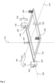
- FIG. 2 shows a schematic representation of the bearing of the suction mouth 120 on the chassis 105.
- the suction mouth 120 is shown in a simplified manner as a frame and the chassis 105 is shown in a simplified manner as two bearing points.
- a transverse axis 205, a longitudinal axis 210 and a vertical axis 215 are defined, which preferably form a right-hand system.
- the suction mouth 120 can be tilted about the transverse axis 205, which corresponds to a first degree of freedom 225.
- the suction mouth 120 can be pivoted about the longitudinal axis 210, which corresponds to a second degree of freedom 230.
- the suction mouth 120 can be displaced along the vertical axis 215, which corresponds to a third degree of freedom 235. Movements of the suction mouth in the degrees of freedom 225 to 235 can be coupled to one another in a predetermined manner.
- a movement along the transverse axis 205 is in the illustrated embodiment by lateral distances between the suction mouth 120 and the bearing points on a predetermined path.
- An elastic element can cause a return to a predetermined position when the suction mouth 120 is deflected horizontally.
- the elastic element can be assigned to this movement. In another embodiment, this movement is prevented, for example by the distances mentioned being close to zero.
- the suction mouth 120 is preferably immobile along the longitudinal axis 210.
- a rotation about the vertical axis 215 is preferably also prevented. Overall, the suction mouth 120 is thus movable in 4 or 3 degrees of freedom and immobile in the remaining 2 or 3 degrees of freedom.
- a pin 240 is attached to the suction mouth 120 at the front left and right with respect to the direction of travel 140, with the pins 240 extending along a common axis of rotation.
- the pins 240 are part of a continuous axis; in another embodiment, the axis can also be interrupted.
- Each pin 240 is accommodated on the chassis 105 in a receptacle 245 which prevents movement of the pin 240 in the direction of the longitudinal axis 210, which also prevents rotation of the suction mouth 120 about the vertical axis 215.
- movement of the suction mouth 120 along the vertical axis 215 is possible to a predetermined extent.
- a receptacle 245 comprises a vertical slot in the bearing point shown, with a pin 240 extending through the slot. Limits of the slot determine a maximum deflection of the pin 240 or of the suction mouth 120 upwards and downwards. Due to the independent mounting of the two pins 240, it is also possible to tilt the suction mouth 120 about the longitudinal axis 210.
- an elastic element 250 is provided on the left and right to move the suction mouth 120 into a predetermined position in this area.
- an elastic element 250 is double-acting or two anti-parallel elastic elements 250 are provided so that a deflection of the suction mouth 120 from the predetermined position both upwards and downwards is counteracted by a corresponding restoring force.
- Spring hardness can be the same or different in both directions.
- the elastic element 250 can be pre-tensioned so that a deflection of the suction mouth 120 from the predetermined position requires a predetermined minimum force.
- Elastic elements 250 can also be provided on the pins 240 or a vertical position of the suction mouth 120 in this area can be determined primarily by a weight force on the suction mouth 120.
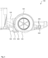
- Figure 3 shows a longitudinal section through an example of a floor vacuum cleaner 100.
- the pins 240 rest on the bottom of the receptacles 245 or on the chassis 105.
- the suction mouth 120 is attached by the pipe socket 130 opposite the chassis 105 or the suction unit 135 attached to the chassis 105.
- the pipe socket 130 is made of a flexible material, preferably plastic, for example an elastomer.
- Elastic properties of the pipe socket 130 can be influenced by its shape, its wall thickness or its material.
- An elastic force that is caused by the pipe socket 130 when it is subjected to shear stress when the suction mouth 120 pivots about the transverse axis 205 can be determined independently of an elastic force that it exerts when the suction mouth 120 rotates about the longitudinal axis 210.
- a rigidity of the pipe socket 130 against rotation about the longitudinal axis 210 can be lower if a cross section of the pipe socket 130 is oval or flat, and greater if its cross section is round.
- a sealing lip 305 is attached to the suction mouth 120, which preferably extends parallel to the transverse axis 205.
- a sliding element 310 which is designed to rest on the floor surface 115 or to slide over it, is further preferably attached behind the sealing lip 305 to the suction mouth 120.
- Figures 4 and 5 show views of a suction mouth 120 in an exemplary embodiment. It can be seen that the pins 240 are placed here on the suction mouth 120 in front of a boundary of the area through which air flows.
- the pipe socket 130 has a horizontally flattened cross-section.
- a flange 405 for attachment to the chassis 105 or the suction unit 135 can be provided at a rear end of the pipe socket 130.
- Figure 6 shows a view of a suction mouth 120 of a floor vacuum cleaner 100 from below.
- the brush roller 125 comprises, for example, double helical flutes that are formed from rows of bristles.
- the chassis can be reinforced by longitudinal ribs.
Landscapes
- Engineering & Computer Science (AREA)
- Mechanical Engineering (AREA)
- Nozzles For Electric Vacuum Cleaners (AREA)
Abstract
Description
- Die Erfindung betrifft einen automatischen Bodenreiniger mit einem Saugwerk. Insbesondere betrifft die Erfindung die Lagerung des Saugmunds gegenüber einem Chassis des Bodenreinigers.
- Ein Bodensauger ist dazu eingerichtet, auf einer Bodenfläche zu fahren und sie dabei zu reinigen. Dazu umfasst der Bodensauger ein Saugwerk, das einen Luftstrom durch einen Saugmund bewirkt, der an einem Chassis des Bodensaugers angebracht ist. Der Saugmund soll in einem vorbestimmten Abstand von der Bodenfläche liegen, um einen horizontalen Eintritt von Grobschmutz oder Fremdkörpern nicht zu behindern. Der Abstand soll aber auch nicht zu groß sein, um die Luftströmung effizient zur Aufnahme von Schmutz nutzen zu können.
- Ist der Saugmund starr am Chassis angebracht, so kann er gegen ein Hindernis laufen und die Bewegung des Bodensaugers behindern. Ist der Saugmund vertikal beweglich angeordnet, kann der Abstand zur Bodenfläche beispielsweise beim Überfahren einer Kante oder Schwelle vorübergehend zu gering oder zu groß sein. Zur beweglichen Lagerung eines Saugmunds gegenüber einem Chassis wurden unterschiedliche Vorschläge gemacht.
-
DE 10 2010 000 577 A1 betrifft einen Bodensauger mit einem Saugmund, der an einem bezüglich der Fahrtrichtung hinteren Ende schwenkbar gelagert ist. An einem vorderen Ende ist eine Führung aus einer Kulisse und einem Kulissenstein vorgesehen, um eine vertikale Bewegung zu erlauben. Mittels einer Schraubenfeder wird das vordere Ende am Chassis in Richtung der Bodenfläche gedrückt. Eine Aufnahme von Grobgut in den Bereich des Saugmunds kann dadurch behindert werden. - Eine der vorliegenden Erfindung zu Grunde liegende Aufgabe besteht in der Bereitstellung einer verbesserten Technik zur flexiblen Anbindung eines Saugmunds an einem Bodensauger. Die Erfindung löst diese Aufgabe mittels der Gegenstände der unabhängigen Ansprüche. Unteransprüche geben bevorzugte Ausführungsformen wieder.
- Ein Bodensauger zur Reinigung einer Bodenfläche umfasst ein Chassis mit einem Fahrwerk zum Fahren auf der Bodenfläche; und einen Saugmund zum Einlassen eines Luftstroms im Bereich der Bodenfläche, wobei der Saugmund in Fahrtrichtung vorne links und rechts jeweils mittels einer Anordnung aus einem Zapfen und einer Führung derart gegenüber dem Chassis gelagert ist, dass ein Kippen des Saugmunds um die Zapfen, ein Drehen des Saugmunds um eine Längsachse sowie eine vertikale Bewegung des Saugmunds ermöglicht sind, aber eine Bewegung des Saugmunds in Längsrichtung des Chassis verhindert ist.
- Durch diese Lagerung kann der Saugmund verbessert in einer vorteilhaften Position gegenüber dem Untergrund gehalten werden. Beim Überfahren einer Unebenheit kann der Saugmund trotzdem so gehalten sein, dass Schmutz effektiv von der Bodenfläche aufgenommen wird. Der Saugmund kann beim Überfahren einer Schwelle oder Stufe, eines Übergangs zwischen verschiedenen Bodenbelägen, eines Kabels, einer Fuge oder eines anderen Hindernisses verbessert am Untergrund entlanggeführt werden kann. Er kann in drei vorbestimmten Freiheitsgraden beweglich sein, wobei ein erster Freiheitsgrad ein Kippen des Saugmunds um eine Querachse des Bodensaugers, ein zweiter Freiheitsgrad ein Schwenken um eine Längsachse und ein dritter Freiheitsgrad ein Verschieben entlang einer Hochachse betrifft.
- Optional kann der Saugmund auch entlang einer Querachse des Chassis verschoben werden. Einer Verschiebung aus einer vorbestimmten Position heraus kann ein elastisches Element entgegenwirken. Rückstellkräfte des elastischen Elements für eine Verschiebung nach links und nach rechts können gleich oder unterschiedlich sein. Dazu kann eine Anordnung mit zwei verschiedenen elastischen Elementen eingesetzt werden. Die Verschiebung kann ein- oder zweiseitig auf einen vorbestimmten Weg begrenzt sein.
- Durch die Kombination der beschriebenen Freiheitsgrade kann Grobschmutz verbessert von der Bodenfläche in den Bereich des Saugmunds eintreten und eingesaugt werden. Ein Festfahren des Bodensaugers an einer Kante oder ein Eingraben in einen weichen oder langflorigen Untergrund kann vermieden werden.
- In einer bevorzugten Ausführungsform ist ein Zapfen am Saugmund und eine Führung am Chassis vorgesehen. Dadurch kann eine vertikale Führung des Zapfens verbessert sein. Die Zapfen erstrecken sich entlang einer gemeinsamen Achse und können nach der Art von Schildzapfen beidseitig des Saugmunds ausgebildet sein. Die Aufnahme kann durch zwei zueinander parallele Anlageflächen gebildet sein, die sich jeweils senkrecht zur Längsachse des Chassis erstrecken. Eine Anlagefläche kann beliebig schmal sein; in einer Ausführungsform kann beispielsweise ein vertikaler Zylinder die Anlagefläche bilden. Eine umgekehrte Anordnung, bei welcher ein Zapfen am Chassis und eine Aufnahme am Saugmund vorgesehen ist, kann ebenfalls eingesetzt werden.
- Weiter bevorzugt ist der Saugmund hinten links und rechts vertikal beweglich gelagert. Eine separate Führung in diesem Bereich ist nicht erforderlich. Die Beweglichkeit des Saugmunds kann so umfassend definiert sein.
- In einer einfachen Ausführungsform wird eine vertikale Position des Saugmunds am hinteren Ende durch die Gewichtskraft des Saugmunds oder einer damit verbundenen Komponente definiert. In einer bevorzugten Ausführungsform kann ein elastisches Element vorgesehen sein, das dazu eingerichtet ist, ein hinteres Ende des Saugmunds in eine vorbestimmte vertikale Position gegenüber dem Chassis zu drücken. An einem hinteren linken und einem hinteren rechten Ende kann jeweils ein elastisches Element vorgesehen sein. Ein elastisches Element kann sowohl nach oben als auch nach unten wirken, wobei wirksame Federkonstanten gleich oder unterschiedlich sein können. Am vorderen Ende kann auf ein elastisches Element verzichtet werden; hier kann die vertikale Position bevorzugt aufgrund der Gewichtskraft des Saugmunds oder in Verlängerung des hinteren Endes eingestellt werden.
- Das elastische Element kann durch einen elastischen Rohrstutzen gebildet sein, durch den der Luftstrom aus dem Saugmund in Richtung des Saugwerks fließt. Der Rohrstutzen liegt weiter bevorzugt am Saugmund in Fahrtrichtung hinten und verläuft annähernd horizontal. Die Elastizität des Rohrstutzens kann zur Positionierung des Saugmunds genutzt werden und helfen, ein separates elastisches Element einzusparen. Der Rohrstutzen kann so ausgeführt sein, dass er jeweils vorbestimmte elastische Kräfte gegenüber einer Verdrehung um eine Längsachse (zweiter Freiheitsgrad) und einer vertikalen Auslenkung des Saugmunds (dritter Freiheitsgrad) bereitstellt. Diese Kräfte können durch eine Formgebung und Materialwahl des Saugstutzens in gewissen Grenzen unabhängig voneinander bestimmt sein.
- Weiter bevorzugt ist eine Auslenkung eines hinteren Endes des Saugmunds aus der vorbestimmten Position nach oben und/oder unten auf einen vorbestimmten Weg begrenzt. Ein Auslenkungsweg nach oben kann größer als ein Auslenkungsweg nach unten sein. Beispielsweise kann der Saugmund gegenüber dem Chassis um ca. 4,5 mm nach oben und um ca. 2,3 mm nach unten ausgelenkt werden, bevor ein Anschlag die Bewegung begrenzt.
- Eine Auslenkung des vorderen Endes des Saugmunds nach oben kann auf einen weiteren vorbestimmten Wert begrenzt sein. Dieser Auslenkungsweg kann geringer als ein Auslenkungsweg des hinteren Endes nach oben oder unten sein. In einer Ausführungsform kann das vordere Ende um ca. 1 - 2 mm nach oben ausgelenkt werden. Eine Auslenkung nach unten kann nicht vorgesehen sein bzw. null betragen.
- Im Saugmund ist bevorzugt eine Bürstenwalze mit einer quer zur Fahrtrichtung verlaufenden Drehachse angebracht. Die Bürstenwalze kann mittels eines Antriebsmotors um die Drehachse gedreht werden und ist dazu eingerichtet, Schmutz von der Bodenfläche zu lösen bzw. im Bereich des Saugmunds zu führen. Ein Kontakt der Bürstenwalze mit dem Untergrund kann durch die vorgeschlagene schwimmende Lagerung des Saugmunds verbessert sein, sodass eine Reinigung der Bodenfläche mittels der Bürstenwalze verbessert sein kann.
- Im Bereich eines hinteren Endes des Saugmunds kann eine Dichtlippe vorgesehen sein. Die Dichtlippe erstreckt sich bevorzugt in Querrichtung und ist dazu eingerichtet, an der Bodenfläche möglichst anzuliegen und den Saugmund gegenüber der Bodenfläche abzudichten. Dazu ist die Dichtlippe bevorzugt aus einem elastischen Material gefertigt, sodass sie bei Bedarf an einem Hindernis oder einer Unebenheit an der Bodenfläche elastisch verformt werden kann. Eine Dichtwirkung der Dichtlippe gegenüber der Bodenfläche kann durch die beschriebene Beweglichkeit des Saugmunds bezüglich des Chassis weiter verbessert sein.
- Zur Abstützung eines hinteren Endes des Saugmunds gegenüber der Bodenfläche kann ein Gleitelement vorgesehen sein. Das Gleitelement kann eine Oberfläche aus Kunststoff oder Textil (Fadenheber) aufweisen. Ist eine Dichtlippe vorgesehen, so liegt das Gleitelement bezüglich der Fahrtrichtung noch hinter der Dichtlippe.
- Das Fahrwerk kann ein Antriebsrad und eine Steuervorrichtung umfassen, um eine Bewegung des Bodensaugers auf der Bodenfläche zu steuern. Der Bodensauger ist bevorzugt zur autonomen Bearbeitung einer Bodenfläche vorgesehen. Die Bodenfläche ist weiter bevorzugt von einem Haushalt umfasst und kann beispielsweise die eines oder mehrerer Zimmer betreffen.
- Die Erfindung wird nun unter Bezug auf die beiliegenden Figuren genauer beschrieben, in denen:
- Figur 1
- einen Bodensauger;
- Figur 2
- eine Prinzipdarstellung einer schwimmenden Lagerung eines Saugmunds;
- Figur 3
- einen Längsschnitt durch einen Bodensauger;
- Figur 4
- eine erste Ansicht eines Saugmunds eines Bodensaugers;
- Figur 5
- eine zweite Ansicht eines Saugmunds eines Bodensaugers;
- Figur 6
- eine Ansicht eines Saugmunds eines Bodensaugers von unten;
-
Figur 1 zeigt einen beispielhaften Bodensauger 100. Ein oberer Teil eines Gehäuses und einige für die Vorstellung der Erfindung nicht relevante Elemente sind nicht dargestellt. Der Bodensauger 100 umfasst ein Chassis 105 mit einem Fahrwerk 110, das dazu eingerichtet ist, das Chassis 105 gegenüber einer Bodenfläche 115 abzustützen. Bevorzugt umfasst das Fahrwerk 110 wenigstens ein Antriebsrad, das mittels eines Antriebsmotors angetrieben werden kann. Außerdem kann eine Steuervorrichtung zur Steuerung des Antriebsmotors und/oder einer Lenkung vorgesehen sein. Die Steuervorrichtung ist bevorzugt dazu eingerichtet, eine autonome Bewegung des Bodensaugers 100 auf der Bodenfläche 115 zu steuern. Im Betrieb kann der Bodensauger 100 dazu angesteuert werden, einen vorbestimmten Abschnitt der Bodenfläche 115 abzufahren und dabei zu bearbeiten. - Zur Bearbeitung der Bodenfläche 115 ist ein Saugmund 120 vorgesehen, in welchem vorliegend eine Bürstenwalze 125 mit einer horizontalen Drehachse angeordnet ist. Über einen Rohrstutzen 130 ist der Saugmund 120 mit einem Saugwerk 135 verbunden, das bevorzugt bezüglich einer Fahrtrichtung 140 hinter dem Saugmund 105 angeordnet ist. Das Saugwerk 135 ist in
Figur 1 nicht direkt sichtbar und befindet sich in dem dargestellten Filtergehäuse. Der Saugmund 120 bildet eine Kammer mit einer hinteren Öffnung, die mit dem Rohrstutzen 130 verbunden ist, und einer unteren Öffnung, durch welche ein Abschnitt der Bürstenwalze 125 ragen kann und durch welche ein Luftstrom eintreten kann. Die Bürstenwalze 125 kann mittels eines Antriebsmotors (nicht dargestellt) um die Drehachse angetrieben werden, um die Bodenfläche 115 mechanisch zu bearbeiten. Der Saugmund 120 ist beweglich gegenüber dem Chassis 105 und kann gegenüber diesem mittels seiner eigenen Gewichtskraft oder mittels eines elastischen Elements in eine vorbestimmte Position gedrückt werden. Bevorzugt sind Kanten an der Unterseite des Saugmunds 120 abgerundet oder gefast ausgeführt, um den Saugmund 120 bei Kontakt mit einem Hindernis auf der Bodenfläche 115 verbessert nach oben auszulenken. - Es wird vorgeschlagen, den Saugmund 120 in einer Weise beweglich gegenüber dem Chassis 105 zu lagern, die mit Bezug auf
Figur 2 genauer erläutert wird.Figur 2 zeigt eine schematische Darstellung der Lagerung des Saugmunds 120 am Chassis 105. Der Saugmund 120 ist vereinfacht als Rahmen dargestellt und das Chassis 105 vereinfachend als zwei Lagerstellen. - Bezüglich des Chassis 105 sind eine Querachse 205, eine Längsachse 210 und eine Hochachse 215 definiert, die bevorzugt ein Rechtssystem bilden. Um die Querachse 205 kann der Saugmund 120 gekippt werden, was einem ersten Freiheitsgrad 225 entspricht. Um die Längsachse 210 kann der Saugmund 120 geschwenkt werden, was einem zweiten Freiheitsgrad 230 entspricht. Entlang der Hochachse 215 kann der Saugmund 120 verschoben werden, was einem dritten Freiheitsgrad 235 entspricht. Dabei können Bewegungen des Saugmunds in den Freiheitsgraden 225 bis 235 auf vorbestimmte Weise miteinander gekoppelt sein.
- Eine Bewegung entlang der Querachse 205 ist in der dargestellten Ausführungsform durch laterale Abstände zwischen dem Saugmund 120 und den Lagerstellen auf einem vorbestimmten Weg ermöglicht. Dabei kann ein elastisches Element eine Rückstellung in eine vorbestimmte Position bewirken, wenn der Saugmund 120 horizontal ausgelenkt wird. Das elastische Element kann dieser Bewegung zugeordnet sein. In einer anderen Ausführungsform ist diese Bewegung verhindert, beispielsweise indem die genannten Abstände nahe null betragen. Entlang der Längsachse 210 ist der Saugmund 120 bevorzugt unbeweglich. Eine Drehung um die Hochachse 215 ist bevorzugt ebenfalls verhindert. Insgesamt ist der Saugmund 120 auf diese Weise in 4 bzw. 3 Freiheitsgraden beweglich und in den verbleibenden 2 bzw. 3 Freiheitsgraden unbeweglich.
- Am Saugmund 120 sind mit Bezug auf die Fahrtrichtung 140 vorne links und rechts je ein Zapfen 240 angebracht, wobei sich die Zapfen 240 entlang einer gemeinsamen Drehachse erstrecken. In der dargestellten schematischen Darstellung sind die Zapfen 240 Teil einer durchgehenden Achse, in einer anderen Ausführungsform kann die Achse auch unterbrochen sein. Jeder Zapfen 240 ist am Chassis 105 in einer Aufnahme 245 aufgenommen, die eine Bewegung des Zapfens 240 in Richtung der Längsachse 210 verhindert, wodurch auch ein Drehen des Saugmunds 120 um die Hochachse 215 verhindert ist. Eine Bewegung des Saugmunds 120 entlang der Hochachse 215 ist jedoch in einem vorbestimmten Maß möglich. Eine Aufnahme 245 umfasst ein vertikales Langloch in der dargestellten Lagerstelle, wobei sich ein Zapfen 240 durch das Langloch erstreckt. Begrenzungen des Langlochs legen eine maximale Auslenkung des Zapfens 240 bzw. des Saugmunds 120 nach oben und unten fest. Durch die unabhängige Lagerung der beiden Zapfen 240 ist auch ein Kippen des Saugmunds 120 um die Längsachse 210 möglich.
- Bezüglich der Fahrtrichtung 140 hinten ist links und rechts je ein elastisches Element 250 vorgesehen, um den Saugmund 120 in diesem Bereich in eine vorbestimmte Position zu bewegen. Optional ist ein elastisches Element 250 doppelt wirkend oder es sind zwei antiparallel wirkende elastische Elemente 250 vorgesehen, sodass einer Auslenkung des Saugmunds 120 aus der vorbestimmten Position sowohl nach oben als auch nach unten durch eine entsprechende Rückstellkraft entgegengewirkt wird. Dabei können Federhärten in beiden Richtungen gleich oder unterschiedlich sein. Das elastische Element 250 kann vorgespannt sein, sodass eine Auslenkung des Saugmunds 120 aus der vorbestimmten Position eine vorbestimmte Mindestkraft erfordert.
- An den Zapfen 240 können ebenfalls elastische Elemente 250 vorgesehen sein oder eine vertikale Position des Saugmunds 120 in diesem Bereich kann vornehmlich durch eine Gewichtskraft auf den Saugmund 120 bestimmt sein.
-
Figur 3 zeigt einen Längsschnitt durch einen beispielhaften Bodensauger 100. In der dargestellten Position liegen die Zapfen 240 unten an den Aufnahmen 245 bzw. am Chassis 105 auf. Im hinteren Bereich ist der Saugmund 120 durch den Rohrstutzen 130 gegenüber dem Chassis 105 bzw. dem am Chassis 105 befestigten Saugwerk 135 angebracht. Der Rohrstutzen 130 ist aus einem flexiblen Material gefertigt, vorzugsweise aus Kunststoff, beispielsweise aus einem Elastomer. - Elastische Eigenschaften des Rohrstutzens 130 können über seine Formgebung, seine Wandstärke oder sein Material beeinflusst werden. Dabei kann eine elastische Kraft, die durch den Rohrstutzen 130 bewirkt wird, wenn er bei einem Schwenken des Saugmunds 120 um die Querachse 205 auf Scherung beansprucht wird, unabhängig von einer elastischen Kraft bestimmt sein, die er beim Verdrehen des Saugmunds 120 um die Längsachse 210 ausübt. Beispielsweise kann eine Steifigkeit des Rohrstutzens 130 gegen eine Verdrehung um die Längsachse 210 geringer sein, wenn ein Querschnitt des Rohrstutzens 130 oval oder flach ausgeführt ist, und größer, wenn sein Querschnitt rund ausgeführt ist.
- Hinter der Bürstenwalze 125 ist eine Dichtlippe 305 am Saugmund 120 angebracht, die sich bevorzugt parallel zur Querachse 205 erstreckt. Ein Gleitelement 310, das dazu eingerichtet ist, auf der Bodenfläche 115 aufzuliegen bzw. über sie zu gleiten, ist weiter bevorzugt noch hinter der Dichtlippe 305 am Saugmund 120 angebracht.
-
Figuren 4 und 5 zeigen Ansichten eines Saugmunds 120 in einer beispielhaften Ausführungsform. Es ist zu erkennen, dass die Zapfen 240 hier am Saugmund 120 vor eine Begrenzung des von Luft durchströmten Bereichs verlegt sind. Der Rohrstutzen 130 weist hier einen horizontal abgeflachten Querschnitt auf. An einem hinteren Ende des Rohrstutzens 130 kann ein Flansch 405 zur Anbringung am Chassis 105 bzw. dem Saugwerk 135 vorgesehen sein. -
Figur 6 zeigt eine Ansicht eines Saugmunds 120 eines Bodensaugers 100 von unten. Die Bürstenwalze 125 umfasst beispielhaft doppelt helixförmige Fluten, die aus Reihen von Borsten gebildet sind. In einem Einlassbereich des Saugmunds 120 kann das Chassis durch längs verlaufende Rippen verstärkt sein. -
- 100
- Bodensauger
- 105
- Chassis
- 110
- Fahrwerk
- 115
- Bodenfläche
- 120
- Saugmund
- 125
- Bürstenwalze
- 130
- Rohrstutzen
- 135
- Saugwerk
- 140
- Fahrtrichtung
- 205
- Querachse
- 210
- Längsachse
- 215
- Hochachse
- 225
- erster Freiheitsgrad
- 230
- zweiter Freiheitsgrad
- 235
- dritter Freiheitsgrad
- 240
- Zapfen
- 245
- Aufnahme
- 250
- elastisches Element
- 305
- Dichtlippe
- 310
- Gleitelement
- 405
- Flansch
Claims (11)
- Bodensauger (100) zur Reinigung einer Bodenfläche (115), wobei der Bodenreiniger folgendes umfasst:- ein Chassis (105) mit einem Fahrwerk (110) zum Fahren auf der Bodenfläche (115);- einen Saugmund (120) zum Einlassen eines Luftstroms im Bereich der Bodenfläche (115);- wobei der Saugmund (120) in Fahrtrichtung (140) vorne links und rechts jeweils mittels einer Anordnung aus einem Zapfen (240) und einer Führung (245) derart gegenüber dem Chassis (105) gelagert ist, dass ein Kippen des Saugmunds (120) um die Zapfen (240), ein Drehen des Saugmunds (120) um eine Längsachse (210) sowie eine vertikale Bewegung des Saugmunds (120) ermöglicht sind, aber eine Bewegung des Saugmunds (120) in Längsrichtung des Chassis (105) verhindert ist.
- Bodensauger (100) nach Anspruch 1, wobei ein Zapfen (240) am Saugmund (120) und eine Führung (245) am Chassis (105) vorgesehen sind.
- Bodensauger (100) nach Anspruch 1 oder 2, wobei der Saugmund (120) hinten links und rechts vertikal beweglich gelagert ist.
- Bodensauger (100) nach Anspruch 3, ferner umfassend ein elastisches Element (250), das dazu eingerichtet ist, ein hinteres Ende des Saugmunds (120) in eine vorbestimmte vertikale Position gegenüber dem Chassis (105) zu drücken.
- Bodensauger (100) nach Anspruch 4, wobei das elastische Element (250) durch einen elastischen Rohrstutzen (130) gebildet ist, durch den der Luftstrom fließt.
- Bodensauger (100) nach einem der Ansprüche 3 bis 5, wobei eine Auslenkung eines hinteren Endes des Saugmunds (120) aus der vorbestimmten Position nach oben und unten jeweils auf einen vorbestimmten Weg begrenzt ist.
- Bodensauger (100) nach einem der vorangehenden Ansprüche, wobei eine Auslenkung des vorderen Endes des Saugmunds (120) nach oben auf einen vorbestimmten Wert begrenzt ist.
- Bodensauger (100) nach einem der vorangehenden Ansprüche, wobei im Saugmund (120) eine Bürstenwalze (125) mit einer quer zur Fahrtrichtung (140) verlaufenden Drehachse angebracht ist.
- Bodensauger (100) nach einem der vorangehenden Ansprüche, ferner umfassend eine Dichtlippe (305) im Bereich eines hinteren Endes des Saugmunds (120).
- Bodensauger (100) nach einem der vorangehenden Ansprüche, ferner umfassend ein Gleitelement (310) zur Abstützung eines hinteren Endes des Saugmunds (120) gegenüber der Bodenfläche (115).
- Bodensauger (100) nach einem der vorangehenden Ansprüche, wobei das Fahrwerk (110) ein Antriebsrad und eine Steuervorrichtung umfasst, um eine Bewegung des Bodensaugers (100) auf der Bodenfläche (115) zu steuern.
Applications Claiming Priority (1)
| Application Number | Priority Date | Filing Date | Title |
|---|---|---|---|
| DE102022211259.8A DE102022211259A1 (de) | 2022-10-24 | 2022-10-24 | Bodenreiniger mit beweglich gelagertem Saugmund |
Publications (2)
| Publication Number | Publication Date |
|---|---|
| EP4360524A1 true EP4360524A1 (de) | 2024-05-01 |
| EP4360524B1 EP4360524B1 (de) | 2025-12-10 |
Family
ID=88237819
Family Applications (1)
| Application Number | Title | Priority Date | Filing Date |
|---|---|---|---|
| EP23201169.2A Active EP4360524B1 (de) | 2022-10-24 | 2023-10-02 | Bodenreiniger mit beweglich gelagertem saugmund |
Country Status (3)
| Country | Link |
|---|---|
| US (1) | US20240225388A9 (de) |
| EP (1) | EP4360524B1 (de) |
| DE (1) | DE102022211259A1 (de) |
Families Citing this family (3)
| Publication number | Priority date | Publication date | Assignee | Title |
|---|---|---|---|---|
| CN213850490U (zh) * | 2019-07-29 | 2021-08-03 | 尚科宁家运营有限公司 | 机器人清洁器 |
| DE102024206112A1 (de) * | 2024-06-28 | 2025-12-31 | BSH Hausgeräte GmbH | Saugroboter mit Seitenbürste |
| DE102024129290A1 (de) * | 2024-10-10 | 2026-04-16 | Alfred Kärcher SE & Co. KG | Saugvorrichtung für einen Saugroboter, Saugroboter und ein Verfahren zum Ansteuern eines Saugroboters |
Citations (2)
| Publication number | Priority date | Publication date | Assignee | Title |
|---|---|---|---|---|
| DE102010000577A1 (de) | 2010-02-04 | 2011-08-04 | Vorwerk & Co. Interholding GmbH, 42275 | Bürstengerät |
| DE102014112313A1 (de) * | 2013-08-30 | 2015-03-05 | Wessel-Werk Gmbh | Selbstfahrendes Saugreinigungsgerät |
Family Cites Families (5)
| Publication number | Priority date | Publication date | Assignee | Title |
|---|---|---|---|---|
| SE306814B (de) * | 1965-06-01 | 1968-12-09 | Electrolux Ab | |
| US4976003A (en) * | 1990-04-11 | 1990-12-11 | Williams William H | Cleaning apparatus |
| TWM247170U (en) * | 2003-10-09 | 2004-10-21 | Cheng-Shiang Yan | Self-moving vacuum floor cleaning device |
| DE102008022995B4 (de) * | 2008-05-09 | 2012-05-31 | Wessel-Werk Gmbh | Saugdüse für Bodenstaubsauger |
| KR101573742B1 (ko) * | 2010-10-25 | 2015-12-07 | 삼성전자주식회사 | 로봇청소기 |
-
2022
- 2022-10-24 DE DE102022211259.8A patent/DE102022211259A1/de active Pending
-
2023
- 2023-10-02 EP EP23201169.2A patent/EP4360524B1/de active Active
- 2023-10-23 US US18/492,260 patent/US20240225388A9/en active Pending
Patent Citations (2)
| Publication number | Priority date | Publication date | Assignee | Title |
|---|---|---|---|---|
| DE102010000577A1 (de) | 2010-02-04 | 2011-08-04 | Vorwerk & Co. Interholding GmbH, 42275 | Bürstengerät |
| DE102014112313A1 (de) * | 2013-08-30 | 2015-03-05 | Wessel-Werk Gmbh | Selbstfahrendes Saugreinigungsgerät |
Also Published As
| Publication number | Publication date |
|---|---|
| US20240225388A9 (en) | 2024-07-11 |
| EP4360524B1 (de) | 2025-12-10 |
| US20240130583A1 (en) | 2024-04-25 |
| DE102022211259A1 (de) | 2024-04-25 |
Similar Documents
| Publication | Publication Date | Title |
|---|---|---|
| EP4360524B1 (de) | Bodenreiniger mit beweglich gelagertem saugmund | |
| EP3100659B1 (de) | Reinigungseinrichtung für ein selbstfahrendes bodenbearbeitungsgerät | |
| EP2840183B1 (de) | Selbstfahrende Baumaschine und Verfahren zum Betreiben einer selbstfahrenden Baumaschine | |
| EP2954817B1 (de) | Bodenreinigungsmaschine | |
| EP0611544A1 (de) | Einteilige Staubsaugerdüse | |
| EP2989953A1 (de) | Verwendung einer an einen bodenstaubsauger anschliessbaren saugdüse zum saugen einer textilen bodenfläche, einer gefliesten hartbodenfläche und einer ungefugten glatten hartbodenfläche | |
| EP2116165A2 (de) | Saugdüse für Staubsauger | |
| EP3025626A1 (de) | Bodendüse für ein bodenpflegegerät und verfahren zum herstellen einer bodendüse für ein bodenpflegegerät | |
| EP4309559A2 (de) | Wischvorrichtung für einen bodenreiniger | |
| DE19719495A1 (de) | Wischanordnung für eine Bodenreinigungsmaschine | |
| EP3106567A1 (de) | Bodenreinigungsmaschine mit flüssigkeitsaufnahmeeinrichtung | |
| DE102015105228B4 (de) | Vorrichtung für ein ein saugendes Gebläse aufweisendes Reinigungsgerät | |
| EP3050475A1 (de) | Saugdüse zum saugen von hartbodenflächen | |
| DE102011011852B4 (de) | Verfahren zum Bearbeiten einer Fläche, Bearbeitungsroboter und Mechanismus zum Positionieren eines Reinigungsmoduls | |
| DE102017118487A1 (de) | Saugdüse für ein ein Sauggebläse aufweisendes Reinigungsgerät | |
| DE102014116280A1 (de) | Saugdüse | |
| DE102013105978B4 (de) | Staubsaugerdüse für Matratzen und Polstermöbel | |
| DE102019211044B4 (de) | Roboter zur Oberflächenpflege | |
| DE9205280U1 (de) | Reinigungsanlage für Textilmaschinen | |
| DE10309106A1 (de) | Vorrichtung zur selbstfahrenden Reinigung eines Spaltenbodens eines Tierstalles, insbesondere eines Kuhstalles, und Reinigungswerkzeug | |
| DE3038668A1 (de) | Bodenreinigungskopf | |
| EP3378369A1 (de) | Saugfuss für eine bodenreinigungsmaschine | |
| EP4147621B1 (de) | Vorrichtung zum reinigen einer bodenoberfläche mit seitlichen dichtelementen | |
| DE102014106041A1 (de) | Selbstfahrendes Reinigungsgerät und Betriebsverfahren für ein selbstfahrendes Reinigungsgerät | |
| EP4195988B1 (de) | Bodenbearbeitungseinrichtung |
Legal Events
| Date | Code | Title | Description |
|---|---|---|---|
| PUAI | Public reference made under article 153(3) epc to a published international application that has entered the european phase |
Free format text: ORIGINAL CODE: 0009012 |
|
| STAA | Information on the status of an ep patent application or granted ep patent |
Free format text: STATUS: THE APPLICATION HAS BEEN PUBLISHED |
|
| AK | Designated contracting states |
Kind code of ref document: A1 Designated state(s): AL AT BE BG CH CY CZ DE DK EE ES FI FR GB GR HR HU IE IS IT LI LT LU LV MC ME MK MT NL NO PL PT RO RS SE SI SK SM TR |
|
| STAA | Information on the status of an ep patent application or granted ep patent |
Free format text: STATUS: REQUEST FOR EXAMINATION WAS MADE |
|
| 17P | Request for examination filed |
Effective date: 20241104 |
|
| RBV | Designated contracting states (corrected) |
Designated state(s): AL AT BE BG CH CY CZ DE DK EE ES FI FR GB GR HR HU IE IS IT LI LT LU LV MC ME MK MT NL NO PL PT RO RS SE SI SK SM TR |
|
| GRAP | Despatch of communication of intention to grant a patent |
Free format text: ORIGINAL CODE: EPIDOSNIGR1 |
|
| STAA | Information on the status of an ep patent application or granted ep patent |
Free format text: STATUS: GRANT OF PATENT IS INTENDED |
|
| RIC1 | Information provided on ipc code assigned before grant |
Ipc: A47L 9/04 20060101AFI20250505BHEP |
|
| INTG | Intention to grant announced |
Effective date: 20250522 |
|
| GRAS | Grant fee paid |
Free format text: ORIGINAL CODE: EPIDOSNIGR3 |
|
| GRAA | (expected) grant |
Free format text: ORIGINAL CODE: 0009210 |
|
| STAA | Information on the status of an ep patent application or granted ep patent |
Free format text: STATUS: THE PATENT HAS BEEN GRANTED |
|
| AK | Designated contracting states |
Kind code of ref document: B1 Designated state(s): AL AT BE BG CH CY CZ DE DK EE ES FI FR GB GR HR HU IE IS IT LI LT LU LV MC ME MK MT NL NO PL PT RO RS SE SI SK SM TR |
|
| REG | Reference to a national code |
Ref country code: CH Ref legal event code: F10 Free format text: ST27 STATUS EVENT CODE: U-0-0-F10-F00 (AS PROVIDED BY THE NATIONAL OFFICE) Effective date: 20251210 Ref country code: GB Ref legal event code: FG4D Free format text: NOT ENGLISH |
|
| REG | Reference to a national code |
Ref country code: DE Ref legal event code: R096 Ref document number: 502023002423 Country of ref document: DE |
|
| REG | Reference to a national code |
Ref country code: IE Ref legal event code: FG4D Free format text: LANGUAGE OF EP DOCUMENT: GERMAN |
|
| PG25 | Lapsed in a contracting state [announced via postgrant information from national office to epo] |
Ref country code: ES Free format text: LAPSE BECAUSE OF FAILURE TO SUBMIT A TRANSLATION OF THE DESCRIPTION OR TO PAY THE FEE WITHIN THE PRESCRIBED TIME-LIMIT Effective date: 20251210 |
|
| REG | Reference to a national code |
Ref country code: LT Ref legal event code: MG9D |
|
| PG25 | Lapsed in a contracting state [announced via postgrant information from national office to epo] |
Ref country code: NO Free format text: LAPSE BECAUSE OF FAILURE TO SUBMIT A TRANSLATION OF THE DESCRIPTION OR TO PAY THE FEE WITHIN THE PRESCRIBED TIME-LIMIT Effective date: 20260310 |
|
| PG25 | Lapsed in a contracting state [announced via postgrant information from national office to epo] |
Ref country code: FI Free format text: LAPSE BECAUSE OF FAILURE TO SUBMIT A TRANSLATION OF THE DESCRIPTION OR TO PAY THE FEE WITHIN THE PRESCRIBED TIME-LIMIT Effective date: 20251210 Ref country code: HR Free format text: LAPSE BECAUSE OF FAILURE TO SUBMIT A TRANSLATION OF THE DESCRIPTION OR TO PAY THE FEE WITHIN THE PRESCRIBED TIME-LIMIT Effective date: 20251210 |
|
| REG | Reference to a national code |
Ref country code: NL Ref legal event code: MP Effective date: 20251210 |
|
| PG25 | Lapsed in a contracting state [announced via postgrant information from national office to epo] |
Ref country code: RS Free format text: LAPSE BECAUSE OF FAILURE TO SUBMIT A TRANSLATION OF THE DESCRIPTION OR TO PAY THE FEE WITHIN THE PRESCRIBED TIME-LIMIT Effective date: 20260310 |
|
| PG25 | Lapsed in a contracting state [announced via postgrant information from national office to epo] |
Ref country code: LV Free format text: LAPSE BECAUSE OF FAILURE TO SUBMIT A TRANSLATION OF THE DESCRIPTION OR TO PAY THE FEE WITHIN THE PRESCRIBED TIME-LIMIT Effective date: 20251210 |
|
| PG25 | Lapsed in a contracting state [announced via postgrant information from national office to epo] |
Ref country code: BG Free format text: LAPSE BECAUSE OF FAILURE TO SUBMIT A TRANSLATION OF THE DESCRIPTION OR TO PAY THE FEE WITHIN THE PRESCRIBED TIME-LIMIT Effective date: 20251210 |