EP4359653B1 - Kogenerationsverfahren und zugehörige vorrichtung - Google Patents
Kogenerationsverfahren und zugehörige vorrichtung Download PDFInfo
- Publication number
- EP4359653B1 EP4359653B1 EP22741848.0A EP22741848A EP4359653B1 EP 4359653 B1 EP4359653 B1 EP 4359653B1 EP 22741848 A EP22741848 A EP 22741848A EP 4359653 B1 EP4359653 B1 EP 4359653B1
- Authority
- EP
- European Patent Office
- Prior art keywords
- syngas
- burner
- combustion
- phase
- temperature
- Prior art date
- Legal status (The legal status is an assumption and is not a legal conclusion. Google has not performed a legal analysis and makes no representation as to the accuracy of the status listed.)
- Active
Links
Images

Classifications
-
- F—MECHANICAL ENGINEERING; LIGHTING; HEATING; WEAPONS; BLASTING
- F01—MACHINES OR ENGINES IN GENERAL; ENGINE PLANTS IN GENERAL; STEAM ENGINES
- F01N—GAS-FLOW SILENCERS OR EXHAUST APPARATUS FOR MACHINES OR ENGINES IN GENERAL; GAS-FLOW SILENCERS OR EXHAUST APPARATUS FOR INTERNAL-COMBUSTION ENGINES
- F01N5/00—Exhaust or silencing apparatus combined or associated with devices profiting by exhaust energy
- F01N5/02—Exhaust or silencing apparatus combined or associated with devices profiting by exhaust energy the devices using heat
-
- F—MECHANICAL ENGINEERING; LIGHTING; HEATING; WEAPONS; BLASTING
- F23—COMBUSTION APPARATUS; COMBUSTION PROCESSES
- F23B—METHODS OR APPARATUS FOR COMBUSTION USING ONLY SOLID FUEL
- F23B50/00—Combustion apparatus in which the fuel is fed into or through the combustion zone by gravity, e.g. from a fuel storage situated above the combustion zone
- F23B50/02—Combustion apparatus in which the fuel is fed into or through the combustion zone by gravity, e.g. from a fuel storage situated above the combustion zone the fuel forming a column, stack or thick layer with the combustion zone at its bottom
- F23B50/06—Combustion apparatus in which the fuel is fed into or through the combustion zone by gravity, e.g. from a fuel storage situated above the combustion zone the fuel forming a column, stack or thick layer with the combustion zone at its bottom the flue gases being removed downwards through one or more openings in the fuel-supporting surface
-
- F—MECHANICAL ENGINEERING; LIGHTING; HEATING; WEAPONS; BLASTING
- F23—COMBUSTION APPARATUS; COMBUSTION PROCESSES
- F23B—METHODS OR APPARATUS FOR COMBUSTION USING ONLY SOLID FUEL
- F23B90/00—Combustion methods not related to a particular type of apparatus
- F23B90/04—Combustion methods not related to a particular type of apparatus including secondary combustion
- F23B90/06—Combustion methods not related to a particular type of apparatus including secondary combustion the primary combustion being a gasification or pyrolysis in a reductive atmosphere
-
- F—MECHANICAL ENGINEERING; LIGHTING; HEATING; WEAPONS; BLASTING
- F23—COMBUSTION APPARATUS; COMBUSTION PROCESSES
- F23G—CREMATION FURNACES; CONSUMING WASTE PRODUCTS BY COMBUSTION
- F23G5/00—Incineration of waste; Incinerator constructions; Details, accessories or control therefor
- F23G5/02—Incineration of waste; Incinerator constructions; Details, accessories or control therefor with pretreatment
- F23G5/027—Incineration of waste; Incinerator constructions; Details, accessories or control therefor with pretreatment pyrolising or gasifying stage
-
- F—MECHANICAL ENGINEERING; LIGHTING; HEATING; WEAPONS; BLASTING
- F23—COMBUSTION APPARATUS; COMBUSTION PROCESSES
- F23G—CREMATION FURNACES; CONSUMING WASTE PRODUCTS BY COMBUSTION
- F23G5/00—Incineration of waste; Incinerator constructions; Details, accessories or control therefor
- F23G5/44—Details; Accessories
- F23G5/46—Recuperation of heat
-
- F—MECHANICAL ENGINEERING; LIGHTING; HEATING; WEAPONS; BLASTING
- F23—COMBUSTION APPARATUS; COMBUSTION PROCESSES
- F23G—CREMATION FURNACES; CONSUMING WASTE PRODUCTS BY COMBUSTION
- F23G7/00—Incinerators or other apparatus for consuming industrial waste, e.g. chemicals
- F23G7/10—Incinerators or other apparatus for consuming industrial waste, e.g. chemicals of field or garden waste or biomasses
-
- F—MECHANICAL ENGINEERING; LIGHTING; HEATING; WEAPONS; BLASTING
- F02—COMBUSTION ENGINES; HOT-GAS OR COMBUSTION-PRODUCT ENGINE PLANTS
- F02G—HOT GAS OR COMBUSTION-PRODUCT POSITIVE-DISPLACEMENT ENGINE PLANTS; USE OF WASTE HEAT OF COMBUSTION ENGINES; NOT OTHERWISE PROVIDED FOR
- F02G2243/00—Stirling type engines having closed regenerative thermodynamic cycles with flow controlled by volume changes
-
- F—MECHANICAL ENGINEERING; LIGHTING; HEATING; WEAPONS; BLASTING
- F23—COMBUSTION APPARATUS; COMBUSTION PROCESSES
- F23G—CREMATION FURNACES; CONSUMING WASTE PRODUCTS BY COMBUSTION
- F23G2206/00—Waste heat recuperation
- F23G2206/20—Waste heat recuperation using the heat in association with another installation
-
- F—MECHANICAL ENGINEERING; LIGHTING; HEATING; WEAPONS; BLASTING
- F23—COMBUSTION APPARATUS; COMBUSTION PROCESSES
- F23G—CREMATION FURNACES; CONSUMING WASTE PRODUCTS BY COMBUSTION
- F23G2900/00—Special features of, or arrangements for incinerators
- F23G2900/50204—Waste pre-treatment by pyrolysis, gasification or cracking
-
- F—MECHANICAL ENGINEERING; LIGHTING; HEATING; WEAPONS; BLASTING
- F23—COMBUSTION APPARATUS; COMBUSTION PROCESSES
- F23N—REGULATING OR CONTROLLING COMBUSTION
- F23N2223/00—Signal processing; Details thereof
- F23N2223/12—Integration
-
- F—MECHANICAL ENGINEERING; LIGHTING; HEATING; WEAPONS; BLASTING
- F23—COMBUSTION APPARATUS; COMBUSTION PROCESSES
- F23N—REGULATING OR CONTROLLING COMBUSTION
- F23N2227/00—Ignition or checking
- F23N2227/02—Starting or ignition cycles
Definitions
- the present invention relates to a process of cogeneration of electrical energy and heat and the related apparatus.
- the present invention relates to a process of cogeneration of electrical energy and heat and the related apparatus for household or small consumer use, starting from a renewable and sustainable energy source, e.g., woody biomass.
- Biomass-fueled cogeneration systems consisting of three basic parts, i.e. a pyrolytic gasifier, a burner, and a Stirling engine, are well known.
- the fuel syngas is produced starting from the biomass in the pyrolytic gasifier; the syngas produced is burned with a controlled supply of air in the burner; the Stirling engine, by virtue of the heat generated by the combustion of the syngas, sets the electric generator in oscillation, thus producing electrical energy.
- Pyrolytic gasification is a thermal-chemical process by virtue of which a combustible gas (syngas), comprising a mixture of hydrogen, carbon monoxide, methane and, to a lesser extent, other compounds, can be extracted from organic material, such as biomass.
- Syngas combustible gas
- Pyrolytic gasification occurs by maintaining the biomass at a particularly high temperature in a low-oxygen environment.
- the by-product of pyrolytic gasification is a solid residue, named char, which contains almost exclusively carbon.
- pyrolytic gasification compared with direct combustion of the biomass, reduces carbon emissions into the atmosphere because, once the fuel syngas is extracted, only the char remains which contains the portion of carbon that will not be emitted into the atmosphere in the form of CO 2 , but is evacuated in solid form and collected. Furthermore, the use of pyrolytic gasification provides a fuel gas which is much more effective in the combustion in terms of maximum achievable temperature, emissions of particulate matter and heating of the heat exchangers.
- JP 2005/274123 discloses a power generation system and a control method thereof.
- EP 2 522 708 discloses an apparatus and a method for gasifying biomass.
- the problem underlying the present invention is to make available a cogeneration process for domestic use and related apparatus capable of high-performance characteristics under all circumstances and of meeting all the requirements explained above.
- a first object of the invention is a process of cogeneration of electrical energy and heat starting from a renewable and sustainable energy source, preferably woody biomass, in a micro-cogenerator comprising a pyrolytic gasifier, a burner, and a Stirling engine, said process comprising the following steps:
- said step b) further comprises the generation of an ignition spark; more in particular, said ignition spark is advantageously generated before the supply of said combustion air.
- said ignition spark is generated at the beginning of the start-up phase.
- Said ignition spark of the flame is generated by a high-voltage electronic transformer.
- the onset (ignition) of the combustion inside the burner is performed by means of an electric arc generated by a high-voltage electronic transformer and related electrodes appropriately positioned, such as to be lapped by the gas flow.
- first threshold value means the preset threshold value of the integral over time of the temperature of the reaction chamber of the pyrolytic gasifier.
- second threshold value means the preset threshold value of the integral over time of the value read by the lambda probe.
- the process according to the present invention allows detecting the time when the pyrolytic gasifier begins to produce fuel syngas and, consequently, the time when the latter is available for combustion in the burner. Detecting the presence of fuel syngas in the burner is critical to identify the exact moment in which the burner can be ignited, the latter being a crucial stage for the following reasons.
- said start-up phase further comprises a step c) of detecting the presence of the flame in the combustion chamber of the burner.
- step c) the derivative of the temperature, i.e., the temperature gradient, of the combustion chamber with respect to time is compared with a preset threshold value of said derivative; the exceeding of said threshold value is an indication of the presence of the flame.
- two thermocouples are placed in the hot exchanger of the Stirling engine and, during the aforesaid step c), the value of the gradient of the average temperature of the two thermocouples is compared with said threshold value.
- the lambda probe provides an electrical signal (in mV) through which it is possible to have a measurement of the "lambda value ( ⁇ )" properly so called, i.e., the ratio between the actual AFR (air-fuel-ratio) and the stoichiometric AFR (air-fuel-ratio); in other words, the "lambda value ( ⁇ )" properly so called is to be understood as the ratio of air to fuel relative to the stoichiometric ratio of the fuel used.
- the electrical signal provided by the lambda probe is an indirect measurement of said lambda value ( ⁇ ); the higher the value of the electrical signal, the lower the lambda value ( ⁇ ).
- the "value read by the lambda probe” means the electrical signal provided by the lambda probe, while the "lambda value ( ⁇ )” means the theoretical value properly so called as defined above.
- a lambda value ( ⁇ ) equal to 0 indicates the presence of syngas only and the absence of air
- a lambda value ( ⁇ ) of 1 indicates the presence of air in stoichiometric amount
- a lambda value ( ⁇ ) greater than 1 indicates the presence of air in excess of the amount strictly necessary for syngas combustion.
- the lambda value ( ⁇ ) is 0 or close to 0, e.g., it is comprised between 0 and 0.2.
- the lambda value ( ⁇ ) is higher, preferably it is about 1, e.g., it is comprised between 0.9 and 1.1.
- the value read by the lambda probe is lower than during the start-up phase, hence the lambda value ( ⁇ ) is higher; preferably the lambda value ( ⁇ ) is higher than 1, e.g., is comprised between 1.1 and 1.5.
- the mV values of the electrical signal provided by the lambda probe were detected experimentally with the lambda probe NGK - OZA685-WW1.
- said step c) further comprises a control of the value read by the lambda probe.
- a value comprised between 0 and 1000 mV e.g., comprised between 5 and 960 mV, or between 10 and 900 mV, or between 50 and 800 mV, is an indication of the presence of the flame.
- threshold value means a calibratable threshold value, i.e., subject to calibration by means of experimental tests.
- the threshold value of the integral over time of the temperature of the reaction chamber of the gasifier (first threshold value) is preferably comprised between 5000 and 25000 °C ⁇ s, more preferably between 10000 and 20000 °C ⁇ s, even more preferably between 13000 and 18000 °C ⁇ s, e.g., it is 15000 °C ⁇ s.
- the threshold value of the integral over time of the value read by the lambda probe is preferably comprised between 500 and 5000 mV ⁇ s, more preferably between 800 and 3000 mV ⁇ s, even more preferably between 1000 and 2000 mV ⁇ s, e.g, it is 2000 mV ⁇ s.
- the aforesaid integral over time of the temperature of the reaction chamber of the gasifier is calculated, then compared with the corresponding threshold value (first threshold value), for temperatures of the reaction chamber of the gasifier of at least 300°C, preferably of at least 400°C, or at least 500°C, or at least 600°C, or at least 700°C, or at least 800°C.
- the aforesaid integral over time of the value read by the lambda probe is calculated, then compared with the corresponding threshold value (second threshold value), for values read by the lambda probe of at least 400 mV, preferably of at least 500 mV, or at least 600 mV, or at least 700 mV, or at least 800, or at least 900, or at least 1000 mV.
- the integral over time of the value read by the lambda probe is calculated, then compared with the corresponding threshold value, for values read by the lambda probe of at least 850 mV.
- the threshold value of the derivative of the temperature of the combustion chamber with respect to time is preferably comprised between 0.1 and 5.0 °C/s, more preferably between 0.3 and 2.0 °C/s, even more preferably between 0.5 and 1.0 °C/s, e.g., it is 0.5°C/s.
- the regime phase is started at the end of the start-up phase and is characterized by a lower value read by the lambda probe, i.e., a higher combustion air-syngas ratio, than the start-up phase. More advantageously, the regime phase is started at the end of said step c).
- the combustion air-syngas ratio is regulated by a lambda probe crossed by a flow of said exhaust fumes, meaning that said combustion air-syngas ratio is adjusted based on the signal provided by said lambda probe.
- the combustion air inflow is advantageously adjusted by means of an electronically-driven motorized valve.
- a valve is driven based on a signal provided by the lambda probe, i.e., based on the information provided by the lambda probe about the amount of air present in the exhaust fumes.
- the excess air is comprised between 1 and 15%, or between 3 and 10%.
- the need to carefully control the amount of air is related to the fact that performance (in terms of burner power) and emissions (CO, NO x ) are strongly affected by the fuel/combustion air ratio.
- An optimal ratio of combustion air to syngas can be maintained by virtue of the signal provided by the lambda probe. Said ratio of combustion air to syngas is kept substantially constant during the regime phase.
- the optimal value read by the lambda probe is identified as compromise between performance and emissions, which is used as an input to a PID controller.
- the optimal lambda value ( ⁇ ) during the regime phase is greater than 1.
- the position of the valve which regulates the combustion air supply is calculated by a PID (Proportional Integrative Derivative) control, which takes as input the value read by the lambda probe and outputs the position of the air adjustment valve.
- the position of the valve which adjusts the supply of combustion air is calculated by a PID control.
- step ii) the syngas exiting the pyrolytic gasifier is sucked into the combustion chamber of the burner by virtue of the presence of a vacuum generated by an appropriate extraction fan of said exhaust fumes.
- said extraction fan is active with a speed proportional to the temperature of the reaction chamber of the pyrolytic gasifier during the start-up phase.
- the extraction fan is driven by taking into account a power error (or delta) or by taking into account a temperature error (or delta).
- the electrical power of the micro-cogenerator is compared with a target electrical power thus obtaining a power delta, and the speed of the extraction fan is adjusted, i.e., increased or decreased as needed, as a function of the power delta thus obtained.
- the speed of the extraction fan is increased until the temperature of the burner exceeds a predetermined limit value.
- the temperature of the burner is compared with a target temperature thus obtaining a temperature delta and the speed of the extraction fan is adjusted, i.e., increased or decreased as needed, as a function of the temperature delta.
- biomass should by no means be understood as limiting.
- the biomass is fed to the pyrolytic gasifier through an appropriate loading auger.
- the latter is advantageously started whenever the filling level of a connecting element (so-called “buffer") between the loading auger and the inlet of the reaction chamber of the pyrolytic gasifier is below a predetermined threshold value.
- the filling level of said connecting element is advantageously detected by a suitable sensor, preferably based on ultrasound technology.
- the reaction chamber of the pyrolytic gasifier is maintained at a suitable gasification temperature at which the biomass reacts generating syngas and biochar.
- Said gasification temperature is preferably comprised between 1000°C and 1200°C to maximize syngas production.
- the reaction front of the biomass inside the gasifier is comprised between an upper limit and a lower limit, and the biomass under reaction is supported by the biochar accumulated in the gasifier as long as the integral over time of the temperature of the upper limit of the reaction front does not exceed a preset threshold value of said integral; when said threshold value is exceeded, the biochar is at least partially discharged through an unloading auger causing the reaction front to lower so that it is maintained between said upper limit and said lower limit.
- threshold value means a calibratable threshold value, i.e., subject to calibration by means of experimental tests.
- the aforesaid threshold value of the integral over time of the temperature of the upper limit of the biomass reaction front inside the gasifier is preferably comprised between 10000 and 90000 °C ⁇ s, more preferably between 15000 and 80000 °C ⁇ s, even more preferably between 20000 and 70000 °C ⁇ s, e.g., is 50000 °C ⁇ s.
- the aforesaid integral over time of the temperature of the upper limit of the biomass reaction front inside the gasifier is calculated, then compared with the corresponding threshold value, for temperatures of said upper limit of at least 300°C, preferably of at least 400°C, or at least 500°C, or at least 600°C, or at least 700°C, or at least 800°C.
- said lower limit is defined by an electric heater placed inside the reaction chamber by virtue of which the gasification reaction of the biomass is initiated, while said upper limit is defined by a thermocouple designed to monitor the temperature in the upper part of the reaction chamber.
- a thermocouple designed to monitor the temperature in the upper part of the reaction chamber.
- temperature of the reaction chamber of the gasifier means the temperature of the electric heater when the process according to the present invention is in its start-up phase, and it means the temperature measured by the thermocouple when the process according to the present invention is in its regime phase.
- a further object of the present invention is a micro-cogenerator comprising:
- said means adapted to convey syngas and air into the combustion chamber consists of a nozzle or a duct; preferably, said nozzle or duct is made of ceramic material.
- said means is a hole made in the insulating material that internally lines the bell.
- said insulating material has a hole at the outlet of the pre-mixing flanges.
- the aforesaid bell In addition to constraining the hot combustion gases to flow through the entire hot exchanger of the Stirling engine, the aforesaid bell also has the advantage of optimizing heat exchange by radiation.
- porous ceramic means the element made of porous ceramic material will be also referred to as a "porous ceramic means".
- the porous ceramic means is thermally insulated from the bell by virtue of the presence of the refractory insulating material covering it.
- said porous ceramic means allows to stabilize the combustion, optimize the distribution thereof, and extend the flammability limit to higher air-fuel ratios, thus allowing to reduce polluting emissions at the exhaust.
- said combustion chamber comprises an additional element made of refractory insulating material interposed between said porous ceramic means and said hot exchanger of the Stirling engine.
- Said additional element has the advantage of preventing the unwanted entrance of heat into a part of the Stirling engine where it would reduce the thermodynamic efficiency of the engine itself.
- said refractory insulating material is a polycrystalline alumina fiber-based material, which ensures high reflection of radiations and reduced heat accumulation.
- said material comprises at least 70% by weight of polycrystalline alumina, preferably at least 75% by weight, more preferably at least 80% by weight, for example about 90% by weight.
- said material further comprises at least 5% by weight of silica, preferably between 10% and 30% by weight of silica, more preferably between 10% and 25% by weight of silica, even more preferably between 10% and 20% by weight of silica.
- said polycrystalline alumina fiber-based material is produced by the company Schupp under the trade name ITM-Fibermax ® , preferably Blanket 1600-130.
- said porous ceramic material comprises silicon carbide, alumina and silica.
- said porous ceramic material is produced by the company Lanik under the trade name Vukopor ® S.
- said porous ceramic material comprises alumina, silica, zirconia and magnesium oxide.
- said porous ceramic material is produced by the company Lanik under the trade name Vukopor ® HT.
- the micro-generator comprises a cooling ring downstream of the hot exchanger of the Stirling engine inside which a cooling fluid flows.
- Said cooling ring is such to prevent heat transfer downstream of said hot exchanger, preventing the entry of unwanted heat into the part of the Stirling engine below the hot exchanger, which comprises, for example, a regenerator, a low-temperature heat exchanger and an electric generator, safeguarding these components from an excessive heating.
- the process and the micro-cogenerator according to the present invention advantageously allow to maximize the syngas combustion efficiency, minimize the production of polluting gases, maximize the heat exchange with the Stirling engine, minimize the entry of heat through unwanted points of the engine which would reduce the efficiency thereof, minimize the heat capacity of the elements close to the hot exchanger of the Stirling engine and reduce the thermal inertia in case of an emergency shutdown, make combustion safe under all circumstances, simplify construction and periodic maintenance.
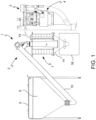
- a micro-cogenerator according to an embodiment of the present invention is globally indicated with reference numeral 1.
- Said micro-cogenerator 1 comprises a pyrolytic gasifier 2, a burner 3, and a Stirling engine 4.
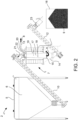
- the pyrolytic gasifier 2 is shown in more detail in Figure 2 , while the burner 3 and the Stirling engine 4 are more visible in Figures 6-10 .
- the gasifier 2 in Figure 2 comprises:
- the reactor 7 defines a reaction chamber 17 and comprises an electric heater 18 and a thermocouple 19.
- the electric heater 18 brings the biomass contained in the reaction chamber 17 to the gasification temperature of, e.g., 900°C, while the thermocouple 19 monitors the temperature in the upper part of the reaction chamber 17 during the gasification process.
- the heater 18 and the thermocouple 19, respectively, represent the lower limit and the upper limit of the zone within which the biomass reaction front 6 must be maintained.
- a connecting element 20, named “buffer”, is interposed between the loading auger 10 of the biomass 6 and the inlet 11 of the reactor 7.
- a sensor 21 detects the filling level of the buffer 20, and the loading auger 10 of the biomass 6 is started whenever said sensor 21 detects that the filling level of the buffer 20 is below a predetermined threshold value.
- the biomass 6 under reaction is supported by the biochar 9 generated during the pyrolytic gasification process seamlessly inside the reaction chamber 17.
- the pyrolytic gasifier 2 according to the present invention has no support grid for the biomass under reaction which separates it from the spent biochar 9.
- the unloading auger 12 and the hopper 14 are constantly kept full of biochar 9.
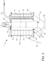
- the reactor 7 of the pyrolytic gasifier 2 is shown in greater detail in Figure 3 .
- the reactor 7 comprises a reaction chamber 17 in which the biomass 6 is gasified in the presence of a given amount of air (sub-stoichiometric).
- the reactor 7 further comprises an outer coating 71 with respect to said reaction chamber 17.
- Said reaction chamber 17 has truncated-cone shape and is advantageously made of a polycrystalline alumina fiber-based material.
- said material comprises at least 70% by weight of polycrystalline alumina, preferably at least 75% by weight, more preferably at least 80% by weight, for example about 90% by weight.
- said material further comprises at least 5% by weight of silica, preferably between 10% and 30% by weight of silica, more preferably between 10% and 25% by weight of silica, even more preferably between 10% and 20% by weight of silica.
- said material has a density comprised between 350 and 500 kg/m 3 .
- said polycrystalline alumina fiber-based material is produced by the company Unifrax under the trade name High Temperature Saffil ® Rigiform TM .
- said material is produced by the company Unifrax under the trade name Saffil ® 160 HD.
- the reaction chamber 17 has an upper surface 72 and a lower surface 73, wherein the diameter of the upper surface 72 is slightly smaller than the diameter of the lower surface 73 in order to give an adequate draft angle, e.g., about 4°, to the inner surface of the reaction chamber 17.
- the diameter of the upper surface 72 is comprised between 70 and 90 mm and the diameter of the lower surface 73 is comprised between 100 and 120 mm. Said geometry of the reaction chamber 17 facilitates the downward flow of the biomass 6.
- Said outer coating 71 has an annular shape and is advantageously made of a microporous insulating material.
- the latter preferably comprises silica, for example powder or reinforcing filaments of pyrogenic silica, to which opacifiers and/or inorganic oxides may be added.
- said microporous insulating material is produced by the company Promat under the trade name Promalight ® , or by the company Bifire under the trade name Microbifire ® , or by the company Unifrax under the trade name Excelfrax ® .
- Said outer coating 71 consists of a plurality of overlapping rings 74 made of said microporous insulating material, which guarantee the thermal insulation of the reactor 7.
- the reactor 7 further comprises a layer 75 of said polycrystalline alumina fiber-based material having varying thickness interposed between the reaction chamber 17 and the outer coating 71.
- the reaction chamber 17 and the layer 75 of the polycrystalline alumina fiber-based material form a monolithic structure.
- said monolithic structure is sealed on top with the structure by means of a rubber gasket 76; on the bottom, instead, given the high working temperature, it is sealed by means of a polycrystalline alumina fiber-based gasket 77.
- the hopper 14 shown in Figures 2 and 3 comprises an upper frame (or edge) 78 adapted to support the outer coating 71 through an appropriate support plate 79, preferably annular.
- an insulating plate 80 which is also preferably annular, made, e.g., with biosoluble refractory fibers, is placed above said support plate 79; said plate 80 ensures the thermal break with the support plate 79 and thus with the hopper 14, as well as an airtight seal.
- Both the hopper 14 and the support plate 79 are advantageously made of stainless steel.
- Said hopper 14 further comprises a lip 81, which projects below said frame 78 and defines a support base for the reaction chamber 17 through which the hopper 14 itself receives the produced syngas 8.
- Said geometry allows creating an annular volume in the upper part of the hopper 14 through which the syngas 8 is sucked into the duct 13.
- the syngas feeding duct 13 has a gasket at the interface with the support plate 79 consisting of polycrystalline alumina fiber-based rings 82.
- the hopper 14 is advantageously insulated from the unloading auger 12 by means of an element 83 made of said microporous insulating material.
- a first valve 22 separating the biomass 6 (shown in Figures 2 and 3 ) is placed at the inlet interface of the biomass 6 in the reactor 7, in particular above the buffer 20.
- a second valve 23 separating the biochar 9 (shown in Figure 2 ) is positioned at the outlet interface of the biochar 9 from the unloading auger 12.
- the separation valve 22 of the biomass 6 is opened at the process start-up and allows the inflow of biomass 6 and air into the reactor 7.
- the air supply although limited, is necessary to support the gasification process by providing heat through the combustion of a small portion of the biomass 6 and the produced syngas 8.
- the separation valve 23 of the biochar 9 is opened whenever it is necessary to expel the biochar 9, thus operating discontinuously.
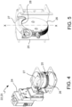
- Said separation valves 22, 23 are butterfly valves and are shown in more detail in Figures 4 and 5 .
- the valve 22, 23 shown in Figure 4 is in the fully closed position, while the valve 22, 23 shown in Figure 5 is in the fully open position.
- the valve 22, 23 according to the embodiment of Figure 4 comprises an actuator 24, a cylindrical valve body 25, a plate-like shutter 26 and an insert 27 shaped as an arc of circumference.
- the plate-like shutter 26 assumes a position parallel to the longitudinal axis X-X of the cylindrical valve body 25 and the insert 27 adheres to a portion 28 of the edge of the shutter 26 which would otherwise come into contact with the biomass 6 or with the biochar 9.
- the gap between the valve body 25 and the shutter 26 is filled along the longitudinal axis X-X of the valve body 25, preventing the biomass 6 and the biochar 9 from settling on the edge of the shutter 26, clogging the valve 22, 23 and preventing the proper closing of the valve itself. Therefore, the insert 27 fulfills the function of protecting the seal of the plate-like shutter 26 when the valve 22, 23 is in the fully open position.
- the gasifier 2 is of the “downdraft” (i.e., the biomass 6 flows downward and the syngas 8 produced transits in the same direction) "open core” (i.e., with air supply from above along with the biomass) type.
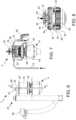
- Figures 6-10 illustrate the assembly consisting of the burner 3 and the Stirling engine 4.
- the burner 3 comprises:
- pre-mixing flanges 35 allow partial cooling of the fuel syngas 8 by means of the combustion air 31.
- the Stirling engine 4 comprises a high-temperature heat exchanger 38 (so-called “hot exchanger") shown in Figures 7, 8 , 10 , a low-temperature heat exchanger (so-called “cold exchanger”), a regenerator and an electric generator 39.
- the cold exchanger and the regenerator are not visible in the figures.
- the hot exchanger 38 of the Stirling engine is inserted inside the combustion chamber 30.
- a tubular element 40 Downstream of the hot exchanger 38 of the Stirling engine, a tubular element 40 is placed, also indicated as a cooling ring, inside which a cooling fluid flows, so that heat transfer downstream of said hot exchanger 38 is prevented.
- the cooling ring 40 performs the thermal break function between the burner 3 and the Stirling engine 4, preventing unwanted heat from entering the part of the Stirling engine 4 under the hot exchanger 38 and safeguarding the underlying components from excessive heating.
- the combustion chamber 30 of the burner 3 consists of a cylinder which integrates connections for the feeding duct 13 of the fuel syngas 8 coming from the gasifier 2 and for the feeding duct 41 of the combustion air 31. Furthermore, the combustion chamber 30 integrates the attachment flange 42 to the Stirling engine 4 and the attachment flange 43 to the exhaust system 33.
- a bell 44 and a means 45 made of porous ceramic material are placed inside the combustion chamber 30 of the burner 3.
- Said bell 44 is open at the bottom and houses the hot exchanger 38 of the Stirling engine inside.
- said hot exchanger 38 is inserted from the open bottom of the bell 44.
- Said bell 44 is such to convey the hot combustion gases 32 into the hot exchanger 38, where they undergo heat exchange providing heat and generating exhaust fumes 34 (or combustion fumes 34).
- said bell 44 constrains the hot combustion gases 32 to flow through the entire hot exchanger 38 with minimal heat dissipation to the outside, thus optimizing the heat exchange with the Stirling engine 4.
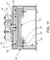
- Said bell 44 comprises steel walls internally lined with a refractory insulating material, as further described below with reference to Figure 11 .
- the aforementioned nozzle or duct 36 may be replaced by a hole made in said refractory insulating material, such as to convey the fuel syngas 8 and the combustion air 31 inside the combustion chamber 30.
- the porous ceramic means 45 is housed in the upper part of the bell 44 above the hot exchanger 38 and is supported at least partially by the refractory insulating material of the bell 44. Said porous ceramic means 45 is an optimized combustion volume in which the syngas 8 is combusted in the presence of combustion air 31 generating hot combustion gases 32 ( Figure 8 ). Furthermore, the porous means 45 allows a homogeneous temperature distribution, ensuring optimal heat exchange with the Stirling engine 4 and low polluting emissions.
- the bell 44 is open at the bottom and the hot exchanger of the Stirling engine is inserted in its inside (not shown in Figure 11 ).
- Said bell 44 is delimited by an upper wall 47 and side walls 48.
- Said walls 47, 48 are made of steel and are internally lined with a refractory insulating material, e.g., based on polycrystalline alumina fiber.
- a refractory insulating material e.g., based on polycrystalline alumina fiber.
- said material is produced by the company Schupp under the trade name ITM-Fibermax ® , preferably Blanket 1600-130.
- the upper steel wall 47 is internally coated with a layer 49 of polycrystalline alumina fiber-based material.
- said layer 49 is further coated, at its ends, with two layers 50 of polycrystalline alumina fiber-based material, which act as spacers defining a space 51 interposed therebetween for the passage of the mixture 37 of syngas and combustion air exiting the nozzle 36.
- Said layers 50 can have variable thickness and size; consequently, the space 51 interposed therebetween has variable thickness and inner diameter as well.
- the steel side walls 48 are internally coated with first layers 52 of polycrystalline alumina fiber having a given thickness and with second layers 53 of polycrystalline alumina fiber having a different thickness, in this case a greater thickness.
- the porous ceramic means 45 is housed between said layers 52 of insulating material. Consequently, by means of said layers 52, the porous ceramic means 45 is thermally insulated from the bell 44.
- the porous ceramic material from which the means 45 is made is produced by the company Lanik under the trade name Vukopor ® S or Vukopor ® HT.
- the bell 44 comprises an additional element 54 made of refractory insulating material, e.g., based on polycrystalline alumina fiber, immediately below the porous ceramic means 45, such as to prevent unwanted entry of heat through the top of the Stirling engine below.
- Said element 54 mimics the shape of the upper dome of the hot exchanger 38 of the Stirling engine, visible in Figures 7, 8 , 10 .
- the exhaust system 33 mentioned above receives the combustion fumes 34 exiting the hot exchanger 38 of the Stirling engine 4, once the latter have traveled upward through the gap 46 present between the combustion chamber 30 and the bell 44.
- Said exhaust system 33 comprises an exhaust 55 from which combustion fumes 34 escape, a heat exchanger 56 connected to said exhaust 55 for recovering heat from the exhaust fumes 34 ( Figure 10 ), a lambda probe 57 which provides a signal based on which the air-syngas ratio at the inlet of burner 3 is adjusted ( Figures 6 , 10 ), and a thermocouple 58 which measures the temperature of the combustion fumes 34 ( Figures 6 , 10 ).
- An extraction fan 59 (shown in Figures 6 and 10 ) of the combustion fumes 34 is connected to said heat exchanger 56, by virtue of which the combustible syngas 8 from the gasifier 2 and the combustion air 31 are sucked inside the combustion chamber 30.
- Said extraction fan 59 has variable speed.
- the micro-generator 1 is equipped with an electronic control, which manages the operation of the machine through the installed sensors and actuators and is independently powered by on-board batteries so that it can be safely shut down even in case the external electrical connection is interrupted. To be able to start up, the micro-generator 1 checks for the presence of the external power grid (both "on-grid” and “off-grid” via inverter).
- the pyrolytic gasification process is started by means of the electric heater 18, which brings the biomass 6 to the gasification temperature, e.g., about 900°C.
- the separation valve 22 of the biomass 6 is opened.
- the extraction fan 59 is activated with a speed proportional to the temperature of the electric heater 18.
- the biomass 6 is fed into the reactor 7 of the pyrolytic gasifier 2, through the inlet 11, by means of the loading auger 10.
- the biomass loading auger 10 is started; when the filling level of the buffer 20 is above said threshold, the biomass loading auger 10 is stopped and the feeding of the biomass 6 to the reactor is interrupted.
- reaction front advances from the bottom to the top where biomass 6 not yet gasified is located.
- thermocouple 19 keeps the temperature of the upper part of the reaction chamber 17 monitored; when the integral over time of the temperature measured by thermocouple 19 exceeds a given threshold value of said integral, the separation valve 23 of the biochar 9 is opened, the unloading auger 12 is started and part of the biochar 9 is extracted. In this manner, the reacting biomass 6 is made to flow downward and along with it the reaction front as well, which remains confined to the reaction zone delimited between the thermocouple 19 and the electric heater 18.
- the gasifier 2 once fully operational, works with a slow and intermittent flow of biomass 6 such as to maintain the reaction front within the aforementioned reaction zone.
- the extraction fan 59 By operating the extraction fan 59, the system consisting of the gasifier 2 and the burner 3 is depressurized and the inflows of fuel syngas 8 from the gasifier 2 to the burner 3 and of air to both the gasifier 2 and the burner 3 are adjusted.
- the extraction fan 59 By operating the extraction fan 59, the combustion fumes 34 are extracted which travel upward through the gap 46 between the combustion chamber 30 and the bell 44, creating a vacuum inside the burner 3. In turn, the fuel syngas 8 exiting the gasifier 2 and the combustion air 31 are sucked into the combustion chamber 30 of the burner, respectively, through the supply ducts 13 and 41. In turn, air is sucked into the gasifier 2.
- the fuel syngas 8 and the combustion air 31 are sucked inside the combustion chamber 30 passing through the pre-mixing flanges 35, then the nozzle 36, until they arrive inside the porous ceramic means 45, which defines the volume in which the combustion takes place with the generation of the hot combustion gases 32.
- the hot combustion gases 32 are subjected to heat exchange within the hot exchanger 38 of the Stirling engine 4, from which heat is recovered that puts the electric generator 39 in oscillation, thus obtaining the aforementioned combustion fumes 34 resulting from said heat exchange.
- the combustion fumes 34 are extracted through the extraction fan 59. Said combustion fumes 34 travel upward through the cavity 46 present between the combustion chamber 30 and the bell 44, pass through the exhaust 55 on which the lambda probe 57 and the thermocouple 58 are placed, then they are fed to the heat exchanger 56 for recovery of the heat contained therein.
- the lambda probe 57 adjusts the air-syngas ratio accurately by virtue of the valve 60 located on the inlet duct 41 of the combustion air 31, adjusting the pressure drop and thus the inflow. More specifically, the lambda probe 57 provides a signal based on which the aforementioned air-syngas ratio is accurately adjusted.
Landscapes
- Engineering & Computer Science (AREA)
- Mechanical Engineering (AREA)
- General Engineering & Computer Science (AREA)
- Combustion & Propulsion (AREA)
- Chemical & Material Sciences (AREA)
- Thermal Sciences (AREA)
- Physics & Mathematics (AREA)
- Environmental & Geological Engineering (AREA)
- Life Sciences & Earth Sciences (AREA)
- Sustainable Development (AREA)
- Sustainable Energy (AREA)
- Processing Of Solid Wastes (AREA)
- Diaphragms For Electromechanical Transducers (AREA)
- Other Liquid Machine Or Engine Such As Wave Power Use (AREA)
- Telephone Function (AREA)
Claims (16)
- Verfahren einer Kraft-Wärme-Kopplung elektrischer Energie und Wärme, welches von einer erneuerbaren und nachhaltigen Energiequelle (6) startet, bevorzugt einer holzartigen Biomasse, in einem Mikro-Blockheizkraftwerk (1), welches einen pyrolytischen Vergaser (2), einen Brenner (3) und einen Stirlingmotor (4) umfasst, wobei das Verfahren die folgenden Schritte umfasst:i) Zuführen der Energiequelle (6) zu dem pyrolytischen Vergaser (2), welcher eine Reaktionskammer (17) umfasst, innerhalb welcher die Energiequelle (6) reagiert, wodurch Synthesegas (8) und Biokohle (9) erzeugt wird;ii) Zuführen des Synthesegases (8), welches während des Schritts (1) erzeugt wird, zu dem Brenner (3), welcher eine Verbrennungskammer (30) umfasst, innerhalb welcher das Synthesegas (8) in der Anwesenheit von Verbrennungsluft (31) verbrannt wird, wodurch heiße Verbrennungsgase (32) erzeugt werden;iii) Aussetzen einem Wärmeaustausch der heißen Verbrennungsgase (32) in einem Wärmeaustauscher (38), einem sogenannten "heißen Austauscher", des Stirlingmotors (4), welcher dazu angepasst ist, elektrische Energie zu erzeugen, wobei Abgase (34) erhalten werden, welche von dem Wärmeaustausch stammen,wobei, während des Schritts ii), das Verhältnis Verbrennungsluft (31) zu Synthesegas (8) auf Grundlage eines Signals angepasst wird, welches durch eine Lambdasonde (57) bereitgestellt ist, welche von einem Fluss der Abgase (34) durchkreuzt wird, mittels eines Ventils (60), welches an einer Einlassdurchführung (41) der Verbrennungsluft (31) angeordnet ist,wobei das Verfahren eine Hochlaufphase des Mikro-Blockheizkraftwerks (1) und eine Vollbetriebsphase (Stabilitätsphase) umfasst, welche auf die Hochlaufphase folgt, und dadurch gekennzeichnet ist, dass die Hochlaufphase einen ersten Schritt a) eines Detektierens der Anwesenheit von Synthesegas (8) innerhalb des Brenners (3) und einen darauffolgenden Schritt b) eines Zündens des Brenners (3) umfasst, wobei:der erste Schritt a) ein Berechnen des Zeitintegrals der Temperatur der Reaktionskammer (17) des pyrolytischen Vergasers (2) und ein Berechnen des Zeitintegrals des Wertes umfasst, welcher durch die Lambdasonde (57) gelesen wird, wobei, während des Schritts a), der berechnete Wert des Zeitintegrals der Temperatur der Reaktionskammer (17) mit einem vorfestgesetzten Schwellenwert des Integrals, dem sogenannten ersten Schwellenwert, verglichen wird, und, wenn der erste Schwellenwert überschritten wird, der berechnete Wert des Zeitintegrals des Wertes, welcher durch die Lambdasonde (57) gelesen wird, mit einem vorfestgesetzten Schwellenwert des Integrals, dem sogenannten zweiten Schwellenwert, verglichen wird, bis er überschritten wird, wobei die Überschreitung des zweiten Schwellenwerts eine Anzeichen für die Anwesenheit von Synthesegas (8) und die wesentliche Abwesenheit von Luft (31) innerhalb des Brenners (3) ist,wobei der zweite Schritt b) gestartet wird, wenn der zweite Schwellenwert überschritten wird, und eine erhöhte Zufuhr von Verbrennungsluft (31) in die Verbrennungskammer (30) des Brenners (3) umfasst, bis zu der Zündung einer Flamme.
- Verfahren nach Anspruch 1, welches das Erzeugen eines Zündungsfunkens der Flamme in dem Schritt b) umfasst oder die Erzeugung eines Zündungsfunkens der Flamme zu Beginn der Hochlaufphase umfasst.
- Verfahren nach Anspruch 1 oder 2, wobei die Hochlaufphase einen Schritt c) eines Detektierens der Anwesenheit der Flamme in der Verbrennungskammer (30) des Brenners (3) umfasst, wobei, in dem Schritt c), die Ableitung nach Zeit der Temperatur der Verbrennungskammer (30) mit einem vorfestgesetzten Schwellenwert der Ableitung verglichen wird, wobei das Überschreiten davon ein Anzeichen der Anwesenheit der Flamme ist.
- Verfahren nach einem der vorhergehenden Ansprüche, wobei die Stabilitätsphase durch einen niedrigeren Wert, welcher durch die Lambdasonde gelesen wird, d.h., ein höheres Verhältnis von Verbrennungsluft (31) zu Synthesegas (8), als die Hochlaufphase gekennzeichnet ist, und wobei die Stabilitätsphase zu dem Ende des Schritts c) gestartet wird.
- Verfahren nach einem der vorhergehenden Ansprüche, wobei, während des Schritts ii), das Synthesegas (8), welches den pyrolytischen Vergaser (2) verlässt, in die Verbrennungskammer (30) des Brenners (3) mittels der Anwesenheit eines Vakuums gesaugt wird, welches durch ein geeignetes Absauggebläse (59) für das Absaugen der Abgase (34) erzeugt wird, und wobei, während der Hochlaufphase, das Absauggebläse (59) mit einer Geschwindigkeit aktiv ist, welche proportional zu der Temperatur der Reaktionskammer (17) des pyrolytischen Vergasers (2) ist.
- Verfahren nach Anspruch 5, wobei:während der Stabilitätsphase, die elektrische Leistung des Mikro-Blockheizkraftwerks (1) mit einer elektrischen Zielleistung verglichen wird, wodurch ein Leistungsdelta erhalten wird, und wobei, währen der Stabilitätsphase, die Geschwindigkeit des Absauggebläses (59) in Funktion des erhaltenen Leistungsdeltas erhöht oder verringert wird, oderwährend der Stabilitätsphase, die Temperatur des Brenners mit einer Zieltemperatur verglichen wird, wodurch ein Temperaturdelta erhalten wird, und die Geschwindigkeit des Absauggebläses in Funktion des Temperaturdeltas erhöht oder verringert wird.
- Verfahren nach einem der vorhergehenden Ansprüche, wobei, während sowohl der Hochlaufphase als auch der Stabilitätsphase, die Energiequelle (6) dem pyrolytischen Vergaser (2) durch eine Ladeförderschnecke (10) zugeführt wird, wobei die Ladeförderschnecke (10) jedes Mal gestartet wird, wenn der Füllpegel eines Verbindungselements (20) zwischen der Ladeförderschnecke (10) und dem Einlass (11) der Reaktionskammer (17) des pyrolytischen Vergasers (2) unter einem vorfestgesetzten Schwellenwert ist, wobei das Fülllevel durch einen geeigneten Sensor (21) detektiert wird.
- Verfahren nach einem der vorhergehenden Ansprüche, wobei die Reaktionskammer (17) des pyrolytischen Vergasers (2) auf eine Vergasungstemperatur gebracht wird, bevorzugt zwischen 1000°C und 1200°C, bei welcher die Energiequelle (6) reagiert, wodurch Synthesegas (8) und Biokohle (9) erzeugt werden,wobei die Reaktionsfront der Energiequelle (6) zwischen einer oberen Grenze und einer unteren Grenze umfasst ist,wobei die Energiequelle (6) unter Reaktion von der Biokohle (9) unterstützt wird, welche innerhalb des pyrolytischen Vergasers (2) akkumuliert wird, solang das Zeitintegral der Temperatur der oberen Grenze der Reaktionsfront einen vorfestgesetzten Schwellenwert des Integrals nicht überschreitet, und, wenn der Schwellenwert überschritten wird, die Biokohle (9) wenigstens teilweise durch eine Entladeförderschnecke (12) abgeführt wird, wodurch verursacht wird, dass die Reaktionsfront abgesenkt wird, sodass sie zwischen der oberen Grenze und der unteren Grenze umfasst ist.
- Mikro-Blockheizkraftwerk (1), umfassend:einen pyrolytischen Vergaser (2), welcher dazu angepasst ist, Synthesegas (8) und Biokohle (9) aus einer erneuerbaren und nachhaltigen Energiequelle (6) zu produzieren, bevorzugt aus holzartiger Biomasse,einen Brenner (3), welcher dazu angepasst ist, das Synthesegas (8), welches durch den pyrolytischen Vergaser (2) produziert ist, aufzunehmen und heiße Verbrennungsgase (32) zu erzeugen,einen Stirlingmotor (4), welcher einen Wärmeaustauscher (38) umfasst, einen sogenannten "heißen Austauscher", welchem die heißen Verbrennungsgase (32) zugeführt werden, wobei der Stirlingmotor (4) dazu angepasst ist, elektrische Energie zu erzeugen,ein Abgassystem (33), welches dazu angepasst ist, Abgase (34) zu empfangen, welche den heißen Austauscher (38) des Stirlingmotors (4) verlassen,wobei das Abgassystem (33) einen Austauscher (56) für die Rückgewinnung der Wärme von den Abgasen (34), eine Lambdasonde (57), welche ein Signal bereitstellt, auf Grundlage welchem das Verhältnis von Luft (31) zu Synthesegas (8) an dem Einlass des Brenners (3) angepasst wird, und einen Temperaturfühler (58) umfasst, welcher die Temperatur der Abgase (34) misst,wobei der Brenner (3) umfasst:eine Verbrennungskammer (30), innerhalb welcher das Synthesegas (8) in Anwesenheit von Verbrennungsluft (31) verbrannt wird,Vormischflansche (35) für das Synthesegas (8) und die Verbrennungsluft (31), stromaufwärts der Verbrennungskammer (30),ein Mittel, stromabwärts der Vormischflansche (35), welches dazu angepasst ist, das Synthesegas (8) und die Luft (31) in die Verbrennungskammer (30) zu befördern, wobei das Mittel bevorzugt eine Düse oder eine Durchführung (36) ist,wobei das Mikro-Blockheizkraftwerk (1) dadurch gekennzeichnet ist, dass die Verbrennungskammer (30) umfasst:eine Glocke (44), welche an dem Boden offen ist, innerhalb welcher der heiße Austauscher (38) des Stirlingmotors (4) untergebracht ist, wobei die Glocke (44) dazu angepasst ist, die heißen Verbrennungsgase (32) in den heißen Austauscher (38) zu befördern, und Stahlflächen (47, 48) umfasst, welche innen, wenigstens teilweise, mit einem hitzebeständigen isolierenden Material (49, 50, 52, 53) beschichtet sind,ein Element (45), welches aus einem porösen Keramikmaterial gefertigt ist, welches in dem oberen Teil der Glocke (44) oberhalb des heißen Austauschers (38) des Stirlingmotors (4) untergebracht ist, wobei das Element (45), welches aus einem porösen Keramikmaterial gefertigt ist, wenigstens teilweise durch das hitzebeständige isolierende Material (50, 52) getragen ist, und ein optimiertes Verbrennungsvolumen repräsentiert, innerhalb welchem das Synthesegas (8) in der Anwesenheit von Verbrennungsluft (31) verbrannt wird.
- Mikro-Blockheizkraftwerk (1) nach Anspruch 9, wobei die Glocke (44) durch einen Zylinder, welcher an dem Boden offen ist, welcher eine obere Fläche und eine Seitenfläche umfasst, oder durch ein Parallelepiped gebildet ist, welches an dem Boden offen ist, welches eine obere Fläche (47) und vier Seitenflächen (48) umfasst, wobei die Flächen aus Stahl gefertigt sind und innen, wenigstens teilweise, mit einem hitzebeständigen isolierenden Material (49, 50, 52, 53) beschichtet sind.
- Mikro-Blockheizkraftwerk (1) nach Anspruch 9 oder 10, wobei die Verbrennungskammer (30) ein weiteres Element (54) umfasst, welches aus einem hitzebeständigen isolierenden Material gefertigt ist, wobei das Element (54) zwischen dem Element (45), welches aus einem porösen Keramikmaterial gefertigt ist, und dem heißen Austauscher (38) des Stirlingmotors (4) eingefügt ist.
- Mikro-Blockheizkraftwerk (1) nach einem der Ansprüche 9 bis 11, wobei das hitzebeständige isolierende Material ein polykristallines faserbasiertes Aluminiumoxidmaterial ist, welches wenigstens 70 Gew.-% polykristallines Aluminiumoxid umfasst, und/oder das poröse Material Siliziumkarbid, Aluminiumoxid und Siliziumoxid umfasst.
- Mikro-Blockheizkraftwerk (1) nach einem der Ansprüche 9 bis 12, welches einen Kühlungsring (40) umfasst, stromabwärts des heißen Austauschers (38) des Stirlingmotors (4), innerhalb welchem ein Kühlungsfluid fließt, wobei der Kühlungsring (40) dazu angepasst ist, die thermische Übertragung stromabwärts des heißen Austauschers (38) zu verhindern.
- Mikro-Blockheizkraftwerk (1) nach einem der Ansprüche 9 bis 13, wobei die Abgase (34), welche den heißen Austauscher (38) des Stirlingmotors (4) verlassen, durch ein Fortbewegen aufwärts in einen Spalt (46) abgeführt werden, welcher zwischen der Glocke (44) und der Verbrennungskammer (30) vorzufinden ist.
- Mikro-Blockheizkraftwerk (1) nach Anspruch 14, welches ein Absauggebläse (59) umfasst, welcher mit dem Austauscher (56) zu der Rückgewinnung von Wärme von den Abgasen (34) verbunden ist, wobei das Absauggebläse (59) derart beschaffen ist, um die Abgase (34) abzusaugen, wodurch ein Vakuum innerhalb des Brenners (3) erzeugt wird, und um wiederum das Einströmen des Synthesegases (8), welches von dem Vergaser (2) kommt, und der Verbrennungsluft (31) in den Brenner (3) selbst anzupassen.
- Mikro-Blockheizkraftwerk (1) nach einem der Ansprüche 9 bis 15, wobei der pyrolytische Vergaser (2) umfasst:einen Reaktor (7), welcher eine Reaktionskammer (17), in welcher die Energiequelle (6) in der Anwesenheit von Luft vergast wird, wodurch Synthesegas (8) und Biokohle (9) erzeugt wird, ein elektrisches Heizelement (18), welches dazu angepasst ist, die Reaktionskammer (17) auf die Vergasungstemperatur zu erwärmen, und ein Thermoelement (19) umfasst, welcher dazu angepasst ist, die Temperatur in dem oberen Teil der Reaktionskammer (17) zu überwachen, wobei die Reaktionsfront zwischen dem Heizelement (18) und dem Thermoelement (19) umfasst ist,eine Ladeförderschnecke (10) für ein Zuführen der erneuerbaren Quelle (6) in den Reaktor (7),ein Verbindungselement (20) zwischen der Ladeförderschnecke (10) und dem Reaktor (7), welches mit einem Sensor (21) bereitgestellt ist, welcher dazu angepasst ist, den bestehenden Pegel der erneuerbaren Quelle (6) in seinem inneren zu detektieren,eine Entladeförderschnecke (12) für das Abführen der Biokohle (9),einen Trichter (14), welcher den Reaktor (7) und die Entladeförderschnecke (12) verbindet, wobei der Trichter (14) ein Sammelvolumen des Synthesegases (8) bildet, welches in dem Reaktor (7) produziert wird,eine Verbindungsdurchführung (13) zwischen dem Trichter (14) und dem Brenner (3), von welchem das Synthesegas (8) abgesaugt wird und dem Brenner (3) zugeführt wird.
Applications Claiming Priority (2)
| Application Number | Priority Date | Filing Date | Title |
|---|---|---|---|
| IT102021000016703A IT202100016703A1 (it) | 2021-06-25 | 2021-06-25 | Processo di cogenerazione e relativo apparato |
| PCT/IB2022/055875 WO2022269554A1 (en) | 2021-06-25 | 2022-06-24 | Cogeneration process and related apparatus |
Publications (3)
| Publication Number | Publication Date |
|---|---|
| EP4359653A1 EP4359653A1 (de) | 2024-05-01 |
| EP4359653C0 EP4359653C0 (de) | 2025-03-19 |
| EP4359653B1 true EP4359653B1 (de) | 2025-03-19 |
Family
ID=77802048
Family Applications (1)
| Application Number | Title | Priority Date | Filing Date |
|---|---|---|---|
| EP22741848.0A Active EP4359653B1 (de) | 2021-06-25 | 2022-06-24 | Kogenerationsverfahren und zugehörige vorrichtung |
Country Status (3)
| Country | Link |
|---|---|
| EP (1) | EP4359653B1 (de) |
| IT (1) | IT202100016703A1 (de) |
| WO (1) | WO2022269554A1 (de) |
Family Cites Families (4)
| Publication number | Priority date | Publication date | Assignee | Title |
|---|---|---|---|---|
| JP2005274123A (ja) * | 2004-02-27 | 2005-10-06 | Ecomeet Solutions Co Ltd | 発電システム及びその制御方法 |
| US7906695B2 (en) | 2004-10-25 | 2011-03-15 | Res/Op Technologies Inc. | Biomass conversion by combustion |
| DE102006001299A1 (de) | 2006-01-11 | 2007-07-12 | Eckhart Weber | Holzpellet-Blockheizkraftwerk mit Stirlingmotor in Brennwerttechnik |
| GB201107855D0 (en) * | 2011-05-11 | 2011-06-22 | Anglia Ruskin University | Gasifier |
-
2021
- 2021-06-25 IT IT102021000016703A patent/IT202100016703A1/it unknown
-
2022
- 2022-06-24 WO PCT/IB2022/055875 patent/WO2022269554A1/en not_active Ceased
- 2022-06-24 EP EP22741848.0A patent/EP4359653B1/de active Active
Also Published As
| Publication number | Publication date |
|---|---|
| WO2022269554A1 (en) | 2022-12-29 |
| EP4359653A1 (de) | 2024-05-01 |
| EP4359653C0 (de) | 2025-03-19 |
| IT202100016703A1 (it) | 2022-12-25 |
Similar Documents
| Publication | Publication Date | Title |
|---|---|---|
| JP5120823B1 (ja) | 廃棄物ガス化溶融炉 | |
| US4840129A (en) | Pyrolysis system | |
| CN201992624U (zh) | 热效率提高的燃烧设备 | |
| WO1999031202A1 (fr) | Systeme de gazeification de combustible | |
| EP3324116B1 (de) | Rauchlose verbrennungsanlage und system damit | |
| KR20070048149A (ko) | Igcc 시스템에서 석탄가스화 방법과 장치 | |
| KR101689917B1 (ko) | 시일을 갖는 가스화 냉각 시스템 | |
| KR101921225B1 (ko) | 폐기물 용융로 | |
| JP2012001649A (ja) | フィルタの再生方法、及びこの方法が適用されるガス化発電プラント | |
| EP4359653B1 (de) | Kogenerationsverfahren und zugehörige vorrichtung | |
| FR2531944A1 (fr) | Appareil de reforming de combustible a base d'hydrocarbure en un gaz riche en hydrogene | |
| JP2008063363A (ja) | ガス化炉及びガス化炉システム | |
| US12467620B2 (en) | Downward mobile gasification boiler for surface gas phase combustion and pyrolysis of biomass briquette | |
| WO2013058253A1 (ja) | ガスタービン発電プラントの制御方法、ガスタービン発電プラント、炭素含有燃料ガス化炉の制御方法及び炭素含有燃料ガス化炉 | |
| EP4359654B1 (de) | Mikro-kogenerator | |
| CN113310055A (zh) | 生活垃圾蓄热裂解气化系统 | |
| TW201418444A (zh) | 用於在焦爐組中產生多個蒸汽流或熱水流之設備及方法 | |
| Zhuikov et al. | Experience of using synthetic gas as the main fuel in an industrial heating boiler house | |
| CN102031151B (zh) | 防结渣生物质气化燃烧器 | |
| ITMI20110045A1 (it) | Impianto di termovalorizzazione multiuso di fanghi biologici rifiuti organici e biomasse minuti | |
| JPH0559954B2 (de) | ||
| GB2492791A (en) | Annular gasification inlet | |
| JP6824685B2 (ja) | バーナ装置、バーナ装置の冷却媒体制御方法 | |
| WO2011013017A1 (en) | A plant for molecular dissociation of waste material | |
| CN115574326A (zh) | 一种可燃垃圾等离子焚烧炉系统及使用方法 |
Legal Events
| Date | Code | Title | Description |
|---|---|---|---|
| STAA | Information on the status of an ep patent application or granted ep patent |
Free format text: STATUS: UNKNOWN |
|
| STAA | Information on the status of an ep patent application or granted ep patent |
Free format text: STATUS: THE INTERNATIONAL PUBLICATION HAS BEEN MADE |
|
| PUAI | Public reference made under article 153(3) epc to a published international application that has entered the european phase |
Free format text: ORIGINAL CODE: 0009012 |
|
| STAA | Information on the status of an ep patent application or granted ep patent |
Free format text: STATUS: REQUEST FOR EXAMINATION WAS MADE |
|
| 17P | Request for examination filed |
Effective date: 20231220 |
|
| AK | Designated contracting states |
Kind code of ref document: A1 Designated state(s): AL AT BE BG CH CY CZ DE DK EE ES FI FR GB GR HR HU IE IS IT LI LT LU LV MC MK MT NL NO PL PT RO RS SE SI SK SM TR |
|
| DAV | Request for validation of the european patent (deleted) | ||
| DAX | Request for extension of the european patent (deleted) | ||
| GRAP | Despatch of communication of intention to grant a patent |
Free format text: ORIGINAL CODE: EPIDOSNIGR1 |
|
| STAA | Information on the status of an ep patent application or granted ep patent |
Free format text: STATUS: GRANT OF PATENT IS INTENDED |
|
| INTG | Intention to grant announced |
Effective date: 20241011 |
|
| GRAS | Grant fee paid |
Free format text: ORIGINAL CODE: EPIDOSNIGR3 |
|
| GRAA | (expected) grant |
Free format text: ORIGINAL CODE: 0009210 |
|
| STAA | Information on the status of an ep patent application or granted ep patent |
Free format text: STATUS: THE PATENT HAS BEEN GRANTED |
|
| AK | Designated contracting states |
Kind code of ref document: B1 Designated state(s): AL AT BE BG CH CY CZ DE DK EE ES FI FR GB GR HR HU IE IS IT LI LT LU LV MC MK MT NL NO PL PT RO RS SE SI SK SM TR |
|
| REG | Reference to a national code |
Ref country code: GB Ref legal event code: FG4D |
|
| REG | Reference to a national code |
Ref country code: CH Ref legal event code: EP |
|
| REG | Reference to a national code |
Ref country code: IE Ref legal event code: FG4D |
|
| REG | Reference to a national code |
Ref country code: DE Ref legal event code: R096 Ref document number: 602022012032 Country of ref document: DE |
|
| U01 | Request for unitary effect filed |
Effective date: 20250414 |
|
| U07 | Unitary effect registered |
Designated state(s): AT BE BG DE DK EE FI FR IT LT LU LV MT NL PT RO SE SI Effective date: 20250422 |
|
| U20 | Renewal fee for the european patent with unitary effect paid |
Year of fee payment: 4 Effective date: 20250523 |
|
| PG25 | Lapsed in a contracting state [announced via postgrant information from national office to epo] |
Ref country code: RS Free format text: LAPSE BECAUSE OF FAILURE TO SUBMIT A TRANSLATION OF THE DESCRIPTION OR TO PAY THE FEE WITHIN THE PRESCRIBED TIME-LIMIT Effective date: 20250619 |
|
| PG25 | Lapsed in a contracting state [announced via postgrant information from national office to epo] |
Ref country code: NO Free format text: LAPSE BECAUSE OF FAILURE TO SUBMIT A TRANSLATION OF THE DESCRIPTION OR TO PAY THE FEE WITHIN THE PRESCRIBED TIME-LIMIT Effective date: 20250619 |
|
| PG25 | Lapsed in a contracting state [announced via postgrant information from national office to epo] |
Ref country code: HR Free format text: LAPSE BECAUSE OF FAILURE TO SUBMIT A TRANSLATION OF THE DESCRIPTION OR TO PAY THE FEE WITHIN THE PRESCRIBED TIME-LIMIT Effective date: 20250319 |
|
| PG25 | Lapsed in a contracting state [announced via postgrant information from national office to epo] |
Ref country code: GR Free format text: LAPSE BECAUSE OF FAILURE TO SUBMIT A TRANSLATION OF THE DESCRIPTION OR TO PAY THE FEE WITHIN THE PRESCRIBED TIME-LIMIT Effective date: 20250620 |
|
| PG25 | Lapsed in a contracting state [announced via postgrant information from national office to epo] |
Ref country code: SM Free format text: LAPSE BECAUSE OF FAILURE TO SUBMIT A TRANSLATION OF THE DESCRIPTION OR TO PAY THE FEE WITHIN THE PRESCRIBED TIME-LIMIT Effective date: 20250319 |
|
| PG25 | Lapsed in a contracting state [announced via postgrant information from national office to epo] |
Ref country code: ES Free format text: LAPSE BECAUSE OF FAILURE TO SUBMIT A TRANSLATION OF THE DESCRIPTION OR TO PAY THE FEE WITHIN THE PRESCRIBED TIME-LIMIT Effective date: 20250319 |
|
| PG25 | Lapsed in a contracting state [announced via postgrant information from national office to epo] |
Ref country code: PL Free format text: LAPSE BECAUSE OF FAILURE TO SUBMIT A TRANSLATION OF THE DESCRIPTION OR TO PAY THE FEE WITHIN THE PRESCRIBED TIME-LIMIT Effective date: 20250319 |
|
| PG25 | Lapsed in a contracting state [announced via postgrant information from national office to epo] |
Ref country code: CZ Free format text: LAPSE BECAUSE OF FAILURE TO SUBMIT A TRANSLATION OF THE DESCRIPTION OR TO PAY THE FEE WITHIN THE PRESCRIBED TIME-LIMIT Effective date: 20250319 |
|
| PG25 | Lapsed in a contracting state [announced via postgrant information from national office to epo] |
Ref country code: SK Free format text: LAPSE BECAUSE OF FAILURE TO SUBMIT A TRANSLATION OF THE DESCRIPTION OR TO PAY THE FEE WITHIN THE PRESCRIBED TIME-LIMIT Effective date: 20250319 |
|
| PG25 | Lapsed in a contracting state [announced via postgrant information from national office to epo] |
Ref country code: IS Free format text: LAPSE BECAUSE OF FAILURE TO SUBMIT A TRANSLATION OF THE DESCRIPTION OR TO PAY THE FEE WITHIN THE PRESCRIBED TIME-LIMIT Effective date: 20250719 |