EP4359287B1 - Ensemble de structure de face avant pour un véhicule automobile - Google Patents
Ensemble de structure de face avant pour un véhicule automobile Download PDFInfo
- Publication number
- EP4359287B1 EP4359287B1 EP22732282.3A EP22732282A EP4359287B1 EP 4359287 B1 EP4359287 B1 EP 4359287B1 EP 22732282 A EP22732282 A EP 22732282A EP 4359287 B1 EP4359287 B1 EP 4359287B1
- Authority
- EP
- European Patent Office
- Prior art keywords
- assembly
- cup
- vehicle
- connecting member
- force path
- Prior art date
- Legal status (The legal status is an assumption and is not a legal conclusion. Google has not performed a legal analysis and makes no representation as to the accuracy of the status listed.)
- Active
Links
Images
Classifications
-
- B—PERFORMING OPERATIONS; TRANSPORTING
- B62—LAND VEHICLES FOR TRAVELLING OTHERWISE THAN ON RAILS
- B62D—MOTOR VEHICLES; TRAILERS
- B62D21/00—Understructures, i.e. chassis frame on which a vehicle body may be mounted
- B62D21/15—Understructures, i.e. chassis frame on which a vehicle body may be mounted having impact absorbing means, e.g. a frame designed to permanently or temporarily change shape or dimension upon impact with another body
- B62D21/152—Front or rear frames
-
- B—PERFORMING OPERATIONS; TRANSPORTING
- B62—LAND VEHICLES FOR TRAVELLING OTHERWISE THAN ON RAILS
- B62D—MOTOR VEHICLES; TRAILERS
- B62D21/00—Understructures, i.e. chassis frame on which a vehicle body may be mounted
- B62D21/15—Understructures, i.e. chassis frame on which a vehicle body may be mounted having impact absorbing means, e.g. a frame designed to permanently or temporarily change shape or dimension upon impact with another body
-
- B—PERFORMING OPERATIONS; TRANSPORTING
- B62—LAND VEHICLES FOR TRAVELLING OTHERWISE THAN ON RAILS
- B62D—MOTOR VEHICLES; TRAILERS
- B62D25/00—Superstructure or monocoque structure sub-units; Parts or details thereof not otherwise provided for
- B62D25/02—Side panels
- B62D25/025—Side sills thereof
-
- B—PERFORMING OPERATIONS; TRANSPORTING
- B62—LAND VEHICLES FOR TRAVELLING OTHERWISE THAN ON RAILS
- B62D—MOTOR VEHICLES; TRAILERS
- B62D25/00—Superstructure or monocoque structure sub-units; Parts or details thereof not otherwise provided for
- B62D25/08—Front or rear portions
- B62D25/088—Details of structures as upper supports for springs or dampers
-
- B—PERFORMING OPERATIONS; TRANSPORTING
- B62—LAND VEHICLES FOR TRAVELLING OTHERWISE THAN ON RAILS
- B62D—MOTOR VEHICLES; TRAILERS
- B62D25/00—Superstructure or monocoque structure sub-units; Parts or details thereof not otherwise provided for
- B62D25/08—Front or rear portions
- B62D25/16—Mud-guards or wings; Wheel cover panels
-
- B—PERFORMING OPERATIONS; TRANSPORTING
- B62—LAND VEHICLES FOR TRAVELLING OTHERWISE THAN ON RAILS
- B62D—MOTOR VEHICLES; TRAILERS
- B62D27/00—Connections between superstructure or understructure sub-units
- B62D27/02—Connections between superstructure or understructure sub-units rigid
- B62D27/023—Assembly of structural joints
Definitions
- the technical field concerns structural assemblies for motor vehicles as well as vehicles having at least one such assembly.
- a particularly demanding frontal test offered by the IIHS is called the Small Overlap Front Test.
- This test is a type of frontal impact test. It involves driving a vehicle at 40 mph, or about 40 mph, into a 5-foot-high rigid barrier that strikes 25 percent of the front of the vehicle, on the driver's side. The test simulates a collision with an oncoming vehicle, a tree, or a utility pole.
- a small overlap test primarily affects the outer edges of the vehicle, and the impact forces are directed directly at the front wheel, suspension system, and firewall. Thus, it is not uncommon for the wheel to be pushed rearward into the passenger compartment, particularly into the legroom, which is a very damaging intrusion that can lead to serious injuries to the driver's legs and feet. Ideally, the structure of the vehicle must deform to cause a transverse movement of the vehicle so that the passenger compartment is not struck by the test barrier.
- a passive protection design based on two load paths: a first load path consisting of the side member or stretcher line and a second load path, also called the lower load path, consisting of subframe extensions.
- Some vehicles also have a third load path which is arranged around the wheel arches.
- the document EP 1 834 862 A1 describes a structural assembly for a motor vehicle according to the preamble of claim 1.
- one aim of the present invention is to provide a structural assembly for a motor vehicle making it possible to improve the vehicle's offset during the reduced frontal overlap test.
- the present invention relates to a structural assembly for a motor vehicle comprising a stretcher line and an upper support cup for a suspension system of a wheel, the assembly comprising a wheel arch wall for said wheel, the assembly further comprising at least one sheet metal shaped to form a force path extending from the stretcher line to the cup, the wheel arch wall being arranged between the cup, the force path and the stretcher line, the assembly being characterized in that it comprises a connecting member connecting the cup and the force path, the connecting member being shaped to deform in a predefined manner so as to transmit towards the cup, along an axis transverse of the vehicle, at least part of the longitudinal forces generated on the force path during a reduced frontal overlap test.
- the invention also relates to a vehicle comprising at least one assembly according to the invention.
- the assembly according to the invention thanks to the connecting member, makes it possible to link the behavior of the upper support cup for a wheel suspension system to the force path.
- the connecting member makes it possible, by deforming, during an impact of a reduced frontal overlap test, to generate forces and therefore deformations on the cup along a transverse axis of the vehicle.
- the cup improves the behavior of the vehicle according to the invention during the reduced frontal overlap test and in particular its lateral offset.
- a "transverse" axis refers to an axis perpendicular to the longitudinal direction of the vehicle equipped with an assembly.
- the connecting member is designed to collapse along a transverse axis of the vehicle.
- the connecting member comprises a stamped sheet metal having a section having a curved V shape.
- the connecting member has two welding zones designed to fix the connecting member by welding to the cup and the force path respectively.
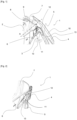
- a structural assembly 1 for a motor vehicle illustrated in the Figures 1 and 2 , includes a stretcher line, not shown, an upper support cup 2 for a wheel suspension system, shown in the figures, and, a wheel arch wall 3 for said wheel, illustrated in the Figure 1
- the assembly also comprises at least one sheet 4 forming a load path 5 extending from the stretcher line towards the cup 2.
- the wheel arch wall 3 is arranged between the cup 2 towards the rear of the assembly 1, the stretcher line in the lower part of the assembly 1, and the load path 5 in the upper part.
- a vehicle according to the invention thus comprises at least one assembly 1.
- the vehicle according to the invention also comprises, for example, advantageously a second load path consisting of cradle extensions, not illustrated.
- the cup 2 is generally a relatively thick sheet metal part, with a thickness of the order of 2 to 3 millimeters, due to its function of absorbing the forces of the suspension system, not shown.
- the cup 2 comprises a side wall 6 formed by at least one sheet having a substantially truncated cone shape with a square base whose corners are rounded.
- the cup 2 also comprises an upper wall 7 closing the volume delimited by the side wall 6.
- the upper wall 7 has a passage orifice 8 for a shock absorber head and means 9 for fixing the shock absorber head produced for example in the form of screw passage orifices provided in the cup 2.
- the wheel arch wall 3 is made of thinner sheet metal than the cup 2, with a thickness of the order of a millimeter, sometimes reinforced locally by one or more additional reinforcing elements.
- the force path 5 has a curve 10 oriented towards the outside of the vehicle. This force path 5 is designed to present force inputs, during an impact of a reduced frontal overlap test, towards the cup 2 causing the loss of the curve 10 of the force path 5.
- the assembly 1 further comprises a connecting member 11, illustrated in the Figure 1 , connecting the cup 2 and the force path 5.
- the connecting member 11 is shaped to deform in a predefined manner so as to transmit towards the cup 2, along a transverse axis A of the vehicle, illustrated in the Figure 1 , at least part of the longitudinal forces generated on the force path 5 during an impact of a reduced frontal overlap test.
- the connecting member 11 is designed to crush along the transverse axis A of the vehicle.
- the force path 5 loses its gable 10 and transmits forces along a longitudinal axis towards the cup 2.
- the connecting member 11 will deform in a predefined manner so as to crush along the transverse axis A of the vehicle to thus transmit forces towards the cup 2 along the transverse axis A.
- the assembly 1 according to the invention thanks to its connecting member 11, causes deformations of the cup 2 along the transverse axis A, which help the vehicle to deflect to avoid the barrier during a reduced frontal overlap test.
- the invention is not limited to the embodiment of the assembly described above, only by way of example, but other embodiments can be designed by those skilled in the art without departing from the framework and scope of the present invention.
Landscapes
- Engineering & Computer Science (AREA)
- Chemical & Material Sciences (AREA)
- Combustion & Propulsion (AREA)
- Transportation (AREA)
- Mechanical Engineering (AREA)
- Body Structure For Vehicles (AREA)
Description
- Le domaine technique concerne les ensembles de structure pour véhicules automobiles ainsi que les véhicules présentant au moins un tel ensemble.
- En matière de sécurité routière, les constructeurs d'automobiles doivent prendre en compte de multiples préoccupations et réglementations lors du développement de nouveaux véhicules afin, d'une part, d'assurer la sécurité des passagers du véhicule en cas de collision ou encore celle des autres usagers de la route les plus vulnérables tels que les piétons et, d'autre part, de maitriser les coûts de réparations des véhicules lorsqu'ils subissent des chocs urbains, dénommés chocs réparabilité subis à de faibles vitesses de l'ordre de 15 à 20 kilomètres par heure.
- Pour des chocs à des vitesses supérieures, de l'ordre de 50 km/h ou plus, les véhicules sont amenés à se déformer pour absorber une partie au moins de l'énergie libérée lors du choc, afin de protéger au mieux les passagers. Le comportement à la déformation d'un véhicule automobile, sous l'effet d'un choc, est particulièrement maitrisé par les constructeurs d'automobiles qui cherchent absolument à éviter que les déformations subies par le véhicule n'impactent l'habitacle et ses occupants.
- Les différents chocs que peut subir un véhicule sont simulés grâce à des procédures normalisées telles que, par exemple, celles décrites par l'organisme américain IIHS.
- Un test frontal particulièrement exigent proposé par l'IIHS est appelé « Small Overlap Front Test » ou test à chevauchement frontal réduit. Ce test est un type de test de choc frontal. Il consiste à propulser un véhicule à la vitesse de 40 mph, soit environ 64 km/h, sur une barrière rigide de 1,5 m de haut, qui frappe 25 % de l'avant du véhicule, du côté du conducteur. Le test simule la collision avec un véhicule venant en sens inverse, un arbre ou un poteau électrique.
- Un test à chevauchement frontal réduit affecte principalement les bords extérieurs du véhicule et les forces d'impact sont directement dirigées vers la roue avant, le système de suspension et la cloison pare-feu. Ainsi, il n'est pas rare que la roue soit repoussée vers l'arrière dans l'habitacle, en particulier dans l'espace pour les jambes, ce qui constitue une intrusion très préjudiciable susceptible d'entraîner de graves blessures aux jambes et aux pieds du conducteur. Idéalement, la structure du véhicule doit se déformer pour provoquer un déplacement transversal du véhicule afin que l'habitacle ne soit pas percuté par la barrière du test.
- La majorité des véhicules modernes présentent une conception de protection passive reposant sur deux voies d'effort : une première voie d'effort constituée du longeron ou encore ligne de brancard et une deuxième voie d'effort, encore appelée voie d'effort inférieure, constituée de prolonges de berceau. Certains véhicules comportent également une troisième voie d'effort qui est ménagée autour les passages de roues.
- Le document
EP 1 834 862 A1 décrit un ensemble de structure pour un véhicule automobile selon le préambule de la revendication 1. - L'examen des collisions entre deux véhicules montre que bien souvent les voies d'effort ont du mal à interagir entre elles et ainsi ne parviennent pas à transmettre les efforts à l'ensemble des éléments de la structure du véhicule. Par ailleurs la troisième voie d'effort est liée à la première voie d'effort via le passage de roue et ce dernier est également fixé sur le corps de la coupelle de suspension. Ainsi, la coupelle de suspension s'avère être un point faible. La coupelle de suspension porte ainsi souvent préjudice au comportement en déformation du véhicule lors d'un choc d'un test à chevauchement frontal réduit. Bien souvent le véhicule ne se déporte pas suffisamment pour éviter que l'habitacle ne percute la barrière. Ainsi, il existe un besoin d'une solution permettant d'améliorer le comportement du véhicule lors de la déformation consécutive à un test à chevauchement frontal réduit.
- La présente invention a pour objet de pallier les problèmes exposés précédemment. Dans ce contexte technique, un but de la présente invention est de fournir un ensemble de structure pour un véhicule automobile permettant d'améliorer le déport du véhicule durant le test à chevauchement frontal réduit.
- A cet effet, la présente invention se rapporte à un ensemble de structure pour un véhicule automobile comprenant une ligne de brancard et une coupelle de support supérieur pour un système de suspension d'une roue, l'ensemble comprenant une paroi de passage de roue pour ladite roue, l'ensemble comprenant en outre au moins une tôle conformée pour former une voie d'effort s'étendant depuis la ligne de brancard vers la coupelle, la paroi de passage de roue étant disposé entre la coupelle, la voie d'effort et la ligne de brancard, l'ensemble étant caractérisé en ce qu'il comporte un organe de liaison reliant la coupelle et la voie d'effort, l'organe de liaison étant conformé pour se déformer de manière prédéfinie de sorte à transmettre vers la coupelle, suivant un axe transversal du véhicule, au moins une partie des efforts longitudinaux engendrés sur la voie d'effort lors d'un test à chevauchement frontal réduit.
- L'invention concerne également un véhicule comportant au moins au moins un ensemble selon l'invention.
- Ainsi, l'ensemble selon l'invention, grâce à l'organe de liaison, permet de lier le comportement de la coupelle de support supérieur pour un système de suspension d'une roue à la voie d'effort. Compte tenu de sa conformation, l'organe de liaison permet en se déformant, lors d'un choc d'un test à chevauchement frontal réduit, d'engendrer des efforts et donc des déformations sur la coupelle suivant un axe transversal du véhicule. En se déformant suivant un axe transversal du véhicule, la coupelle améliore le comportement du véhicule selon l'invention lors du test à chevauchement frontal réduit et notamment son déport latéral.
- Dans le présent texte, un axe « transversal » se rapporte à un axe perpendiculaire à la direction longitudinale du véhicule équipé d'un ensemble. Selon un mode de réalisation de l'invention, l'organe de liaison est conçu pour s'écraser suivant un axe transversal du véhicule.
- Selon une possibilité, l'organe de liaison comporte une tôle emboutie présentant une section ayant une forme de V galbée.
- Selon un mode de réalisation, l'organe de liaison présente deux zones de soudure conçues pour fixer par soudure l'organe de liaison sur respectivement la coupelle et la voie d'effort.
- L'invention sera mieux comprise à la lecture de la description détaillée qui va suivre, donnée uniquement à titre d'exemple non limitatif et faite en se référant aux dessins annexés sur lesquels :
- [
Fig. 1 ] lafigure 1 , représente une vue en perspective d'un ensemble selon l'invention montrant l'organe de liaison ainsi que la coupelle et la voie d'effort ; - [
Fig. 2 ] lafigure 2 , représente une vue en perspective de l'organe de liaison de lafigure 1 après un choc d'un test à chevauchement frontal réduit. - Dans ces figures, les mêmes références sont utilisées pour désigner les mêmes éléments.
- Un ensemble 1 de structure pour un véhicule automobile, illustré sur les
figures 1 et 2 , comprend une ligne de brancard, non illustrée, une coupelle 2 de support supérieur pour un système de suspension d'une roue, illustrée sur les figures, et, une paroi de passage de roue 3 pour ladite roue, illustrée sur lafigure 1 . L'ensemble comporte également au moins une tôle 4 formant une voie d'effort 5 s'étendant depuis la ligne de brancard vers la coupelle 2. La paroi de passage de roue 3 est disposée entre la coupelle 2 vers l'arrière de l'ensemble 1, la ligne de brancard en partie basse de l'ensemble 1, et la voie d'effort 5 en partie haute. Un véhicule selon l'invention comporte ainsi au moins un ensemble 1. Le véhicule selon l'invention comporte également, par exemple, avantageusement une deuxième voie d'effort constituée de prolonges de berceau, non illustrée. - La coupelle 2 est généralement une pièce en tôle relativement épaisse, avec une épaisseur de l'ordre de 2 à 3 millimètres, du fait de sa fonction de reprise des efforts du système de suspension,non illustré. Ainsi et de façon classique la coupelle 2 comporte une paroi latérale 6 formée par au moins une tôle présentant une forme sensiblement tronconique à base carrée dont les coins sont arrondis. La coupelle 2 comporte également une paroi supérieure 7 fermant le volume délimité par la paroi latérale 6. La paroi supérieure 7 présente un orifice de passage 8 d'une tête d'amortisseur et des moyens de fixation 9 de la tête d'amortisseur réalisés par exemple sous la forme d'orifices de passage de vis prévus dans la coupelle 2.
- La paroi de passage de roue 3 est réalisée en tôle plus mince que la coupelle 2, avec une épaisseur de l'ordre du millimètre, parfois renforcé localement par un ou plusieurs éléments de renfort supplémentaires.
- La voie d'effort 5 présente un galbe 10 orienté vers l'extérieur du véhicule. Cette voie d'effort 5 est conçue pour présenter des entrées d'effort, lors d'un choc d'un test à chevauchement frontal réduit, vers la coupelle 2 provoquant la perte du galbe 10 de la voie d'effort 5.
- L'ensemble 1 comporte en outre un organe de liaison 11, illustré sur la
figure 1 , reliant la coupelle 2 et la voie d'effort 5. L'organe de liaison 11 est conformé pour se déformer de manière prédéfinie de sorte à transmettre vers la coupelle 2, suivant un axe transversal A du véhicule, illustré sur lafigure 1 , au moins une partie des efforts longitudinaux engendrés sur la voie d'effort 5 lors d'un choc d'un test à chevauchement frontal réduit. Avantageusement, l'organe de liaison 11 est conçu pour s'écraser suivant l'axe transversal A du véhicule. - Dans le mode de réalisation de l'invention, l'organe de liaison 11 comporte une tôle emboutie 12 présentant une section en forme de V galbée, suivant un plan horizontal du véhicule. L'organe de liaison 11 présente deux zones de soudure 13 conçues pour relier par soudure respectivement la coupelle 2, au niveau de la paroi latérale 6, et la voie d'effort 5.
- Ainsi, Lors d'un choc d'un test à chevauchement frontal réduit, la voie d'effort 5 perd son gable 10 et transmet des efforts suivant un axe longitudinal en direction de la coupelle 2. L'organe de liaison 11 va se déformer de manière prédéfinie de sorte à s'écraser suivant l'axe transversal A du véhicule pour ainsi transmettre vers la coupelle 2 des efforts suivant l'axe transversal A.
- Ainsi, l'ensemble 1 selon l'invention, grâce à son organe de liaison 11, provoque des déformations de la coupelle 2 suivant l'axe transversal A, qui aident au déport du véhicule pour éviter la barrière lors d'un test à chevauchement frontal réduit. L'invention ne se limite pas au mode de réalisation de l'ensemble décrit ci-avant, seulement à titre d'exemple, mais d'autres modes de réalisation peuvent être conçus par l'homme de métier sans sortir du cadre et de la portée de la présente invention.
Claims (5)
- Ensemble (1) de structure pour un véhicule automobile comprenant une ligne de brancard et une coupelle (2) de support supérieur pour un système de suspension d'une roue, l'ensemble comprenant une paroi de passage de roue (3) pour ladite roue, l'ensemble (1) comprenant en outre au moins une tôle (4) conformée pour former une voie d'effort (5) s'étendant depuis la ligne de brancard vers la coupelle (2), la paroi de passage de roue (3) étant disposé entre la coupelle (2), la voie d'effort (5) et la ligne de brancard, l'ensemble (1) comportant un organe de liaison (11) reliant la coupelle (2) et la voie d'effort (5), l'ensemble étant caractérisé en ce que l'organe de liaison (11) étant conformé pour se déformer de manière prédéfinie de sorte à transmettre vers la coupelle (2), suivant un axe transversal (A) du véhicule, au moins une partie des efforts longitudinaux engendrés sur la voie d'effort (5) lors d'un test à chevauchement frontal réduit.
- Ensemble (1) selon la revendication 1, caractérisé en ce que l'organe de liaison (11) est conçu pour s'écraser suivant un axe transversal (A) du véhicule.
- Ensemble (1) selon la revendication 1 ou 2, caractérisé en ce que l'organe de liaison (11) comporte une tôle emboutie (12) présentant une section ayant une forme de V galbée.
- Ensemble (1) selon l'une des revendications 1 à 3, caractérisé en ce que l'organe de liaison (11) présente deux zones de soudure (13) conçues pour fixer par soudure l'organe de liaison (11) sur respectivement la coupelle (2) et la voie d'effort (5).
- Véhicule comportant au moins un ensemble (1) selon l'une des revendications 1 à 4.
Applications Claiming Priority (2)
| Application Number | Priority Date | Filing Date | Title |
|---|---|---|---|
| FR2106674A FR3124476B1 (fr) | 2021-06-23 | 2021-06-23 | Ensemble de structure de face avant pour un véhicule automobile. |
| PCT/FR2022/050905 WO2022269149A1 (fr) | 2021-06-23 | 2022-05-12 | Ensemble de structure de face avant pour un véhicule automobile |
Publications (2)
| Publication Number | Publication Date |
|---|---|
| EP4359287A1 EP4359287A1 (fr) | 2024-05-01 |
| EP4359287B1 true EP4359287B1 (fr) | 2025-06-25 |
Family
ID=77180211
Family Applications (1)
| Application Number | Title | Priority Date | Filing Date |
|---|---|---|---|
| EP22732282.3A Active EP4359287B1 (fr) | 2021-06-23 | 2022-05-12 | Ensemble de structure de face avant pour un véhicule automobile |
Country Status (5)
| Country | Link |
|---|---|
| US (1) | US12116041B2 (fr) |
| EP (1) | EP4359287B1 (fr) |
| CN (1) | CN117597287A (fr) |
| FR (1) | FR3124476B1 (fr) |
| WO (1) | WO2022269149A1 (fr) |
Families Citing this family (1)
| Publication number | Priority date | Publication date | Assignee | Title |
|---|---|---|---|---|
| FR3152475B1 (fr) | 2023-08-30 | 2025-07-18 | Psa Automobiles Sa | Structure de véhicule automobile avec troisième voie renforcée |
Family Cites Families (4)
| Publication number | Priority date | Publication date | Assignee | Title |
|---|---|---|---|---|
| FR2106674A5 (en) | 1970-09-21 | 1972-05-05 | Bonnet Rene | Chicory prepn plant - with high speed washing and minimum handling |
| DE602007006247D1 (de) * | 2006-03-15 | 2010-06-17 | Mazda Motor | Vorderwagenaufbau eines Kraftfahrzeuges |
| FR2956643B1 (fr) * | 2010-02-25 | 2015-11-20 | Peugeot Citroen Automobiles Sa | Structure d'un vehicule comprenant un passage de roue a rigidite amelioree. |
| FR2967965B1 (fr) * | 2010-11-26 | 2012-11-16 | Peugeot Citroen Automobiles Sa | Ensemble de structure pour vehicule automobile comprenant une coupelle de support de systeme de suspension et une paroi de passage de roue |
-
2021
- 2021-06-23 FR FR2106674A patent/FR3124476B1/fr active Active
-
2022
- 2022-05-12 CN CN202280044726.8A patent/CN117597287A/zh active Pending
- 2022-05-12 US US18/562,907 patent/US12116041B2/en active Active
- 2022-05-12 WO PCT/FR2022/050905 patent/WO2022269149A1/fr not_active Ceased
- 2022-05-12 EP EP22732282.3A patent/EP4359287B1/fr active Active
Also Published As
| Publication number | Publication date |
|---|---|
| CN117597287A (zh) | 2024-02-23 |
| US20240262427A1 (en) | 2024-08-08 |
| FR3124476B1 (fr) | 2023-05-12 |
| WO2022269149A1 (fr) | 2022-12-29 |
| EP4359287A1 (fr) | 2024-05-01 |
| US12116041B2 (en) | 2024-10-15 |
| FR3124476A1 (fr) | 2022-12-30 |
Similar Documents
| Publication | Publication Date | Title |
|---|---|---|
| EP1942033B1 (fr) | Pièce d'appui pour système d'absorption de chocs destinée à être montée en bout d'un longeron d'un véhicule automobile | |
| WO2023062298A1 (fr) | Véhicule automobile avec brancards rapprochés et compatibles choc frontal à faible recouvrement | |
| EP3702222B1 (fr) | Dispositif de protection pour un véhicule automobile | |
| WO2001034451A1 (fr) | Vehicule, notamment de tourisme, a structure d'encaissement de choc anti-chevauchement | |
| EP4359287A1 (fr) | Ensemble de structure de face avant pour un véhicule automobile | |
| FR3140060A1 (fr) | Structure de véhicule avec renforts de traverse d’assise réduits. | |
| WO2023079223A1 (fr) | Sous-ensemble structurel de pare-chocs comportant un renfort de pare-chocs et deux équerres de fixation latérales | |
| WO2022175610A1 (fr) | Montage de traverse avant pour crash test « small overlap » | |
| FR3094328A1 (fr) | Vehicule avec renfort au niveau du passage de roue avant | |
| EP1854676A2 (fr) | Ensemble d'absorption d'energie et vehicle automobile comportant au moins un tel ensemble | |
| EP1660364B1 (fr) | Structure d'une partie avant de vehicule automobile | |
| EP1693283B1 (fr) | Structure avant de véhicule automobile | |
| FR2990920A1 (fr) | Dispositif de structure destine a etre monte sur un element de chassis de vehicule automobile | |
| FR3142414A1 (fr) | Structure de véhicule automobile avec appuis de façade renforcés | |
| FR3165437A1 (fr) | Dispositif de renforcement d’une caisse de véhicule. | |
| FR2871122A1 (fr) | Poutre de pare-chocs a moyens de montage d'un organe de remorquage et vehicule automobile correspondant | |
| FR2869377A1 (fr) | Boitier de deformation pour vehicule automobile | |
| FR3159582A1 (fr) | Dispositif déflecteur pour chocs avant à faible recouvrement. | |
| FR3158488A1 (fr) | Structure de caisse pour véhicule automobile | |
| EP4403420A1 (fr) | Face avant présentant une armature clipsée sur un absorbeur | |
| FR3167116A1 (fr) | dispositif de protection de soubassement de véhicule électrique. | |
| FR2952017A1 (fr) | Partie avant de caisse de vehicule automobile | |
| FR3162721A1 (fr) | Structure de véhicule tricycle. | |
| FR3127179A1 (fr) | Dispositif de renfort d’une poutre de pare-chocs présentant des surfaces inclinées adaptées aux différents chocs tests. | |
| FR3120337A1 (fr) | Platine d’interface de renfort de pare-chocs pour véhicule automobile |
Legal Events
| Date | Code | Title | Description |
|---|---|---|---|
| STAA | Information on the status of an ep patent application or granted ep patent |
Free format text: STATUS: UNKNOWN |
|
| STAA | Information on the status of an ep patent application or granted ep patent |
Free format text: STATUS: THE INTERNATIONAL PUBLICATION HAS BEEN MADE |
|
| PUAI | Public reference made under article 153(3) epc to a published international application that has entered the european phase |
Free format text: ORIGINAL CODE: 0009012 |
|
| STAA | Information on the status of an ep patent application or granted ep patent |
Free format text: STATUS: REQUEST FOR EXAMINATION WAS MADE |
|
| 17P | Request for examination filed |
Effective date: 20231219 |
|
| AK | Designated contracting states |
Kind code of ref document: A1 Designated state(s): AL AT BE BG CH CY CZ DE DK EE ES FI FR GB GR HR HU IE IS IT LI LT LU LV MC MK MT NL NO PL PT RO RS SE SI SK SM TR |
|
| DAV | Request for validation of the european patent (deleted) | ||
| DAX | Request for extension of the european patent (deleted) | ||
| GRAP | Despatch of communication of intention to grant a patent |
Free format text: ORIGINAL CODE: EPIDOSNIGR1 |
|
| STAA | Information on the status of an ep patent application or granted ep patent |
Free format text: STATUS: GRANT OF PATENT IS INTENDED |
|
| INTG | Intention to grant announced |
Effective date: 20250130 |
|
| GRAS | Grant fee paid |
Free format text: ORIGINAL CODE: EPIDOSNIGR3 |
|
| GRAA | (expected) grant |
Free format text: ORIGINAL CODE: 0009210 |
|
| STAA | Information on the status of an ep patent application or granted ep patent |
Free format text: STATUS: THE PATENT HAS BEEN GRANTED |
|
| AK | Designated contracting states |
Kind code of ref document: B1 Designated state(s): AL AT BE BG CH CY CZ DE DK EE ES FI FR GB GR HR HU IE IS IT LI LT LU LV MC MK MT NL NO PL PT RO RS SE SI SK SM TR |
|
| REG | Reference to a national code |
Ref country code: GB Ref legal event code: FG4D Free format text: NOT ENGLISH |
|
| REG | Reference to a national code |
Ref country code: CH Ref legal event code: EP |
|
| REG | Reference to a national code |
Ref country code: DE Ref legal event code: R084 Ref document number: 602022016495 Country of ref document: DE |
|
| REG | Reference to a national code |
Ref country code: CH Ref legal event code: EP |
|
| REG | Reference to a national code |
Ref country code: IE Ref legal event code: FG4D Free format text: LANGUAGE OF EP DOCUMENT: FRENCH |
|
| REG | Reference to a national code |
Ref country code: DE Ref legal event code: R096 Ref document number: 602022016495 Country of ref document: DE |
|
| PG25 | Lapsed in a contracting state [announced via postgrant information from national office to epo] |
Ref country code: FI Free format text: LAPSE BECAUSE OF FAILURE TO SUBMIT A TRANSLATION OF THE DESCRIPTION OR TO PAY THE FEE WITHIN THE PRESCRIBED TIME-LIMIT Effective date: 20250625 |
|
| REG | Reference to a national code |
Ref country code: LT Ref legal event code: MG9D |
|
| PG25 | Lapsed in a contracting state [announced via postgrant information from national office to epo] |
Ref country code: NO Free format text: LAPSE BECAUSE OF FAILURE TO SUBMIT A TRANSLATION OF THE DESCRIPTION OR TO PAY THE FEE WITHIN THE PRESCRIBED TIME-LIMIT Effective date: 20250925 Ref country code: GR Free format text: LAPSE BECAUSE OF FAILURE TO SUBMIT A TRANSLATION OF THE DESCRIPTION OR TO PAY THE FEE WITHIN THE PRESCRIBED TIME-LIMIT Effective date: 20250926 |
|
| PG25 | Lapsed in a contracting state [announced via postgrant information from national office to epo] |
Ref country code: BG Free format text: LAPSE BECAUSE OF FAILURE TO SUBMIT A TRANSLATION OF THE DESCRIPTION OR TO PAY THE FEE WITHIN THE PRESCRIBED TIME-LIMIT Effective date: 20250625 |
|
| PG25 | Lapsed in a contracting state [announced via postgrant information from national office to epo] |
Ref country code: HR Free format text: LAPSE BECAUSE OF FAILURE TO SUBMIT A TRANSLATION OF THE DESCRIPTION OR TO PAY THE FEE WITHIN THE PRESCRIBED TIME-LIMIT Effective date: 20250625 |
|
| PG25 | Lapsed in a contracting state [announced via postgrant information from national office to epo] |
Ref country code: RS Free format text: LAPSE BECAUSE OF FAILURE TO SUBMIT A TRANSLATION OF THE DESCRIPTION OR TO PAY THE FEE WITHIN THE PRESCRIBED TIME-LIMIT Effective date: 20250925 |
|
| PG25 | Lapsed in a contracting state [announced via postgrant information from national office to epo] |
Ref country code: LV Free format text: LAPSE BECAUSE OF FAILURE TO SUBMIT A TRANSLATION OF THE DESCRIPTION OR TO PAY THE FEE WITHIN THE PRESCRIBED TIME-LIMIT Effective date: 20250625 |
|
| REG | Reference to a national code |
Ref country code: NL Ref legal event code: MP Effective date: 20250625 |
|
| PG25 | Lapsed in a contracting state [announced via postgrant information from national office to epo] |
Ref country code: NL Free format text: LAPSE BECAUSE OF FAILURE TO SUBMIT A TRANSLATION OF THE DESCRIPTION OR TO PAY THE FEE WITHIN THE PRESCRIBED TIME-LIMIT Effective date: 20250625 |
|
| PG25 | Lapsed in a contracting state [announced via postgrant information from national office to epo] |
Ref country code: PT Free format text: LAPSE BECAUSE OF FAILURE TO SUBMIT A TRANSLATION OF THE DESCRIPTION OR TO PAY THE FEE WITHIN THE PRESCRIBED TIME-LIMIT Effective date: 20251027 |
|
| REG | Reference to a national code |
Ref country code: AT Ref legal event code: MK05 Ref document number: 1806205 Country of ref document: AT Kind code of ref document: T Effective date: 20250625 |
|
| PG25 | Lapsed in a contracting state [announced via postgrant information from national office to epo] |
Ref country code: IS Free format text: LAPSE BECAUSE OF FAILURE TO SUBMIT A TRANSLATION OF THE DESCRIPTION OR TO PAY THE FEE WITHIN THE PRESCRIBED TIME-LIMIT Effective date: 20251025 |
|
| PG25 | Lapsed in a contracting state [announced via postgrant information from national office to epo] |
Ref country code: AT Free format text: LAPSE BECAUSE OF FAILURE TO SUBMIT A TRANSLATION OF THE DESCRIPTION OR TO PAY THE FEE WITHIN THE PRESCRIBED TIME-LIMIT Effective date: 20250625 Ref country code: SM Free format text: LAPSE BECAUSE OF FAILURE TO SUBMIT A TRANSLATION OF THE DESCRIPTION OR TO PAY THE FEE WITHIN THE PRESCRIBED TIME-LIMIT Effective date: 20250625 |
|
| PG25 | Lapsed in a contracting state [announced via postgrant information from national office to epo] |
Ref country code: CZ Free format text: LAPSE BECAUSE OF FAILURE TO SUBMIT A TRANSLATION OF THE DESCRIPTION OR TO PAY THE FEE WITHIN THE PRESCRIBED TIME-LIMIT Effective date: 20250625 |
|
| PG25 | Lapsed in a contracting state [announced via postgrant information from national office to epo] |
Ref country code: PL Free format text: LAPSE BECAUSE OF FAILURE TO SUBMIT A TRANSLATION OF THE DESCRIPTION OR TO PAY THE FEE WITHIN THE PRESCRIBED TIME-LIMIT Effective date: 20250625 |
|
| PG25 | Lapsed in a contracting state [announced via postgrant information from national office to epo] |
Ref country code: EE Free format text: LAPSE BECAUSE OF FAILURE TO SUBMIT A TRANSLATION OF THE DESCRIPTION OR TO PAY THE FEE WITHIN THE PRESCRIBED TIME-LIMIT Effective date: 20250625 |
|
| PG25 | Lapsed in a contracting state [announced via postgrant information from national office to epo] |
Ref country code: SK Free format text: LAPSE BECAUSE OF FAILURE TO SUBMIT A TRANSLATION OF THE DESCRIPTION OR TO PAY THE FEE WITHIN THE PRESCRIBED TIME-LIMIT Effective date: 20250625 |
|
| PG25 | Lapsed in a contracting state [announced via postgrant information from national office to epo] |
Ref country code: ES Free format text: LAPSE BECAUSE OF FAILURE TO SUBMIT A TRANSLATION OF THE DESCRIPTION OR TO PAY THE FEE WITHIN THE PRESCRIBED TIME-LIMIT Effective date: 20250625 |
|
| REG | Reference to a national code |
Ref country code: DE Ref legal event code: R097 Ref document number: 602022016495 Country of ref document: DE |
|
| PG25 | Lapsed in a contracting state [announced via postgrant information from national office to epo] |
Ref country code: DK Free format text: LAPSE BECAUSE OF FAILURE TO SUBMIT A TRANSLATION OF THE DESCRIPTION OR TO PAY THE FEE WITHIN THE PRESCRIBED TIME-LIMIT Effective date: 20250625 |
|
| PLBE | No opposition filed within time limit |
Free format text: ORIGINAL CODE: 0009261 |
|
| STAA | Information on the status of an ep patent application or granted ep patent |
Free format text: STATUS: NO OPPOSITION FILED WITHIN TIME LIMIT |
|
| REG | Reference to a national code |
Ref country code: CH Ref legal event code: L10 Free format text: ST27 STATUS EVENT CODE: U-0-0-L10-L00 (AS PROVIDED BY THE NATIONAL OFFICE) Effective date: 20260507 |