EP4359207B1 - Thermoplastischer verbundschlauch zum transport von flüssigkeiten und flexibles rohr damit - Google Patents
Thermoplastischer verbundschlauch zum transport von flüssigkeiten und flexibles rohr damit Download PDFInfo
- Publication number
- EP4359207B1 EP4359207B1 EP22737627.4A EP22737627A EP4359207B1 EP 4359207 B1 EP4359207 B1 EP 4359207B1 EP 22737627 A EP22737627 A EP 22737627A EP 4359207 B1 EP4359207 B1 EP 4359207B1
- Authority
- EP
- European Patent Office
- Prior art keywords
- thermoplastic
- composite
- layer
- reinforcing
- sheath
- Prior art date
- Legal status (The legal status is an assumption and is not a legal conclusion. Google has not performed a legal analysis and makes no representation as to the accuracy of the status listed.)
- Active
Links
Images

Classifications
-
- B—PERFORMING OPERATIONS; TRANSPORTING
- B32—LAYERED PRODUCTS
- B32B—LAYERED PRODUCTS, i.e. PRODUCTS BUILT-UP OF STRATA OF FLAT OR NON-FLAT, e.g. CELLULAR OR HONEYCOMB, FORM
- B32B27/00—Layered products comprising a layer of synthetic resin
- B32B27/28—Layered products comprising a layer of synthetic resin comprising synthetic resins not wholly covered by any one of the sub-groups B32B27/30 - B32B27/42
- B32B27/288—Layered products comprising a layer of synthetic resin comprising synthetic resins not wholly covered by any one of the sub-groups B32B27/30 - B32B27/42 comprising polyketones
-
- F—MECHANICAL ENGINEERING; LIGHTING; HEATING; WEAPONS; BLASTING
- F16—ENGINEERING ELEMENTS AND UNITS; GENERAL MEASURES FOR PRODUCING AND MAINTAINING EFFECTIVE FUNCTIONING OF MACHINES OR INSTALLATIONS; THERMAL INSULATION IN GENERAL
- F16L—PIPES; JOINTS OR FITTINGS FOR PIPES; SUPPORTS FOR PIPES, CABLES OR PROTECTIVE TUBING; MEANS FOR THERMAL INSULATION IN GENERAL
- F16L11/00—Hoses, i.e. flexible pipes
- F16L11/04—Hoses, i.e. flexible pipes made of rubber or flexible plastics
- F16L11/08—Hoses, i.e. flexible pipes made of rubber or flexible plastics with reinforcements embedded in the wall
- F16L11/081—Hoses, i.e. flexible pipes made of rubber or flexible plastics with reinforcements embedded in the wall comprising one or more layers of a helically wound cord or wire
- F16L11/083—Hoses, i.e. flexible pipes made of rubber or flexible plastics with reinforcements embedded in the wall comprising one or more layers of a helically wound cord or wire three or more layers
-
- B—PERFORMING OPERATIONS; TRANSPORTING
- B32—LAYERED PRODUCTS
- B32B—LAYERED PRODUCTS, i.e. PRODUCTS BUILT-UP OF STRATA OF FLAT OR NON-FLAT, e.g. CELLULAR OR HONEYCOMB, FORM
- B32B1/00—Layered products having a non-planar shape
- B32B1/08—Tubular products
-
- B—PERFORMING OPERATIONS; TRANSPORTING
- B32—LAYERED PRODUCTS
- B32B—LAYERED PRODUCTS, i.e. PRODUCTS BUILT-UP OF STRATA OF FLAT OR NON-FLAT, e.g. CELLULAR OR HONEYCOMB, FORM
- B32B27/00—Layered products comprising a layer of synthetic resin
- B32B27/12—Layered products comprising a layer of synthetic resin next to a fibrous or filamentary layer
-
- B—PERFORMING OPERATIONS; TRANSPORTING
- B32—LAYERED PRODUCTS
- B32B—LAYERED PRODUCTS, i.e. PRODUCTS BUILT-UP OF STRATA OF FLAT OR NON-FLAT, e.g. CELLULAR OR HONEYCOMB, FORM
- B32B27/00—Layered products comprising a layer of synthetic resin
- B32B27/28—Layered products comprising a layer of synthetic resin comprising synthetic resins not wholly covered by any one of the sub-groups B32B27/30 - B32B27/42
- B32B27/285—Layered products comprising a layer of synthetic resin comprising synthetic resins not wholly covered by any one of the sub-groups B32B27/30 - B32B27/42 comprising polyethers
-
- B—PERFORMING OPERATIONS; TRANSPORTING
- B32—LAYERED PRODUCTS
- B32B—LAYERED PRODUCTS, i.e. PRODUCTS BUILT-UP OF STRATA OF FLAT OR NON-FLAT, e.g. CELLULAR OR HONEYCOMB, FORM
- B32B5/00—Layered products characterised by the non- homogeneity or physical structure, i.e. comprising a fibrous, filamentary, particulate or foam layer; Layered products characterised by having a layer differing constitutionally or physically in different parts
- B32B5/02—Layered products characterised by the non- homogeneity or physical structure, i.e. comprising a fibrous, filamentary, particulate or foam layer; Layered products characterised by having a layer differing constitutionally or physically in different parts characterised by structural features of a fibrous or filamentary layer
-
- B—PERFORMING OPERATIONS; TRANSPORTING
- B32—LAYERED PRODUCTS
- B32B—LAYERED PRODUCTS, i.e. PRODUCTS BUILT-UP OF STRATA OF FLAT OR NON-FLAT, e.g. CELLULAR OR HONEYCOMB, FORM
- B32B2260/00—Layered product comprising an impregnated, embedded, or bonded layer wherein the layer comprises an impregnation, embedding, or binder material
- B32B2260/02—Composition of the impregnated, bonded or embedded layer
- B32B2260/021—Fibrous or filamentary layer
- B32B2260/023—Two or more layers
-
- B—PERFORMING OPERATIONS; TRANSPORTING
- B32—LAYERED PRODUCTS
- B32B—LAYERED PRODUCTS, i.e. PRODUCTS BUILT-UP OF STRATA OF FLAT OR NON-FLAT, e.g. CELLULAR OR HONEYCOMB, FORM
- B32B2260/00—Layered product comprising an impregnated, embedded, or bonded layer wherein the layer comprises an impregnation, embedding, or binder material
- B32B2260/04—Impregnation, embedding, or binder material
- B32B2260/046—Synthetic resin
-
- B—PERFORMING OPERATIONS; TRANSPORTING
- B32—LAYERED PRODUCTS
- B32B—LAYERED PRODUCTS, i.e. PRODUCTS BUILT-UP OF STRATA OF FLAT OR NON-FLAT, e.g. CELLULAR OR HONEYCOMB, FORM
- B32B2262/00—Composition or structural features of fibres which form a fibrous or filamentary layer or are present as additives
- B32B2262/10—Inorganic fibres
- B32B2262/106—Carbon fibres, e.g. graphite fibres
-
- B—PERFORMING OPERATIONS; TRANSPORTING
- B32—LAYERED PRODUCTS
- B32B—LAYERED PRODUCTS, i.e. PRODUCTS BUILT-UP OF STRATA OF FLAT OR NON-FLAT, e.g. CELLULAR OR HONEYCOMB, FORM
- B32B2307/00—Properties of the layers or laminate
- B32B2307/50—Properties of the layers or laminate having particular mechanical properties
- B32B2307/546—Flexural strength; Flexion stiffness
-
- B—PERFORMING OPERATIONS; TRANSPORTING
- B32—LAYERED PRODUCTS
- B32B—LAYERED PRODUCTS, i.e. PRODUCTS BUILT-UP OF STRATA OF FLAT OR NON-FLAT, e.g. CELLULAR OR HONEYCOMB, FORM
- B32B2597/00—Tubular articles, e.g. hoses, pipes
Definitions
- the present invention relates to a thermoplastic composite pipe useful for transporting fluids, and a flexible conduit comprising such a thermoplastic composite pipe and useful for transporting fluids, in particular hydrocarbons.
- Thermoplastic composite pipes are known as “Thermoplastic Composite Pipe” (TCP) and are described in particular in the normative document DNVGL-ST-F119, “ Standard Practice - Thermoplastic composites pipes”, published in September 2019 by DNV GL (Det Norske Veritas GL) .
- the tubular reinforcement structure is connected to the tubular inner sheath, in order to avoid the crushing ("collapse" in English) of the tubular inner sheath during rapid decompression of the pipe transporting the fluid, in particular if it contains gases, which is the case with hydrocarbons.
- bonded we mean that the tubular reinforcement structure and the tubular inner sheath are not free to move relative to each other. They can be bonded by gluing (using glue or adhesive) or by welding.
- the external protective sheath is optional but when present, it is advantageously linked to the tubular reinforcement structure, the assembly thus forming a TCP pipe with a completely linked structure.
- thermoplastic composite pipes are marketed in particular by the companies Magma Global Ltd (TCP registered trademark m-pipe ® ) and Strohm, or described in the literature.
- the application WO 2006/059220 describes a pipe comprising an inner sheath made of thermoplastic material, in particular polyamide, polyvinylidene fluoride (PVDF), poly(phenylene sulfide) (PPS), polyetheretherketone (PEEK), around which is wound a strip of reinforced thermoplastic material, for example with glass or carbon fibers, this strip being wound around the inner sheath and bonded to it.
- PVDF polyvinylidene fluoride
- PPS poly(phenylene sulfide)
- PEEK polyetheretherketone
- a reinforcing layer based on glass, carbon or aramid fibers impregnated within a thermoplastic resin may be added.
- TCPs One of the obstacles to the use of TCPs is their poor bending performance, which leads to a high minimum bend radius (MBR).
- MRR minimum bend radius
- the bonded structure of TCPs makes them more rigid than pipes made from layers that are not bonded to each other, i.e., in which the layers can move relative to each other.
- This stiffness of the TCP is particularly observed when the thermoplastic matrix of the intermediate reinforcing tubular structure is based on polyetheretherketone (also called PEEK or poly(oxy1,4-phenyleneoxy-1,4-phenylenecarbonyl-1,4-phenylene).
- PEEK poly(oxy1,4-phenyleneoxy-1,4-phenylenecarbonyl-1,4-phenylene
- TCPs can be used as such, but they can also be integrated into more complex tubular structures.
- TCPs can be used within so-called “hybrid” flexible pipes (HFP) which have a structure intermediate between that of TCP thermoplastic composite pipes and that of unbonded flexible pipes, described below.
- HFP hybrid flexible pipes
- Flexible pipes are described in particular in the normative document API 17J, “Specification for Unbonded Flexible Pipe,” 4th Edition, May 2014 published by the American Petroleum Institute They are used particularly in deep water in the oil and gas industry. Typically, they are used for the transport of hydrocarbon fluids, or for the reinjection of carbon dioxide into a subsea reservoir.
- Flexible oil pipelines generally extend across a body of water between a surface assembly and a bottom assembly. These pipelines can also extend between two surface assemblies.
- the bottom assembly is intended to collect the fluid exploited at the bottom of the body of water.
- the surface assembly is generally floating. It is intended to collect, potentially treat, and distribute the fluid.
- the surface assembly can be a semi-submersible platform, an FPSO, or another floating assembly.
- the flexible pipe has a length greater than 800 m, or even greater than 1000 m or 2000 m for applications in ultra-deep water.
- the flexible pipe is sized to withstand very high hydrostatic pressure, for example 200 bar for a pipe submerged at a depth of 2000 m.
- the flexible pipe is generally sized to withstand axial tension greater than the total weight of the flexible pipe suspended from a surface assembly and extending underwater from the surface to the seabed. This is particularly the case when the flexible pipe is used as a riser intended to provide a vertical connection between the seabed and the surface assembly in service.
- the ability of the flexible pipe to support its own weight when suspended in the water makes it easier to install at sea from a laying vessel.
- lightweight flexible pipes comprising a tubular reinforcement structure made of composite material comprising a thermoplastic matrix and reinforcing fibers embedded in the matrix have been developed, namely so-called “hybrid” flexible pipes.
- the tubular reinforcement structure generally takes up most of the radial forces applied to the hybrid flexible pipe.
- the tubular reinforcement structure, linked to the internal tubular polymeric sealing sheath, also has a barrier function to gases, such as acid gases of the H 2 S and CO 2 type contained in the hydrocarbons transported inside the internal tubular polymeric sheath. It thus makes it possible to protect the metallic reinforcement elements of the flexible pipe against corrosion phenomena or the composite material of the reinforcement layer from degradation induced by these gases.
- the reinforcement layer(s) made of metal wires or composite material are similar to those of unbonded flexible pipes, i.e. they are made of helically wound wires. These are generally tensile armor plies.
- these hybrid flexible pipes may comprise an internal carcass located inside the tubular internal polymeric sheath, said internal carcass having the function of increasing the resistance to crushing ("collapse" in English) of the pipe.
- the internal carcass is formed for example from a profiled metal strip, wound in a spiral. The turns of the strip are advantageously stapled to each other, which makes it possible to absorb the crushing forces.
- One of the aims of the invention is to provide a thermoplastic composite pipe useful for the transport of fluids whose bending performance is improved, and in particular whose minimum bending radius is reduced.
- Another object of the invention is to provide a hybrid flexible pipe whose bending performance is improved, and in particular whose minimum radius of curvature is reduced.
- the PEEK used within the thermoplastic matrix of each reinforcing layer has a viscosity as measured at 400°C according to the ISO 11443 standard of 2021 greater than 200 Pa.s, in particular greater than 250 Pa.s, preferably greater than 300 Pa.s.
- the viscosity of PEEK increases in particular with its mass average molecular weight (Mw).
- the inventors have discovered that a composite reinforcement structure whose reinforcement layers are based on a PEEK having a molecular weight distribution and a Charpy impact strength as defined above makes it possible to obtain a thermoplastic composite pipe whose flexural performance is very significantly improved. This improvement is exacerbated when the PEEK has the viscosity defined above.
- thermoplastic composite pipe according to the invention advantageously has a smaller minimum bend radius (MBR) than a thermoplastic composite pipe whose reinforcing layers of the composite reinforcement structure comprise a PEEK not having such a molecular weight distribution, and/or such Charpy impact strength. This reduction in MBR is exacerbated when the PEEK has the viscosity defined above.
- the PEEK used within the thermoplastic matrix of each reinforcing layer may be linear or branched, and is preferably branched.
- the end groups of the PEEK used within the thermoplastic matrix of each reinforcing layer are typically selected from the group consisting of F, H, diphenyl ether, phenyl, methylphenyl (including o-, m- or p-tolyl), dimethylphenyl (including o-, m- or p-xylyl) and methoxyphenyl (including o-, m- or p-methoxyphenyl).
- F F
- H diphenyl ether
- phenyl methylphenyl (including o-, m- or p-tolyl)
- dimethylphenyl including o-, m- or p-xylyl
- methoxyphenyl including o-, m- or p-methoxyphenyl
- the crystallinity rate of the PEEK used within the thermoplastic matrix of each composite material strip of each reinforcing layer is in particular 10 to 50%, preferably 20 to 40%, particularly preferably 30 to 40%.
- the crystallinity level of PEEK used within the thermoplastic matrix and measured after the manufacture of the composite reinforcement layer is often different from the crystallinity level of the initial composite material strip (part of the PEEK being melted during the manufacture of the reinforcement layer, another part being unmelted but thermally affected).
- the crystallinity level of PEEK used within the thermoplastic matrix and measured after the manufacture of the reinforcement layer of the tubular reinforcement structure of the thermoplastic composite pipe, as measured by differential scanning calorimetry (DSC), is generally 20 to 40%, preferably 25 to 40%. Too low a crystallinity level can be detrimental to permeability and/or resistance to chemical aging.
- the PEEK used within the thermoplastic matrix of each reinforcement layer can be obtained by nucleophilic substitution polymerization, typically by polycondensation of 4,4'-difluorobenzophenone (BDF) with hydroquinone (HQ) or a salt thereof.
- BDF 4,4'-difluorobenzophenone
- HQ hydroquinone
- the polymerization is generally carried out in a high-boiling solvent such as diphenylsulfone (DPS).
- DPS diphenylsulfone
- Nucleophilic substitution polymerization generally produces linear PEEK.
- the terminal groups of PEEK are generally fluorines.
- the PEEK used within the thermoplastic matrix of each reinforcing layer may be obtained by electrophilic addition polymerization, typically by polymerization of phenoxyphenoxybenzoic acid (PPBA) in a mixture of methanesulfonic acid (MSA) and anhydrous methanesulfonic acid (MSAN).
- PPBA phenoxyphenoxybenzoic acid
- MSA methanesulfonic acid
- MSAN anhydrous methanesulfonic acid
- This mixture acts as both a solvent and a catalyst for the polymerization reaction.
- This may in particular be the process described in the application US 2002/0040124 Or CN 1162602A .
- the electrophilic addition polymerization process makes it possible to obtain a PEEK comprising branches, and this in a controlled manner, which can lead to an improvement in the mechanical properties, in particular the impact resistance and/or the fracture toughness.
- the terminal groups of the PEEK obtained by this process are generally chosen from diphenyl, phenyl, methylphenyl (in particular o-, m- or p-tolyl), dimethylphenyl (in particular o-, m- or p-xylyl) or methoxyphenyl (in particular o-, m- or p-methoxyphenyl) ether groups.
- Each reinforcement layer has a thermoplastic matrix reinforced with carbon fibers.
- Carbon fibers may be sized or unsized, and are preferably unsized.
- Their tow sizes are generally less than or equal to 50K, in particular less than or equal to 24K, preferably less than or equal to 12K. 50K corresponds to 50,000 filaments constituting the wick.
- the diameter of carbon fibers is generally less than 10 ⁇ m, especially less than 8 ⁇ m, for example between 4 ⁇ m and 8 ⁇ m.
- the carbon fibers have a sizing rate as determined according to the ISO 10548 standard of 2002 rectified in 2008 of less than 0.4%, in particular less than 0.2%, and preferably zero.
- these are, for example, carbon fibers of grade AS4, AS4a, AS7, marketed by Hexcel.
- the reinforcing layers based on a PEEK reinforced by such carbon fibers have in fact improved mechanical properties, in particular the interlaminar, transverse and plane shear strengths, characterized respectively according to the standards ASTM D2344 of 2016, ASTM D5450 of 2016 and ASTM D3518M of 2018, compared to carbon fibers whose sizing rate is higher.
- Carbon fibers generally have a maximum tensile strength greater than 3 GPa, preferably greater than 4 GPa, as measured at 23°C according to ASTM D885M - 10A(2014)e1.
- the terms "ultimate tensile strength” and “tensile strength” have the same meaning and designate the ultimate tensile strength measured during a tensile test.
- carbon fibers advantageously have a tensile modulus greater than 200 GPa, in particular greater than 220 GPa, as measured at 23°C according to ASTM Standard D885M - 10A(2014)e1.
- tensile modulus In the present application, the terms "tensile modulus”, “Young's modulus” and “tensile modulus of elasticity” have the same meaning and designate the modulus of elasticity measured during a tensile test.
- the volume fiber content of the carbon fibers within each reinforcing layer is from 30 to 70%, preferably from 40 to 60%, particularly preferably from 45 to 55% relative to the volume of the composite reinforcing layer.
- This volume content can be determined according to standard NF EN 2564 of 2018.
- a volume fiber content of the carbon fibers in the ranges of 30-70%, preferably 40-60%, particularly preferably 45-55% advantageously allows a good compromise between these resistances.
- the carbon fibers are preferably arranged, for each reinforcement layer, unidirectionally in the polymer matrix. They are then parallel to each other.
- the composite reinforcement structure bonded to the tubular inner sheath gives the thermoplastic composite pipe its radial strength.
- the composite reinforcement structure prevents the tubular inner sheath from being crushed during rapid decompression of the pipe carrying the fluid.
- thermoplastic composite pipe may be free of an additional outer layer.
- the outermost layer of the thermoplastic composite pipe is then the reinforcing composite structure.
- the thermoplastic composite pipe may include a sealing layer of a thermoplastic material around the reinforcing composite structure. Typically, this sealing layer is then the outermost layer of the reinforcing composite structure.
- the presence of the sealing layer which then covers the composite reinforcement structure, limits, preferably completely prevents, the entry of the external environment, in particular water, into the interior of the thermoplastic composite pipe. In particular, it makes it possible to protect the composite reinforcement structure against the harmful effects of the external environment, in particular by avoiding the formation of discontinuities.
- the outermost layer of the thermoplastic composite pipe is generally either the reinforcing composite structure or the sealing layer when the thermoplastic composite pipe contains such a layer.
- the flexible pipe according to the invention is therefore a “hybrid” flexible pipe.
- the flexible pipe according to the invention comprises the thermoplastic composite pipe according to the invention, it also has improved flexural performance compared to a flexible pipe whose PEEK does not have the mass distribution molecular weight and/or Charpy strength as defined above.
- the flexible pipe according to the invention advantageously has a smaller minimum radius of curvature than a flexible pipe whose reinforcing layers comprise a PEEK not meeting the definition above.
- the formation of the sealing layer may be achieved by wrapping around the reinforcing composite structure at least two strips of a thermoplastic material, and welding the at least two strips together.
- the sealing layer is formed by extruding a thermoplastic material onto the reinforcing composite structure.
- the invention relates to the use of the thermoplastic composite pipe defined above or the flexible pipe defined above for transporting fluids, in particular hydrocarbons.
- the invention also relates to a method for transporting fluids, in particular hydrocarbons, comprising transporting the fluid within the thermoplastic composite pipe defined above or the flexible pipe defined above.
- the pressure within the flexible pipe is generally greater than 100 bars, and can even reach 1000 bars, and the temperature is generally greater than 90°C, in particular 110°C, sometimes greater than 130°C, or even 170°C.
- the damage threshold can be determined by performing various bending tests at different strain levels and verifying the presence of cracks in the reinforcement layer by destructive analysis using optical microscopy or electron microscopy. Three types of results can be obtained. The first type of result corresponds to the absence of cracks. The second type of result corresponds to the observation of one or more non-through cracks. A crack is considered non-through when it does not extend from the inner skin of the reinforcement layer to the outer skin of the reinforcement layer. A third type of result corresponds to the observation of one or more through cracks. A crack is considered through when it extends from the inner skin of the reinforcement layer to the outer skin of the reinforcement layer.
- the damage threshold is determined by the strain level to be applied to allow the observation of one or more non-through cracks.
- the through cracking threshold is determined by the level of deformation to be applied to allow the observation of one or more through cracks.
- the bending deformation rate corresponding to the damage threshold of the thermoplastic composite pipe is greater than 2.0%, in particular greater than 2.5%, even more advantageously greater than 3.0%.
- the bending deformation rate corresponding to the through cracking threshold is greater than 3.0%, in particular greater than 4.0%, even more advantageously greater than 5.0%.
- the bending deformation rate at the damage threshold of the flexible pipe is greater than 2.0%, in particular greater than 2.5%... even more advantageously greater than 3.0%.
- the bending deformation rate corresponding to the through cracking threshold is greater than 3.0%, in particular greater than 4.0%, even more advantageously greater than 5.0%.
- outer or “external” and “inner” or “internal” are understood respectively as further radially from the axis of the thermoplastic composite pipe (or flexible conduit) and as closer radially to the axis of the thermoplastic composite pipe (or flexible conduit).
- thermoplastic composite pipe comprises a sealing layer 22. It would not be outside the scope of the invention if this layer were absent.
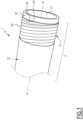
- thermoplastic composite pipe 1 according to the invention is schematically illustrated by the Figure 1 .
- the thermoplastic composite pipe 1 comprises a central section 2 illustrated in part on the Figure 1 . It comprises, at each of the axial ends of the central section 2, an end piece (not shown).
- the thermoplastic composite pipe 1 delimits an internal passage 13 for the circulation of a fluid, advantageously a petroleum fluid, in particular hydrocarbons.
- the internal passage 13 extends along an axis A-A', between the upstream end and the downstream end of the thermoplastic composite pipe 1. It opens out through the end pieces (not shown).
- the thermoplastic composite pipe 1 comprises at least one tubular internal polymeric sheath 20 advantageously constituting an internal sealing sheath, a tubular composite reinforcement structure 21, covering the tubular sheath 20 and being bonded to the latter, and a sealing layer 22, which covers the composite reinforcement structure 21.
- the tubular sheath 20 is intended to confine in a sealed manner the fluid transported in the passage 13.
- the tubular sheath 20 also has the function of protecting the composite reinforcement structure 21 against abrasion linked to the presence of abrasive particles, for example sand, within the fluid transported in the passage 13.
- the tubular sheath 20 generally comprises a polymer selected from PEK (polyetherketone), PEEK (polyetheretherketone), PEEKK (polyetheretherketoneketone), PEKK (polyetherketoneketone), PEKEKK (polyetherketoneetherketoneketone), and a mixture thereof, preferably a PEEK (polyetheretherketone)
- the tubular sheath 20 comprises another polymer, preferably thermoplastic.
- the polymer forming the tubular sheath 20 is chosen from a polyolefin such as polyethylene or polypropylene, a polyamide such as PA11 or PA12, or a fluoropolymer such as polyvinylidene fluoride (PVDF) or copolymers of polyvinylidene fluoride and polyhexafluoropropylene (PVDF-HFP), PAI (polyamide-imide), PEI (polyether-imide), PSU (polysulfone), PPSU (polyphenylsulfone), PES (polyethersulfone), PAS (polyarylsulfone), PPE (polyphenylene ether), PPS (polyphenylene sulfide), LCP (liquid crystal polymers), PPA (polyphthalamide), copolymers thereof, and/or mixtures thereof or a mixture of one or more of
- the tubular sheath 20 may for example comprise a mixture of polyaryletherketone and a polysiloxane, such as those described in the application WO 2019/150060 .
- the polymer of the tubular sheath 20 is advantageously of the same nature as that of the polymer matrix 40 defined below.
- the polymer of the tubular sheath 20 and the polymer of the polymer matrix 40 are capable of melting and forming an intimate mixture, without phase separation, after cooling.
- the polymer of the tubular sheath 20 is a polyaryletherketone (PAEK) such as polyetheretherketone (PEEK) or polyetherketoneketone (PEKK) or a mixture thereof.
- PAEK polyaryletherketone
- PEEK polyetheretherketone
- PEKK polyetherketoneketone
- the polymer of the tubular sheath 20 may be PEEK as defined above and used within the polymer matrix 40 defined below.
- the tubular sheath 20 comprises at least 50% by mass of the polymer defined above (or of the mixture thereof when it is a mixture), more preferably at least 75% by mass, even more preferably at least 80% by mass, typically at least 90% by mass, relative to the total mass of the tubular sheath 20.
- the tubular sheath 20 is made of one of the polymers defined above or one of the mixtures defined above and fillers and/or additives.
- the thickness of the tubular sheath 20 is for example between 1 mm and 20 mm.
- the tubular sheath 20 is formed from a tube of polymer material, a strip of assembled polymer material, or an impregnated polymer mat.
- tubular sheath 20 is formed from a tube, it is advantageously obtained by extrusion of a thermoplastic tube chosen in particular from the polymers mentioned above.
- the tubular sheath 20 is formed from a strip of assembled polymer material, it is advantageously produced by extrusion and winding of thermoplastic strips of a polymer as described above.
- the turns of a first layer are contiguous (edge to edge without overlap) and the turns of an upper layer are arranged so as to have an overlap of two lower adjacent strips ensuring the sealing of the tubular sheath 20.
- the composite reinforcement structure 21 covers the tubular sheath 20. It is assembled on the tubular sheath 20 to form an assembly linked with the tubular sheath 20.
- the composite reinforcement structure 21 comprises a winding of at least two laminated reinforcement layers, and optionally, an anti-delamination layer interposed between at least two reinforcement layers.
- Each laminated reinforcement layer comprises an overlay of composite reinforcement layers.
- each composite reinforcement layer comprises a polymer matrix 40 and carbon fibers 42 embedded in the polymer matrix 40.
- the polymeric matrix 40 comprises PEEK as defined above.
- the polymeric matrix 40 comprises at least 50% by mass of the PEEK defined above (or the mixture thereof when it is a mixture), more preferably at least 75% by mass, even more preferably at least 80% by mass, typically at least 90% by mass, preferably at least 95% by mass, relative to the total mass of the polymeric matrix 40.
- the polymer matrix 40 is made of a PEEK defined above or a mixture of PEEK defined above and fillers and/or additives. Carbon black is an example of a filler.
- the carbon fibers 42 are preferably as defined above.
- the carbon fibers 42 are preferably arranged, for each of the composite reinforcement layers, unidirectionally in the polymer matrix 40. They are then parallel to each other. Alternatively, the carbon fibers 42 are crossed in two orthogonal directions, or are arranged randomly in the matrix (not shown).
- the length of carbon fibers 42 in each composite layer is generally greater than 100 m, and is notably between 100 m and 4500 m.
- each composite reinforcing layer is formed from a winding of at least one composite strip 44 having several layers of carbon fibers 42 embedded in a polymer matrix 40, each strip having a length greater than at least 10 times its width and at least 10 times its thickness.
- each composite strip 44 is greater than 100 m and is between 100 m and 4500 m.
- the width of each composite strip 44 is between 6 mm and 50 mm.
- the thickness of each composite strip 44 is between 0.1 mm and 1 mm.
- each composite strip 44 has, at 23°C, a tensile modulus greater than 10 GPa, in particular between 30 GPa and 170 GPa, as measured by Standard NF EN 2561, January 1996, an elongation at break greater than 1%, in particular between 1% and 5%, as measured by Standard NF EN 2561, January 1996, and/or a maximum tensile strength greater than 100 MPa, and in particular between 350 MPa and 3500 MPa as measured by Standard NF EN 2561, January 1996.
- each composite strip 44 When producing each reinforcing layer, the or each composite strip 44 is wound in a helix around the axis AA' of the tubular sheath 20, and is heated to cause the partial melting of the polymer matrix 40, and the bonding with the successive turns of the composite strip 44 and the tubular sheath 20, and possibly with the adjacent external layer which may be another reinforcing layer, an anti-delamination layer, or the sealing layer 22.
- the absolute value of the winding helix angle ⁇ of each composite strip 44 relative to the axis A-A' of the thermoplastic composite pipe 1 is generally between 20° and 85°. This value depends on the intended application. When the thermoplastic composite pipe is used alone (i.e. not within a hybrid flexible pipe 10) and is intended to be put under internal pressure and/or under external pressure (flowline or jumper application), this value is typically between 45 and 65°, preferably between 50° and 60°. When the thermoplastic composite pipe is used alone (i.e. not within a hybrid flexible pipe 10) and is intended to be put under internal, external pressure and under tension, this value is typically between 20 and 85°.
- thermoplastic composite pipe When the thermoplastic composite pipe is intended to be used within a hybrid pipe, typically for flowline or riser applications, this value is typically between 50° and 85°, preferably between 55° and 70°. This ensures elongation of the composite under the effect of the internal pressure.
- thermoplastic composite pipe When used as the inner layer of a hybrid flexible conduit 10 (as shown in Figure 2 and described below), such a helix angle also allows adequate cooperation with the armor plies 24, 25.
- each laminated composite layer is generally between 1 mm and 30 mm.
- the number of composite layers within the reinforcing composite structure is typically from 2 to 300, in particular from 10 to 200, preferably from 20 to 100. Generally, this number is always even to ensure the balance of the reinforcing composite structure.
- the sealing layer 22 is intended to confine the composite reinforcement structure 21 in a sealed manner.
- the sealing layer has the function of limiting, preferably preventing, contact between the external environment, in particular water, and the composite reinforcement structure 21.
- the sealing layer 22 may be bonded or unbonded to the reinforcing composite structure 21.
- the permeability of the sealing layer 22 depends on the material chosen for its production as well as the temperature to which the sealing layer 22 is subsequently exposed.
- the water permeability of the polymer materials suitable for producing the sealing layer 22 is between 1 ⁇ 10 7 cm 3 (STP).cm -1 .s -1 .bar -1 and 2 ⁇ 10 -5 cm 3 (STP).cm -1 .s -1 .bar -1 .
- the water permeability of the layer is 5 ⁇ 10 -8 cm 3 (STP).cm -2 .s -1 .bar -1 to 2 ⁇ 10 -4 cm 3 (STP).cm -1 .s -1 .bar -1 .
- permeability of the sealing layer 22 is meant the capacity of said sealing layer 22 as a whole to allow water to pass through it.
- the permeability of the sealing layer may be different from the permeability of the material constituting the layer, in particular due to the presence of possible discontinuities or faults in the sealing layer which would facilitate the passage of water or because the sealing layer is made from a discontinuous structure such as a wound strip.
- the permeability of the sealing layer is understood here as that of the layer as a whole including the material and any interstices or interfaces between the discontinuous regions forming the layer.
- the permeability measurement refers to the permeability of the sealing layer as a whole, as it is present in the thermoplastic composite pipe 1 of the invention.
- the sealing layer 22 is formed from a thermoplastic material.
- the polymer forming the sealing layer 22 is selected from a polyolefin, optionally crosslinked, such as polyethylene or polypropylene; a thermoplastic elastomer (TPE) such as thermoplastic polyurethane (TPE-U or TPU) or styrenic copolymers (TPE-S or TPS) or vulcanized polypropylene and ethylene-propylene-diene copolymers (PP-EPDM) (TPE-V or TPV); a polyamide such as PA11 or PA12; or a fluoropolymer such as polyvinylidene fluoride (PVDF) or polyvinylidene fluoride and polyhexafluoropropylene copolymers (PVDF-HFP).
- TPE thermoplastic elastomer
- TPE-U or TPU thermoplastic polyurethane
- TPE-S or TPS styrenic copolymers
- the sealing layer 22 comprises a polymer selected from PEK (polyetherketone), PEEK (polyetheretherketone), PEEKK (polyetheretherketoneketone), PEKK (polyetherketoneketone), PEKEKK (polyetherketoneetherketoneketone), PAI (polyamide-imide), PEI (polyether-imide), PSU (polysulfone), PPSU (polyphenylsulfone), PES (polyethersulfone), PAS (polyarylsulfone), PPE (polyphenylene ether), PPS (polyphenylene sulfide), LCP (liquid crystal polymers), PPA (polyphthalamide) and/or mixtures thereof or a mixture of one or more of these with a polysiloxane, PTFE (polytetrafluoroethylene) or PFPE (perfluoropolyether).
- PEK polyetherketone
- PEEK polyetheretherketoneketone
- the sealing layer 22 may for example comprise a mixture of polyaryletherketone and a polysiloxane, such as those described in the application WO2019/150060 .
- the sealing layer 22 is made up of one of the polymers defined above or one of the mixtures thereof and fillers and/or additives.
- the polymer of the sealing layer 22 is advantageously of the same nature as that of the polymer matrix 40, more advantageously of the same nature as that of the polymer matrix 40 and that of the sheath 20.
- By “of the same nature" is meant in the sense of the present invention that the polymer of the sealing layer 22 and the polymer of the polymer matrix 40, and possibly the polymer of the tubular sheath 20, are capable of melting and forming an intimate mixture, without phase separation, after cooling.
- the polymer of the sealing layer 22 may be PEEK as defined above and used within the polymer matrix 40 defined above.
- the sealing layer 22 comprises at least 50% by mass of the polymer defined above (or of the mixture thereof when it is a mixture), more preferably at least 75% by mass, even more preferably at least 80% by mass, typically at least 90% by mass, relative to the total mass of the sealing layer 22.
- the sealing layer 22 is made of a thermoplastic material.
- the sealing layer 22 may be devoid of reinforcing materials.
- the sealing layer 22 is continuous.
- continuous means that the structure of the sealing layer 22 is identical at all points.
- the sealing layer 22 does not include any radial through holes that could facilitate the passage of a fluid, in particular water, through the layer.
- a sealing layer 22 having closed porosity is thus considered to be homogeneous for the purposes of the invention.
- the thickness of the sealing layer 22 is for example between 1 mm and 20 mm, preferably it is less than or equal to 15 mm, preferably from 3 mm to 10 mm.
- the sealing layer 22 is formed from a single piece of a polymeric tubular sheath.
- the sealing layer is then typically formed from an extruded tubular sheath of thermoplastic polymer.
- the sealing layer 22 is made from a discontinuous structure, for example from an assembled polymeric strip.
- it is formed by winding at least two strips of a thermoplastic material and welding the at least two strips together.
- the sealing layer 22 is formed from a tubular sheath, it is advantageously obtained by extrusion of a thermoplastic material around the composite reinforcement structure 21, the material being chosen in particular from the polymers mentioned above.
- the thickness of the sealing layer 22 is typically 3 to 15 mm, preferably 4 mm to 10 mm.
- the sealing layer 22 is formed from an assembled polymeric strip, it is advantageously produced by winding thermoplastic strips of a polymer as described above, followed by a step of welding the thermoplastic strips.
- the turns of a first layer are joined (edge to edge without overlap) and the turns of an upper layer are arranged so as to have an overlap of two adjacent, lower strips ensuring the sealing of the sealing layer 22.
- the thickness of the sealing layer 22 is typically less than 3 mm, advantageously less than 2 mm, even more advantageously less than 1 mm.
- the sealing layer 22 is not bonded to the composite reinforcement structure 21.
- the sealing layer 22 is then preferably devoid of reinforcing materials.
- the polymer forming the sealing layer 22 is chosen from a polyolefin, optionally crosslinked, such as polyethylene or polypropylene; a thermoplastic elastomer TPE such as thermoplastic polyurethane (TPE-U or TPU) or styrenic copolymers (TPE-S or TPS) or vulcanized copolymers of polypropylene and ethylene-propylene-diene (PP-EPDM) (TPE-V or TPV); a polyamide such as PA11 or PA12; a fluoropolymer such as polyvinylidene fluoride (PVDF) or copolymers of polyvinylidene fluoride and polyhexafluoropropylene (PVDF-HFP).
- a polyolefin optionally crosslinked, such as polyethylene or polypropylene
- TPE-U or TPU thermoplastic polyurethane
- TPE-S or TPS styrenic copolymers
- the sealing layer 22 is then formed from a tubular sheath obtained by extrusion of a thermoplastic material around the composite reinforcement structure 21.
- the sealing layer 22 then has a thickness typically of 3 to 15 mm, preferably of 4 mm to 10 mm.
- the sealing layer 22 is bonded to the composite reinforcement structure 21.
- the sealing layer 22 is then preferably free of reinforcing materials.
- the sealing layer 22 comprises a polymer chosen from PEK (polyetherketone), PEEK (polyetheretherketone), PEEKK (polyetheretherketoneketone), PEKK (polyetherketoneketone), PEKEKK (polyetherketoneetherketoneketone), PAI (polyamide-imide), PEI (polyether-imide), PSU (polysulfone), PPSU (polyphenylsulfone), PES (polyethersulfone), PAS (polyarylsulfone), PPE (polyphenylene ether), PPS (polyphenylene sulfide), LCP (liquid crystal polymers), PPA (polyphthalamide), copolymers thereof and/or mixtures thereof or a mixture of one or more of these with a polysiloxane, PTFE (polytetrafluoroethylene) or PFPE.
- PEK polyetherketone
- PEEK polyetheretherketoneketone
- PEKK polyether
- the sealing layer 22 comprises PEEK (polyetheretherketone).
- the PEEK of the sealing layer 22 generally differs from that of the thermoplastic matrix 40 of the reinforcing layer of the composite reinforcement structure 21.
- the PEEK grades used to form the sealing layer 22 are very high viscosity grades (melt viscosity generally greater than 450 Pa.s), whereas the PEEK grades used to form the thermoplastic composite matrix 40 of the reinforcing layer of the composite reinforcement structure 21 are generally lower viscosity grades (viscosity less than 200 Pa.s).
- the length of the polymer chains of the PEEK (molecular mass distribution), and therefore the viscosity, of the PEEK of each of these layers is therefore different.
- the sealing layer 22 is then produced by extrusion or by winding thermoplastic strips previously obtained by pultrusion (or extrusion by pulling), typically by winding at least two thermoplastic strips, and the sealing layer 22 has a thickness of less than 3 mm, advantageously less than 2 mm, even more advantageously less than 1 mm.
- the sheath 20 is manufactured and/or is provided in the installation.
- the sheath 20 undergoes a preliminary pre-compaction step.
- the sheath 20 is then heated to bring its external surface to a temperature greater than 100°C, and in particular between 100°C and 350°C.
- the sheath 20 must have a shape that is as cylindrical as possible.
- Such a device is for example described in WO 2019/180050 .
- a plurality of reinforcing layers are then formed around the sheath 20 from the strips 44.
- a plurality of strips 44 are unwound in parallel around the sheath 20.
- Guide elements can be used to keep the strips 44 parallel to each other, with controlled play.
- the parallel strips 44 are then heated, advantageously to a temperature of between 350°C and 500°C (the melting point of PEEK being of the order of 350°C). This advantageously results in at least partial melting of the polymer matrix 40.
- the strips 44 are wound in a helix around the external surface defined by the sheath 20, generally with an absolute value of the winding helix angle ⁇ of each composite strip 44 relative to the axis AA' of the thermoplastic composite pipe 1 as defined above.
- a train of rollers as defined is driven in rotation and is applied to the strips 44 so as to compact them.
- the successive rollers define a compacting generator which rests on the strips 44.
- the strips 44 are compacted uniformly, avoiding disorganization of the carbon fibers 42 present in the polymer matrix 40, while ensuring efficient distribution of the molten material of the polymer matrix 40 to form a continuous and sealed reinforcing composite structure 21.
- the reinforcing composite structure 21 undergoes a post-compaction step during which the outer surface of the reinforcing composite structure 21 is softened by heating and then compacted again by the rotating roller trains.
- the rollers of the roller trains roll in a helical path along the respective strips 44, ensuring minimal disorganization of the carbon fibers 42.
- the pre-compaction, tubular structure formation and post-compaction operations are repeated to form several concentric reinforcement layers with other strips 44, as previously described.
- the composite reinforcement structure 21 is thus manufactured layer by layer, each new outer layer having a thickness substantially equal to that of a strip 44. These operations can be repeated several dozen times, in particular when the strip(s) 44 have a thickness significantly less than the final thickness of the wall of the desired composite reinforcement structure 21.
- the characteristics of the strips 44 and/or the laying and/or compaction parameters can be modified each time a new layer is added. For example, it is possible to modify the helix angle of the strips 44, in particular to cross the fibers of two superimposed layers.
- the sealing layer 22 is then formed around the reinforcing composite structure 21.
- the sealing layer 22 is formed by extrusion of a thermoplastic chosen from the polymers mentioned above.
- the thermoplastic material is extruded directly onto the composite reinforcement structure 21.
- the thickness of the sealing layer 22 is typically 3 to 15 mm, preferably 4 mm to 10 mm.
- the sealing layer 22 is formed by winding around the composite reinforcement structure 21 thermoplastic strips of a polymer as described above, followed by welding the strips.
- the turns of a first layer are joined (edge to edge without overlap) and the turns of an upper layer are arranged so as to have an overlap of two lower adjacent strips ensuring the sealing of the tubular sheath 20.
- the strips 44 forming the composite reinforcement structure 21 and the thermoplastic strips forming the sealing layer 22 are wound with the same winding angle relative to the axis A-A' of the thermoplastic composite pipe 1.
- the sealing layer 22 is obtained by winding at least two thermoplastic strips around the reinforcing composite structure 21.
- the thermoplastic strips are typically prepared by extrusion of the thermoplastic material.
- the sealing layer 22 is a two-layer arranged around the composite reinforcement structure 21 in which each layer comprises the winding of at least two thermoplastic strips prepared by extrusion of the thermoplastic material.
- thermoplastic strips of the sealing layer 22 is carried out according to any known method, typically by heating the junction zones between the strips to a temperature between 150°C and 500°C, the temperature depending on the nature of the thermoplastic polymer constituting the strips.
- the heating temperature is advantageously between 350°C and 500°C.
- the thermoplastic strips are made of PVDF (melting point of the order of 180°C)
- the heating temperature is advantageously between 180°C and 280°C, preferably between 200°C and 250°C.
- the welding of the thermoplastic strips of the sealing layer 22 is carried out by laser, thermal, electromagnetic or flash radiation.
- the welding of the thermoplastic strips allows the formation of a continuous sealing layer 22.
- the thickness of the sealing layer 22 is typically less than 3 mm, advantageously less than 2 mm, even more advantageously less than 1 mm.
- the method of the invention allows the preparation of a thermoplastic composite pipe 1 in which the sealing layer 22 is bonded or not bonded to the composite reinforcement structure 21, depending on the method used to form the sealing layer 22.
- the sealing layer 22 is formed by winding thermoplastic strips around the composite reinforcement structure 21, followed by the welding the strips together. In this case, the sealing layer 22 obtained is bonded to the composite reinforcement structure 21.
- the sealing layer 22 is formed by extrusion of a thermoplastic material.
- the bonded or unbonded nature of the sealing layer 22 depends on the temperature at which the extruded thermoplastic material and the reinforcing composite layer 21 are brought into contact.
- the resulting sealing layer 22 is unbonded to the reinforcing composite structure 21.
- the extruded thermoplastic material and the reinforcing composite layer are brought into contact at a temperature greater than or equal to the melting temperature of the thermoplastic material, the resulting sealing layer 22 is bonded to the reinforcing composite structure 21.
- the method of the invention leads exclusively to the formation of a sealing layer 22 not bonded to the composite reinforcement structure 21.
- a flexible pipe 10 according to the invention is schematically illustrated by the Figure 2 .
- the flexible pipe 10 comprises a central section 12 illustrated in part on the Figure 1 . It comprises, at each of the axial ends of the central section 12, an end piece (not shown).
- the flexible conduit 10 according to the invention is not limited to a certain category of end fittings. Examples of end fittings that can be used with the flexible conduits 10 of the invention are described in WO 2019/068757 .
- the flexible pipe 10 delimits an internal passage 13 for circulation of a fluid, advantageously of a petroleum fluid.
- the internal passage 13 extends along an axis A-A', between the upstream end and the downstream end of the flexible pipe 10. It opens through the end pieces (not shown).
- the flexible pipe 10 is intended to be arranged across a body of water 14 in a fluid exploitation installation, in particular hydrocarbons.
- the body of water 14 is, for example, a sea, a lake or an ocean.
- the depth of the body of water 14 at the fluid exploitation installation is, for example, between 500 m and 4000 m.
- the installation comprises a surface assembly and a bottom assembly (not shown) or two surface assemblies which are advantageously connected to each other by the flexible pipe 10.
- the surface assembly is, for example, floating. It is advantageously formed by a floating production, storage and offloading unit called FPSO (Floating Production, Storage and Offloading), a floating unit dedicated to liquefied natural gas called FLNG (Floating Liquified Natural Gas), a semi-submersible platform or an offloading buoy.
- FPSO floating Production, Storage and Offloading
- FLNG floating Liquified Natural Gas
- the surface assembly is a fixed rigid structure of the "jacket" type or an oscillating structure secured to the seabed, which may be, for example, a TLP (Tension Leg Platform).
- the flexible pipe 10 connects the bottom assembly to the surface assembly.
- the flexible pipe 10 is therefore partially submerged in the body of water 14 and has an upper end arranged in a volume of air.
- the flexible pipe 10 is completely immersed in the body of water 14 and connects, for example, two bottom assemblies (not shown) together.
- Another variant consists of a flexible pipe 10 partially submerged in the body of water 14 and connecting, for example, two surface assemblies (typically an unloading buoy and an FPSO). This is particularly the case for flexible lines of the OOL type (“Oil Offloading Line” in English).
- the flexible pipe 10 delimits a plurality of concentric layers around the axis A-A', which extend continuously along the central section 12 to the end pieces located at the ends of the pipe.
- a flexible pipe 10 according to the invention comprises the thermoplastic composite pipe 1 according to the invention. It therefore comprises at least one tubular internal polymeric sheath 20 advantageously constituting an internal sealing sheath, a tubular composite reinforcement structure 21, covering the tubular sheath 20 and being bonded to it, and a sealing layer 22, which covers the composite reinforcement structure 21.
- the tubular internal polymeric sheath 20, the tubular composite reinforcement structure 21 and the sealing layer 22 are therefore as defined above, and all the embodiments described above, in particular for the polymeric matrix 40 and the PEEK which it comprises and for the carbon fibers 42, are of course applicable.
- the flexible pipe 10 has no internal carcass; it is designated by the English term “smooth bore”.
- the internal surface of the tubular sheath 20 directly delimits the internal passage 13.
- the flexible pipe 10 further comprises in this example a plurality of tensile armor plies 24, 25 arranged externally relative to the sealing layer 22, while being not bonded to the sealing layer 22.
- the armor plies 24, 25 may be metallic or made of a composite material, in particular a composite based on a thermoplastic or thermosetting polymer. Armor plies made of a composite material are typically obtained by a pultrusion process.
- the flexible pipe 10 further comprises anti-wear layers 26, interposed between the sealing layer 22 and the tensile armor plies 24, 25, as well as between the tensile armor plies 24, 25.
- the anti-wear layers 26 consist of one or more strips of thermoplastic material wound along the axis (A-A') but which are not welded together, unlike the sealing layer 22. These anti-wear layers 26 are therefore not watertight.
- the flexible pipe 10 further advantageously comprises a reinforcing tape 28, wound around the tensile armor plies 24, 25 and an external sheath 30, intended for the mechanical and sealing protection of the flexible pipe 10.
- the flexible pipe 10 comprises an internal armor layer 24, and an external armor layer 25 around which the outer sheath 30 is arranged.
- Each armor layer 24, 25 comprises longitudinal armor elements 50 wound at long pitch around the axis A-A' of the pipe.
- long pitch wound we mean that the absolute value relative to the A-A' axis of the helix angle is less than 55°, typically between 25° and 45°, and sometimes between 20° and 45°.
- the armor elements 50 of a first ply 24 are generally wound at an opposite angle relative to the armor elements 50 of a second ply 25.
- the winding angle relative to the axis A-A' of the armor elements 50 of the first ply 24 is equal to + ⁇ , ⁇ being between 25° and 45°
- the winding angle relative to the axis A-A' of the armor elements 50 of the second ply 25 arranged in contact with the first ply 24 is for example - ⁇ , with ⁇ between 25° and 45°.
- the armor elements 50 are for example formed by metal wires.
- the armor elements 50 are formed by flat composite wires or ribbons, generally reinforced with reinforcing fibers.
- a winding angle ⁇ of the composite strips 44 with an absolute value of between 55° and 85°, preferably between 60 and 80°, with a winding angle ⁇ of the armor elements 50 with an absolute value of between 25° and 55°, of preferably between 25° and 45° prevents the elongation of the composite reinforcement structure 21 by compensation effect produced by the armor plies 24, 25.
- the composite reinforcement structure 21 may have low tensile strength and tend to elongate under the effect of axial forces, the armor plies 24, 25 absorb the axial forces and thus prevent the elongation of the composite reinforcement structure 21.
- the tensile armor plies 24, 25 better resist axial compression under the external pressure conditions of the deep seabed.
- the winding angle ⁇ of the armor elements 50 with an absolute value between 25° and 55°, taken in combination with the winding angle ⁇ of the composite strips 44 with an absolute value between 60° and 80°, allows compression of the composite reinforcement structure 21, reducing the minimum radius of curvature.
- the outer sheath 30 is intended to prevent the permeation of fluid from the outside of the flexible pipe 10 to the inside. It is advantageously made of a polymer material, in particular based on a polyolefin, such as polyethylene, based on a polyamide, such as PA11 or PA12, based on a fluoropolymer such as polyvinylidene fluoride (PVDF), or based on a thermoplastic elastomer comprising a polyolefin, such as polyethylene or polypropylene, combined with an elastomer of the SBS (styrene butadiene styrene), SEBS (styrene ethylene butadiene styrene), EPDM (ethylene propylene diene monomer), polybutadiene, polyisoprene or polyethylene-butylene type.
- a polyolefin such as polyethylene
- a polyamide such as PA11 or PA12
- PVDF polyvinylidene
- the thickness of the outer sheath 30 is for example between 5 mm and 15 mm.
- Each anti-wear layer 26 is formed for example from a polyolefin such as polyethylene (PE) or polypropylene (PP), a polyamide such as PA-11 or PA-12, a fluoropolymer such as polyvinylidene fluoride (PVDF), a polyaryletherketone (PAEK) such as polyetheretherketone (PEEK) or polyetherketoneketone (PEKK), or a polymer material comprising a sulfonated group such as polysulfone (PSU), polyethersulfone (PES) or polyphenylsulfone (PPSU).
- An anti-wear layer 26 is disposed between the sealing layer 22 and the first tensile armor ply 24. Another anti-wear layer 26 is placed between armor layers 24, 25, advantageously as indicated in API Standard 17J, 4th edition May 2014.
- the reinforcing tape 28 is formed for example of a high strength anti-buckling layer in order to limit the buckling of the tensile armors 24, 25 in the event that the pipe is subjected to the reverse bottom effect phenomenon.
- This layer is for example made of aramid.
- the tape is wound around the outermost armor ply 25, between the armor ply 25 and the outer sheath 30, advantageously as indicated in API Standard 17J, 4th edition May 2014.
- a reinforcing tape 28 can be wrapped around the outermost tensile armor ply 25.
- the outer sheath 30 is formed around the armor plies 24, 25.
- Example 1 Preparation of composite reinforcement structures comprising a winding of laminated reinforcement layers made from a PEEK thermoplastic matrix reinforced with carbon fibers
- Small-sized composite reinforcement structures (internal diameter 40 mm) were prepared by winding composite strips with several layers of carbon fibers (CF) embedded in a PEEK matrix (hereinafter PEEK-CF).
- the winding helix angle ⁇ of each strip was of the order of +/- 65° relative to the axis of the composite reinforcement structure, such a design corresponding to that targeted for a TCP or HFP application.
- Each composite reinforcement structure surrounded and was bonded to a 1.5 mm thick tubular inner sheath made of high viscosity PEEK (melt viscosity greater than 450 Pa.s) to form TCPs.
- the tubular inner sheath was obtained by an extrusion process.
- PEEK-CF tapes The characteristics of PEEK-CF tapes and its PEEK and carbon fiber components are detailed in Table 1. The carbon fibers were not sized.
- the absolute value of the winding helix angle ⁇ of each strip relative to the axis of the thermoplastic composite structure was +/- 65°.
- Table 2 provides the manufacturing data of the composite reinforcement structures as well as the crystallization rates measured on the composite reinforcement structures.
- Table 2 Manufacturing data of TCP reinforcement composite structures and characterizations TCP Table 1 band used Minimum angle (expressed as absolute value) (°) Maximum angle (expressed as absolute value) (°) Total thickness of the composite reinforcement structure (mm) crystallization rates measured on the composite reinforcement structure (%) 1 1 63 68 3.0 +/- 0.2 29 2 2 63 68 3.0 +/- 0.2 27 3 3 63 68 3.0 +/- 0.2 32 4 4 63 68 3.0 +/- 0.2 29
- Example 1 The composite reinforcement structures of Example 1 were cut into several one-meter sections. Each composite structure section is subjected to a pure bending cycle at a given deformation level and then returned to the straight position. The composite structure section is then subjected to a destructive analysis using optical microscopy to check for the presence of a non-through crack or a through crack. This protocol is repeated on a new composite structure section by increasing the deformation level compared to the previously tested composite structure section, until a deformation level is identified allowing the observation of at least one through crack.
- This protocol allows for each composite structure to define a deformation range corresponding to the damage threshold and a deformation range corresponding to the through cracking threshold.
- TCPs 1, 2 and 3 differing only in the carbon fiber volume fraction, were prepared.
- Table 5 Results of bending tests on TCP 3 (comparative) TCP Section Deformation level (%) Observation of non-through crack (yes/no) Observation of through crack (yes/no) 3 1 1.6 No No 3 2 1.8 No No 3 3 2.0 Yes No 3 4 2.2 Yes No 3 5 2.4 Yes No 3 6 2.6 Yes No 3 7 2.8 Yes No 3 8 3.0 Yes Yes Yes
Landscapes
- Engineering & Computer Science (AREA)
- Mechanical Engineering (AREA)
- General Engineering & Computer Science (AREA)
- Rigid Pipes And Flexible Pipes (AREA)
- Laminated Bodies (AREA)
Claims (12)
- Thermoplastischer Verbundschlauch (1) für den Transport von Fluiden, umfassend von innen nach außen:- einen rohrförmigen Mantel (20) mit Achse (A-A'), der einen inneren Durchgang (13) zur Fluidzirkulation definiert; und- eine Verstärkungsverbundstruktur (21) um den rohrförmige Mantel (20) herum, die mit dem rohrförmigen Mantel (20) verbunden ist, die Verstärkungsverbundstruktur (21) umfassend eine Wicklung aus mindestens zwei laminierten Verstärkungsschichten, wobei jede Verstärkungsschicht aus einer thermoplastischen Matrix (40) gefertigt ist, umfassend ein mit Kohlenstofffasern (42) verstärktes Polyetheretherketon, wobei das Polyetheretherketon Folgendes aufweist:- eine Molekulargewichtsverteilung in Gelpermeationschromatographie (GPC), sodass:- das zahlenmittlere Molekulargewicht (Mn) größer ist als 38.000 g/mol,- das Spitzenmolekulargewicht (Mp) größer ist als 70.000 g/mol, und- der Polydispersitätsindex (PI) kleiner ist als 2,3, und- eine Charpy-Schlagzähigkeit, gemessen bei 23 °C nach ISO 179/1eA von 2010, von mindestens 5,5 kJ/m2.
- Thermoplastischer Verbundschlauch (1) nach Anspruch 1, dessen Polyetheretherketon eine Viskosität, gemessen bei 400 °C nach ISO 11443 von 2021, von mehr als 200 Pa.s, insbesondere mehr als 250 Pa.s, vorzugsweise mehr als 300 Pa.s, aufweist.
- Thermoplastischer Verbundschlauch (1) nach Anspruch 1 oder 2, wobei das Polyetheretherketon linear oder verzweigt ist, und vorzugsweise verzweigt ist.
- Thermoplastischer Verbundschlauch (1) nach einem der Ansprüche 1 bis 3, dessen Polyetheretherketon Endgruppen aufweist, die ausgewählt sind aus der Gruppe, bestehend aus Fluor, Wasserstoff, Diphenylether, Phenyl, Methylphenyl, Dimethylphenyl und Methoxyphenyl.
- Thermoplastischer Verbundschlauch (1) nach einem der Ansprüche 1 bis 4, dessen Polyetheretherketon durch nukleophile Substitutionspolymerisation oder durch elektrophile Additionspolymerisation, vorzugsweise durch elektrophile Additionspolymerisation, erlangt worden ist.
- Thermoplastischer Verbundschlauch (1) nach einem der Ansprüche 1 bis 5, dessen Kohlenstofffasern (42) einen Schlichtegrad, bestimmt nach der Norm ISO 10548 von 2002, überarbeitet 2008, von weniger als 1 %, insbesondere weniger als 0,5 %, und vorzugsweise Null aufweisen.
- Thermoplastischer Verbundschlauch (1) nach einem der Ansprüche 1 bis 6, wobei der Volumenfaseranteil der Kohlenstofffasern (42) 30 bis 70 %, vorzugsweise 40 bis 60 %, besonders bevorzugt 45 bis 55 %, bezogen auf das Volumen jeder Verstärkungsschicht, ist.
- Thermoplastischer Verbundschlauch (1) nach einem der Ansprüche 1 bis 7, umfassend mindestens eine Dichtungsschicht (22) aus einem thermoplastischen Material um die Verstärkungsverbundstruktur (21) herum.
- Flexible Leitung (10) für den Transport von Fluiden, umfassend von innen nach außen:- den thermoplastischen Verbundschlauch (1) nach einem der Ansprüche 1 bis 8;- mindestens eine Zugbewehrungslage (24, 25), die nicht mit der äußersten Schicht (22) des thermoplastischen Verbundschlauchs (1) verbunden ist, die mindestens eine Zugbewehrungslage (24, 25) umfassend mindestens ein Bewehrungselement (50), das um die äußerste Schicht (22) des thermoplastischen Verbundschlauchs (1) gewickelt ist; und- optional einen äußeren Dichtungsmantel (30), der um die mindestens eine Zugbewehrungslage (24, 25) herum angeordnet ist.
- Verfahren zur Herstellung des thermoplastischen Verbundschlauchs (1) nach einem der Ansprüche 1 bis 8, umfassend die folgenden Schritte:- Bereitstellen eines rohrförmigen Mantels (20) mit Mittelachse (A-A'), der einen inneren Durchgang (13) zur Fluidzirkulation definiert;- Bilden einer Verstärkungsverbundstruktur (21) um den rohrförmigen Mantel (20) herum und verbunden mit dem rohrförmigen Mantel (20), wobei die Verstärkungsverbundstruktur (21) durch Wickeln von mindestens zwei laminierten Verstärkungsschichten gebildet wird, wobei jede Verstärkungsschicht eine thermoplastische Matrix aufweist, umfassend ein Polyetheretherketon, wie definiert in einem der Ansprüche 1 bis 5, und mit Kohlenstofffasern (42) verstärkt ist;- eventuell Bilden, um die Verstärkungsverbundstruktur (21) herum, einer Dichtungsschicht (22) aus thermoplastischem Material.
- Verfahren zur Herstellung einer flexiblen Leitung (10) nach Anspruch 9, umfassend die folgenden Schritte:- Bereitstellen des thermoplastischen Verbundschlauchs (1) einem der Ansprüche 1 bis 8;- Anordnen, um die äußerste Schicht (22) des thermoplastischen Verbundschlauchs (1), von mindestens einer Zugbewehrungslage (24, 25), die nicht mit der äußersten Schicht (22) verbunden ist, die mindestens eine Zugbewehrungslage (24, 25) umfassend mindestens ein Bewehrungselement (50), das um die äußerste Schicht (22) gewickelt ist; und,- optional Anordnen eines äußeren Dichtungsmantels (30) um die mindestens eine Zugbewehrungslage (24, 25).
- Verwendung eines Polyetheretherketons, das Folgendes aufweist:- eine Molekulargewichtsverteilung in Gelpermeationschromatographie (GPC), sodass:- das zahlenmittlere Molekulargewicht (Mn) größer ist als 38.000 g/mol,- das Spitzenmolekulargewicht (Mp) größer ist als 70.000 g/mol, und- der Polydispersitätsindex (PI) kleiner ist als 2,3,- eine Charpy-Schlagzähigkeit, gemessen bei 23 °C nach ISO 179/1eA von 2010, von mindestens 5,5 kJ/m2.- und eventuell eine Viskosität, gemessen bei 400 °C gemäß der Norm ISO 11443 von 2021, von mehr als 200 Pa.s,als Polymermaterial einer thermoplastischen Matrix (40), verstärkt mit Kohlenstofffasern (42), von Verstärkungsschichten, die laminiert und gewickelt werden, um eine Verstärkungsverbundstruktur (21) eines thermoplastischen Verbundschlauchs (1) zu bilden, der zum Transport von Fluiden bestimmt ist und von innen nach außen Folgendes umfasst:- einen rohrförmigen Mantel (20) mit Achse (A-A'), der einen inneren Durchgang (13) zur Fluidzirkulation definiert;- die genannte Verstärkungsverbundstruktur (21) um den rohrförmigen Mantel (20) herum und die mit dem rohrförmigen Mantel (20) verbunden ist,- eventuell mindestens eine Dichtungsschicht (22) aus thermoplastischem Material um die Verstärkungsverbundstruktur (21) herum,um den minimalen Biegeradius des thermoplastischen Verbundschlauchs (1) zu verringern und/oder um die Biegeverformungsrate bei dem Beschädigungsschwellenwert des thermoplastischen Verbundschlauchs (1) zu erhöhen.
Applications Claiming Priority (2)
| Application Number | Priority Date | Filing Date | Title |
|---|---|---|---|
| FR2106833A FR3124426B1 (fr) | 2021-06-25 | 2021-06-25 | Tuyau composite thermoplastique pour le transport de fluide et conduite flexible le comprenant |
| PCT/EP2022/067312 WO2022269024A1 (fr) | 2021-06-25 | 2022-06-24 | Tuyau composite thermoplastique pour le transport de fluide et conduite flexible le comprenant |
Publications (2)
| Publication Number | Publication Date |
|---|---|
| EP4359207A1 EP4359207A1 (de) | 2024-05-01 |
| EP4359207B1 true EP4359207B1 (de) | 2025-04-09 |
Family
ID=76921021
Family Applications (1)
| Application Number | Title | Priority Date | Filing Date |
|---|---|---|---|
| EP22737627.4A Active EP4359207B1 (de) | 2021-06-25 | 2022-06-24 | Thermoplastischer verbundschlauch zum transport von flüssigkeiten und flexibles rohr damit |
Country Status (7)
| Country | Link |
|---|---|
| US (1) | US20240288100A1 (de) |
| EP (1) | EP4359207B1 (de) |
| AU (1) | AU2022299413A1 (de) |
| BR (1) | BR112023027284A2 (de) |
| DK (1) | DK4359207T3 (de) |
| FR (1) | FR3124426B1 (de) |
| WO (1) | WO2022269024A1 (de) |
Families Citing this family (1)
| Publication number | Priority date | Publication date | Assignee | Title |
|---|---|---|---|---|
| US20250010535A1 (en) * | 2023-07-07 | 2025-01-09 | Fmc Technologies, Inc. | Low permeation structures from recycled composite material |
Family Cites Families (16)
| Publication number | Priority date | Publication date | Assignee | Title |
|---|---|---|---|---|
| US5908049A (en) * | 1990-03-15 | 1999-06-01 | Fiber Spar And Tube Corporation | Spoolable composite tubular member with energy conductors |
| CN1050615C (zh) | 1997-02-26 | 2000-03-22 | 吉林大学 | 高粘度含联苯结构聚醚醚酮树脂的合成 |
| GB2364319B (en) | 2000-07-06 | 2003-01-15 | Gharda Chemicals Ltd | Melt processible polyether ether ketone polymer |
| EP1817475B1 (de) | 2004-12-01 | 2019-05-08 | GE Oil & Gas UK Limited | Hybridsteigrohrsystem |
| BR112013029045A2 (pt) * | 2011-05-13 | 2017-01-10 | Nat Oilwell Varco Denmark Is | tubo flexível não unido |
| EP2825802A4 (de) * | 2012-03-13 | 2015-12-02 | Nat Oilwell Varco Denmark Is | Versteifungselement für eine nicht verbundenes flexibles rohr |
| US9494260B2 (en) * | 2012-04-13 | 2016-11-15 | Ticona Llc | Dynamically vulcanized polyarylene sulfide composition |
| GB2504065A (en) | 2012-06-29 | 2014-01-22 | Statoil Petroleum As | Subsea flexible riser |
| US20170113444A1 (en) * | 2012-12-13 | 2017-04-27 | Harry Harlow | Film structure and balloon including the same |
| FR3059072B1 (fr) | 2016-11-18 | 2019-01-25 | Technip France | Conduite flexible de transport de fluide, installation et procede associes |
| FR3071899A1 (fr) | 2017-10-03 | 2019-04-05 | Technip France | Embout de fixation d'une conduite flexible, conduite flexible et procede associes |
| FR3077578B1 (fr) | 2018-02-05 | 2020-01-10 | Arkema France | Melanges de polyarylethercetones presentant une resistance au choc, un allongement a la rupture et une souplesse ameliores |
| FR3079162B1 (fr) | 2018-03-20 | 2020-04-24 | Technip France | Dispositif de compactage d'une structure tubulaire, installation et procede associes |
| FR3099410B1 (fr) | 2019-07-30 | 2021-10-01 | Arkema France | Structure multicouche pour le transport ou le stockage du gaz ou pour l’exploitation des gisements de petrole sous la mer |
| JP7188617B2 (ja) * | 2019-11-19 | 2022-12-13 | Dic株式会社 | 二軸延伸積層フィルム、積層体およびそれらの製造方法 |
| EP4223123A1 (de) * | 2022-02-02 | 2023-08-09 | Kraton Polymers Nederland B.V. | Antimikrobielle substrate |
-
2021
- 2021-06-25 FR FR2106833A patent/FR3124426B1/fr active Active
-
2022
- 2022-06-24 AU AU2022299413A patent/AU2022299413A1/en active Pending
- 2022-06-24 US US18/573,815 patent/US20240288100A1/en active Pending
- 2022-06-24 DK DK22737627.4T patent/DK4359207T3/da active
- 2022-06-24 WO PCT/EP2022/067312 patent/WO2022269024A1/fr not_active Ceased
- 2022-06-24 EP EP22737627.4A patent/EP4359207B1/de active Active
- 2022-06-24 BR BR112023027284A patent/BR112023027284A2/pt unknown
Also Published As
| Publication number | Publication date |
|---|---|
| FR3124426B1 (fr) | 2023-06-09 |
| DK4359207T3 (da) | 2025-06-30 |
| AU2022299413A1 (en) | 2024-01-18 |
| BR112023027284A2 (pt) | 2024-03-12 |
| WO2022269024A1 (fr) | 2022-12-29 |
| EP4359207A1 (de) | 2024-05-01 |
| US20240288100A1 (en) | 2024-08-29 |
| FR3124426A1 (fr) | 2022-12-30 |
Similar Documents
| Publication | Publication Date | Title |
|---|---|---|
| EP3824212B1 (de) | Flexibles rohr zum transportieren eines gases und/oder eines erdölfluids zum eintauchen in ein gewässer | |
| EP3601862B1 (de) | Flexibles rohr mit schichten aus metallpanzerung und schichten aus verbundpanzerung | |
| EP3542089B1 (de) | Flexibles flüssigkeitstransportrohr sowie zugehörige anlage und verfahren | |
| WO2016083727A1 (fr) | Couche d'isolation thermique pour conduite tubulaire flexible sous-marine | |
| EP3768493B1 (de) | Vorrichtung zum verdichten einer rohrförmigen struktur, zugehörige anlage und verfahren | |
| EP4241003A1 (de) | Flexibles flüssigkeitstransportrohr und zugehörige verfahren | |
| WO2022269024A1 (fr) | Tuyau composite thermoplastique pour le transport de fluide et conduite flexible le comprenant | |
| EP4341593B1 (de) | Flexibles unterwasserrohr mit einer verschleissfesten polypropylenhomopolymerschicht | |
| WO2018224566A1 (fr) | Embout de connexion d'une conduite flexible et procédé de montage associé | |
| EP3810967B1 (de) | Flexibles rohr zum eintauchen in ein gewässer, verfahren zu seiner herstellung und seine verwendung | |
| EP3768506B1 (de) | Leitung zum untertauchen in einen wasserkörper und entsprechendes verfahren zur herstellung | |
| FR3161008A1 (fr) | Conduite flexible sous-marine comprenant une couche polymérique intermédiaire à base de poly(éther de p-phénylène) | |
| FR3086364A1 (fr) | Conduite flexible de transport de fluide avec un fluide anticorrosif et un procede de fabrication associe | |
| EP3899339B1 (de) | Flexibles rohr zum fördern eines fluids in einer unterwasserumgebung und zugehöriges verfahren | |
| WO2020127790A1 (fr) | Conduite flexible destinee au transport, au sein d'une etendue d'eau, d'un fluide hydrocarbone et procede associe | |
| FR3086365A1 (fr) | Conduite flexible, destinee a etre immergee dans une etendue d'eau, et procede de fabrication associe | |
| WO2020128001A1 (fr) | Conduite flexible pour le transport d'un fluide en milieu sous-marin et procédé associé |
Legal Events
| Date | Code | Title | Description |
|---|---|---|---|
| STAA | Information on the status of an ep patent application or granted ep patent |
Free format text: STATUS: UNKNOWN |
|
| STAA | Information on the status of an ep patent application or granted ep patent |
Free format text: STATUS: THE INTERNATIONAL PUBLICATION HAS BEEN MADE |
|
| PUAI | Public reference made under article 153(3) epc to a published international application that has entered the european phase |
Free format text: ORIGINAL CODE: 0009012 |
|
| STAA | Information on the status of an ep patent application or granted ep patent |
Free format text: STATUS: REQUEST FOR EXAMINATION WAS MADE |
|
| 17P | Request for examination filed |
Effective date: 20231221 |
|
| AK | Designated contracting states |
Kind code of ref document: A1 Designated state(s): AL AT BE BG CH CY CZ DE DK EE ES FI FR GB GR HR HU IE IS IT LI LT LU LV MC MK MT NL NO PL PT RO RS SE SI SK SM TR |
|
| DAV | Request for validation of the european patent (deleted) | ||
| DAX | Request for extension of the european patent (deleted) | ||
| GRAP | Despatch of communication of intention to grant a patent |
Free format text: ORIGINAL CODE: EPIDOSNIGR1 |
|
| STAA | Information on the status of an ep patent application or granted ep patent |
Free format text: STATUS: GRANT OF PATENT IS INTENDED |
|
| INTG | Intention to grant announced |
Effective date: 20241105 |
|
| GRAS | Grant fee paid |
Free format text: ORIGINAL CODE: EPIDOSNIGR3 |
|
| GRAA | (expected) grant |
Free format text: ORIGINAL CODE: 0009210 |
|
| STAA | Information on the status of an ep patent application or granted ep patent |
Free format text: STATUS: THE PATENT HAS BEEN GRANTED |
|
| AK | Designated contracting states |
Kind code of ref document: B1 Designated state(s): AL AT BE BG CH CY CZ DE DK EE ES FI FR GB GR HR HU IE IS IT LI LT LU LV MC MK MT NL NO PL PT RO RS SE SI SK SM TR |
|
| REG | Reference to a national code |
Ref country code: GB Ref legal event code: FG4D Free format text: NOT ENGLISH |
|
| REG | Reference to a national code |
Ref country code: CH Ref legal event code: EP |
|
| P01 | Opt-out of the competence of the unified patent court (upc) registered |
Free format text: CASE NUMBER: APP_11415/2025 Effective date: 20250308 |
|
| REG | Reference to a national code |
Ref country code: DE Ref legal event code: R096 Ref document number: 602022012996 Country of ref document: DE |
|
| REG | Reference to a national code |
Ref country code: IE Ref legal event code: FG4D Free format text: LANGUAGE OF EP DOCUMENT: FRENCH |
|
| REG | Reference to a national code |
Ref country code: NL Ref legal event code: FP |
|
| PGFP | Annual fee paid to national office [announced via postgrant information from national office to epo] |
Ref country code: NL Payment date: 20250528 Year of fee payment: 4 |
|
| REG | Reference to a national code |
Ref country code: DK Ref legal event code: T3 Effective date: 20250626 |
|
| PGFP | Annual fee paid to national office [announced via postgrant information from national office to epo] |
Ref country code: DK Payment date: 20250627 Year of fee payment: 4 |
|
| PGFP | Annual fee paid to national office [announced via postgrant information from national office to epo] |
Ref country code: NO Payment date: 20250530 Year of fee payment: 4 |
|
| PGFP | Annual fee paid to national office [announced via postgrant information from national office to epo] |
Ref country code: FR Payment date: 20250625 Year of fee payment: 4 |
|
| PGFP | Annual fee paid to national office [announced via postgrant information from national office to epo] |
Ref country code: AT Payment date: 20250721 Year of fee payment: 4 |
|
| REG | Reference to a national code |
Ref country code: AT Ref legal event code: MK05 Ref document number: 1783199 Country of ref document: AT Kind code of ref document: T Effective date: 20250409 |
|
| PG25 | Lapsed in a contracting state [announced via postgrant information from national office to epo] |
Ref country code: FI Free format text: LAPSE BECAUSE OF FAILURE TO SUBMIT A TRANSLATION OF THE DESCRIPTION OR TO PAY THE FEE WITHIN THE PRESCRIBED TIME-LIMIT Effective date: 20250409 Ref country code: PT Free format text: LAPSE BECAUSE OF FAILURE TO SUBMIT A TRANSLATION OF THE DESCRIPTION OR TO PAY THE FEE WITHIN THE PRESCRIBED TIME-LIMIT Effective date: 20250811 Ref country code: ES Free format text: LAPSE BECAUSE OF FAILURE TO SUBMIT A TRANSLATION OF THE DESCRIPTION OR TO PAY THE FEE WITHIN THE PRESCRIBED TIME-LIMIT Effective date: 20250409 |
|
| REG | Reference to a national code |
Ref country code: LT Ref legal event code: MG9D |
|
| PG25 | Lapsed in a contracting state [announced via postgrant information from national office to epo] |
Ref country code: GR Free format text: LAPSE BECAUSE OF FAILURE TO SUBMIT A TRANSLATION OF THE DESCRIPTION OR TO PAY THE FEE WITHIN THE PRESCRIBED TIME-LIMIT Effective date: 20250710 |
|
| PG25 | Lapsed in a contracting state [announced via postgrant information from national office to epo] |
Ref country code: PL Free format text: LAPSE BECAUSE OF FAILURE TO SUBMIT A TRANSLATION OF THE DESCRIPTION OR TO PAY THE FEE WITHIN THE PRESCRIBED TIME-LIMIT Effective date: 20250409 |
|
| PG25 | Lapsed in a contracting state [announced via postgrant information from national office to epo] |
Ref country code: BG Free format text: LAPSE BECAUSE OF FAILURE TO SUBMIT A TRANSLATION OF THE DESCRIPTION OR TO PAY THE FEE WITHIN THE PRESCRIBED TIME-LIMIT Effective date: 20250409 |
|
| PG25 | Lapsed in a contracting state [announced via postgrant information from national office to epo] |
Ref country code: HR Free format text: LAPSE BECAUSE OF FAILURE TO SUBMIT A TRANSLATION OF THE DESCRIPTION OR TO PAY THE FEE WITHIN THE PRESCRIBED TIME-LIMIT Effective date: 20250409 Ref country code: AT Free format text: LAPSE BECAUSE OF FAILURE TO SUBMIT A TRANSLATION OF THE DESCRIPTION OR TO PAY THE FEE WITHIN THE PRESCRIBED TIME-LIMIT Effective date: 20250409 |
|
| PG25 | Lapsed in a contracting state [announced via postgrant information from national office to epo] |
Ref country code: RS Free format text: LAPSE BECAUSE OF FAILURE TO SUBMIT A TRANSLATION OF THE DESCRIPTION OR TO PAY THE FEE WITHIN THE PRESCRIBED TIME-LIMIT Effective date: 20250709 |
|
| PG25 | Lapsed in a contracting state [announced via postgrant information from national office to epo] |
Ref country code: IS Free format text: LAPSE BECAUSE OF FAILURE TO SUBMIT A TRANSLATION OF THE DESCRIPTION OR TO PAY THE FEE WITHIN THE PRESCRIBED TIME-LIMIT Effective date: 20250809 |
|
| PG25 | Lapsed in a contracting state [announced via postgrant information from national office to epo] |
Ref country code: LV Free format text: LAPSE BECAUSE OF FAILURE TO SUBMIT A TRANSLATION OF THE DESCRIPTION OR TO PAY THE FEE WITHIN THE PRESCRIBED TIME-LIMIT Effective date: 20250409 |
|
| REG | Reference to a national code |
Ref country code: DE Ref legal event code: R119 Ref document number: 602022012996 Country of ref document: DE |
|
| PG25 | Lapsed in a contracting state [announced via postgrant information from national office to epo] |
Ref country code: SM Free format text: LAPSE BECAUSE OF FAILURE TO SUBMIT A TRANSLATION OF THE DESCRIPTION OR TO PAY THE FEE WITHIN THE PRESCRIBED TIME-LIMIT Effective date: 20250409 |
|
| PG25 | Lapsed in a contracting state [announced via postgrant information from national office to epo] |
Ref country code: CZ Free format text: LAPSE BECAUSE OF FAILURE TO SUBMIT A TRANSLATION OF THE DESCRIPTION OR TO PAY THE FEE WITHIN THE PRESCRIBED TIME-LIMIT Effective date: 20250409 |
|
| PG25 | Lapsed in a contracting state [announced via postgrant information from national office to epo] |
Ref country code: EE Free format text: LAPSE BECAUSE OF FAILURE TO SUBMIT A TRANSLATION OF THE DESCRIPTION OR TO PAY THE FEE WITHIN THE PRESCRIBED TIME-LIMIT Effective date: 20250409 |
|
| PG25 | Lapsed in a contracting state [announced via postgrant information from national office to epo] |
Ref country code: SK Free format text: LAPSE BECAUSE OF FAILURE TO SUBMIT A TRANSLATION OF THE DESCRIPTION OR TO PAY THE FEE WITHIN THE PRESCRIBED TIME-LIMIT Effective date: 20250409 |
|
| REG | Reference to a national code |
Ref country code: CH Ref legal event code: H13 Free format text: ST27 STATUS EVENT CODE: U-0-0-H10-H13 (AS PROVIDED BY THE NATIONAL OFFICE) Effective date: 20260127 |
|
| PG25 | Lapsed in a contracting state [announced via postgrant information from national office to epo] |
Ref country code: IT Free format text: LAPSE BECAUSE OF FAILURE TO SUBMIT A TRANSLATION OF THE DESCRIPTION OR TO PAY THE FEE WITHIN THE PRESCRIBED TIME-LIMIT Effective date: 20250409 |
|
| PG25 | Lapsed in a contracting state [announced via postgrant information from national office to epo] |
Ref country code: MC Free format text: LAPSE BECAUSE OF FAILURE TO SUBMIT A TRANSLATION OF THE DESCRIPTION OR TO PAY THE FEE WITHIN THE PRESCRIBED TIME-LIMIT Effective date: 20250409 |
|
| PLBE | No opposition filed within time limit |
Free format text: ORIGINAL CODE: 0009261 |
|
| STAA | Information on the status of an ep patent application or granted ep patent |
Free format text: STATUS: NO OPPOSITION FILED WITHIN TIME LIMIT |
|
| PG25 | Lapsed in a contracting state [announced via postgrant information from national office to epo] |
Ref country code: LU Free format text: LAPSE BECAUSE OF NON-PAYMENT OF DUE FEES Effective date: 20250624 |
|
| REG | Reference to a national code |
Ref country code: CH Ref legal event code: L10 Free format text: ST27 STATUS EVENT CODE: U-0-0-L10-L00 (AS PROVIDED BY THE NATIONAL OFFICE) Effective date: 20260218 |
|
| REG | Reference to a national code |
Ref country code: BE Ref legal event code: MM Effective date: 20250630 |
|
| PG25 | Lapsed in a contracting state [announced via postgrant information from national office to epo] |
Ref country code: RO Free format text: LAPSE BECAUSE OF FAILURE TO SUBMIT A TRANSLATION OF THE DESCRIPTION OR TO PAY THE FEE WITHIN THE PRESCRIBED TIME-LIMIT Effective date: 20250409 |
|
| 26N | No opposition filed |
Effective date: 20260112 |
|
| PG25 | Lapsed in a contracting state [announced via postgrant information from national office to epo] |
Ref country code: DE Free format text: LAPSE BECAUSE OF NON-PAYMENT OF DUE FEES Effective date: 20260101 Ref country code: IE Free format text: LAPSE BECAUSE OF NON-PAYMENT OF DUE FEES Effective date: 20250624 |
|
| PG25 | Lapsed in a contracting state [announced via postgrant information from national office to epo] |
Ref country code: BE Free format text: LAPSE BECAUSE OF NON-PAYMENT OF DUE FEES Effective date: 20250630 |
|
| PG25 | Lapsed in a contracting state [announced via postgrant information from national office to epo] |
Ref country code: CH Free format text: LAPSE BECAUSE OF NON-PAYMENT OF DUE FEES Effective date: 20250630 |