EP4358317A1 - Connector and connector assembly - Google Patents
Connector and connector assembly Download PDFInfo
- Publication number
- EP4358317A1 EP4358317A1 EP23203747.3A EP23203747A EP4358317A1 EP 4358317 A1 EP4358317 A1 EP 4358317A1 EP 23203747 A EP23203747 A EP 23203747A EP 4358317 A1 EP4358317 A1 EP 4358317A1
- Authority
- EP
- European Patent Office
- Prior art keywords
- tubular portion
- cable
- housing
- connector
- insulating layer
- Prior art date
- Legal status (The legal status is an assumption and is not a legal conclusion. Google has not performed a legal analysis and makes no representation as to the accuracy of the status listed.)
- Pending
Links
Images


Classifications
-
- H—ELECTRICITY
- H01—ELECTRIC ELEMENTS
- H01R—ELECTRICALLY-CONDUCTIVE CONNECTIONS; STRUCTURAL ASSOCIATIONS OF A PLURALITY OF MUTUALLY-INSULATED ELECTRICAL CONNECTING ELEMENTS; COUPLING DEVICES; CURRENT COLLECTORS
- H01R13/00—Details of coupling devices of the kinds covered by groups H01R12/70 or H01R24/00 - H01R33/00
- H01R13/648—Protective earth or shield arrangements on coupling devices, e.g. anti-static shielding
- H01R13/658—High frequency shielding arrangements, e.g. against EMI [Electro-Magnetic Interference] or EMP [Electro-Magnetic Pulse]
- H01R13/6591—Specific features or arrangements of connection of shield to conductive members
- H01R13/6592—Specific features or arrangements of connection of shield to conductive members the conductive member being a shielded cable
-
- H—ELECTRICITY
- H01—ELECTRIC ELEMENTS
- H01R—ELECTRICALLY-CONDUCTIVE CONNECTIONS; STRUCTURAL ASSOCIATIONS OF A PLURALITY OF MUTUALLY-INSULATED ELECTRICAL CONNECTING ELEMENTS; COUPLING DEVICES; CURRENT COLLECTORS
- H01R13/00—Details of coupling devices of the kinds covered by groups H01R12/70 or H01R24/00 - H01R33/00
- H01R13/58—Means for relieving strain on wire connection, e.g. cord grip, for avoiding loosening of connections between wires and terminals within a coupling device terminating a cable
- H01R13/5841—Means for relieving strain on wire connection, e.g. cord grip, for avoiding loosening of connections between wires and terminals within a coupling device terminating a cable allowing different orientations of the cable with respect to the coupling direction
-
- H—ELECTRICITY
- H01—ELECTRIC ELEMENTS
- H01R—ELECTRICALLY-CONDUCTIVE CONNECTIONS; STRUCTURAL ASSOCIATIONS OF A PLURALITY OF MUTUALLY-INSULATED ELECTRICAL CONNECTING ELEMENTS; COUPLING DEVICES; CURRENT COLLECTORS
- H01R13/00—Details of coupling devices of the kinds covered by groups H01R12/70 or H01R24/00 - H01R33/00
- H01R13/46—Bases; Cases
- H01R13/52—Dustproof, splashproof, drip-proof, waterproof, or flameproof cases
- H01R13/5205—Sealing means between cable and housing, e.g. grommet
-
- H—ELECTRICITY
- H01—ELECTRIC ELEMENTS
- H01R—ELECTRICALLY-CONDUCTIVE CONNECTIONS; STRUCTURAL ASSOCIATIONS OF A PLURALITY OF MUTUALLY-INSULATED ELECTRICAL CONNECTING ELEMENTS; COUPLING DEVICES; CURRENT COLLECTORS
- H01R13/00—Details of coupling devices of the kinds covered by groups H01R12/70 or H01R24/00 - H01R33/00
- H01R13/56—Means for preventing chafing or fracture of flexible leads at outlet from coupling part
- H01R13/562—Bending-relieving
-
- H—ELECTRICITY
- H01—ELECTRIC ELEMENTS
- H01R—ELECTRICALLY-CONDUCTIVE CONNECTIONS; STRUCTURAL ASSOCIATIONS OF A PLURALITY OF MUTUALLY-INSULATED ELECTRICAL CONNECTING ELEMENTS; COUPLING DEVICES; CURRENT COLLECTORS
- H01R13/00—Details of coupling devices of the kinds covered by groups H01R12/70 or H01R24/00 - H01R33/00
- H01R13/648—Protective earth or shield arrangements on coupling devices, e.g. anti-static shielding
- H01R13/658—High frequency shielding arrangements, e.g. against EMI [Electro-Magnetic Interference] or EMP [Electro-Magnetic Pulse]
- H01R13/6581—Shield structure
-
- H—ELECTRICITY
- H01—ELECTRIC ELEMENTS
- H01R—ELECTRICALLY-CONDUCTIVE CONNECTIONS; STRUCTURAL ASSOCIATIONS OF A PLURALITY OF MUTUALLY-INSULATED ELECTRICAL CONNECTING ELEMENTS; COUPLING DEVICES; CURRENT COLLECTORS
- H01R11/00—Individual connecting elements providing two or more spaced connecting locations for conductive members which are, or may be, thereby interconnected, e.g. end pieces for wires or cables supported by the wire or cable and having means for facilitating electrical connection to some other wire, terminal, or conductive member, blocks of binding posts
- H01R11/11—End pieces or tapping pieces for wires, supported by the wire and for facilitating electrical connection to some other wire, terminal or conductive member
- H01R11/12—End pieces terminating in an eye, hook, or fork
-
- H—ELECTRICITY
- H01—ELECTRIC ELEMENTS
- H01R—ELECTRICALLY-CONDUCTIVE CONNECTIONS; STRUCTURAL ASSOCIATIONS OF A PLURALITY OF MUTUALLY-INSULATED ELECTRICAL CONNECTING ELEMENTS; COUPLING DEVICES; CURRENT COLLECTORS
- H01R13/00—Details of coupling devices of the kinds covered by groups H01R12/70 or H01R24/00 - H01R33/00
- H01R13/46—Bases; Cases
- H01R13/52—Dustproof, splashproof, drip-proof, waterproof, or flameproof cases
- H01R13/5202—Sealing means between parts of housing or between housing part and a wall, e.g. sealing rings
-
- H—ELECTRICITY
- H01—ELECTRIC ELEMENTS
- H01R—ELECTRICALLY-CONDUCTIVE CONNECTIONS; STRUCTURAL ASSOCIATIONS OF A PLURALITY OF MUTUALLY-INSULATED ELECTRICAL CONNECTING ELEMENTS; COUPLING DEVICES; CURRENT COLLECTORS
- H01R13/00—Details of coupling devices of the kinds covered by groups H01R12/70 or H01R24/00 - H01R33/00
- H01R13/58—Means for relieving strain on wire connection, e.g. cord grip, for avoiding loosening of connections between wires and terminals within a coupling device terminating a cable
- H01R13/5804—Means for relieving strain on wire connection, e.g. cord grip, for avoiding loosening of connections between wires and terminals within a coupling device terminating a cable comprising a separate cable clamping part
- H01R13/5816—Means for relieving strain on wire connection, e.g. cord grip, for avoiding loosening of connections between wires and terminals within a coupling device terminating a cable comprising a separate cable clamping part for cables passing through an aperture in a housing wall, the separate part being captured between cable and contour of aperture
-
- H—ELECTRICITY
- H01—ELECTRIC ELEMENTS
- H01R—ELECTRICALLY-CONDUCTIVE CONNECTIONS; STRUCTURAL ASSOCIATIONS OF A PLURALITY OF MUTUALLY-INSULATED ELECTRICAL CONNECTING ELEMENTS; COUPLING DEVICES; CURRENT COLLECTORS
- H01R2103/00—Two poles
-
- H—ELECTRICITY
- H01—ELECTRIC ELEMENTS
- H01R—ELECTRICALLY-CONDUCTIVE CONNECTIONS; STRUCTURAL ASSOCIATIONS OF A PLURALITY OF MUTUALLY-INSULATED ELECTRICAL CONNECTING ELEMENTS; COUPLING DEVICES; CURRENT COLLECTORS
- H01R2201/00—Connectors or connections adapted for particular applications
- H01R2201/10—Connectors or connections adapted for particular applications for dynamoelectric machines
-
- H—ELECTRICITY
- H01—ELECTRIC ELEMENTS
- H01R—ELECTRICALLY-CONDUCTIVE CONNECTIONS; STRUCTURAL ASSOCIATIONS OF A PLURALITY OF MUTUALLY-INSULATED ELECTRICAL CONNECTING ELEMENTS; COUPLING DEVICES; CURRENT COLLECTORS
- H01R2201/00—Connectors or connections adapted for particular applications
- H01R2201/26—Connectors or connections adapted for particular applications for vehicles
-
- H—ELECTRICITY
- H01—ELECTRIC ELEMENTS
- H01R—ELECTRICALLY-CONDUCTIVE CONNECTIONS; STRUCTURAL ASSOCIATIONS OF A PLURALITY OF MUTUALLY-INSULATED ELECTRICAL CONNECTING ELEMENTS; COUPLING DEVICES; CURRENT COLLECTORS
- H01R4/00—Electrically-conductive connections between two or more conductive members in direct contact, i.e. touching one another; Means for effecting or maintaining such contact; Electrically-conductive connections having two or more spaced connecting locations for conductors and using contact members penetrating insulation
- H01R4/70—Insulation of connections
- H01R4/72—Insulation of connections using a heat shrinking insulating sleeve
-
- H—ELECTRICITY
- H01—ELECTRIC ELEMENTS
- H01R—ELECTRICALLY-CONDUCTIVE CONNECTIONS; STRUCTURAL ASSOCIATIONS OF A PLURALITY OF MUTUALLY-INSULATED ELECTRICAL CONNECTING ELEMENTS; COUPLING DEVICES; CURRENT COLLECTORS
- H01R9/00—Structural associations of a plurality of mutually-insulated electrical connecting elements, e.g. terminal strips or terminal blocks; Terminals or binding posts mounted upon a base or in a case; Bases therefor
- H01R9/03—Connectors arranged to contact a plurality of the conductors of a multiconductor cable, e.g. tapping connections
- H01R9/05—Connectors arranged to contact a plurality of the conductors of a multiconductor cable, e.g. tapping connections for coaxial cables
- H01R9/0524—Connection to outer conductor by action of a clamping member, e.g. screw fastening means
Definitions
- the present disclosure relates to a connector and a connector assembly.
- a power bolt-type connector is a very important component, which is generally used to connect a power supply and a motor to transmit electric energy from the power supply to the motor. Due to the increasingly strict requirements for the internal wiring of new energy vehicles, the power bolt-type connector is required to have different angles of output directions and a simpler structure, so that the occupied space will be smaller and the cost will be reduced.
- the existing power bolt-type connectors basically have a 180-degree straight line output direction, which leads to the need to bend a cable if a 90-degree direction is required for later wiring.
- a 90-degree direction is required for later wiring.
- the cables are bent manually, the consistency of the products will decrease, and even the rejection rate will increase.
- this type of connector is a high-voltage and high-current connector, so it is necessary for this type of connector to have functions such as shielding, insulation, waterproof, and electric shock prevention.
- the number of parts in the connector in the prior art is enormous, and the assembly is complicated, resulting in cost higher.
- a connector which comprises a housing in a form of a bent tube.
- the housing comprises a first tubular portion, a second tubular portion and a bent portion connected between the first tubular portion and the second tubular portion, so that the first tubular portion and the second tubular portion extend at an angle of more than 0 degree and less than 180 degrees relative to each other.
- the housing is adapted to hold a cable extending through an interior of the housing, so that the cable is bent within the bent portion.
- the housing is configured to allow a conductive core of the cable held in the housing and a first insulating layer wrapped on the conductive core to extend through the interior of the housing, so that the housing is electrically isolated from the conductive core by the first insulating layer.
- the bent portion is bent at an angle of 90 degrees, so that the cable held in the housing is bent at an angle of 90 degrees inside the housing.
- the connector further comprises a sheath adapted to be sleeved over an outer peripheral surface of an end of the first tubular portion and an outer peripheral surface of the cable held in the housing, so as to hold the cable relative to the first tubular portion.
- the sheath comprises an annular wall adapted to be sleeved over the outer peripheral surface of the first tubular portion and a cover portion adapted to partially close an opening at the end of the first tubular portion, and the cover portion is configured to have a through hole adapted to be passed through by the cable.
- an engaging opening is formed in the annular wall, and a protrusion is formed on the outer peripheral surface of the first tubular portion, and the sheath is adapted to be fixed to the first tubular portion through engagement between the engaging opening and the protrusion.
- the connector further comprises a first clamping member accommodated in the sheath, and the first clamping member comprises an annular portion adapted to be sleeved over the outer peripheral surface of the cable and a flange configured to extend radially outward from the annular portion.
- the annular portion is adapted to be positioned between the outer peripheral surface of the cable and an inner edge of the through hole of the cover portion of the sheath, so as to clamp the cable.
- the flange is adapted to abut against an inner surface of the cover portion of the sheath, so as to prevent the first clamping member from being axially and outwardly detached from the sheath.
- the connector further comprises a first seal tightly positioned between an inner surface of the first tubular portion and the outer peripheral surface of the cable to seal an interior of the first tubular portion from an external environment of the connector, and the flange of the first clamping member is positioned axially between the inner surface of the cover portion of the sheath and the first seal.
- the first tubular portion is configured to allow the conductive core of the cable, the first insulating layer, a second insulating layer wrapped on the first insulating layer, and a shielding layer located between the first insulating layer and the second insulating layer to extend in the first tubular portion.
- the extension of the second insulating layer can be terminated in the first tubular portion, so that the shielding layer is exposed at a terminating portion of an end of the second insulating layer and folded to be sleeved over the outer peripheral surface of the second insulating layer.
- the connector can further comprise shielding rings inside the first tubular portion, which are adapted to contact a portion of the shielding layer exposed at the terminating portion of the end of the second insulating layer, and an outer surface of the shielding ring is configured to contact the inner surface of the first tubular portion.
- the shielding rings comprises a first shielding ring and a second shielding ring adapted to be sleeved in the first shielding ring, wherein the portion of the shielding layer exposed at the terminating portion of the end of the second insulating layer is adapted to be tightly clamped between the first shielding ring and the second shielding ring.
- the connector further comprises a spacer located in the first tubular portion, an end of the spacer facing the bent portion is trumpet-shaped to form a trumpet portion, which is adapted to guide the cable held in the housing to extend and bent from the first tubular portion to the second tubular portion at the trumpet portion.
- the exterior of the second tubular portion is provided with a lug in which a mounting hole is formed.
- the housing is adapted to be fixed to a motor housing by a fastener extending through the mounting hole and a corresponding mounting hole of the motor housing.
- the connector further comprises a heat shrinkable tube, which is adapted to be sleeved over the outer peripheral surface of the end of the second tubular portion and an outer peripheral surface of a connection end of the cable exiting the second tubular portion, so as to seal the interior of the second tubular portion against the external environment of the connector.
- the connector further comprises a connection terminal partially inserted into the heat shrinkable tube, and the connection terminal is adapted to be electrically connected with the connection end of the cable exiting the second tubular portion and is adapted to be electrically connected to a motor.
- connection terminal comprises a connection hole penetrating through the connection terminal, and the cable is adapted to be fixed to and electrically connected to the motor by a bolt extending through the connection hole.
- the connector further comprises a second clamping member and a third clamping member accommodated in the second tubular portion, and the second clamping member and the third clamping member are adapted to be combined together to clamp a portion of the cable located inside the second tubular portion, so as to fix the cable relative to the second tubular portion.
- the connector further comprises a second seal sleeved outside the second tubular portion, and the second seal is adapted to be fixed between the housing and a motor housing to prevent pollutants from entering the interior of the motor housing.
- a connector assembly which comprises at least two connectors according to the present disclosure, wherein the at least two connectors are fixed to each other through a connection plate.
- first tubular portion of one connector of the at least two connectors and the first tubular portion of the other connector are configured to form an angle relative to each other, and the second tubular portion of the one connector and the second tubular portion of the other connector are parallel to each other.
- the provided connector and the connector assembly have a non-linear structure, so that the cable held in the connector housing can be bent and extended therein, thereby reducing space waste.
- it realizes a predetermined non-linear wiring direction for the cable through the connector and the connector assembly, thereby increasing product consistency and reducing rejection rate.
- the connector and the connector assembly provided by various embodiments of the disclosure can further provide shielding, insulation, waterproof, electric shock prevention and other functions.
- the connector and connector assembly comprise fewer parts, which makes the assembly simpler and convenient and has lower cost.
- first, second, third and the like are used herein to describe various elements, these elements should not be limited by these terms. These terms are only intended to distinguish one element from another. For example, a first element would be termed a second element, and a second element would be termed a first element, without departing from the scope of the present disclosure.
- the term "and/or" includes a plurality of combinations of the associated items or any one of a plurality of associated items.
- An embodiment of an aspect of the present disclosure provides a connector comprising a housing 1 in a form of a bent tube.
- the housing comprises a first tubular portion 101, a second tubular portion 102 and a bent portion 103.
- the bent portion 103 is connected between the first tubular portion 101 and the second tubular portion 102, so that the first tubular portion and the second tubular portion extend at an angle of more than 0 degree and less than 180 degrees relative to each other.
- the housing 1 is adapted to hold a cable 12 extending through the interior of the housing, so that the cable is bent within the bent portion 103.
- the housing 1 is made of conductive material, preferably metal such as aluminum alloy and stainless steel. In one embodiment, the housing is made of aluminum alloy. However, in other embodiments, the housing can also be made of non-metallic materials such as plastic.
- the bent portion 103 is bent at an angle of 90 degrees, so that the cable 12 held in the housing is bent at an angle of 90 degrees inside the housing 1.
- the bent portion 103 can be bent at an acute angle less than 90 degrees, such as 30 degrees, 45 degrees, 60 degrees, etc., or can be bent at an obtuse angle greater than 90 degrees, such as 120 degrees, 135 degrees, 150 degrees and other angles, which are not limited in this application.
- the cable 12 adapted to be accommodated in the housing 1 comprises a conductive core 121 and a first insulating layer 122 wrapped on the conductive core, and the housing 1 is configured to allow the conductive core 121 and the first insulating layer 122 to extend through the interior of the housing 1, so that the housing is electrically isolated from the conductive core 121 by the first insulating layer 122.
- the cable 12 can further comprises a second insulating layer 123 wrapped on the first insulating layer 122, and a shielding layer 124 located between the first insulating layer 122 and the second insulating layer 123.
- the extension of the second insulating layer 123 is terminated in the first tubular portion 101, so that the shielding layer 124 is exposed at a terminating portion of the end of the second insulating layer 123 and folded to be sleeved over the outer peripheral surface of the second insulating layer 123.
- the connector further comprises a sheath 11 which is adapted to be sleeved over an outer peripheral surface of an end of the first tubular portion 101 and over an outer peripheral surface of the cable 12 held in the housing, so as to hold the cable relative to the first tubular portion and prevent other components inside the housing 1 from detaching from the housing through an opening at the end of the first tubular portion 101.
- the sheath 11 comprises an annular wall 111 adapted to be sleeved over the outer peripheral surface of the first tubular portion 101 and a cover portion 113 adapted to partially close the opening at the end of the first tubular portion 101, and the cover portion 113 is configured to have a through hole adapted to be passed through by the cable 12.
- an engaging opening 112 is formed in the annular wall 111, and a protrusion 104 is formed on the outer peripheral surface of the first tubular portion 101, and the sheath 11 is adapted to be fixed to the first tubular portion 101 through engagement between the engaging opening 112 and the protrusion 104.
- the connector further comprises a first clamping member 10 accommodated in the sheath 11, and the first clamping member comprises an annular portion 1002 adapted to be sleeved over the outer peripheral surface of the cable 12 and a flange 1001 configured to extend radially outward from the annular portion 1002.
- the annular portion 1002 is adapted to be positioned between the outer peripheral surface of the cable 12 and the inner edge of the through hole of the cover portion 113 of the sheath to clamp the cable 12, thereby preventing the cable 12 from moving relative to the first tubular portion 101.
- the flange 1001 is adapted to abut against the inner surface of the cover portion 113 of the sheath, so as to prevent the first clamping member 10 from being axially and outwardly detached from the sheath 11.
- the connector further comprises a first seal 9, which is tightly positioned between the inner surface of the first tubular portion 101 and the outer peripheral surface of the cable 12 held in the housing 1 to seal the interior of the first tubular portion 101 from the external environment of the connector, so as to prevent foreign matters such as water and pollutants from entering the inner space of the housing of the connector.
- the flange 1001 of the first clamping member 10 is positioned axially between the inner surface of the cover portion 113 of the sheath 11 and the first seal 9.
- the sheath 11, the first clamping member 10 and the first seal 9 are combined together at the end of the first tubular portion 101 so as to fix the cable 12 held in the housing 1, and prevent other components inside the housing 1 from detaching from the housing through the opening at the end of the first tubular portion 101, and hermetically separate the interior of the housing 1 from the exterior of the connector.
- the connector can further comprise shielding rings 7, 8 inside the first tubular portion 101, which are adapted to contact a portion of the shielding layer 124 exposed at the terminating portion of the end of the second insulating layer 123.
- the outer surfaces of the shielding rings are adapted to contact the inner surface of the first tubular portion 101.
- the shielding rings are made of conductive material, so that the shielding layer 124 of the cable 12 and the housing 1 made of conductive material have the same electric potential.
- the housing 1 of the connector which is made of conductive material, is connected with a motor housing, in the illustrated example, through the lug 15 on the housing 1 and fasteners such as bolts.
- the shielding layer 124 of the cable 12 and the housing 1 of the connector have the same electric potential as the motor housing, thereby realizing the overall shielding function.
- the shielding rings can comprise a first shielding ring 8 and a second shielding ring 7 adapted to be sleeved in the first shielding ring, wherein the portion of the shielding layer 124 exposed at the terminating portion of the end of the second insulating layer 123 is adapted to be tightly clamped between the first shielding ring 8 and the second shielding ring 7.
- the first shielding ring 8 comprises a first cylindrical portion and a second cylindrical portion extending in the axial direction, and the diameter of the first cylindrical portion is greater than that of the second cylindrical portion, so that the outer surface of the first cylindrical portion abuts against the inner surface of the first tubular portion 101 , and the portion of the shielding layer 124 exposed at the terminating portion of the end of the second insulating layer 123 is folded over to be tightly clamped between the second cylindrical portion of the first shielding ring 8 and the second shielding ring 7, as shown in FIG. 3 .
- the connector further comprises a spacer 6 located in the first tubular portion 101.
- An end of the spacer 6 facing the bent portion 103 is trumpet-shaped to form a trumpet portion 61.
- the trumpet portion 61 is adapted to guide the cable 12 held in the housing to extend and bend from the first tubular portion 101 to the second tubular portion 102 at the trumpet portion 61, thereby preventing the first insulating layer 122 of the cable 12 from wearing away at the bent portion 103 of the housing and thus preventing the risk of electric leakage.
- the exterior of the second tubular portion 102 of the housing 1 of the connector is provided with a lug 15 in which a mounting hole 14 is formed.
- the lug 15 is integrally formed with the housing 1 of the connector.
- the housing 1 is adapted to be fixed to a motor housing by a fastener extending through the mounting hole 14 and a corresponding mounting hole of the motor housing.
- the connector further comprises a heat shrinkable tube 13, which is adapted to be sleeved over an outer peripheral surface of the end of the second tubular portion 102 and an outer peripheral surface of a connection end 1202 of the cable 12 exiting the second tubular portion 102, so as to seal the interior of the second tubular portion 102 from the external environment of the connector, thereby preventing foreign matters such as water and pollutants from entering the inner space of the housing of the connector, and preventing the cable 12 from moving relative to the second tubular portion102.
- a heat shrinkable tube 13 which is adapted to be sleeved over an outer peripheral surface of the end of the second tubular portion 102 and an outer peripheral surface of a connection end 1202 of the cable 12 exiting the second tubular portion 102, so as to seal the interior of the second tubular portion 102 from the external environment of the connector, thereby preventing foreign matters such as water and pollutants from entering the inner space of the housing of the connector, and preventing the cable 12 from moving relative to the second tubular portion102.
- the connector can further comprise a connection terminal 5 partially inserted into the heat shrinkable tube 13.
- the connection terminal is adapted to be electrically connected with the connection end 1202 of the cable 12 exiting the second tubular portion 102 and to be electrically connected to the motor.
- the connection terminal 5 comprises a connection hole 51 penetrating through the connection terminal, and the cable 12 is adapted to be fixed to and electrically connected to the motor by a bolt extending through the connection hole 51.
- the connector further comprises a second clamping member 3 and a third clamping member 4 accommodated in the second tubular portion 102, and the second clamping member and the third clamping member are adapted to be combined together to clamp a portion of the cable 12 located inside the second tubular portion 102, so as to fix the cable 12 relative to the second tubular portion 102.
- the dimension of the third clamping member 4 in the axial direction of the second tubular portion 102 is smaller than the dimension of the second clamping member 3 in the axial direction of the second tubular portion 102, so that the cable 12 held inside the housing is adapted to go over the third clamping member 4 to extend to the bent portion 103 of the housing and further extend into the first tubular portion 101.
- the connector further comprises a second seal 2 sleeved outside the second tubular portion 102, and the second seal is adapted to be fixed between the housing 1 and the motor housing to prevent pollutants from entering the interior of the motor housing.
- FIGS. 1 to 2 Another aspect of the present disclosure further provides a connector assembly, which comprises at least two connectors according to the above-mentioned embodiments of the present disclosure. As best shown in FIGS. 1 to 2 , at least two connectors are fixed to each other through a connection plate 16.
- a first tubular portion of one connector in the connector assembly and a first tubular portion of the other connector in the connector assembly are configured to form an angle relative to each other.
- the angle can be an acute angle less than 90 degrees, such as 30 degrees, 45 degrees, 60 degrees, etc., or an obtuse angle greater than 90 degrees, such as 120 degrees, 135 degrees, 150 degrees, etc., which are not limited in this application.
- a second tubular portion of the one connector in the connector assembly and a second tubular portion of the other connector in the connector assembly are parallel to each other.
- the connector and the connector assembly provided by the present disclosure have a non-linear structure, so that the cable held in the connector housing can be bent and extended therein, thereby reducing space waste. In addition, it realizes a predetermined non-linear wiring direction for the cable through the connector and the connector assembly, thereby increasing product consistency and reducing rejection rate.
- the connector and the connector assembly provided by various embodiments of the disclosure can further provide shielding, insulation, waterproof, electric shock prevention and other functions.
- the connector and connector assembly comprise fewer parts, which makes the assembly simpler and convenient and has lower cost.
Landscapes
- Connector Housings Or Holding Contact Members (AREA)
- Cable Accessories (AREA)
- Details Of Connecting Devices For Male And Female Coupling (AREA)
Abstract
Description
- This application claims the priority of Chinese Patent Application No.
CN 202222754357.1 filed on October 19, 2022 - The present disclosure relates to a connector and a connector assembly.
- In new energy vehicles, a power bolt-type connector is a very important component, which is generally used to connect a power supply and a motor to transmit electric energy from the power supply to the motor. Due to the increasingly strict requirements for the internal wiring of new energy vehicles, the power bolt-type connector is required to have different angles of output directions and a simpler structure, so that the occupied space will be smaller and the cost will be reduced.
- The existing power bolt-type connectors basically have a 180-degree straight line output direction, which leads to the need to bend a cable if a 90-degree direction is required for later wiring. For thicker cables, it is necessary to reserve a larger bending radius, resulting in occupying more space, which is obviously a great waste for the internal space of the motor. In addition, if the cables are bent manually, the consistency of the products will decrease, and even the rejection rate will increase.
- In addition, this type of connector is a high-voltage and high-current connector, so it is necessary for this type of connector to have functions such as shielding, insulation, waterproof, and electric shock prevention. Moreover, the number of parts in the connector in the prior art is enormous, and the assembly is complicated, resulting in cost higher.
- In order to solve at least one aspect of the above-mentioned and other problems and defects existed in the related art, the present disclosure is provided.
- According to embodiments of an aspect of the present disclosure, a connector is provided, which comprises a housing in a form of a bent tube. The housing comprises a first tubular portion, a second tubular portion and a bent portion connected between the first tubular portion and the second tubular portion, so that the first tubular portion and the second tubular portion extend at an angle of more than 0 degree and less than 180 degrees relative to each other. The housing is adapted to hold a cable extending through an interior of the housing, so that the cable is bent within the bent portion.
- In some embodiments, the housing is configured to allow a conductive core of the cable held in the housing and a first insulating layer wrapped on the conductive core to extend through the interior of the housing, so that the housing is electrically isolated from the conductive core by the first insulating layer.
- In some embodiments, the bent portion is bent at an angle of 90 degrees, so that the cable held in the housing is bent at an angle of 90 degrees inside the housing.
- In some embodiments, the connector further comprises a sheath adapted to be sleeved over an outer peripheral surface of an end of the first tubular portion and an outer peripheral surface of the cable held in the housing, so as to hold the cable relative to the first tubular portion.
- In some embodiments, the sheath comprises an annular wall adapted to be sleeved over the outer peripheral surface of the first tubular portion and a cover portion adapted to partially close an opening at the end of the first tubular portion, and the cover portion is configured to have a through hole adapted to be passed through by the cable.
- In some embodiments, an engaging opening is formed in the annular wall, and a protrusion is formed on the outer peripheral surface of the first tubular portion, and the sheath is adapted to be fixed to the first tubular portion through engagement between the engaging opening and the protrusion.
- In some embodiments, the connector further comprises a first clamping member accommodated in the sheath, and the first clamping member comprises an annular portion adapted to be sleeved over the outer peripheral surface of the cable and a flange configured to extend radially outward from the annular portion. The annular portion is adapted to be positioned between the outer peripheral surface of the cable and an inner edge of the through hole of the cover portion of the sheath, so as to clamp the cable. The flange is adapted to abut against an inner surface of the cover portion of the sheath, so as to prevent the first clamping member from being axially and outwardly detached from the sheath.
- In some embodiments, the connector further comprises a first seal tightly positioned between an inner surface of the first tubular portion and the outer peripheral surface of the cable to seal an interior of the first tubular portion from an external environment of the connector, and the flange of the first clamping member is positioned axially between the inner surface of the cover portion of the sheath and the first seal.
- In some embodiments, the first tubular portion is configured to allow the conductive core of the cable, the first insulating layer, a second insulating layer wrapped on the first insulating layer, and a shielding layer located between the first insulating layer and the second insulating layer to extend in the first tubular portion. The extension of the second insulating layer can be terminated in the first tubular portion, so that the shielding layer is exposed at a terminating portion of an end of the second insulating layer and folded to be sleeved over the outer peripheral surface of the second insulating layer. The connector can further comprise shielding rings inside the first tubular portion, which are adapted to contact a portion of the shielding layer exposed at the terminating portion of the end of the second insulating layer, and an outer surface of the shielding ring is configured to contact the inner surface of the first tubular portion.
- In some embodiments, the shielding rings comprises a first shielding ring and a second shielding ring adapted to be sleeved in the first shielding ring, wherein the portion of the shielding layer exposed at the terminating portion of the end of the second insulating layer is adapted to be tightly clamped between the first shielding ring and the second shielding ring.
- In some embodiments, the connector further comprises a spacer located in the first tubular portion, an end of the spacer facing the bent portion is trumpet-shaped to form a trumpet portion, which is adapted to guide the cable held in the housing to extend and bent from the first tubular portion to the second tubular portion at the trumpet portion.
- In some embodiments, the exterior of the second tubular portion is provided with a lug in which a mounting hole is formed. The housing is adapted to be fixed to a motor housing by a fastener extending through the mounting hole and a corresponding mounting hole of the motor housing.
- In some embodiments, the connector further comprises a heat shrinkable tube, which is adapted to be sleeved over the outer peripheral surface of the end of the second tubular portion and an outer peripheral surface of a connection end of the cable exiting the second tubular portion, so as to seal the interior of the second tubular portion against the external environment of the connector.
- In some embodiments, the connector further comprises a connection terminal partially inserted into the heat shrinkable tube, and the connection terminal is adapted to be electrically connected with the connection end of the cable exiting the second tubular portion and is adapted to be electrically connected to a motor.
- In some embodiments, the connection terminal comprises a connection hole penetrating through the connection terminal, and the cable is adapted to be fixed to and electrically connected to the motor by a bolt extending through the connection hole.
- In some embodiments, the connector further comprises a second clamping member and a third clamping member accommodated in the second tubular portion, and the second clamping member and the third clamping member are adapted to be combined together to clamp a portion of the cable located inside the second tubular portion, so as to fix the cable relative to the second tubular portion.
- In some embodiments, the connector further comprises a second seal sleeved outside the second tubular portion, and the second seal is adapted to be fixed between the housing and a motor housing to prevent pollutants from entering the interior of the motor housing.
- According to embodiments of another aspect of the present disclosure, a connector assembly is provided which comprises at least two connectors according to the present disclosure, wherein the at least two connectors are fixed to each other through a connection plate.
- In some embodiments, the first tubular portion of one connector of the at least two connectors and the first tubular portion of the other connector are configured to form an angle relative to each other, and the second tubular portion of the one connector and the second tubular portion of the other connector are parallel to each other.
- According to various embodiments of the present disclosure, the provided connector and the connector assembly have a non-linear structure, so that the cable held in the connector housing can be bent and extended therein, thereby reducing space waste. In addition, it realizes a predetermined non-linear wiring direction for the cable through the connector and the connector assembly, thereby increasing product consistency and reducing rejection rate. Moreover, the connector and the connector assembly provided by various embodiments of the disclosure can further provide shielding, insulation, waterproof, electric shock prevention and other functions. The connector and connector assembly comprise fewer parts, which makes the assembly simpler and convenient and has lower cost.
- Other objects and advantages of the present application will become apparent from the following description of the present application with reference to the accompanying drawings, and may help to provide a thorough understanding of the present application.
- In order to more clearly illustrate technical solutions of embodiments of the present disclosure, a brief description of the drawings of the embodiments is given below. It should be known that the drawings described below relate only to some embodiments of the present disclosure and not to the limitations of the present disclosure, in which:
-
FIG. 1 shows a perspective view of a connector according to an embodiment of the present disclosure. -
FIG. 2 shows another perspective view of the connector shown inFIG. 1 . -
FIG. 3 shows a cross-sectional view of the connector shown inFig. 1 taken along line A-A. -
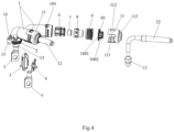
FIG. 4 shows a partially exploded view of a connector according to an embodiment of the present disclosure. -
FIG. 5 shows a fully exploded view of a connector according to an embodiment of the present disclosure. - Hereinafter, embodiments of the present disclosure will be described with reference to the accompanying drawings. The same reference numerals and symbols shown in the drawings of the present disclosure refer to elements or components performing substantially the same function.
- Furthermore, the terminology used herein is intended to describe the embodiments, and is not intended to limit and/or constrain the present disclosure. The singular forms "a", "an", "the" and "said" are intended to include the plural forms as well, unless the context clearly dictates otherwise. In the present disclosure, the terms such as "include", "comprise", "have" and the like, are intended to specify the presence of stated features, number, steps, operations, elements, components and combinations thereof, but do not preclude the presence or addition of one or more other features, number, steps, operations, elements, components and combinations thereof.
- Although the terms such as "first", "second", "third" and the like are used herein to describe various elements, these elements should not be limited by these terms. These terms are only intended to distinguish one element from another. For example, a first element would be termed a second element, and a second element would be termed a first element, without departing from the scope of the present disclosure. The term "and/or" includes a plurality of combinations of the associated items or any one of a plurality of associated items.
- In the following detailed description, for convenience of illustration, numerous specific details are set forth in order to provide a thorough understanding of the disclosed embodiments. Obviously, however, one or more embodiments may be embodied without these specific details. In other instances, well-known structures and devices are shown in schematic form in order to simplify the drawings.
- An embodiment of an aspect of the present disclosure provides a connector comprising a
housing 1 in a form of a bent tube. The housing comprises a firsttubular portion 101, a secondtubular portion 102 and abent portion 103. Thebent portion 103 is connected between the firsttubular portion 101 and the secondtubular portion 102, so that the first tubular portion and the second tubular portion extend at an angle of more than 0 degree and less than 180 degrees relative to each other. Thehousing 1 is adapted to hold acable 12 extending through the interior of the housing, so that the cable is bent within thebent portion 103. - The
housing 1 is made of conductive material, preferably metal such as aluminum alloy and stainless steel. In one embodiment, the housing is made of aluminum alloy. However, in other embodiments, the housing can also be made of non-metallic materials such as plastic. - In the illustrated embodiment, the
bent portion 103 is bent at an angle of 90 degrees, so that thecable 12 held in the housing is bent at an angle of 90 degrees inside thehousing 1. However, according to the conditions of specific applications, thebent portion 103 can be bent at an acute angle less than 90 degrees, such as 30 degrees, 45 degrees, 60 degrees, etc., or can be bent at an obtuse angle greater than 90 degrees, such as 120 degrees, 135 degrees, 150 degrees and other angles, which are not limited in this application. - As better shown in
FIGS. 3 and4 , thecable 12 adapted to be accommodated in thehousing 1 comprises aconductive core 121 and a first insulatinglayer 122 wrapped on the conductive core, and thehousing 1 is configured to allow theconductive core 121 and the first insulatinglayer 122 to extend through the interior of thehousing 1, so that the housing is electrically isolated from theconductive core 121 by the first insulatinglayer 122. - As better shown in
FIGS. 3 and4 , in one embodiment, thecable 12 can further comprises a second insulatinglayer 123 wrapped on the first insulatinglayer 122, and ashielding layer 124 located between the first insulatinglayer 122 and the second insulatinglayer 123. In the illustrated embodiment, the extension of the second insulatinglayer 123 is terminated in the firsttubular portion 101, so that theshielding layer 124 is exposed at a terminating portion of the end of the second insulatinglayer 123 and folded to be sleeved over the outer peripheral surface of the second insulatinglayer 123. - As better shown in
FIGS. 3 to 5 , the connector further comprises asheath 11 which is adapted to be sleeved over an outer peripheral surface of an end of the firsttubular portion 101 and over an outer peripheral surface of thecable 12 held in the housing, so as to hold the cable relative to the first tubular portion and prevent other components inside thehousing 1 from detaching from the housing through an opening at the end of the firsttubular portion 101. - In the illustrated embodiment, the
sheath 11 comprises anannular wall 111 adapted to be sleeved over the outer peripheral surface of the firsttubular portion 101 and acover portion 113 adapted to partially close the opening at the end of the firsttubular portion 101, and thecover portion 113 is configured to have a through hole adapted to be passed through by thecable 12. - As better shown in
FIG. 4 , anengaging opening 112 is formed in theannular wall 111, and aprotrusion 104 is formed on the outer peripheral surface of the firsttubular portion 101, and thesheath 11 is adapted to be fixed to the firsttubular portion 101 through engagement between theengaging opening 112 and theprotrusion 104. - In the illustrated preferred embodiment, the connector further comprises a
first clamping member 10 accommodated in thesheath 11, and the first clamping member comprises anannular portion 1002 adapted to be sleeved over the outer peripheral surface of thecable 12 and aflange 1001 configured to extend radially outward from theannular portion 1002. Theannular portion 1002 is adapted to be positioned between the outer peripheral surface of thecable 12 and the inner edge of the through hole of thecover portion 113 of the sheath to clamp thecable 12, thereby preventing thecable 12 from moving relative to the firsttubular portion 101. Theflange 1001 is adapted to abut against the inner surface of thecover portion 113 of the sheath, so as to prevent the first clampingmember 10 from being axially and outwardly detached from thesheath 11. - As better shown in
FIGS. 3 to 5 , in one embodiment, the connector further comprises afirst seal 9, which is tightly positioned between the inner surface of the firsttubular portion 101 and the outer peripheral surface of thecable 12 held in thehousing 1 to seal the interior of the firsttubular portion 101 from the external environment of the connector, so as to prevent foreign matters such as water and pollutants from entering the inner space of the housing of the connector. In one embodiment, theflange 1001 of the first clampingmember 10 is positioned axially between the inner surface of thecover portion 113 of thesheath 11 and thefirst seal 9. - The
sheath 11, the first clampingmember 10 and thefirst seal 9 are combined together at the end of the firsttubular portion 101 so as to fix thecable 12 held in thehousing 1, and prevent other components inside thehousing 1 from detaching from the housing through the opening at the end of the firsttubular portion 101, and hermetically separate the interior of thehousing 1 from the exterior of the connector. - In the illustrated example, the connector can further comprise shielding
rings tubular portion 101, which are adapted to contact a portion of theshielding layer 124 exposed at the terminating portion of the end of the second insulatinglayer 123. The outer surfaces of the shielding rings are adapted to contact the inner surface of the firsttubular portion 101. - The shielding rings are made of conductive material, so that the
shielding layer 124 of thecable 12 and thehousing 1 made of conductive material have the same electric potential. In addition, thehousing 1 of the connector, which is made of conductive material, is connected with a motor housing, in the illustrated example, through thelug 15 on thehousing 1 and fasteners such as bolts. As a result, theshielding layer 124 of thecable 12 and thehousing 1 of the connector have the same electric potential as the motor housing, thereby realizing the overall shielding function. - In the illustrated example, the shielding rings can comprise a
first shielding ring 8 and asecond shielding ring 7 adapted to be sleeved in the first shielding ring, wherein the portion of theshielding layer 124 exposed at the terminating portion of the end of the second insulatinglayer 123 is adapted to be tightly clamped between thefirst shielding ring 8 and thesecond shielding ring 7. - The
first shielding ring 8 comprises a first cylindrical portion and a second cylindrical portion extending in the axial direction, and the diameter of the first cylindrical portion is greater than that of the second cylindrical portion, so that the outer surface of the first cylindrical portion abuts against the inner surface of the firsttubular portion 101 , and the portion of theshielding layer 124 exposed at the terminating portion of the end of the second insulatinglayer 123 is folded over to be tightly clamped between the second cylindrical portion of thefirst shielding ring 8 and thesecond shielding ring 7, as shown inFIG. 3 . - In the illustrated preferred embodiment, the connector further comprises a
spacer 6 located in the firsttubular portion 101. An end of thespacer 6 facing thebent portion 103 is trumpet-shaped to form atrumpet portion 61. Thetrumpet portion 61 is adapted to guide thecable 12 held in the housing to extend and bend from the firsttubular portion 101 to the secondtubular portion 102 at thetrumpet portion 61, thereby preventing the first insulatinglayer 122 of thecable 12 from wearing away at thebent portion 103 of the housing and thus preventing the risk of electric leakage. - As better shown in
FIGS. 1 and2 , the exterior of the secondtubular portion 102 of thehousing 1 of the connector is provided with alug 15 in which a mountinghole 14 is formed. Preferably, thelug 15 is integrally formed with thehousing 1 of the connector. Thehousing 1 is adapted to be fixed to a motor housing by a fastener extending through the mountinghole 14 and a corresponding mounting hole of the motor housing. - As better shown in
FIGS. 3 to 5 , the connector further comprises aheat shrinkable tube 13, which is adapted to be sleeved over an outer peripheral surface of the end of the secondtubular portion 102 and an outer peripheral surface of aconnection end 1202 of thecable 12 exiting the secondtubular portion 102, so as to seal the interior of the secondtubular portion 102 from the external environment of the connector, thereby preventing foreign matters such as water and pollutants from entering the inner space of the housing of the connector, and preventing thecable 12 from moving relative to the second tubular portion102. - The connector can further comprise a
connection terminal 5 partially inserted into theheat shrinkable tube 13. The connection terminal is adapted to be electrically connected with theconnection end 1202 of thecable 12 exiting the secondtubular portion 102 and to be electrically connected to the motor. In the illustrated example, theconnection terminal 5 comprises aconnection hole 51 penetrating through the connection terminal, and thecable 12 is adapted to be fixed to and electrically connected to the motor by a bolt extending through theconnection hole 51. - As better shown in
FIGS. 3 to 5 , the connector further comprises asecond clamping member 3 and a third clamping member 4 accommodated in the secondtubular portion 102, and the second clamping member and the third clamping member are adapted to be combined together to clamp a portion of thecable 12 located inside the secondtubular portion 102, so as to fix thecable 12 relative to the secondtubular portion 102. - In the illustrated example, the dimension of the third clamping member 4 in the axial direction of the second
tubular portion 102 is smaller than the dimension of thesecond clamping member 3 in the axial direction of the secondtubular portion 102, so that thecable 12 held inside the housing is adapted to go over the third clamping member 4 to extend to thebent portion 103 of the housing and further extend into the firsttubular portion 101. - As better shown in
FIG. 3 , the connector further comprises asecond seal 2 sleeved outside the secondtubular portion 102, and the second seal is adapted to be fixed between thehousing 1 and the motor housing to prevent pollutants from entering the interior of the motor housing. - Another aspect of the present disclosure further provides a connector assembly, which comprises at least two connectors according to the above-mentioned embodiments of the present disclosure. As best shown in
FIGS. 1 to 2 , at least two connectors are fixed to each other through aconnection plate 16. - As better shown in
FIG.2 , a first tubular portion of one connector in the connector assembly and a first tubular portion of the other connector in the connector assembly are configured to form an angle relative to each other. According to the conditions of specific applications, the angle can be an acute angle less than 90 degrees, such as 30 degrees, 45 degrees, 60 degrees, etc., or an obtuse angle greater than 90 degrees, such as 120 degrees, 135 degrees, 150 degrees, etc., which are not limited in this application. In the illustrated example, a second tubular portion of the one connector in the connector assembly and a second tubular portion of the other connector in the connector assembly are parallel to each other. - The connector and the connector assembly provided by the present disclosure have a non-linear structure, so that the cable held in the connector housing can be bent and extended therein, thereby reducing space waste. In addition, it realizes a predetermined non-linear wiring direction for the cable through the connector and the connector assembly, thereby increasing product consistency and reducing rejection rate. Moreover, the connector and the connector assembly provided by various embodiments of the disclosure can further provide shielding, insulation, waterproof, electric shock prevention and other functions. The connector and connector assembly comprise fewer parts, which makes the assembly simpler and convenient and has lower cost.
- Those skilled in the art would understand that the embodiments described above are all exemplary, and those skilled in the art may improve them, and the structures described in the various embodiments may be combined optionally unless they conflict in terms of structure or principle.
- Although some embodiments of the present general inventive concept have been illustrated and described, those skilled in the art would understand that modification may be made to these embodiments without departing from the principles and spirit of the present general inventive concept. The scope of the present utility model is defined by the claims and their equivalents.
Claims (15)
- A connector, characterized by comprising a housing (1) in a form of a bent tube, wherein the housing comprises a first tubular portion (101), a second tubular portion (102) and a bent portion (103) connected between the first tubular portion and the second tubular portion, so that the first tubular portion and the second tubular portion extend at an angle of more than 0 degree and less than 180 degrees relative to each other,
wherein the housing (1) is adapted to hold a cable (12) extending through an interior of the housing, so that the cable is bent within the bent portion (103). - The connector according to claim 1, characterized in that the housing is configured to allow a conductive core (121) of the cable (12) held in the housing and a first insulating layer (122) wrapped on the conductive core (121) to extend through the interior of the housing (1), so that the housing is electrically isolated from the conductive core by the first insulating layer.
- The connector according to claim 1 or 2, characterized in that the bent portion (103) is bent at an angle of 90 degrees, so that the cable (12) held in the housing is bent at an angle of 90 degrees inside the housing (1).
- The connector according to any one of claims 1-3, characterized by further comprising a sheath (11) adapted to be sleeved over an outer peripheral surface of an end of the first tubular portion (101) and an outer peripheral surface of the cable (12) held in the housing, so as to hold the cable relative to the first tubular portion.
- The connector according to claim 4, characterized in that the sheath (11) comprises an annular wall (111) adapted to be sleeved over the outer peripheral surface of the first tubular portion (101) and a cover portion (113) adapted to partially close an opening at the end of the first tubular portion (101), and the cover portion (113) is configured to have a through hole adapted to be passed through by the cable (12),wherein an engaging opening (112) is formed in the annular wall (111), and a protrusion (104) is formed on the outer peripheral surface of the first tubular portion (101), andthe sheath (11) is adapted to be fixed to the first tubular portion (101) through engagement between the engaging opening (112) and the protrusion (104).
- The connector according to claim 5, characterized by further comprising a first clamping member (10) accommodated in the sheath (11), and the first clamping member comprises an annular portion (1002) adapted to be sleeved over the outer peripheral surface of the cable (12) and a flange (1001) configured to extend radially outward from the annular portion (1002),wherein the annular portion (1002) is adapted to be positioned between the outer peripheral surface of the cable (12) and an inner edge of the through hole of the cover portion (113) of the sheath, so as to clamp the cable, andthe flange (1001) is adapted to abut against an inner surface of the cover portion (113) of the sheath, so as to prevent the first clamping member (10) from being axially and outwardly detached from the sheath (11).
- The connector according to claim 6, characterized by further comprising a first seal (9) tightly positioned between an inner surface of the first tubular portion (101) and the outer peripheral surface of the cable (12) to seal an interior of the first tubular portion (101) from an external environment of the connector, and
the flange (1001) of the first clamping member is positioned axially between the inner surface of the cover portion (113) of the sheath and the first seal (9). - The connector according to any one of claims 2-7, characterized in that the first tubular portion is configured to allow the conductive core (121) of the cable (12), the first insulating layer (122), a second insulating layer (123) wrapped on the first insulating layer, and a shielding layer (124) located between the first insulating layer (122) and the second insulating layer (123) to extend in the first tubular portion (101),wherein extension of the second insulating layer (123) is terminated in the first tubular portion (101), so that the shielding layer (124) is exposed at a terminating portion of an end of the second insulating layer (123) and folded to be sleeved over the outer peripheral surface of the second insulating layer (123); andthe connector further comprises shielding rings (7, 8) inside the first tubular portion (101), which are adapted to contact a portion of the shielding layer (124) exposed at the terminating portion of the end of the second insulating layer (123), and an outer surface of the shielding ring is configured to contact the inner surface of the first tubular portion (101),the shielding rings comprises a first shielding ring (8) and a second shielding ring (7) adapted to be sleeved in the first shielding ring, wherein the portion of the shielding layer (124) exposed at the terminating portion of the end of the second insulating layer (123) is adapted to be tightly clamped between the first shielding ring (8) and the second shielding ring (7).
- The connector according to any one of claims 1-8, characterized by further comprising a spacer (6) located in the first tubular portion (101), an end of the spacer (6) facing the bent portion (103) is trumpet-shaped to form a trumpet portion (61), which is adapted to guide the cable (12) held in the housing to extend and bend from the first tubular portion (101) to the second tubular portion (102) at the trumpet portion (61).
- The connector according to any one of claims 1 to 9, characterized in that an exterior of the second tubular portion (102) is provided with a lug (15) in which a mounting hole (14) is formed;
wherein the housing (1) is adapted to be fixed to a motor housing by a fastener extending through the mounting hole (14) and a corresponding mounting hole of the motor housing. - The connector according to any one of claims 1 to 10, characterized by further comprising a heat shrinkable tube (13), which is adapted to be sleeved over the outer peripheral surface of the end of the second tubular portion (102) and an outer peripheral surface of a connection end (1202) of the cable (12) exiting the second tubular portion (102), so as to seal the interior of the second tubular portion (102) from the external environment of the connector.
- The connector according to claim 11, characterized by further comprising a connection terminal (5) partially inserted into the heat shrinkable tube (13), and the connection terminal is adapted to be electrically connected with the connection end (1202) of the cable (12) exiting the second tubular portion (102) and is adapted to be electrically connected to a motor,the connection terminal (5) comprises a connection hole (51) penetrating there through, andthe cable (12) is adapted to be fixed to and electrically connected to the motor by a bolt extending through the connection hole (51).
- The connector according to any one of claims 1-12, characterized by further comprising a second clamping member (3) and a third clamping member (4) accommodated in the second tubular portion (102), and the second clamping member and the third clamping member are adapted to be combined together to clamp a portion of the cable (12) located inside the second tubular portion (102), so as to fix the cable (12) relative to the second tubular portion (102).
- The connector according to any one of claims 1-13, characterized by further comprising a second seal (2) sleeved outside the second tubular portion (102), and the second seal is adapted to be fixed between the housing (1) and a motor housing to prevent pollutants from entering an interior of the motor housing.
- A connector assembly characterized by comprising at least two connectors according to any one of claims 1 to 14, andwherein the at least two connectors are fixed to each other through a connection plate (16),the first tubular portion of one connector of the at least two connectors and the first tubular portion of the other connector are configured to form an angle relative to each other, and the second tubular portion of the one connector and the second tubular portion of the other connector are parallel to each other.
Applications Claiming Priority (1)
| Application Number | Priority Date | Filing Date | Title |
|---|---|---|---|
| CN202222754357.1U CN218940221U (en) | 2022-10-19 | 2022-10-19 | Connectors and Connector Assemblies |
Publications (1)
| Publication Number | Publication Date |
|---|---|
| EP4358317A1 true EP4358317A1 (en) | 2024-04-24 |
Family
ID=86093047
Family Applications (1)
| Application Number | Title | Priority Date | Filing Date |
|---|---|---|---|
| EP23203747.3A Pending EP4358317A1 (en) | 2022-10-19 | 2023-10-16 | Connector and connector assembly |
Country Status (5)
| Country | Link |
|---|---|
| US (1) | US20240235129A9 (en) |
| EP (1) | EP4358317A1 (en) |
| JP (1) | JP2024060598A (en) |
| KR (1) | KR20240054898A (en) |
| CN (1) | CN218940221U (en) |
Citations (4)
| Publication number | Priority date | Publication date | Assignee | Title |
|---|---|---|---|---|
| GB1530707A (en) * | 1975-11-13 | 1978-11-01 | Siemens Ag | Coaxial cable connectors |
| EP1598684A2 (en) * | 2004-05-21 | 2005-11-23 | Neutrik Aktiengesellschaft | Connector mounted on a reinforced cable |
| EP2202852A2 (en) * | 2008-12-26 | 2010-06-30 | DDK Ltd. | Ground structure and electrical connector using the same |
| US10256577B2 (en) * | 2017-06-14 | 2019-04-09 | Yazaki Corporation | Connector |
Family Cites Families (6)
| Publication number | Priority date | Publication date | Assignee | Title |
|---|---|---|---|---|
| US8454385B2 (en) * | 2010-06-22 | 2013-06-04 | John Mezzalingua Associates, LLC | Coaxial cable connector with strain relief clamp |
| JP5914547B2 (en) * | 2014-02-27 | 2016-05-11 | ヒロセ電機株式会社 | connector |
| DE102015002832A1 (en) * | 2015-03-05 | 2016-09-08 | Rosenberger Hochfrequenztechnik Gmbh & Co. Kg | Method for mounting an angle connector |
| CN109361096B (en) * | 2018-10-29 | 2020-07-28 | 番禺得意精密电子工业有限公司 | Cable connector |
| CN112864697A (en) * | 2020-12-31 | 2021-05-28 | 深圳市中车业成实业有限公司 | Bending type circular connector for high-speed motor car |
| IT202100002711A1 (en) * | 2021-02-08 | 2022-08-08 | Te Connectivity Solutions Gmbh | PROTECTIVE FOAM CASING FOR REFRIGERATOR CONNECTORS |
-
2022
- 2022-10-19 CN CN202222754357.1U patent/CN218940221U/en active Active
-
2023
- 2023-10-16 EP EP23203747.3A patent/EP4358317A1/en active Pending
- 2023-10-16 JP JP2023177970A patent/JP2024060598A/en active Pending
- 2023-10-17 KR KR1020230138766A patent/KR20240054898A/en active Pending
- 2023-10-19 US US18/489,946 patent/US20240235129A9/en active Pending
Patent Citations (4)
| Publication number | Priority date | Publication date | Assignee | Title |
|---|---|---|---|---|
| GB1530707A (en) * | 1975-11-13 | 1978-11-01 | Siemens Ag | Coaxial cable connectors |
| EP1598684A2 (en) * | 2004-05-21 | 2005-11-23 | Neutrik Aktiengesellschaft | Connector mounted on a reinforced cable |
| EP2202852A2 (en) * | 2008-12-26 | 2010-06-30 | DDK Ltd. | Ground structure and electrical connector using the same |
| US10256577B2 (en) * | 2017-06-14 | 2019-04-09 | Yazaki Corporation | Connector |
Also Published As
| Publication number | Publication date |
|---|---|
| US20240136775A1 (en) | 2024-04-25 |
| JP2024060598A (en) | 2024-05-02 |
| CN218940221U (en) | 2023-04-28 |
| US20240235129A9 (en) | 2024-07-11 |
| KR20240054898A (en) | 2024-04-26 |
Similar Documents
| Publication | Publication Date | Title |
|---|---|---|
| EP0871254B1 (en) | Rotationally unrestrained grounding coupling for external grounding of fittings | |
| EP3539184B1 (en) | Connector terminal and method of assembling the same | |
| CN103636080B (en) | Shielded cable fixing structure | |
| US5354217A (en) | Lightweight connector for a coaxial cable | |
| JP5886159B2 (en) | Shield connector structure | |
| CN103415968B (en) | Shielded conductor | |
| US8747126B2 (en) | Universal ground adapter for marine cables | |
| EP2063501A1 (en) | Coaxial Cable Connector for Corrugated Cable | |
| US20120276762A1 (en) | Electrical plug connector | |
| JP2003197037A (en) | Wire harness for equipment mounting | |
| CN105144505A (en) | Terminal connecting structure for plural wiring | |
| US5410102A (en) | Cable bushing | |
| CN110611199A (en) | a wiring connector | |
| EP4358317A1 (en) | Connector and connector assembly | |
| CN210326354U (en) | Shielding sleeve crimping device | |
| CN210985043U (en) | High-voltage connector and vehicle with same | |
| EP1774622B1 (en) | Electrical connector | |
| CN220963839U (en) | Via hole connector | |
| CN210526449U (en) | Mounting bracket for connector | |
| CN210517761U (en) | Corrugated pipe fixing device | |
| CN224153925U (en) | A single-hole galvanized steel cable connector | |
| CN117080811A (en) | Via hole connector | |
| CN222691355U (en) | Explosion-proof motor outlet structure | |
| CN222581601U (en) | Sealed RF Connectors | |
| CN210111208U (en) | Connector, box and vehicle |
Legal Events
| Date | Code | Title | Description |
|---|---|---|---|
| PUAI | Public reference made under article 153(3) epc to a published international application that has entered the european phase |
Free format text: ORIGINAL CODE: 0009012 |
|
| STAA | Information on the status of an ep patent application or granted ep patent |
Free format text: STATUS: THE APPLICATION HAS BEEN PUBLISHED |
|
| AK | Designated contracting states |
Kind code of ref document: A1 Designated state(s): AL AT BE BG CH CY CZ DE DK EE ES FI FR GB GR HR HU IE IS IT LI LT LU LV MC ME MK MT NL NO PL PT RO RS SE SI SK SM TR |
|
| STAA | Information on the status of an ep patent application or granted ep patent |
Free format text: STATUS: REQUEST FOR EXAMINATION WAS MADE |
|
| 17P | Request for examination filed |
Effective date: 20241018 |
|
| RBV | Designated contracting states (corrected) |
Designated state(s): AL AT BE BG CH CY CZ DE DK EE ES FI FR GB GR HR HU IE IS IT LI LT LU LV MC ME MK MT NL NO PL PT RO RS SE SI SK SM TR |
|
| STAA | Information on the status of an ep patent application or granted ep patent |
Free format text: STATUS: EXAMINATION IS IN PROGRESS |