BACKGROUND OF THE INVENTION
-
This invention relates to an electrical connector for use in electric and electronic appliances such as servomotors, communication instruments, and the like, and more particularly to an electrical connector having a ground structure of a simple construction for grounding a cable to a shell.
-
In general, in order to obtain a ground structure of an electrical connector by an electrical continuity of a cable and a shell, a grounding contact is brought into continuity with the shell as disclosed in the following prior art, and a cable braid is connected to the grounding contact, thereby achieving the electrical continuity of the cable and the shell.
-
As examples of electrical connectors including a ground structure having a grounding contact and a shell, incorporated herein are Japanese Utility Model Application Opened No.
H4-23,083 (1992 ) (Patent Literature 1), Japanese Patent Application Opened No.
H9-115,617 (1997 ) (Patent Literature 2), and Japanese Patent Application Opened No.
2002-164,127 (Patent Literature 3).
Patent Literature 1
-
The connector disclosed in the Japanese Utility Model Application Opened No.
H4-23,083 includes a
cylindrical shell 12, an insulator 13 arranged in the
cylindrical shell 12, contacts 11 held in the insulator 13, and an
earth lug 30. The
earth lug 30 has an outwardly projecting
spring piece 36 to be in contact with the
shell 12 and an inwardly projecting
piece 35 to be in contact with one of the contacts 11 I so that the one contact I1 is electrically connected to the
shell 12.
-
The Patent Literature 1 does not disclose how to ground a cable to the shell. Moreover, the earth lug 30 is complicated in construction and is required troublesome operations for assembling the connector so that manufacturing cost of the connector would be increased.
Patent Literature 2
-
The Japanese Patent Application Opened No.
H9-115,617 discloses the receptacle connector including a conductive shell 1, a front insulator 2 and a rear insulator 3 both enclosed in the shell 1, a grounding contact 4, a plurality of contacts 5, and a
hook pin 10 having two legs 15 and a
head 16 formed with indentations 19 on its outer circumference. When the
hook pin 10 is inserted into a hole 11 of the shell 1, the
head 16 is press-fitted in a hole 11 so that the indentations 19 bite the inner surface of the hole 11, thereby securely holding the
hook pin 10. On the other hand, the legs 15 of the
hook pin 10 enter a hole 13 of the grounding contact 4 and push the inner surface of the hole 13 by elastic restoring forces of the legs 15, thereby preventing the ground contact 4 from being dislodged. The grounding contact 4 is electrically connected through the
hook pin 10 to the shell 1.
-
The Patent Literature 2 discloses the electrical continuity of the grounding contact and the shell, but does not disclose an electrical continuity of a cable braid to the shell.
Patent Literature 3
-
The electrical connector disclosed in the Japanese Patent Application Opened No.
2002-164,127 includes an
insulator 22,
contacts 24 held in the
insulator 22, a
shell 26 covering the
insulator 22, and an
earth lug 10 having at least one
contact piece 12 bent inwardly for stably contacting one of the
contact 24 and an
elastic piece 14 bent toward the
shell 26 for causing the
elastic piece 14 to contact the inner surface of the
shell 26. In this way, one
contact 24 is electrically connected through the
earth lug 10 to the
shell 26.
-
Similarly, the Patent Literature 3 does not disclose how to ground a cable to the shell 28. The earth lug 10 is also complicated in construction so that it would have the same disadvantage as that of the earth lug 30 disclosed in the Patent Literature 1.
-
There have been customers' requirements for a ground structure in which a cable is in electrical continuity with a shell. Further, there have been cases having no grounding contact. Therefore, the structures disclosed in the Patent Literature 1 to 3 could not comply with such requirements.
-
It may be envisioned that the braid of a cable is directly connected to a shell by soldering. In general, however, since the shell is covered with a surface treatment layer as by the chromate treatment, it provides an impediment to direct soldering so that removal of the surface treatment layers is needed, which is a tedious operation.
SUMMARY OF THE INVENTION
-
The invention has been completed in view of the problems with the prior art described above, and the invention has an object to provide a ground structure for grounding a cable to a shell in a simple manner without requiring troublesome operations, and further provide an electrical connector using such a ground structure.
-
The object of the invention can be accomplished by the ground structure to be connected to a cable having a plurality of cable conductors, an outer braid for covering said cable conductors, and an outer covering for covering said outer braid, according to the invention as claimed in claim 1 said ground structure comprising a folded part of said outer braid which is folded back on said outer covering, an elastic member arranged between said folded outer braid and said outer covering and having an elasticity to push said folded outer braid outwardly, and a ground member positioned on and contacting said folded outer braid and having at least one scraping and contacting means for scraping away a surface treatment layer of a shell.
-
The ground structure claimed in claim 2 is so constructed that in the ground structure claimed in claim 1, said elastic member is provided with a slit, and a plurality of said scraping and contacting means of said ground member are arranged symmetrically with respect to the center of said cable.
-
In the ground structure claimed in claim 3, said scraping and contacting means is substantially triangular pyramidal.
-
Further, the object of the invention can also be achieved by the electrical connector to be connected to a cable having a plurality of cable conductors, an outer braid for covering said cable conductors, and an outer covering for covering said outer braid, said electrical connector including a required number of contacts each having a contact portion adapted to contact a connecting object, a fixed portion to be fixed to at least one insulator, and a connection portion to be connected to the cable or a substrate, said at least one insulator for arranging and fixing said contacts, and a shell arranged to cover said at least one insulator, according to the invention of claim 4 the electrical connector constructed in that an elastic member is arranged between said outer braid and said outer covering, and a ground member is arranged on said outer braid so that said outer braid is pushed outwardly by said elastic member to bring said outer braid into contact with said ground member, and that when said ground member in contact with said outer braid is inserted into said shell, contact and scraping means of said ground member scrapes away a surface treatment layer of said shell to bring said cable into electrical continuity with said shell.
-
The electrical connector claimed in claim 5 is constructed in that said insulator consists of a front insert and a rear insert, and these front and rear inserts hold said contacts, that said shell consists of a front shell and a rear shell, and said front shell holds said front insert and said rear insert and is provided with fitting means mounted thereon for fitting with a mating connector, and that one end of said rear shell is fixed to said front shell, and the other end of said rear shell is provided with holding means for said cable.
-
In the electrical connector claimed in claim 6, said rear shell is L-shaped.
-
The electrical connector claimed in claim 7 further comprises a coupling ring as said fitting means, a BS coupling having fitting means for fixing said rear shell and.said front shell, a cable clamp as said holding means for holding said cable, and a clamp nut having fitting means for fitting with said rear shell, and upon said clamp nut-being-fitted-with said rear shell, said clamp nut holding said cable in cooperation with said cable clamp.
-
As can be seen from the above descriptions, the ground structure and the electrical connector using the same can bring about the following significant functions and effects.
- (1) The ground structure to be connected to a cable having a plurality of cable conductors, an outer braid for covering said cable conductors, and an outer covering for covering said outer braid, claimed in claim 1, comprises a folded part of said outer braid which is folded back on said outer covering, an elastic member arranged between said folded outer braid and said outer covering and having an elasticity to push said folded outer braid outwardly, and a ground member positioned on and contacting said folded outer braid and having at least one scraping and contacting means for scraping away a surface treatment layer of a shell. Therefore, the cable can be grounded to the shell in a simple manner without requiring troublesome operations.
-
(2) According to the ground structure claimed in claim 2, said elastic member is provided with a slit, and a plurality of said scraping and contacting means of said ground member are arranged symmetrically with respect to the center of said cable. Consequently, the cable can be grounded to the shell in a simple manner without requiring troublesome operations, and it is possible to cause the outer braid, the elastic member, and the ground member to contact with each other with great certainty.
-
(3) According to the ground structure claimed in claim 3, said scraping and contacting means is substantially triangular pyramidal. Accordingly, the cable can be grounded to the shell in a simple manner without requiring troublesome operations, and it is possible to cause the outer braid, the elastic member, and the ground member to positively contact with each other. The surface treatment layers of the shell can be easily removed.
-
(4) The electrical connector claimed in claim 4 is an electrical connector to be connected to a cable having a plurality of cable conductors, an outer braid for covering said cable conductors, and an outer covering for covering said outer braid, said electrical connector including a required number of contacts each having a contact portion adapted to contact a connecting object, a fixed portion to be fixed to at least one insulator, and a connection portion to be connected to the cable or a substrate, said at least one insulator for arranging and fixing said contacts, and a shell arranged to cover said at least one insulator, wherein an elastic member is arranged between said outer braid and said outer covering, and a ground member is arranged on said outer braid so that said outer braid is pushed outwardly by said elastic member to bring said outer braid into contact with said ground member, and wherein when said ground member in contact with said outer braid is inserted into said shell, contact and scraping means of said ground member scrapes away a surface treatment layer of said shell to bring said cable into electrical continuity with said shell. Therefore, the cable can be grounded to the shell in a simple manner without requiring troublesome operations, and it is possible to cause the outer braid, the elastic member, and the ground member to reliably contact with each other. The surface treatment layers of the shell can be easily removed. Accordingly, it is possible to provide an electrical connector enabling stable electrical connection.
-
(5) The electrical connector claimed in claim 5 is so constructed in that in the electrical connector said insulator consists of a front insert and a rear insert, and these front and rear inserts hold said contacts, that said shell consists of a front shell and a rear shell, and said front shell holds said front insert and said rear insert and is provided with fitting means mounted thereon for fitting with a mating connector, and that one end of said rear shell is fixed to said front shell, and the other end of said rear shell is provided with holding means for said cable. Consequently, the cable can be grounded to the shell in a simple manner without requiring troublesome operations, and it is possible to cause the outer braid, the elastic member, and the ground member to contact with each other with great certainty. The surface treatment layers of the shell can be easily removed, and therefore, it is possible to provide an electrical connector enabling stable electrical connection.
-
(6) According to the ground structure claimed in claim 6, said rear shell is L-shaped. Therefore, the cable can be grounded to the shell in a simple manner without requiring troublesome operations, and it is possible to cause the outer braid, the elastic member, and the ground member to reliably contact with each other. The surface treatment layers of the shell can be easily removed, and therefore, it is possible to provide an electrical connector enabling stable electrical connection.
-
(7) The electrical connector claimed in claim 7 comprises a coupling ring as said fitting means, a BS coupling having fitting means for fixing said rear shell and said front shell, a cable clamp as said holding means for holding said cable, and a clamp nut having fitting means for fitting with said rear shell, and upon said clamp nut being fitted with said rear shell, said clamp nut holding said cable in cooperation with said cable clamp. Accordingly, the cable can be grounded to the shell in a simple manner without requiring troublesome operations, and it is possible to cause the outer braid, the elastic member, and the ground member to contact with each other with great certainty. The surface treatment layers of the shell can be easily removed. Therefore, it is possible to provide an electrical connector enabling stable electrical connection.
-
The important aspect of the invention is the ground structure to be connected to a cable having a plurality of cable conductors, an outer braid for covering the cable conductors, and an outer covering for covering the outer braid, the ground structure comprising a folded part of the outer braid which is folded back on the outer covering, an elastic member arranged between the folded outer braid and the outer covering and having an elasticity to push the folded outer braid radially outwardly, and a ground member positioned on and contacting the folded outer braid and having at least one scraping and contacting means for scraping away a surface treatment layer of a shell.
-
In other words, in order to ground the cable to the shell in a simple manner without requiring troublesome operations, provided are a folded part of the outer braid which is folded back on the outer covering, an elastic member arranged between the folded outer braid and the outer covering and having an elasticity to push the folded outer braid radially outwardly, and a ground member positioned on and contacting the folded outer braid and having at least one scraping and contacting means for scraping away a surface treatment layer of a shell so that when the ground member in contact with the outer braid is inserted into the shell, contact and scraping means of the ground member scrapes away a surface treatment layer of the shell to bring the cable into electrical continuity with the shell.
-
The invention will be more fully understood by referring to the following detailed specification and claims taken in connection with the appended drawings.
BRIEF DESCRIPTION OF THE DRAWINGS
-
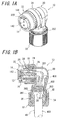
Figure 1A is a perspective view of an electrical connector according to the invention viewed from the side of fitting;
- Figure 1B is a sectional view of the electrical connector;
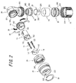
- Figure 2 is an exploded perspective view of the electrical connector showing its parts;
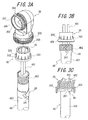
- Figure 3A is a perspective view of a rear shell, ground member, elastic member, and part of a cable;
- Figure 3B is a plan view of the elastic member combined with the cable and the ground member;
- Figure 3C is a sectional view of the combination of the rear shell, ground member, elastic member, and the cable;
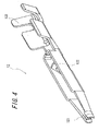
- Figure 4 is a perspective view of a contact;
- Figure 5A is a perspective view of a front insert;
- Figure 5B is a sectional view of the front insert;
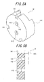
- Figure 6A is a perspective view of a rear insert;
- Figure 6B is a sectional view of the rear insert;
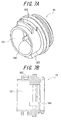
- Figure 7A is a perspective view of a plug shell (front shell);
- Figure 7B is a sectional view of the plug shell;
- Figure 8A is a perspective view of a rear shell;
- Figure 8B is a sectional view f the rear shell;
- Figure 9A is a perspective view of a coupling ring;
- Figure 9B is a sectional view of the coupling ring;
- Figure 10A is a perspective view of a BS coupling;
- Figure 10B is a sectional view of the BS coupling;
- Figure 11 is a perspective view of a cable clamp;
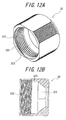
- Figure 12A is a perspective view of a clamp nut;
- Figure 12B is a sectional view of the clamp nut; and
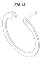
- Figure 13 is a perspective view of a retainer ring.
DESCRIPTION OF THE PREFERRED EMBODIMENTS
-
One embodiment of the electrical connector according to the invention will be explained with reference to the drawings. Figure 1A is a perspective view of the electrical connector viewed from the side of fitting, and Figure 1B is a sectional view of the electrical connector. Figure 2 is an exploded perspective view of the electrical connector showing the parts in the order of the assembling steps. Figure 3A is a perspective view of a rear shell, ground member, elastic member, and part of a cable, and Figure 3B is a plan view of the elastic member combined with the cable and the ground member, while Figure 3C is a sectional view of the combination of the rear shell, ground member, elastic member, and the cable. Figure 4 is a perspective view of a contact. Figure 5A is a perspective view of a front insert, while Figure 5B is a sectional view of the front insert. Figure 6A is a perspective view of a rear insert, while Figure 6B is a sectional view of the rear insert. Figure 7A is a perspective view of a plug shell (front shell), and Figure 7B is a sectional view of the plug shell. Figure 8A is a perspective view of the rear shell, while Figure 8B is a sectional view of the rear shell. Figure 9A is a perspective view of a coupling ring, and Figure 9B is a sectional view of the coupling ring. Figure 10A is a perspective view of a BS coupling, while Figure 10B is a sectional view of the BS coupling. Figure 11 is a perspective view of a cable clamp. Figure 12A is a perspective view of a clamp nut, and Figure 12B is a sectional view of the clamp nut. Figure 13 is a perspective view of a retainer ring.
-
The electrical connector 10 according to the invention comprises a plurality of contacts, at least one insulator, at least one shell, a cable 40, an elastic member 28, and a ground member 30. In more detail, the electrical connector according to the invention is a socket connector at least comprising a plurality of socket contacts, a front insert 14, a rear insert 16, a plug shell (front shell) 18, a rear shell 20, a coupling ring 22, a BS coupling 24, a cable clamp 26, a clamp nut 32, an elastic member 28, a ground member 30, and a retainer ring 38.
-
The cable 40 will be explained, before explaining the components of the electrical connector of the embodiment. Said cable 40 has a required number of cable conductors 401 covered by an outer braid 402 which is further covered by an outer covering 403.
-
The components of the electrical connector 10 of the present embodiment will be explained with reference to Figures 1A to 13. First, a ground structure for grounding the cable 40 to the rear shell 20 will be explained, which is a subject matter of the invention. Steps for constructing the ground structure are as follows. First, part of the outer braid 402 of the cable 40 is folded back on the outer covering 403. Second, the elastic member 28 having an elasticity is arranged between the folded outer braid 402 and the outer covering 403 so that the folded outer braid 402 is pushed radially outwardly by the elasticity of the elastic member 28. Third, arranged on the folded outer braid 402 is the ground member 30 having at least one scraping and contacting means 303 so that the ground member 30 comes into contact with the outer braid 402. Finally, the ground member 30 under the condition obtained in the third step is inserted into a through-hole 201 of the rear shell 20 so that the scraping and contacting means 303 scrapes away the surface treatment layers of the rear shell 20. In this way, said outer braid 402 of the cable 40 is brought into electrical continuity with the ground member 30, and the ground member 30 comes into electrical continuity with the rear shell 20, with the result that said cable 40 is brought into electrical continuity with said rear shell 20, thereby grounding said cable 40 to said rear shell 20.
-
The elastic member 28 will be explained. The elastic member 28 is made of a metal and formed by means of the press-working of the known technique. Preferred metals from which to form said elastic member 28 include brass, beryllium copper, phosphor bronze, and the like which comply with the requirements as to elasticity, dimensional stability, electric conductivity, and the like. Said elastic member 28 is located between the folded outer braid 402 and the outer covering 403 to push the outer braid 402 radially outwardly toward the ground member 30. The elastic member 28 is substantially cylindrical to form a receiving hole 282 for receiving the cable 40 and has a V-shaped slit 281 which provides the elasticity to the elastic member to make it possible to push the outer braid 402 radially outwardly (toward the ground member 30). The shape and size of the slit 281 may be any ones so long as the function described above is achieved and may be suitably designed in consideration of the elasticity, workability, strength, and the like. Although the slit is substantially V-shaped in the illustrated embodiment, it may be I, S, or M-shaped.
-
The ground member 30 will be explained. The ground member 30 is made of a metal and formed by means of the machining and die casting of the known technique. Preferred metals from which to form said ground member 30 generally include zinc alloy, aluminum alloy, and the like which comply with the requirements as to dimensional stability, electric conductivity, and the like. The ground member 30 is substantially cylindrical to form a receiving hole 301 for receiving therein the folded outer braid 402 (together with said cable 40). The ground member 30 is provided at one end with a flange 302 and protrusions 303 continuous therewith as said scraping and contacting means. When said ground member 30 is inserted into a through-hole 201 of said rear shell 20, the protrusions 303 scrape away chromate treatment layers of the rear shell 20 so as to come into contact with (into electrical continuity with) the rear shell 20. The shape and size of said protrusions 303 may be any ones insofar as they bring the ground member 30 into electrical continuity with the rear shell 20 to achieve the functions described above, and may be suitably designed taking into account the electrical continuity, workability, machinability, strength, and the like. The protrusions 303 are substantially triangular pyramidal in the illustrated embodiment, but they may be of substantially circular cone or cylindrical column.
-
The socket contact 12 as the contact will then be explained. The socket contact 12 is made of a metal and formed by means of the press-working of the known technique. Preferred metals from which to form said socket contact 12 include brass, beryllium copper, phosphor bronze, and the like which comply with the requirements as to dimensional stability, electric conductivity, and the like. Said socket contact 12 mainly comprises a contact portion 121 adapted to contact a mating contact of a mating connector, a fixed portion 122 to be held by two inserts 14 and 16, and a connection portion 123 to be connected to the cable. The socket contact 12 is substantially cylindrical and its contact portion 121 is also cylindrical for receiving the mating contact of the mating connector. The size of the contact portion 121 may be suitably designed to obtain the stable contact with the mating contact received in the contact portion 121. The contact 12 is firmly held in the rear insert 16 with the aid of a fixed portion 122 as a lance biting the rear insert 16. The shape and size of the fixed portion 122 may be suitably designed in consideration of the holding force for the contact, workability, the miniaturization of the electrical connector 10, and the like. Said connection portion 123 is adapted to be connected to the cable. The shape of the connection portion 123 may be suitably designed taking into account a customer's specification, an object to be connected, a method of connection, and the like. The connection portion is connected to the cable 40 by crimping in the illustrated embodiment.
-
The front insert 14 will then be explained. The front insert 14 is formed from an electrically insulating plastic material by means of the injection molding of the known technique. The materials for the front insert 14 may be suitably selected in consideration of dimensional stability, workability, manufacturing cost, and the like and generally include polybutylene terephthalate (PBT), polyamide (66PA or 46PA), liquid crystal polymer (LCP), polycarbonate (PC), polyphenylene sulfide (PPS), and the like and combination thereof. Said front insert 14 is formed with inserting holes 142 into which the socket contacts 12 are inserted, respectively. Said inserting holes 142 need only be able to hold said socket contacts 12, respectively, and the size and shape of the inserting holes 142 may be suitably designed in consideration of the size and shape of the socket contacts 12. Said front insert 14 is formed with key ways 141 on the side of fitting as shown in Figure 5A for positioning the connector 10 relatively to the mating connector. Said key ways 141 may be suitably designed so that the socket contacts 12 can be connected to mating contacts of the mating connector, respectively. In each of the inserting holes 142 on the side of fitting, moreover, there is provided a tapered guide 143 as shown in Figure 5A for guiding the mating contact into the inserting hole 142. Further, said front insert 14 is provided with fitting protrusions 144 on the side opposite from the side of fitting for positioning the front insert 14 relatively to the rear insert 16. The shape and size of said fitting protrusions 144 may be suitably designed in consideration of the function (positioning), strength, engageability upon engagement of the inserts, the size of the connector, and the like.
-
The rear insert 16 will then be explained. The rear insert 16 is formed from an electrically insulating plastic material by means of the injection molding of the known technique. The materials for the rear insert 16 may be suitably selected in consideration of dimensional stability, workability, manufacturing cost, and the like and generally include polybutylene terephthalate (PBT), polyamide (66PA or 46PA), liquid crystal polymer (LCP), polycarbonate (PC), polyphenylene sulfide (PPS), and the like and combination thereof. Said rear insert 16 is formed with inserting holes 162 into which said socket contacts 12 are inserted, respectively. Said inserting holes 162 need only be able to hold the socket contacts 12, and the size ad shape of the inserting holes 162 may be suitably designed in consideration of the size and shape of said socket contacts 12. Said rear insert 16 is provided with key ways 161 on the side of fitting (on the side of said front insert 14) as shown in Figure 6A for positioning the connector 10 relatively to the mating connector. Said key ways 161 may be suitably designed so that said socket contacts 12 can be connected to mating contacts of the mating connector. Moreover, said rear insert 16 is provided with fitting recesses 164 on the side of fitting for positioning the rear insert 16 relatively to the front insert 14. The shape and size of said fitting recesses 164 may be suitably designed taking into account the function (positioning), strength, engageability upon engagement of the inserts, the size of the connector, and the like. Further, said rear insert 16 is provided with a key recess 163 on the side opposite from the side of fitting for positioning the rear insert 16 relatively to the pug shell 18. The shape and size of said key recess 163 may be suitably designed in consideration of the function (positioning), strength, engageability upon engagement with the plug shell 18, the size of the connector, and the like.
-
The plug shell 18 as the front shell will then be explained. The plug shell 18 is made of a metal and formed by means of the machining, die casting, or the like of the known technique. Preferred metals from which to form the plug shell 18 generally include zinc alloy, aluminum alloy, and the like, and the metal of the plug shell 18 may be suitably selected from these alloys in consideration of dimensional stability, workability, manufacturing cost, and the like. Said plug shell 18 is substantially cylindrical to form a fitting hole 181 for inserting said rear insert 16 therein. Said fitting hole 181 only needs to receive said rear insert 16, and may be suitably designed in consideration of the size of said rear insert 16, workability, strength, and the like. Said plug shell 18 has holding means on its outer circumference for holding the coupling ring 22. The holding means for holding the coupling ring 22 are recesses 182 formed in the outer circumference of the plug shell 18 at predetermined positions. Projections 223 formed inside the coupling ring 22 are inserted into the recesses 182, and spring members 39 are inserted between said coupling ring 22 and end faces 183 of the plug shell 18. Further, backup spacers 35 are fitted on the spring members 39 for restraining said spring members 39, and a retainer ring 38 is fitted in an inner groove of the coupling ring 22. In this way, the coupling ring 22 is securely held. In this case, the retainer ring 38 holds the coupling ring 22 to permit it to rotate only within a predetermined angle. Moreover, the plug shell 18 is provided with an O-ring 36 to improve the waterproof property between the plug shell 18 and the rear shell 20. Moreover, an O-ring 36 is arranged in the proximity of the fitting end of the connector 10 to improve the waterproof property between the connector 10 and the mating connector. Further, said plug shell 18 is provided on the inner circumference with a key projection 184 at a location corresponding to the key recess 163 of said rear insert 16 for positioning the plug shell 18 relatively to said rear insert 16. The shape and size of said key projection 184 may be suitably designed in consideration of the function (positioning), strength, engageability upon engagement with the rear insert, the size of the connector, and the like.
-
The coupling ring 22 will then be explained. The coupling ring 22 is made of a metal and formed by means of the machining, die casting, or the like of the known technique. Preferred metals from which to form the coupling ring 22 generally include zinc alloy, aluminum alloy, and the like, and the metal of the coupling ring 22 may be suitably selected from these alloys in consideration of dimensional stability, workability, manufacturing cost, and the like.
-
Said coupling ring 22 is substantially cylindrical to form a through-hole 221 for receiving said plug shell 18. The coupling ring 22 is held on said plug shell 18 so as to be rotatable within the predetermined angle according to the method described above. The coupling ring 22 is provided with a plurality of engaging protrusions 222 inside it. When the connector 10 is engaged with the mating connector, the engaging protrusions 222 are inserted into substantially R-shaped recesses provided in the shell of the mating connector, and the engagement with the mating connector is kept by the elasticity of said spring members 39, with the result that a so-called single actuation locking means is constructed. Moreover, the coupling ring 22 is provided with the projections 223 inside of it at locations corresponding to the recesses 182 of said plug shell 18 so that the projections 223 engage the recesses 182 to hold said plug shell 18. The shape and size of said projections 223 may be suitably designed taking into account the function just described, strength, engageability upon engagement of the plug shell 18, the size of the connector, and the like.
-
The BS coupling 24 will then be explained. The BS coupling 24 is made of a metal and formed by means of the machining, die casting, or the like of the known technique. Preferred metals from which to form the BS coupling 24 generally include zinc alloy, aluminum alloy, and the like, and the metal of the BS coupling 24 may be suitably selected from these alloys in consideration of dimensional stability, workability, manufacturing cost, and the like. Said BS coupling 24 is substantially cylindrical to form a through-hole 241 for receiving said plug shell 18. The BS coupling is formed in its inner circumference with a female screw 242 which is threadedly engaged with said rear shell 20 to form fitting means for fitting said rear shell 20. In other words, said BS coupling 24 is threadedly engaged with the rear shell 20 so that said plug shell 18 is embraced by said BS coupling 24 and said rear shell 20, thereby securely fixing said rear shell 20 and said plug shell 18 to each other.
-
The rear shell 20 will then be explained. The rear shell 20 is made of a metal and formed by means of the machining, die casting, or the like of the known technique. Preferred metals from which to form the rear shell 20 generally include zinc alloy, aluminum alloy, and the like, and the metal of the rear shell 20 may be suitably selected from these alloys in consideration of dimensional stability, workability, manufacturing cost, and the like. Said rear shell 20 is treated with chromate treatment as a surface treatment for dust prevention (weather resistance). Said rear shell 20 is cylindrical but curved substantially in the form of an L-shape to form the through-hole 201 into which the cable is inserted. Said rear shell 20 is formed with an inserting portion 204 in said through-hole 201 at the end on the side of said plug shell 18 for receiving the plug shell 18. Said inserting portion 204 only needs to be able to receive said plug shell 18, and may be suitably designed in consideration of the size of said plug shell, strength, workability, and the like. Said rear shell 20 is formed with male screws 202 and 202 in outer circumferences at both the ends as fitting means for fitting said BS coupling 24 and said clamp nut 32, respectively. Moreover, said rear shell 20 is formed with engaging recesses 203 and 203 in inner circumferences at both the ends for preventing said cable clamp 26 and said plug shell 18 from being rotated relatively to the rear shell 20.
-
The cable clamp 26 will then be explained. The cable clamp 26 is formed from an electrically insulating plastic material by means of the injection molding of the known technique. The materials for the cable clamp 26 may be suitably selected in consideration of dimensional stability, workability, manufacturing cost, and the like, and generally include polybutylene terephthalate (PBT), polyamide (66PA or 46PA), liquid crystal polymer (LCP), polycarbonate (PC), polyacetal (POM), and the like and combination thereof. Said cable clamp 26 serves to hold the cable 40 when said clamp nut 32 is threadedly engaged with said rear shell 20. Said cable clamp 26 is substantially cylindrical to form a hole into which the cable 40 is inserted. Said hole may be suitably designed such that said cable can be received therein in consideration of the strength, workability, and the like. Said cable clamp 26 is formed with recesses 263 on the side contacting said rear shell 20 and formed with a plurality of comb teeth 262 each bent at one location on the side contacting said clamp nut 32. Said recesses 263 are adapted to engage the engaging recesses 203 of said rear shell 20 to prevent said cable clamp 26 from being rotated, while the bent portions of said comb teeth 262 are pushed to said cable 40 by a pushing portion 323 of said clamp nut 32 so that said cable 40 is securely held. For this purpose, the comb teeth 262 are formed by slits therebetween or the comb teeth are formed as thin independent parts to provide elasticity of respective teeth, and further the comb teeth 262 are provided at their tips with tip projections 264 to improve the holding power of the cable clamp 26 for the cable. The shape and size of said comb teeth 262 may be suitably designed taking into account the function described above, the elasticity, holding force for the cable 40, workability, and the like.
-
Finally, the clamp nut 32 will be explained. The clamp nut 32 is made of a metal or plastic material (plastic material in the illustrated embodiment) and formed by means of the machining, die casting, injection molding, and the like of the known technique. Preferred materials from which to form the clamp nut 32 generally include zinc alloy, aluminum alloy, or polybutylene terephthalate (PBT), polyamide (66PA or 46PA), liquid crystal polymer (LCP), polycarbonate (PC), polyphenylene sulfide (PPS), and the like and combination thereof, and the material of the clamp nut 32 may be suitably selected from these alloys or plastic materials in consideration of dimensional stability, workability, manufacturing cost, and the like. Said clamp nut 32 is substantially cylindrical to form a through-hole 321 into which the cable 40 is inserted. The clamp nut 32 is formed in its inner circumference with a female screw 322 adapted to be threadedly engaged with said rear shell 20 as fitting means with said rear shell 20, and is further formed with the pushing portion 323 which pushes the comb teeth 262 of said cable clamp 26 to hold said cable 40. Said pushing portion 323 only needs to be able to push the comb teeth 262- of said cable clamp 26 so as to securely hold said cable 40 and may be suitably designed taking into account the holding force for the cable 40, workability, and the like.
-
Other than the parts described above in detail, the electrical connector illustrated embodiment comprises a bushing 34, O-rings 36, retainer ring 38, and spring members 39. The O-rings 36, retainer ring 38, and spring members 39 have been briefly explained in the above description. Said bushing 34 is arranged inside said cable clamp 26 so as to closely contact said cable 40 to improve the waterproof property.
-
Although the ground structure according to the invention has been described in the case used in the socket connector having the socket contacts 12, the plug shell 18, and the like, it will be apparent that the ground structure may be used in a plug connector having plug contacts, receptacle shell, and the like. While the two inserts as insulators have been described, one or three inserts may also be used. Moreover, a straight rear shell may be used instead of the L-shaped rear shell described in the embodiment.
-
Examples of applications of the invention are electrical connectors for use in electric and electronic appliances such as servomotors, communication instruments, and the like, and more particularly electrical connectors having the ground structure of the simple construction using the cable and shells.
-
Just for confirmation, the merit of this invention can be summarized in that the ground connection to assure the electro-magnetic shielding may be accomplished during assembling the connector without particular cautions and attentions are paid at field.
-
While the invention has been particularly shown and described with reference to the preferred embodiments thereof, it will be understood by those skilled in the art that the foregoing and other changes in form and details can be made therein without departing from the spirit and scope of the invention.