EP4356035B1 - Pressverbindungssystem zum unlösbaren verbinden eines fittings und fitting - Google Patents
Pressverbindungssystem zum unlösbaren verbinden eines fittings und fitting Download PDFInfo
- Publication number
- EP4356035B1 EP4356035B1 EP22733104.8A EP22733104A EP4356035B1 EP 4356035 B1 EP4356035 B1 EP 4356035B1 EP 22733104 A EP22733104 A EP 22733104A EP 4356035 B1 EP4356035 B1 EP 4356035B1
- Authority
- EP
- European Patent Office
- Prior art keywords
- press
- fitting
- pressing
- cutting
- ring
- Prior art date
- Legal status (The legal status is an assumption and is not a legal conclusion. Google has not performed a legal analysis and makes no representation as to the accuracy of the status listed.)
- Active
Links
Images


Classifications
-
- F—MECHANICAL ENGINEERING; LIGHTING; HEATING; WEAPONS; BLASTING
- F16—ENGINEERING ELEMENTS AND UNITS; GENERAL MEASURES FOR PRODUCING AND MAINTAINING EFFECTIVE FUNCTIONING OF MACHINES OR INSTALLATIONS; THERMAL INSULATION IN GENERAL
- F16L—PIPES; JOINTS OR FITTINGS FOR PIPES; SUPPORTS FOR PIPES, CABLES OR PROTECTIVE TUBING; MEANS FOR THERMAL INSULATION IN GENERAL
- F16L13/00—Non-disconnectable pipe joints, e.g. soldered, adhesive, or caulked joints
- F16L13/14—Non-disconnectable pipe joints, e.g. soldered, adhesive, or caulked joints made by plastically deforming the material of the pipe, e.g. by flanging, rolling
- F16L13/141—Non-disconnectable pipe joints, e.g. soldered, adhesive, or caulked joints made by plastically deforming the material of the pipe, e.g. by flanging, rolling by crimping or rolling from the outside
- F16L13/142—Non-disconnectable pipe joints, e.g. soldered, adhesive, or caulked joints made by plastically deforming the material of the pipe, e.g. by flanging, rolling by crimping or rolling from the outside with a sealing element inserted into the female part before crimping or rolling
-
- B—PERFORMING OPERATIONS; TRANSPORTING
- B25—HAND TOOLS; PORTABLE POWER-DRIVEN TOOLS; MANIPULATORS
- B25B—TOOLS OR BENCH DEVICES NOT OTHERWISE PROVIDED FOR, FOR FASTENING, CONNECTING, DISENGAGING OR HOLDING
- B25B27/00—Hand tools, specially adapted for fitting together or separating parts or objects whether or not involving some deformation, not otherwise provided for
- B25B27/02—Hand tools, specially adapted for fitting together or separating parts or objects whether or not involving some deformation, not otherwise provided for for connecting objects by press fit or detaching same
- B25B27/10—Hand tools, specially adapted for fitting together or separating parts or objects whether or not involving some deformation, not otherwise provided for for connecting objects by press fit or detaching same inserting fittings into hoses
-
- F—MECHANICAL ENGINEERING; LIGHTING; HEATING; WEAPONS; BLASTING
- F16—ENGINEERING ELEMENTS AND UNITS; GENERAL MEASURES FOR PRODUCING AND MAINTAINING EFFECTIVE FUNCTIONING OF MACHINES OR INSTALLATIONS; THERMAL INSULATION IN GENERAL
- F16L—PIPES; JOINTS OR FITTINGS FOR PIPES; SUPPORTS FOR PIPES, CABLES OR PROTECTIVE TUBING; MEANS FOR THERMAL INSULATION IN GENERAL
- F16L13/00—Non-disconnectable pipe joints, e.g. soldered, adhesive, or caulked joints
- F16L13/14—Non-disconnectable pipe joints, e.g. soldered, adhesive, or caulked joints made by plastically deforming the material of the pipe, e.g. by flanging, rolling
- F16L13/141—Non-disconnectable pipe joints, e.g. soldered, adhesive, or caulked joints made by plastically deforming the material of the pipe, e.g. by flanging, rolling by crimping or rolling from the outside
-
- F—MECHANICAL ENGINEERING; LIGHTING; HEATING; WEAPONS; BLASTING
- F16—ENGINEERING ELEMENTS AND UNITS; GENERAL MEASURES FOR PRODUCING AND MAINTAINING EFFECTIVE FUNCTIONING OF MACHINES OR INSTALLATIONS; THERMAL INSULATION IN GENERAL
- F16L—PIPES; JOINTS OR FITTINGS FOR PIPES; SUPPORTS FOR PIPES, CABLES OR PROTECTIVE TUBING; MEANS FOR THERMAL INSULATION IN GENERAL
- F16L13/00—Non-disconnectable pipe joints, e.g. soldered, adhesive, or caulked joints
- F16L13/14—Non-disconnectable pipe joints, e.g. soldered, adhesive, or caulked joints made by plastically deforming the material of the pipe, e.g. by flanging, rolling
- F16L2013/145—Tools specially adapted therefor
Definitions
- the invention relates to a press connection system for the permanent connection of a fitting to a pipe, comprising a press jaw, a press contour formed on the inside of the press jaw, the press contour having a cylindrical press section, a fitting, a fitting base body, and a press sleeve forming a press chamber, a sealing ring being arranged at the proximal end of the press chamber relative to the fitting base body, and a cutting ring being arranged at the distal end of the press chamber relative to the fitting base body, and the cutting ring having a central cylindrical section, cutting elements arranged at the distal end, and cutting elements arranged at the proximal end.
- the invention also relates to an aforementioned fitting in the pressed state.
- a fitting is essentially a connecting piece for a pipeline, and a fitting is most commonly used to connect two or more pipe sections. Accordingly, the fitting preferably has two or more press sections, for example in the form of press sleeves.
- the most common fittings include straight connections, changes of direction in the form of pipe bends, reducers, branches such as T-pieces or intersections.
- a fitting can also be understood to mean a pipe connection of a valve or other component. For example, thermometers or pressure gauges, as valves, only have one connection for one pipe section. Thus, the fitting of a valve only has one press section to connect a pipe section to the valve.
- Press connections are used to connect pipe sections to fittings and other components.
- a press section of a fitting for example in the form of a press sleeve, is radially deformed inward with the pipe section inserted using a press jaw to create a permanent, tight, and permanent connection.
- a permanent connection is defined as a connection between the fitting and the pipe that can only be disassembled by at least partially destroying the connected components.
- the pressing technology used for radial forming of the pressing section primarily includes radially acting pressing systems as well as pressing systems that use radial-axial pressing, whereby a part of the fitting is displaced axially during the pressing process in order to thereby effect radial forming.
- the pipeline systems described above are primarily used to transport drinking or heating water, gas for operating a heating system, or industrial gases.
- any fluid medium can be transported in the pipelines.
- the fittings and pipes are preferably made of solid or high-strength materials, preferably of metals and alloys, in particular comprising copper, nickel and/or steel.
- the pressing jaw can be designed in different shapes.
- the pressing jaw can have two lever-shaped pressing jaw inserts with or without an additional pressing element in the shape of a wedge.
- the pressing jaw can have two, preferably rounded, pressing jaw inserts with or without an additional pressing element in the shape of a wedge.
- a pressing jaw can be designed as a pressing loop or pressing chain consisting of three or more, preferably rounded, pressing jaw inserts with or without an additional pressing element in the shape of a wedge.
- a pressing jaw typically comprises two lever-shaped pressing jaw inserts with or without an additional pressing element in the form of a wedge.
- a pressing ring can consist of two, preferably round pressing jaw inserts with or without an additional pressing element (pressing jaw without/with wedge).
- a pressing sling or pressing chain consists of 3 or more round pressing jaw inserts with or without additional pressing element (pressing jaw without/with wedge)
- a separating ring is preferably arranged between the cutting ring and the sealing ring, which creates a distance between the cutting ring and the sealing ring and prevents damage to the sealing ring by the cutting elements of the cutting ring.
- the provision of a separating ring is not necessary.
- the pressing jaw presses the pressing sleeve, and thus the sealing ring and cutting ring, radially inward at a uniform rate through a radially inward movement with the cylindrical pressing section.
- the cutting elements penetrate the pipe material to essentially the same depth.
- the penetration of the cutting elements into the pipe material fixes the pipe relative to the fitting in both axial directions.
- the penetration of the cutting elements also acts as an anti-rotation device. Securing the axial position is, among other things, necessary to prevent the permanent connection from bursting under excessive mechanical stress, whether due to excessive internal pressure of the conveyed medium or due to external mechanical influences.
- the present invention is based on the technical problem of further improving the pull-out protection and burst resistance of the pressed fitting.
- the press contour has a distal press section which is conically formed at least in sections and which adjoins the cylindrical press section and is conically formed at least in sections, and a proximal press section which is conically formed at least in sections and which adjoins the cylindrical press section, in that the distal press section is designed to radially inwardly deform the distal end of the cutting ring during radial pressing of the press sleeve, in that the cylindrical press section is designed to radially inwardly deform the proximal end of the cutting ring during radial pressing of the press sleeve, and in that the proximal press section is designed to radially inwardly deform the sealing ring during radial pressing of the press sleeve.
- the system described above results in a pressed fitting which is permanently connected to a pipe after actuation of the pressing jaw, wherein in the radially pressed state of the pressing sleeve the distal end of the cutting ring is, at least in sections, deformed inwards to a radius smaller than the radius of the proximal end of the cutting ring and wherein the distal cutting elements have, at least in sections, penetrated deeper into the pipe than the proximal cutting elements.
- the at least partially conical design of the pressing sections means that the pressing sections partially or completely assume the conical shape.
- a partial design can be with the circumferentially conical inwards directed sections.
- the pressing sleeve is then formed, at least in sections, to a smaller radius.
- the distal cutting elements In the pressed state, the distal cutting elements have penetrated, at least in sections, deeper into the pipe material than the proximal cutting elements.
- the section of the cutting ring which was cylindrical prior to pressing and on which the distal cutting elements and the proximal cutting elements are arranged or formed, is formed by the distal pressing section, which is conically shaped at least in sections, together with the cylindrical pressing section, into a conical shape tapering in the distal direction.
- the pull-out resistance of the connection between fitting and pipe is preferably also increased by aligning the distal cutting elements in the proximal direction. Since the distal cutting elements penetrate deeper into the pipe material than in conventionally pressed fittings, the pressed fitting exhibits increased resistance to pull-out forces and, in particular, to overpressure caused by the medium conveyed in the pipe.
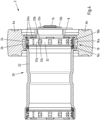
- the press connection system 2 for permanently connecting a fitting to a pipe 4 initially has a press jaw 6, which consists of two press jaw halves 6a and 6b, which are part of a pressing tool and are held by holding tabs 8 arranged on both sides, see in particular the Fig. 3 and 4 .
- Ends The retaining tabs 8 have two bores 10a and 10b, in which two axes 12a and 12b are arranged, to which the two pressing jaw halves 6a and 6b are pivotably attached.
- a further bore 14 for a fastening bolt 15 is also provided in the retaining tabs 8.
- the pressing jaw 6 is thus designed as a pressing loop, which can be compressed with a pressing tool at the open ends opposite the bore 14.
- the drive mechanism of the pressing tool is in turn operatively connected to a pressing tool, which in particular has a double roller ram with two rollers.
- the double roller ram is in particular hydraulically or electrically driven, but the drive can also be realized by a toggle lever.
- the double roller ram interacts with an inlet contour formed on the drive mechanism and presses the pressing jaw halves. apart so that the pressing jaw halves are pressed together in the area of the pressing contour.
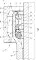
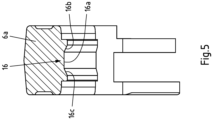
- the pressing jaw 6 with the pressing jaw halves 6a and 6b has a pressing contour 16 on the inside, which initially has a cylindrical pressing section 16a.
- the press connection system 2 has a fitting 20, wherein the fitting 20 is formed with a fitting base body 22 and a press sleeve 26 having a press chamber 24.
- a sealing ring 28 is arranged at the proximal end 30 of the press chamber 24 relative to the fitting base body 22, and a cutting ring 32 is arranged at the distal end 34 of the press chamber 24 relative to the fitting base body 22.
- a separating ring 36 is additionally arranged between the sealing ring 28 and the cutting ring 32.
- Flanged sections 26a formed circumferentially at the distal end of the press sleeve 26 serve to position the elements arranged in the press chamber 24.
- the cutting ring 32 has a central cylindrical portion 32a, cutting elements 32b arranged at the distal end and cutting elements 32c arranged at the proximal end.
- the pressing contour 16 further comprises a conical distal pressing section 16b adjacent to the cylindrical pressing section 16a and a conical proximal pressing section 16c adjacent to the cylindrical pressing section 16a.
- the distal pressing section 16b is designed to radially inwardly deform the distal end of the cutting ring 32 upon radial compression of the pressing sleeve 26 and thus of the pressing chamber 24.
- the cylindrical pressing section 16a is further designed to radially inwardly deform the proximal end of the cutting ring 32 upon radial compression of the pressing sleeve 26, and the proximal pressing section 16c is designed to radially inwardly deform the sealing ring 28 upon radial compression of the pressing sleeve 26.
- the distal outer edge 32d of the cutting ring 32 rests against the inner edge 24a of the pressing chamber 24 and the cylindrical section 32a of the cutting ring 32 rests against the cylindrical section 24b of the pressing chamber 24.
- the position of the inner edge 24a lies in the distal direction outside the edge shown by the dashed line between the cylindrical pressing section 16a and the conical distal pressing section 16b. Therefore, the distal outer edge 32d of the cutting ring 32 is deformed further radially inwards by the conical shape of the pressing section 16b than the proximal end of the cutting ring 32 is deformed by the pressing section 16a.
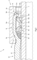
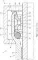
- Fig. 1 shows the condition of the press connection system 2 before pressing and Fig. 2 shows the condition of the press connection system 2 and in particular of the fitting 20 after pressing with the pipe 4.
- the cutting ring 32, the sealing ring 28, and the separating ring 36 are deformed radially inward, and the cutting elements 32b and 32c have partially penetrated the tube 4 in the region of the cutting edge. Due to the conically shaped compression section 16b and the cylindrical compression section 16a, in the radially compressed state of the compression sleeve 26, the distal end of the cutting ring 32 is deformed inward to a radius smaller than the radius of the proximal end of the cutting ring 32. As a result, the distal cutting elements 32b have penetrated the tube 4 deeper than the proximal cutting elements 32.
- Fig. 2 the penetration depths t 1 and t 2 of the cutting elements 32b and 32c are shown, and it applies that t 1 is greater than t 2.
- t 1 is greater than t 2.
- the asymmetric radial deformation is also evident from the angle between the cylindrical section 32a of the cutting ring 32 and the cylindrical section 24b of the pressing chamber 24.
- the holding force in the pull-out direction is improved, in the Fig. 1 and 2 to the right.
- the side of the cutting element 32b, with its steep cutting edge directed against the pull-out direction, contributes more to the holding force of the connection than the oblique cutting edge of the cutting element 32. Due to the tilting of the cutting ring 32 during pressing and the fact that the steep surface has a slight angle to the vertical, an additional small force component is created which pulls the cutting ring 32 towards the pipe 4. In addition, slipping of the cutting ring 32 has become less likely, because the oblique cutting edge of the cutting element 32c, due to the tilt angle of the cutting ring 32, is more likely to lift material from the pipe 4, similar to a plow.
- the fitting 20 with its elements is identical to the embodiment according to the Fig. 1 to 5
- the pressing jaw 6' has a pressing contour 16' with only one cylindrical pressing section 16a', which deforms the pressing sleeve 26 and thereby the sealing ring 28, the separating ring 28 and the cutting ring 32 radially inward in the same way. Therefore, the cutting elements 32b and the cutting elements 32c have penetrated essentially the same depth into the material of the pipe 4. This is achieved by the Fig. 7 The penetration depths t 1 and t 2 of the cutting elements 32b and 32c are clearly visible and are of equal size.
Landscapes
- Engineering & Computer Science (AREA)
- General Engineering & Computer Science (AREA)
- Mechanical Engineering (AREA)
- Quick-Acting Or Multi-Walled Pipe Joints (AREA)
- Non-Disconnectible Joints And Screw-Threaded Joints (AREA)
- Automatic Assembly (AREA)
Description
- Die Erfindung betrifft ein Pressverbindungssystem zum unlösbaren Verbinden eines Fittings mit einem Rohr, mit einer Pressbacke, mit einer an der Innenseite der Pressbacke ausgebildeten Presskontur, wobei die Presskontur einen zylindrischen Pressabschnitt aufweist, mit einem Fitting, mit einem Fittinggrundkörper und einer eine Presskammer ausbildenden Presshülse, wobei ein Dichtring am relativ zum Fittinggrundkörper proximalen Ende der Presskammer und ein Schneidring am relativ zum Fittinggrundkörper distalen Ende der Presskammer angeordnet sind und wobei der Schneidring einen mittigen zylindrischen Abschnitt, am distalen Ende angeordnete Schneidelemente und am proximalen Ende angeordnete Schneidelemente aufweist. Die Erfindung betrifft auch einen vorgenannten Fitting im verpressten Zustand.
- Der für die vorliegende Erfindung relevante technische Bereich ist die baustellenseitige Installation von Rohrleitungssystemen, bei der allgemein für das Leiten und Führen eines Fluids, also einer Flüssigkeit oder eines Gases, ein aus Rohrabschnitten und Fittings bestehendes Rohrleitungssystem installiert wird. Als Fitting wird grundsätzlich ein Verbindungsstück für eine Rohrleitung verstanden, und ein Fitting wird am häufigsten zur Verbindung von zwei oder mehreren Rohrabschnitten eingesetzt. Das Fitting weist dementsprechend bevorzugt zwei oder mehr Pressabschnitte beispielsweise in Form von Presshülsen auf. Zu den häufigsten Fittings zählen gerade Verbindungen, Richtungswechsel in Form von Rohrbögen, Reduzierstücke, Abzweige wie T-Stücke oder Kreuzungen. Unter einem Fitting ist aber auch ein Rohranschluss einer Armatur oder einer sonstigen Komponente zu verstehen. Beispielsweise weisen Thermometer oder Manometer als Armaturen nur einen Anschluss für einen Rohrabschnitt auf. Somit weist das Fitting einer Armatur nur einen Pressabschnitt auf, um einen Rohrabschnitt an der Armatur anzuschließen.
- Für das Verbinden der Rohrabschnitte mit den Fittings und sonstigen Komponenten werden Pressverbindungen genutzt, bei denen ein Pressabschnitt eines Fittings in, beispielsweise in Form einer Presshülse, bei eingestecktem Rohrabschnitt mittels einer Pressbacke radial nach innen so umgeformt wird, dass eine dauerhafte, dichte und unlösbare Verbindung hergestellt wird. Als unlösbare Verbindung wird dabei eine Verbindung zwischen Fitting und Rohr verstanden, die nur unter zumindest teilweise Zerstörung der miteinander verbundenen Komponenten auseinander genommen werden kann.
- Als Presstechnik für ein radiales Umformen des Pressabschnittes kommen vorwiegend radial wirkende Presssysteme als auch Presssysteme in Frage, die ein radial-axiales Verpressen nutzen, wobei während des Pressvorgangs ein Teil des Fittings axial verschoben wird, um dadurch ein radiales Umformen zu bewirken.
- Aus der
WO 2017/043966 A1 ist ein gattungsbildendes Pressverbindungssystem, sowie ein gattungsbildender Pressfitting bekannt. - Die zuvor allgemein beschriebenen Rohrleitungssysteme dienen insbesondere einem Transport von Trink- oder Heizungswasser, von Gas zum Betrieb einer Heizungsanlage oder von Industriegasen. Grundsätzlich kann jedes fluide Medium in den Rohrleitungen transportiert werden.
- Die Fittings und Rohre sind vorzugsweise aus festen oder hochfesten Werkstoffen hergestellt, vorzugsweise aus Metallen und aus Legierungen, insbesondere aufweisend Kupfer, Nickel und/oder Stahl.
- Die Pressbacke kann in unterschiedlicher Form ausgebildet sein. Zum einen kann die Pressbacke zwei Pressbackeneinsätze in Hebelform ohne oder mit einem zusätzlichen Presselement in Form eines Keils aufweisen. Die Pressbacke kann zum anderen zwei, vorzugsweise rundliche Pressbackeneinsätze ohne oder mit einem zusätzlichen Presselement in Form eines Keils aufweisen. Darüber hinaus kann eine Pressbacke als Pressschlinge oder Presskette bestehend aus drei oder mehr, vorzugsweise rundlichen, Pressbackeneinsätzen ohne oder mit zusätzlichen Presselement in Form eines Keils aufweisen.
- Eine Pressbacke weist üblicher Weise zwei Pressbackeneinsätze in Hebelform ohne oder mit einem zusätzlichen Presselement in Form eines Keils. Ein Pressring kann dagegen aus zwei, vorzugsweise rundliche Pressbackeneinsätzen ohne oder mit zusätzlichen Presselement (Pressbacke ohne/mit Keil)
- Eine Pressschlinge oder Presskette besteht aus 3 oder mehr rundlichen Pressbackeneinsätzen ohne oder mit zusätzlichen Presselement (Pressbacke ohne/mit Keil)
- Des Weiteren ist in bevorzugter Weise zwischen dem Schneidring und dem Dichtring ein Trennring angeordnet, der einen Abstand zwischen dem Schneidring und dem Dichtring bewerkstelligt und eine Beschädigung des Dichtrings durch die Schneidelemente des Schneidrings verhindert. Die Anordnung eines Trennrings ist aber nicht notwendig.
- Während des Verpressens drückt die Pressbacke durch eine radial einwärts gerichtet Bewegung mit dem zylindrischen Pressabschnitt die Presshülse und damit den Dichtring und den Schneidring radial gleichförmig nach innen. Somit dringen die Schneidelemente im Wesentlichen mit gleicher Tiefe in das Material des Rohrs ein.
- Das Eindringen der Schneidelemente in das Material des Rohres bewirkt ein Fixieren des Rohrs relativ zum Fitting in beiden axialen Richtungen. Zum Teil wirkt das Eindringen der Schneidelemente auch einer Drehsicherung. Die Sicherung der axialen Position ist unter anderem für die Sicherung gegenüber einem Bersten der unlösbaren Verbindung bei einer zu starken mechanischen Belastung, sei es durch einen zu hohen Innendruck des geführten Mediums oder durch eine mechanische Einwirkung von außen.
- Bei Testversuchen hat sich eine gute Belastbarkeit der bisher eingesetzten Fittings auch unter großen mechanischen Einwirkungen, beispielsweise durch Schlagversuche in axialer und radialer Richtung herausgestellt. Gleichwohl müssen die Fittings auch unter extremen Beanspruchungen bei spezifischen Anwendung standhalten.
- Daher liegt der vorliegenden Erfindung das technische Problem zugrunde, die Auszugsicherung und Berstbeständigkeit des verpressten Fittings weiter zu verbessern.
- Das zuvor aufgeführte technische Problem wird erfindungsgemäß bei einem eingangs genannten Pressverbindungssystem dadurch gelöst, dass die Presskontur einen an den zylindrischen Pressabschnitt angrenzenden, zumindest abschnittsweise, konisch ausgebildeten distalen Pressabschnitt und einen an den zylindrischen Pressabschnitt angrenzenden, zumindest abschnittsweise, konisch ausgebildeten proximalen Pressabschnitt aufweist, dass der distale Pressabschnitt ausgebildet ist, um bei einem radialen Verpressen der Presshülse das distale Ende des Schneidrings radial nach innen umzuformen, dass der zylindrische Pressabschnitt ausgebildet ist, um bei einem radialen Verpressen der Presshülse das proximale Ende des Schneidrings radial nach innen umzuformen und dass der proximale Pressabschnitt ausgebildet ist, um bei einem radialen Verpressen der Presshülse den Dichtring radial nach innen umzuformen.
- Das zuvor beschriebene System führt nach einer Betätigung der Pressbacke zu einem verpressten Fitting, der unlösbar mit einem Rohr verbunden ist, wobei im radial verpressten Zustand der Presshülse das distale Ende des Schneidrings, zumindest abschnittsweise, auf einen Radius kleiner als der Radius des proximalen Endes des Schneidrings nach innen umgeformt ist und wobei die distalen Schneidelemente, zumindest abschnittsweise, tiefer als die proximalen Schneidelemente in das Rohr eingedrungen sind.
- Die zumindest teilweise konische Ausbildung der Pressabschnitte bedeutet dabei, dass die Pressabschnitte teilweise oder vollumfänglich die konische Form annehmen. Eine teilweise Ausbildung kann dabei mit umfangseitig konisch nach innen gerichteten Abschnitten erreicht werden. Entsprechend der gänzlichen oder teilweisen Verteilung der konischen Abschnitte des Pressabschnitts wird dann die Presshülse zumindest abschnittsweise auf einen kleineren Radius umgeformt.
- Im verpressten Zustand sind die distalen Schneidelemente also, zumindest abschnittsweise, tiefer in das Material des Rohrs eingedrungen, als es für die proximalen Schneidelemente der Fall ist. Der vor dem Verpressen zylindrisch ausgebildete Abschnitt des Schneidrings, an dem die distalen Schneidelemente und die proximalen Schneidelemente angeordnet bzw. ausgebildet sind, wird dazu durch den, zumindest abschnittsweise, konisch ausgebildeten distalen Pressabschnitt zusammen mit dem zylindrischen Pressabschnitt in eine konisch sich in distaler Richtung verjüngende Form gebracht.
- Die Auszugsbeständigkeit der Verbindung zwischen Fitting und Rohr wird bevorzugt auch dadurch erhöht, dass die distalen Schneidelemente in proximaler Richtung ausgerichtet sind. Da die distalen Schneidelemente tiefer als bei herkömmlich verpressten Fittings in das Rohrmaterial eingedrungen sind, weist das verpresste Fitting eine erhöhte Beständigkeit gegenüber Auszugskräften und insbesondere gegenüber einem Überdruck auf, der durch das im Rohr geführte Medium hervorgerufen wird.
- Im Folgenden wird die Erfindung anhand eines Ausführungsbeispiels mit Bezug auf die Zeichnung erläutert. In der Zeichnung zeigen
- Fig. 1
- einen Ausschnitt eines erfindungsgemäßen Presssystems vor dem Pressvorgang,
- Fig. 2
- das in
Fig. 1 gezeigte Presssystem nach dem Pressvorgang, - Fig. 3
- das Presssystem nach
Fig. 1 in einer Seitenansicht, - Fig. 4
- das Presssystem nach
Fig. 1 im Querschnitt entlang der Linie IV-IV inFig. 3 , - Fig. 5
- das Pressprofil der Pressbacke nach
Fig. 1 - Fig. 6
- ein Presssystem nach dem Stand der Technik vor dem Pressvorgang im Querschnitt und
- Fig. 7
- das in
Fig. 6 gezeigte Presssystem nach dem Pressvorgang. - Ein erfindungsgemäßes Ausführungsbeispiel eines Pressverbindungssystems wird im Folgenden anhand der
Fig. 1 bis 5 erläutert. - Das Pressverbindungssystem 2 zum unlösbaren Verbinden eines Fittings mit einem Rohr 4 weist zunächst eine Pressbacke 6 auf, die aus zwei Pressbackenhälften 6a und 6b besteht, die Teil eines Presswerkzeugs sind und mit beidseitig angeordneten Haltelaschen 8 gehalten sind, siehe dazu insbesondere die
Fig. 3 und4 . Enden Die Haltelaschen 8 weisen zwei Bohrungen 10a und 10b auf, in denen zwei Achsen 12a und 12b angeordnet sind, an denen die beiden Pressbackenhälften 6a und 6b verschwenkbar befestigt sind. Eine weitere Bohrung 14 für einen Befestigungsbolzen 15 ist ebenfalls in den Haltelaschen 8 vorgesehen. Die Pressbacke 6 ist also als Pressschlinge ausgebildet, die an den offenen, der Bohrung 14 gegenüber liegenden Enden mit einem Presswerkzeug zusammengedrückt werden kann. - Der Antriebsmechanismus des Presswerkzeugs steht wiederum mit einem Presswerkzeug in Wirkverbindung, der insbesondere einen Doppelrollenstößel mit zwei Rollen aufweist. Der Doppelrollenstößel ist insbesondere hydraulisch oder elektrisch angetrieben, der Antrieb kann aber auch durch einen Kniehebel realisiert sein. Der Doppelrollenstößel wechselwirkt mit einer an dem Antriebsmechanismus ausgebildeten Einlaufkontur zusammen und drückt die Pressbackenhälften auseinander, so dass die Pressbackenhälften im Bereich der Presskontur zusammengedrückt werden.
- Die Pressbacke 6 mit den Pressbackenhälften 6a und 6b weist an der Innenseite eine Presskontur 16 auf, die zunächst einen zylindrischen Pressabschnitt 16a aufweist.
- Des Weiteren weist das Pressverbindungssystem 2 einen Fitting 20 auf, wobei das Fitting 20 mit einen Fittinggrundkörper 22 und einer eine Presskammer 24 aufweisenden Presshülse 26 ausgebildet ist. Innerhalb der Presskammer 24 sind ein Dichtring 28 am relativ zum Fittinggrundkörper 22 proximalen Ende 30 der Presskammer 24 und ein Schneidring 32 am relativ zum Fittinggrundkörper 22 distalen Ende 34 der Presskammer 24 angeordnet. Zwischen dem Dichtring 28 und dem Schneidring 32 ist zusätzlich noch ein Trennring 36 angeordnet. Umfangseitig am distalen Ende der Presshülse 26 ausgebildete umgebördelte Abschnitte 26a dienen dabei einer Positionierung der in der Presskammer 24 angeordneten Elemente.
- Der Schneidring 32 weist einen mittigen zylindrischen Abschnitt 32a, am distalen Ende angeordnete Schneidelemente 32b und am proximalen Ende angeordnete Schneidelemente 32c auf.
- Die Presskontur 16 weist weiterhin einen an den zylindrischen Pressabschnitt 16a angrenzenden konischen distalen Pressabschnitt 16b und einen an den zylindrischen Pressabschnitt 16a angrenzenden konischen proximalen Pressabschnitt 16c auf. Dabei ist der distale Pressabschnitt 16b ausgebildet, um bei einem radialen Verpressen der Presshülse 26 und damit der Presskammer 24 das distale Ende des Schneidrings 32 radial nach innen umzuformen. Der zylindrische Pressabschnitt 16a ist weiterhin ausgebildet, um bei einem radialen Verpressen der Presshülse 26 das proximale Ende des Schneidrings 32 radial nach innen umzuformen, und der proximale Pressabschnitt 16c ist ausgebildet, um bei einem radialen Verpressen der Presshülse 26 den Dichtring 28 radial nach innen umzuformen.
- Wie aus
Fig. 1 zu erkennen ist, liegt die distale äußere Kante 32d des Schneidrings 32 an der inneren Kante 24a der Presskammer 24 an und der zylindrische Abschnitt 32a des Schneidrings 32 am zylindrischen Abschnitt 24b der Presskammer 24 an. Die Position der inneren Kante 24a liegt dabei in distaler Richtung außerhalb der mit Hilfe der gestrichelten Linie dargestellten Kante zwischen dem zylindrischen Pressabschnitt 16a und dem konischen distalen Pressabschnitt 16b. Daher wird die distale äußere Kante 32d des Schneidrings 32 durch den konischen Verlauf des Pressabschnitts 16b weiter radial nach innen als das proximale Ende des Schneidrings 32 durch den Pressabschnitt 16a umgeformt. -
Fig. 1 zeigt den Zustand des Pressverbindungssystems 2 vor dem Verpressen undFig. 2 zeigt den Zustand des Pressverbindungssystems 2 und insbesondere des Fittings 20 nach dem Verpressen mit dem Rohr 4. - Im radial verpressten Zustand der Presshülse 26 sind der Schneidring 32 und der Dichtring 28 sowie der Trennring 36 radial nach innen umgeformt und die Schneidelemente 32b und 32c sind im Bereich der Schneidkante teilweise in das Rohr 4 eingedrungen. Aufgrund des konisch ausgebildeten Pressabschnitts 16b und des zylindrischen Pressabschnitts 16a ist im radial verpressten Zustand der Presshülse 26 das distale Ende des Schneidrings 32 auf einen Radius kleiner als der Radius des proximalen Endes des Schneidrings 32 nach innen umgeformt ist. Dadurch sind die distalen Schneidelemente 32b tiefer als die proximalen Schneidelemente 32 in das Rohr 4 eingedrungen.
- In
Fig. 2 sind die Eindringtiefen t1 und t2 der Schneidelemente 32b und 32c eingezeichnet, und es gilt, dass t1 größer als t2 ist. Die asymmetrische radiale Umformung wird auch durch den Winkel zwischen dem zylindrischen Abschnitt 32a des Schneidrings 32 und dem zylindrischen Abschnitt 24b der Presskammer 24 deutlich. - Zudem trägt aufgrund der Konstruktion der Schneidelemente 32b und 32c zur verbesserten Haltekraft in Auszugsrichtung, in den
Fig. 1 und2 nach rechts, bei. Die Seite des Schneidelements 32b wirkt mit der steil verlaufenden und gegen die Auszugsrichtung gerichteten Schneidkante mehr zur Haltekraft der Verbindung bei, als die schräg verlaufende Schneidkante des Schneidelements 32. Durch das Verkippen des Schneidrings 32 beim Verpressen und dadurch, dass die steil verlaufende Fläche einen geringen Winkel zur Senkrechten aufweist, entsteht eine zusätzliche kleine Kraftkomponente, die den Schneidring 32 zum Rohr 4 hinzieht. Zusätzlich ist ein Abrutschen des Schneidrings 32 unwahrscheinlicher geworden, denn die schräge Schneidkante des Schneidelements 32c neigt infolge des Kippwinkels des Schneidrings 32 eher zum Abheben von Material des Rohres 4, ähnlich einem Pflug. - Insgesamt wird dadurch eine verstärkte unlösbare Verbindung zwischen dem Fitting 20 und dem Rohr 4 erreicht, da die Schneidelemente 32b entgegen der Auszugsrichtung des Rohres 4 aus dem Fitting 20 heraus wirken und tiefer als im Stand der Technik in das Rohr 4 eingedrungen sind.
- Dieses wird im Vergleich des zuvor beschriebenen Ausführungsbeispiels des Pressverbindungssystem 2 nach
Fig. 1 mit dem verpressten Fitting 20 nachFig. 2 mit dem mit einem aus dem Stand der Technik bekannten und in denFig. 6 und7 dargestellten Pressverbindungssystem 2' deutlich. - Das Fitting 20 mit seinen Elementen ist identisch wie beim Ausführungsbeispiel nach den
Fig. 1 bis 5 . Die Pressbacke 6' weist jedoch eine Presskontur 16'mit nur einem zylindrischen Pressabschnitt 16a' auf, die insgesamt die Presshülse 26 und dabei den Dichtring 28, den Trennring 28 und den Schneidring 32 in gleicher Weise radial nach innen umformt. Daher sind die Schneidelemente 32b und die Schneidelemente 32c im Wesentlichen gleich tief in das Material des Rohrs 4 eingedrungen. Dieses wird durch die inFig. 7 eingezeichneten Eindringtiefen t1 und t2 der Schneidelemente 32b und 32c deutlich, die gleich groß sind.
Claims (2)
- Pressverbindungssystem (2) zum unlösbaren Verbinden eines Fittings (20) mit einem Rohr (4),- mit einer Pressbacke (6),- mit einer an der Innenseite der Pressbacke (6) ausgebildeten Presskontur (16),- wobei die Presskontur (16) einen zylindrischen Pressabschnitt (16a) aufweist,- mit einem Fitting (20),- mit einem Fittinggrundkörper (22) und einer eine Presskammer (24) ausbildenden Presshülse (26),- wobei ein Dichtring (28) am relativ zum Fittinggrundkörper (22) proximalen Ende (30) der Presskammer (24) und ein Schneidring (32) am relativ zum Fittinggrundkörper (22) distalen Ende (34) der Presskammer (24) angeordnet sind und- wobei der Schneidring (32) einen mittigen zylindrischen Abschnitt (32a), am distalen Ende angeordnete Schneidelemente (32b) und am proximalen Ende angeordnete Schneidelemente (32c) aufweist,
dadurch gekennzeichnet,- dass die Presskontur (16) einen an den zylindrischen Pressabschnitt (16a) angrenzenden, zumindest abschnittweise, konisch ausgebildeten distalen Pressabschnitt (16b) und einen an den zylindrischen Pressabschnitt (16a) angrenzenden, zumindest abschnittweise, konisch ausgebildet proximalen Pressabschnitt (16c) aufweist,- dass der distale Pressabschnitt (16b) ausgebildet ist, um bei einem radialen Verpressen der Presshülse (26) das distale Ende des Schneidrings (32) radial nach innen umzuformen,- dass der zylindrische Pressabschnitt (16a) ausgebildet ist, um bei dem radialen Verpressen der Presshülse (26) das proximale Ende des Schneidrings (32) radial nach innen umzuformen und- dass der proximale Pressabschnitt (16c) ausgebildet ist, um bei dem radialen Verpressen der Presshülse (26) den Dichtring (28) radial nach innen umzuformen. - Fitting (20) im verpressten Zustand,- mit einem Rohr (4), mit dem der Fitting (20) unlösbar verbunden ist,- mit einem Fittinggrundkörper (22) und einer eine Presskammer (24) ausbildenden Presshülse (26),- wobei ein Dichtring (28) am relativ zum Fittinggrundkörper (22) proximalen Ende (30) der Presskammer (24) und ein Schneidring (32) am relativ zum Fittinggrundkörper (22) distalen Ende (34) der Presskammer (24) angeordnet sind und- wobei der Schneidring (32) einen zylindrischen Abschnitt (32a) und am distalen Ende angeordnete Schneidelemente (32b) und am proximalen Ende angeordnete Schneidelemente (32c) aufweist,- wobei im radial verpressten Zustand der Presshülse (26) der Schneidring (32) und der Dichtring (28) radial nach innen umgeformt sind und die Schneidelemente (32b, 32c) teilweise in das Rohr (4) eingedrungen sind,
dadurch gekennzeichnet,- dass im radial verpressten Zustand der Presshülse (26) das distale Ende des Schneidrings (32), zumindest abschnittsweise, auf einen Radius kleiner als der Radius des proximalen Endes des Schneidrings (32) nach innen umgeformt ist und- dass die distalen Schneidelemente (32b), zumindest abschnittsweise, tiefer als die proximalen Schneidelemente (32c) in das Rohr (4) eingedrungen sind.
Applications Claiming Priority (2)
| Application Number | Priority Date | Filing Date | Title |
|---|---|---|---|
| DE102021115306.9A DE102021115306B4 (de) | 2021-06-14 | 2021-06-14 | Pressverbindungssystem zum unlösbaren Verbinden eines Fittings und Fitting |
| PCT/EP2022/066168 WO2022263443A1 (de) | 2021-06-14 | 2022-06-14 | Pressverbindungssystem zum unlösbaren verbinden eines fittings und fitting |
Publications (3)
| Publication Number | Publication Date |
|---|---|
| EP4356035A1 EP4356035A1 (de) | 2024-04-24 |
| EP4356035C0 EP4356035C0 (de) | 2025-04-02 |
| EP4356035B1 true EP4356035B1 (de) | 2025-04-02 |
Family
ID=82163470
Family Applications (1)
| Application Number | Title | Priority Date | Filing Date |
|---|---|---|---|
| EP22733104.8A Active EP4356035B1 (de) | 2021-06-14 | 2022-06-14 | Pressverbindungssystem zum unlösbaren verbinden eines fittings und fitting |
Country Status (4)
| Country | Link |
|---|---|
| US (1) | US12222049B2 (de) |
| EP (1) | EP4356035B1 (de) |
| DE (1) | DE102021115306B4 (de) |
| WO (1) | WO2022263443A1 (de) |
Families Citing this family (1)
| Publication number | Priority date | Publication date | Assignee | Title |
|---|---|---|---|---|
| ES2986217T3 (es) * | 2021-05-04 | 2024-11-08 | Viega Tech Gmbh & Co Kg | Sistema para conectar tubos rígidos y para conectar tubos flexibles |
Family Cites Families (8)
| Publication number | Priority date | Publication date | Assignee | Title |
|---|---|---|---|---|
| DE29721760U1 (de) | 1997-12-10 | 1998-01-29 | Franz Viegener II GmbH & Co. KG, 57439 Attendorn | Unlösbare Preßverbindung zwischen einem Fitting und einem Metallrohrende |
| DE102009007303B4 (de) | 2009-02-03 | 2023-05-04 | Viega Technology Gmbh & Co. Kg | Fitting für dickwandige Rohre |
| US8585100B2 (en) * | 2009-08-27 | 2013-11-19 | Elkhart Products Corporation | Press-connect fitting with improved grab ring function |
| NL2015413B1 (en) | 2015-09-08 | 2017-03-22 | Vsh Fittings B V | Press fitting for pipes having a check ring. |
| DE102016109034A1 (de) | 2016-05-17 | 2017-11-23 | Viega Technology Gmbh & Co. Kg | Fitting zur Herstellung einer dichten Verbindung umfassend ein Halteelement mit Kontaktflächen |
| US9664316B1 (en) | 2016-11-03 | 2017-05-30 | Quick Fitting, Inc. | Press fitting device, components and method |
| US11088515B2 (en) * | 2017-08-31 | 2021-08-10 | Eaton Intelligent Power Limited | Press fitting for electrical conduit |
| AU2018444718B2 (en) * | 2018-10-09 | 2025-05-08 | Zhuji City Howhi Air Conditioners Made Co., Ltd. | Anti-off steel ring and fixed sealing device for snap-fit pipe fitting |
-
2021
- 2021-06-14 DE DE102021115306.9A patent/DE102021115306B4/de active Active
-
2022
- 2022-06-14 WO PCT/EP2022/066168 patent/WO2022263443A1/de not_active Ceased
- 2022-06-14 US US18/569,937 patent/US12222049B2/en active Active
- 2022-06-14 EP EP22733104.8A patent/EP4356035B1/de active Active
Also Published As
| Publication number | Publication date |
|---|---|
| EP4356035A1 (de) | 2024-04-24 |
| US12222049B2 (en) | 2025-02-11 |
| EP4356035C0 (de) | 2025-04-02 |
| WO2022263443A1 (de) | 2022-12-22 |
| DE102021115306A1 (de) | 2022-12-15 |
| DE102021115306B4 (de) | 2025-09-04 |
| US20240229984A1 (en) | 2024-07-11 |
Similar Documents
| Publication | Publication Date | Title |
|---|---|---|
| EP2475922B1 (de) | Rohrleitung, rohrverschraubung und verfahren zur herstellung derselben | |
| EP0343395A2 (de) | Pressverbindungsanordnung, Armatur und Verfahren zur Herstellung | |
| DE2422409A1 (de) | Verbindungselement fuer rohrleitungen | |
| DE2219445C2 (de) | Hochdruckventil | |
| EP2565510A2 (de) | Vorrichtung zum Verbinden von Doppelmantelrohren | |
| EP2924322B1 (de) | Dichtungsvorrichtung | |
| EP2177810B1 (de) | Stopfen zum dichten Verschliessen eines Rohres | |
| DE102010038170A1 (de) | Rohrpresskupplungen, insbesondere zur Verpressung von Mehrschichtrohren, sowie Verfahren zum Herstellen einer Rohrpresskupplung | |
| DE102010044463B4 (de) | Verfahren zur Herstellung von Bimetallrohren | |
| EP4356035B1 (de) | Pressverbindungssystem zum unlösbaren verbinden eines fittings und fitting | |
| EP2636901A1 (de) | Hochdruckeinrichtung für flüssige Medien | |
| EP1845297A1 (de) | Bördelverschraubung | |
| EP3381618B1 (de) | Pressmittel zum verpressen eines fittings | |
| DE2046962A1 (de) | Gesenkschmiedbare Rohrkupplung | |
| DE60212028T2 (de) | Zufuhrrohr für Fluide unter hohem Druck | |
| DE102005047275A1 (de) | Druckrohr mit umgeformtem Anschlusskopf | |
| EP1184572B1 (de) | Addichtungsvorrichtung für einen Übergangsbereich an Hochdruckbauteilen | |
| EP1215435A1 (de) | Stopfen zur innenseitigen Rohrabdichtung | |
| DE102022115161B4 (de) | Verbindungsanordnung mit Pressverbindung | |
| DE19852861C1 (de) | Rohrpreßverbindung | |
| DE10331381A1 (de) | Pressverbindung und Stützhülse für eine Pressverbindung | |
| DE10348817B4 (de) | Rohrverbindungsschelle | |
| DE102020000308B4 (de) | Anschlussvorrichtung zum lösbaren Anschluss an eine Zugangseinheit einer Prozessleitung | |
| EP2366929B1 (de) | Anschlussstück | |
| EP1638712A1 (de) | Rohrbogen |
Legal Events
| Date | Code | Title | Description |
|---|---|---|---|
| STAA | Information on the status of an ep patent application or granted ep patent |
Free format text: STATUS: UNKNOWN |
|
| STAA | Information on the status of an ep patent application or granted ep patent |
Free format text: STATUS: THE INTERNATIONAL PUBLICATION HAS BEEN MADE |
|
| PUAI | Public reference made under article 153(3) epc to a published international application that has entered the european phase |
Free format text: ORIGINAL CODE: 0009012 |
|
| STAA | Information on the status of an ep patent application or granted ep patent |
Free format text: STATUS: REQUEST FOR EXAMINATION WAS MADE |
|
| 17P | Request for examination filed |
Effective date: 20231207 |
|
| AK | Designated contracting states |
Kind code of ref document: A1 Designated state(s): AL AT BE BG CH CY CZ DE DK EE ES FI FR GB GR HR HU IE IS IT LI LT LU LV MC MK MT NL NO PL PT RO RS SE SI SK SM TR |
|
| DAV | Request for validation of the european patent (deleted) | ||
| DAX | Request for extension of the european patent (deleted) | ||
| GRAP | Despatch of communication of intention to grant a patent |
Free format text: ORIGINAL CODE: EPIDOSNIGR1 |
|
| STAA | Information on the status of an ep patent application or granted ep patent |
Free format text: STATUS: GRANT OF PATENT IS INTENDED |
|
| INTG | Intention to grant announced |
Effective date: 20241024 |
|
| GRAS | Grant fee paid |
Free format text: ORIGINAL CODE: EPIDOSNIGR3 |
|
| GRAA | (expected) grant |
Free format text: ORIGINAL CODE: 0009210 |
|
| STAA | Information on the status of an ep patent application or granted ep patent |
Free format text: STATUS: THE PATENT HAS BEEN GRANTED |
|
| AK | Designated contracting states |
Kind code of ref document: B1 Designated state(s): AL AT BE BG CH CY CZ DE DK EE ES FI FR GB GR HR HU IE IS IT LI LT LU LV MC MK MT NL NO PL PT RO RS SE SI SK SM TR |
|
| REG | Reference to a national code |
Ref country code: GB Ref legal event code: FG4D Free format text: NOT ENGLISH |
|
| REG | Reference to a national code |
Ref country code: CH Ref legal event code: EP |
|
| REG | Reference to a national code |
Ref country code: DE Ref legal event code: R096 Ref document number: 502022003452 Country of ref document: DE |
|
| REG | Reference to a national code |
Ref country code: IE Ref legal event code: FG4D Free format text: LANGUAGE OF EP DOCUMENT: GERMAN |
|
| U01 | Request for unitary effect filed |
Effective date: 20250428 |
|
| U07 | Unitary effect registered |
Designated state(s): AT BE BG DE DK EE FI FR IT LT LU LV MT NL PT RO SE SI Effective date: 20250506 |
|
| U20 | Renewal fee for the european patent with unitary effect paid |
Year of fee payment: 4 Effective date: 20250624 |
|
| PG25 | Lapsed in a contracting state [announced via postgrant information from national office to epo] |
Ref country code: ES Free format text: LAPSE BECAUSE OF FAILURE TO SUBMIT A TRANSLATION OF THE DESCRIPTION OR TO PAY THE FEE WITHIN THE PRESCRIBED TIME-LIMIT Effective date: 20250402 |
|
| PG25 | Lapsed in a contracting state [announced via postgrant information from national office to epo] |
Ref country code: GR Free format text: LAPSE BECAUSE OF FAILURE TO SUBMIT A TRANSLATION OF THE DESCRIPTION OR TO PAY THE FEE WITHIN THE PRESCRIBED TIME-LIMIT Effective date: 20250703 Ref country code: NO Free format text: LAPSE BECAUSE OF FAILURE TO SUBMIT A TRANSLATION OF THE DESCRIPTION OR TO PAY THE FEE WITHIN THE PRESCRIBED TIME-LIMIT Effective date: 20250702 |
|
| PG25 | Lapsed in a contracting state [announced via postgrant information from national office to epo] |
Ref country code: PL Free format text: LAPSE BECAUSE OF FAILURE TO SUBMIT A TRANSLATION OF THE DESCRIPTION OR TO PAY THE FEE WITHIN THE PRESCRIBED TIME-LIMIT Effective date: 20250402 |
|
| PG25 | Lapsed in a contracting state [announced via postgrant information from national office to epo] |
Ref country code: HR Free format text: LAPSE BECAUSE OF FAILURE TO SUBMIT A TRANSLATION OF THE DESCRIPTION OR TO PAY THE FEE WITHIN THE PRESCRIBED TIME-LIMIT Effective date: 20250402 |
|
| PG25 | Lapsed in a contracting state [announced via postgrant information from national office to epo] |
Ref country code: RS Free format text: LAPSE BECAUSE OF FAILURE TO SUBMIT A TRANSLATION OF THE DESCRIPTION OR TO PAY THE FEE WITHIN THE PRESCRIBED TIME-LIMIT Effective date: 20250702 |
|
| PG25 | Lapsed in a contracting state [announced via postgrant information from national office to epo] |
Ref country code: IS Free format text: LAPSE BECAUSE OF FAILURE TO SUBMIT A TRANSLATION OF THE DESCRIPTION OR TO PAY THE FEE WITHIN THE PRESCRIBED TIME-LIMIT Effective date: 20250802 |