EP2565510A2 - Vorrichtung zum Verbinden von Doppelmantelrohren - Google Patents
Vorrichtung zum Verbinden von Doppelmantelrohren Download PDFInfo
- Publication number
- EP2565510A2 EP2565510A2 EP12178009A EP12178009A EP2565510A2 EP 2565510 A2 EP2565510 A2 EP 2565510A2 EP 12178009 A EP12178009 A EP 12178009A EP 12178009 A EP12178009 A EP 12178009A EP 2565510 A2 EP2565510 A2 EP 2565510A2
- Authority
- EP
- European Patent Office
- Prior art keywords
- pipe coupling
- coupling parts
- ring
- pipe
- welded
- Prior art date
- Legal status (The legal status is an assumption and is not a legal conclusion. Google has not performed a legal analysis and makes no representation as to the accuracy of the status listed.)
- Granted
Links
- 230000008878 coupling Effects 0.000 claims abstract description 139
- 238000010168 coupling process Methods 0.000 claims abstract description 139
- 238000005859 coupling reaction Methods 0.000 claims abstract description 139
- 238000000034 method Methods 0.000 claims abstract description 4
- 230000007704 transition Effects 0.000 claims description 17
- 238000005065 mining Methods 0.000 claims description 5
- 210000002445 nipple Anatomy 0.000 claims description 5
- 239000000725 suspension Substances 0.000 claims description 3
- 230000009977 dual effect Effects 0.000 abstract 1
- 238000004519 manufacturing process Methods 0.000 description 9
- 238000010276 construction Methods 0.000 description 3
- 238000007789 sealing Methods 0.000 description 3
- 238000003466 welding Methods 0.000 description 3
- 238000005538 encapsulation Methods 0.000 description 2
- 239000012530 fluid Substances 0.000 description 2
- 239000000314 lubricant Substances 0.000 description 2
- 230000001050 lubricating effect Effects 0.000 description 2
- 239000011343 solid material Substances 0.000 description 2
- 229910001208 Crucible steel Inorganic materials 0.000 description 1
- 208000027418 Wounds and injury Diseases 0.000 description 1
- 238000005266 casting Methods 0.000 description 1
- 239000003245 coal Substances 0.000 description 1
- 238000011109 contamination Methods 0.000 description 1
- 230000006378 damage Effects 0.000 description 1
- 238000006073 displacement reaction Methods 0.000 description 1
- 230000000694 effects Effects 0.000 description 1
- 238000005516 engineering process Methods 0.000 description 1
- 238000005246 galvanizing Methods 0.000 description 1
- 239000004519 grease Substances 0.000 description 1
- 230000001771 impaired effect Effects 0.000 description 1
- 208000014674 injury Diseases 0.000 description 1
- 238000003780 insertion Methods 0.000 description 1
- 230000037431 insertion Effects 0.000 description 1
- 238000009434 installation Methods 0.000 description 1
- 238000003754 machining Methods 0.000 description 1
- 230000001681 protective effect Effects 0.000 description 1
- 239000011241 protective layer Substances 0.000 description 1
- 230000008439 repair process Effects 0.000 description 1
- 238000005096 rolling process Methods 0.000 description 1
- 125000006850 spacer group Chemical group 0.000 description 1
- 239000007858 starting material Substances 0.000 description 1
- XLYOFNOQVPJJNP-UHFFFAOYSA-N water Substances O XLYOFNOQVPJJNP-UHFFFAOYSA-N 0.000 description 1
Images


Classifications
-
- F—MECHANICAL ENGINEERING; LIGHTING; HEATING; WEAPONS; BLASTING
- F16—ENGINEERING ELEMENTS AND UNITS; GENERAL MEASURES FOR PRODUCING AND MAINTAINING EFFECTIVE FUNCTIONING OF MACHINES OR INSTALLATIONS; THERMAL INSULATION IN GENERAL
- F16L—PIPES; JOINTS OR FITTINGS FOR PIPES; SUPPORTS FOR PIPES, CABLES OR PROTECTIVE TUBING; MEANS FOR THERMAL INSULATION IN GENERAL
- F16L39/00—Joints or fittings for double-walled or multi-channel pipes or pipe assemblies
- F16L39/005—Joints or fittings for double-walled or multi-channel pipes or pipe assemblies for concentric pipes
-
- F—MECHANICAL ENGINEERING; LIGHTING; HEATING; WEAPONS; BLASTING
- F16—ENGINEERING ELEMENTS AND UNITS; GENERAL MEASURES FOR PRODUCING AND MAINTAINING EFFECTIVE FUNCTIONING OF MACHINES OR INSTALLATIONS; THERMAL INSULATION IN GENERAL
- F16L—PIPES; JOINTS OR FITTINGS FOR PIPES; SUPPORTS FOR PIPES, CABLES OR PROTECTIVE TUBING; MEANS FOR THERMAL INSULATION IN GENERAL
- F16L3/00—Supports for pipes, cables or protective tubing, e.g. hangers, holders, clamps, cleats, clips, brackets
- F16L3/08—Supports for pipes, cables or protective tubing, e.g. hangers, holders, clamps, cleats, clips, brackets substantially surrounding the pipe, cable or protective tubing
- F16L3/12—Supports for pipes, cables or protective tubing, e.g. hangers, holders, clamps, cleats, clips, brackets substantially surrounding the pipe, cable or protective tubing comprising a member substantially surrounding the pipe, cable or protective tubing
- F16L3/1222—Supports for pipes, cables or protective tubing, e.g. hangers, holders, clamps, cleats, clips, brackets substantially surrounding the pipe, cable or protective tubing comprising a member substantially surrounding the pipe, cable or protective tubing the member having the form of a closed ring, e.g. used for the function of two adjacent pipe sections
-
- F—MECHANICAL ENGINEERING; LIGHTING; HEATING; WEAPONS; BLASTING
- F16—ENGINEERING ELEMENTS AND UNITS; GENERAL MEASURES FOR PRODUCING AND MAINTAINING EFFECTIVE FUNCTIONING OF MACHINES OR INSTALLATIONS; THERMAL INSULATION IN GENERAL
- F16L—PIPES; JOINTS OR FITTINGS FOR PIPES; SUPPORTS FOR PIPES, CABLES OR PROTECTIVE TUBING; MEANS FOR THERMAL INSULATION IN GENERAL
- F16L37/00—Couplings of the quick-acting type
- F16L37/56—Couplings of the quick-acting type for double-walled or multi-channel pipes or pipe assemblies
- F16L37/565—Concentric pipes
-
- Y—GENERAL TAGGING OF NEW TECHNOLOGICAL DEVELOPMENTS; GENERAL TAGGING OF CROSS-SECTIONAL TECHNOLOGIES SPANNING OVER SEVERAL SECTIONS OF THE IPC; TECHNICAL SUBJECTS COVERED BY FORMER USPC CROSS-REFERENCE ART COLLECTIONS [XRACs] AND DIGESTS
- Y10—TECHNICAL SUBJECTS COVERED BY FORMER USPC
- Y10T—TECHNICAL SUBJECTS COVERED BY FORMER US CLASSIFICATION
- Y10T29/00—Metal working
- Y10T29/49—Method of mechanical manufacture
- Y10T29/49826—Assembling or joining
- Y10T29/49947—Assembling or joining by applying separate fastener
- Y10T29/49966—Assembling or joining by applying separate fastener with supplemental joining
- Y10T29/49968—Metal fusion joining
Definitions
- the present invention relates to a device for connecting jacketed pipes, with two mutually corresponding pipe coupling parts and a securing element for axially connecting the pipe coupling parts, wherein the pipe coupling parts each having an inner tube to be welded to an inner ring to be welded to a casing tube outer ring and between the inner ring and the Outer ring each having a broken by a plurality of webs passage. Furthermore, the present invention relates to a method for connecting double-walled tubes by means of such a device.
- Pipe couplings Devices for connecting pipes, which are also referred to as pipe couplings, are known in many designs. Especially popular are pipe couplings, with which two pipe ends can be easily connected and disconnected without additional tools. Depending on the field of application of the piping, there are manifold requirements for the pipe couplings to be used.
- Powerful pipe couplings should allow the connected pipes in the installed state relative to each other to twist or pivot, without the flow or the function of the coupling is impaired.
- pipe couplings should also be able to be used with lines that are subjected to high pressures.
- the invention is therefore the object of the above-mentioned and previously explained in detail double pipe coupling to design and further that the known from the prior art disadvantages are avoided, that its cost-effective production and a simple assembly of the coupling is possible and that a balance of Manufacturing tolerances of the individual tubes is made possible.
- a device for connecting jacketed pipes of the type mentioned above in that at least one of the pipe coupling parts is formed divided and has two separate components, namely an inner member which is formed by the inner ring or at least this comprises and has an external thread , and an outer member which is formed by or comprises the outer ring and an inner thread corresponding to the outer thread of the inner member has, so that the outer member can be screwed onto the inner member.
- the inventive design of the pipe coupling part with two separate, screwed together components brings various advantages. This makes assembly easy. In this first, the inner ring, the split formed coupling part is welded to the associated inner tube.
- the outer component is screwed onto the inner component so far that its outer ring comes into contact with the associated jacket tube.
- the outer ring is welded to the jacket tube.
- the outer member is screwed with the outer ring on the inner member, the outer ring can always be brought to the casing pipe in abutment.
- the external thread and the internal thread are designed and positioned such that the outer component can be screwed onto the inner component so far that the outer component comes into abutment against a jacket tube to be welded when the inner component is welded to an inner tube.
- the external thread of the inner member may be longer than the corresponding internal thread of the outer member.
- a relative rotation of the pipe ends to be joined is achieved according to a further embodiment of the invention by the two pipe coupling parts are rotatably connected to each other.
- Such configured double pipe coupling allows even after closing by the securing element, that can be easily rotated about its axis welded to the one pipe coupling part piece of pipe against the adjacent and welded to the opposite pipe coupling piece pipe section. This is in some cases, e.g. for aligning a valve or when twisting pipe sections required.
- the relative movement between the fixed flanges can be achieved in particular by the use of lubricants and / or by the use of sliding or rolling bearings.
- the inner rings of the two coupling parts are pushed into one another, wherein a clearance in the axial direction is provided between the two inner rings.
- the outer rings of the two pipe coupling parts can be pushed into one another, wherein a clearance in the axial direction is provided between the two outer rings.
- the thus pre-assembled pipe coupling is positioned between the double-jacket pipes to be joined together, and the inner rings are welded to the associated inner pipes.
- the inner rings can be brought to the associated inner tubes securely in abutment, since the two pipe coupling parts are mutually displaceable.
- the associated jacket tube is brought into abutment on the outer ring of the one-piece pipe coupling part, and the two components are welded together.
- the outer component of the split-formed pipe coupling part is screwed onto the inner component so far that the outer component comes into abutment with the associated jacket pipe and the outer component can be welded to the jacket pipe.
- a further embodiment of the invention is between the inner ring of a pipe coupling part and the outer ring of the other pipe coupling part at least one ring seal - in particular in the radial direction - arranged.
- the ring seals are provided in such areas in which sufficient sealing surfaces of the corresponding pipe coupling parts are present.
- the use of a ring seal has the advantage that an excellent sealing effect can be achieved even with a relative movement between the surfaces to be sealed.
- the ring seal may be an O-ring or a radial shaft seal.
- a further embodiment of the invention provides that the two components of the pipe coupling part are rotatably connected to each other by means of at least one securing element. Due to the non-rotatable connection torsional stresses acting on the pipe coupling parts can be safely absorbed.
- a securing element is preferably a cylinder pin mounted in the axial direction, since this construction can be realized effectively and in a particularly space-saving manner.
- the securing element which axially fixes the pipe coupling parts
- a clamp is often by hand by one with a Press spring-connected clamping lever and is characterized by an easy and quick assembly and disassembly without the use of additional tools (so-called quick coupling). As a result, savings can also be realized in personnel costs.
- connection with a combination collar has the advantage that it can be transported in the closed state on the outer ring of the pipe coupling part of the sleeve piece of the pipe coupling. Furthermore, such a combination cell can also be connected to a suspension eye, since corresponding pipelines, which are often used in underground use, are usually suspended from the track construction in order to avoid deformations.
- the securing element is a union nut. Even when using a union nut no additional (impact) tools are required. Thus, the connection by hand screw together and solve. A retightening is not required after screwing the nut regularly. Often, the threaded piece and the union nut conical threads with cylindrical outlet.
- an unencapsulated thread can be used or an encapsulation by means of appropriately arranged, additional seals. The encapsulation forms a reliable protection against contamination, so that the connection can be easily solved even after long operation.
- a split pin can be provided which prevents unintentional unscrewing and increases the reliability of the double pipe coupling.
- the securing element which fixes the pipe coupling parts axially, is designed as a ball chain.
- a ball chain for axial securing a particularly low friction between the fixed flanges can be achieved, making it easy to rotate relative to each other.
- a coupling with ball chain is out of the DE 33 24 271 A1 known.
- a double nipple is arranged, which has an inner ring and a non-rotatably connected to the inner ring outer ring.
- the use of a double nipple makes it possible to design the two pipe coupling parts identically. This has the advantage that only one mold must be used, especially in casting production of pipe coupling parts, such as cast steel. In this way, the production of the pipe coupling parts can be made more economical.
- the double-pipe coupling can have a double nipple in any type of backup, especially in axial securing by a clamp, union nut or ball chain.
- the high-pressure supply line there is an operating pressure of about 40 MPa, while the return line is operated at about 4-7 MPa.
- the wall thickness of the inner high-pressure line can be selected independently of the wall thickness of the outer low-pressure or return line. For the proposed application, this may mean that the wall thickness of the inner tubes is greater than the wall thickness of the jacket tubes.
- the underground use of a double-walled tube has the advantage that in case of leakage of - due to the higher pressure - more stressed inner tube, the outer jacket tube prevents immediate leakage of fluid from the double-jacket tube. This reduces the risk of injury and, in particular in mining, can thus avoid unnecessary repairs in hard-to-reach areas.
- spacers are mounted between the inner tubes and the jacket tubes at predetermined intervals, which - comparable to the fixed flanges - radially spaced both tubes.
- the transitions between the webs of a pipe coupling part or both pipe coupling parts are rounded in their transition region to the associated inner ring and / or outer ring.
- the webs can be rounded at their end face pointing to the coupling outer side both in the transition region to the outer ring and in the transition region to the inner ring and in particular form an approximately part-circular curvature.
- the webs of the one-piece pipe coupling part can be rounded only at their transition to the inner ring.
- the webs may be rounded at its facing the clutch inner side end face and / or on its side facing the clutch outer face in the transition region to the outer ring. A rounding to the inner ring is out of the question, since the screwing between the inner and the outer component takes place here.
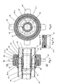
- Fig. 1 shows a device for connecting double-jacket pipes, which is also referred to below as a double-pipe coupling.
- the illustrated double-pipe coupling essentially has two pipe coupling parts 1, 2 and a securing element for the axial connection of the pipe coupling parts 1, 2.
- the pipe coupling parts 1, 2 each have an inner ring 1i and 2i and an outer ring 1a and 2a, wherein each of the inner rings 1i and 2i has a weld-on end 3 and 4 respectively and each of the outer rings 1a and 2a has a weld-on end 3 and 4, respectively.
- About the Ansch healthenden 3, 4, 5, 6, the pipe coupling parts 1, 2 to the ends of each of an inner tube 7, 8 and a jacket tube 9, 10 are welded.
- the inner tubes 7, 8 and the jacket tubes 9, 10 are arranged substantially collinear, so that between the inner tube 7 and the jacket tube 9 and between the inner tube 8 and the jacket tube 10 in each case an unspecified annular space is formed.
- FIG. 1 right-hand pipe coupling part 2 of two separate components, namely an inner component, which is essentially formed by the inner ring 1i of the pipe coupling part 1, and an outer member which is formed by the outer ring 1a with the webs 11 and the passages 12.
- the outer component is screwed onto the inner component.
- the inner ring 1i has an external thread 13 and the outer component has a corresponding internal thread 14.
- the external thread 13 is formed longer than the corresponding internal thread 14.
- the two pipe coupling parts 1, 2 are connected together in a conventional manner by a clamp 16 which is placed around the pipe coupling parts 1, 2 and the radial protruding paragraphs of the pipe coupling parts 1, 2 surrounds to fix the pipe coupling parts 1, 2 axially to each other.
- the inner rings 1i, 2i of the two pipe coupling parts 1, 2 are pushed into one another, wherein between the two inner rings 1i, 2i a game S is provided in the axial direction.
- the outer rings 1a, 2a of the two pipe coupling parts 1, 2 are pushed into one another, wherein between the two outer rings 1a, 2a a game in the axial direction remains.
- the annular gaps between the inner rings 1i, 2i and the outer rings 1a, 2a are sealed by corresponding annular seals 15.
- the two pipe coupling parts 1, 2 are put together. Subsequently, the two inner rings 1i, 2i are welded in the region of their welding ends 3, 4 to the associated inner tubes 7, 8.
- the inner rings 1i, 2i can be positioned exactly on the inner tubes 7, 8, since the two tube coupling parts 1, 2 are axially displaceable relative to one another. Subsequently, the left in the drawing casing 10 is brought to the stop on the one-piece pipe coupling part 2. Now, the outer member with the outer ring 1a of the two-part pipe coupling part 1 relative to the inner ring 1i so far twisted until it comes to the right in the drawing casing 9 in abutment. Finally, the welds between the jacket tubes 9, 10 and the welds 5, 6 of the outer rings 1a, 2a are produced.
- FIGS. 3 and 4 show a similar construction of a double pipe coupling, wherein instead of the clamp 16 a combination collar 36 is used.
- the use of a combination bowl has the advantage that it is held in a form-fitting manner during transport on the outer ring 22a and indeed in a circumferential groove 37.
- the combination cell 36 has two clamp halves 36A and 36B, which is folded around in a fixed position around the outer ring 22a (and 21a).
- Out Fig. 4 shows that in the upper part of the clamp half 36A a suspension lug 38 is arranged in order to suspend the pipe provided with the double pipe coupling according to the invention, for example when used in underground mining.
- FIGS. 5 and 6 and FIGS. 7 and 8 show two alternatives of a double-pipe coupling, in which the two outer rings 41a, 42a and 41a ', 42a' are each fixed by a union nut 56 or 56 'with threads 57 and 57' in the axial direction.
- the assembly and disassembly of the invention and in the FIGS. 5 and 6 shown double pipe coupling allows a connection by hand, since the thread 57 of the cap nut 56 is formed conically with a cylindrical structure.
- the use of a union nut 56 'with a cylindrical thread 57' requires for assembly / disassembly, however, always a striking tool.
- the illustrated union nuts 56, 56 ' have radially projecting webs 58 and 58', but it is also possible, although not shown, that the union nuts can also be provided with corresponding radial blind holes to be closed or opened by means of a corresponding tool to become. In this case, however, the pipe coupling thus equipped builds significantly smaller than with the projecting webs 58 and 58 '.
- the inner ring 41i 'and the associated outer ring 41a' of the pipe coupling part 41 ' can be rotatably connected together in the desired position, for example by the use of a cylinder pin 49 shown in the axial direction shown in the axial direction.
- a non-rotatable connection is in particular then required if additional torsional moments are introduced into the screw, as for example in the embodiment according to the FIGS. 7 and 8 the case is.
- the embodiment with the cylindrical pin 49 is particularly well from the detailed representation according to Fig. 7A out.
- a single ball chain 76 is provided as an axial securing element.
- a common circumferential groove 77 is incorporated, in which the ball chain 76 is inserted to prevent axial displacement of the two pipe coupling parts 61 and 62.
- the insertion and withdrawal of the ball chain 76 is particularly simple if a two-piece ball chain 76, so a ball chain 76 is used with two loose ends. This is introduced through an opening 78 in the groove 77, wherein an assembly aid 79 in the region of the recess 78 ensures the proper position.
- the chain links of the ball chain 76 may be balls, rollers, discs, cylinders or the like.
- the recess 78 can be covered with a protective clip 80, which is particularly clear Fig. 10 can be seen. It is not shown that the circumferential groove 77 can also be acted upon by means of a correspondingly arranged lubricating nipple with lubricant, in particular lubricating grease, in order to simplify the subsequent removal of the ball chain 76 from the double-tube coupling.
- FIG. 11 another embodiment of a double pipe coupling according to the invention shown.
- This essentially corresponds to the one in FIG. 5 illustrated embodiment.
- the difference is only in the configuration of the webs 51, 51 a of the pipe coupling parts 41, 42.
- the webs 51 a of the integrally formed pipe coupling part 42 at its coupling to the outside, ie to the left-facing side in the transition to the outer ring 42 a and the inner ring 42 i to form a part-circular curvature W formed rounded.
- the webs 51a are rounded off at their side facing the clutch inner side right side in their transition to the inner ring 42i. Because the Webs complete 51a on its inwardly facing side flush with the outer ring 42a, here the transition is rectilinear.
- the webs 51 of the two-part right pipe coupling part 41 are rounded at its inwardly facing end face and at its outwardly facing end face in the transition to the outer ring 41 a. Since the outer component of the two-part pipe coupling part 41 is screwed onto the inner ring 41i with the outer ring 41a and the webs 51, rounded transitions are not possible here.
Abstract
Description
- Die vorliegende Erfindung betrifft eine Vorrichtung zum Verbinden von Doppelmantelrohren, mit zwei miteinander korrespondierenden Rohrkupplungsteilen und einem Sicherungselement zum axialen Verbinden der Rohrkupplungsteile, wobei die Rohrkupplungsteile jeweils einen mit einem Innenrohr zu verschweißenden Innenring, einen mit einem Mantelrohr zu verschweißenden Außenring und zwischen dem Innenring und dem Außenring jeweils einen durch eine Mehrzahl von Stegen unterbrochenen Durchlass aufweisen. Des Weiteren betrifft die vorliegende Erfindung ein Verfahren zum Verbinden von Doppelmantelrohren mittels einer solchen Vorrichtung.
- Vorrichtungen zum Verbinden von Rohren, die auch als Rohrkupplungen bezeichnet werden, sind in vielfältigen Ausführungen bekannt. Besonders beliebt sind Rohrkupplungen, mit denen zwei Rohrenden ohne zusätzliche Werkzeuge leicht verbunden und wieder voneinander gelöst werden können. Je nach Einsatzgebiet der Rohrleitungen stellen sich vielfältige Anforderungen an die zu verwendenden Rohrkupplungen.
- Leistungsfähige Rohrkupplungen sollen es erlauben, die verbundenen Rohre auch im verlegten Zustand relativ zueinander zu verdrehen oder zu verschwenken, ohne dass die Durchströmung oder die Funktion der Kupplung beeinträchtigt wird. Zudem sollen Rohrkupplungen auch bei Leitungen verwendet werden können, die mit hohen Drücken beaufschlagt werden.
- Auch bei Leitungen, bei denen zwei Rohre im Wesentlichen koaxial ineinander verlaufen, werden Rohrkupplungen eingesetzt. Solche Leitungen sind unter der Bezeichnung Doppelrohr oder auch Doppelmantelrohr bekannt.
- Aus der
DE 10 2009 052 674 A1 ist eine gattungsgemäße Rohrkupplung für Doppelmantelrohre bekannt. Die gezeigte Rohrkupplung sieht die Verbindung zweier ineinander liegender Rohrleitungen vor. Dabei befindet sich im Inneren eine Hochdruckleitung, die für Drücke bis etwa 400 bar ausgelegt ist, wohingegen das äußere Rohr als Rücklaufleitung genutzt wird (mit Drücken von etwa 40 bis 70 bar). Um eine solche Verbindung im Zusammenhang mit den notwendigen Rohren fertigungstechnisch realisieren zu können, ist eine Schiebehülse ("Teleskoprohr") vorgesehen, die nach dem Verschweißen des Innenrohrs die Verbindung zwischen dem außenliegenden Rohr und dem Rohrkupplungsteil herstellt. - Ein solcher Aufbau weist insbesondere unter fertigungstechnischen Aspekten zahlreiche Nachteile auf. Die Schiebehülse stellt ein zusätzliches Bauteil dar, welches notwendig ist, um die verschiedenen Schweißverbindungen realisieren zu können, und um Längentoleranzen der Rohre auszugleichen. Infolge dessen sind für die Fertigung eines Rohres mit den entsprechenden Rohrkupplungsteilen fünf Schweißverbindungen erforderlich. Zwischen der Schiebehülse und dem innen befindlichen äußeren Rohr besteht zudem die Gefahr eines verstärkten korrosiven Angriffs, da eine entsprechende Schutzschicht (beispielsweise Verzinkung) in diesem Bereich nicht aufgebracht werden kann. Die einteilig ausgeführten Rohrkupplungsteile besitzen darüber hinaus sehr große Abmessungen, weswegen als Ausgangsmaterial für die spanende Bearbeitung häufig Vollmaterial gewählt werden muss, da dickwandige Rohre in diesem Größenbereich nicht verfügbar sind. Neben dem hohen fertigungstechnischen Aufwand zur Bearbeitung dieses Vollmaterials treten auch hohe Kosten auf.
- Der Erfindung liegt daher die Aufgabe zugrunde, die eingangs genannte und zuvor näher erläuterte Doppelrohrkupplung so auszugestalten und weiterzubilden, dass die aus dem Stand der Technik bekannten Nachteile vermieden werden, dass seine kostengünstige Herstellung sowie eine einfache Montage der Kupplung möglich ist und dass ein Ausgleich von fertigungstechnischen Längentoleranzen der einzelnen Rohre ermöglicht wird.
- Diese Aufgabe wird bei einer Vorrichtung zum Verbinden von Doppelmantelrohren der eingangs genannten Art dadurch gelöst, dass wenigstens eines der Rohrkupplungsteile geteilt ausgebildet ist und zwei separate Bauteile aufweist, nämlich ein inneres Bauteil, welches durch den Innenring gebildet wird oder diesen zumindest umfasst und ein Außengewinde aufweist, und ein äußeres Bauteil, welches von dem Außenring gebildet wird oder diesen umfasst und ein zu dem Außengewinde des inneren Bauteils korrespondierendes Innengewinde aufweist, sodass das äußere Bauteil auf das innere Bauteil aufgeschraubt werden kann. Die erfindungsgemäße Ausgestaltung des Rohrkupplungsteils mit zwei getrennten, miteinander verschraubbaren Bauteilen bringt verschiedene Vorteile mit sich. So gestaltet sich die Montage einfach. Bei dieser wird zunächst der Innenring das geteilt ausgebildeten Kupplungsteils an dem zugehörigen Innenrohr festgeschweißt. Anschließend wird das äußere Bauteil auf das innere Bauteil soweit aufgeschraubt, dass sein Außenring an dem zugehörigen Mantelrohr in Anlage kommt. Abschließend wird der Außenring an dem Mantelrohr festgeschweißt. Dadurch, dass das äußere Bauteil mit dem Außenring auf das innere Bauteil aufgeschraubt wird, kann der Außenring immer an dem Mantelrohr in Anlage gebracht werden. Insbesondere ist es möglich, Längentoleranzen, die auch mehrere Millimeter betragen können, auszugleichen. Hierzu sind das Außengewinde und das Innengewinde derart ausgebildet und positioniert, dass das äußere Bauteil so weit auf das innere Bauteil aufgeschraubt werden kann, dass das äußere Bauteil an einem anzuschweißenden Mantelrohr in Anlage kommt, wenn das innere Bauteil an einem Innenrohr festgeschweißt ist. Insbesondere kann das Außengewinde des inneren Bauteils länger sein als das entsprechende Innengewinde des äußeren Bauteils.
- Da im drucklosen Zustand ein gewisses Gewindespiel vorhanden ist, ergeben sich insbesondere im untertägigen Einsatz weitere Vorteile aufgrund der Möglichkeit, dass das Gewindespiel Toleranzen, insbesondere der Konzentrizität der beiden Dichtsitze, ausgleicht. Des Weiteren kann das äußere Rohr Zugspannungen des inneren Rohrs teilweise übernehmen und stellt einen zusätzlichen Knickschutz dar, da es eine zusätzliche Stabilität verleiht und somit die kritische Knicklänge beeinflusst. Das äußere Rohr (Rücklaufrohr), das üblicherweise aus S235 besteht, hat eine höhere Bruchdehnung als das innere Rohr (Hochdruckrohr), welches üblicherweise aus S355 besteht. Somit ist selbst bei einem Versagen des Hochdruckrohres die Rohrleitung nach außen noch dicht, da das Rücklaufrohr noch eine bestimmte Zeit plastisch verformt werden kann, bevor es versagt. In einem solchen Zeitraum findet bereits ein Druckabfall im Hochdruckbereich statt, so dass durch die Anordnung ineinander liegender Rohrleitungen die Sicherheit gegenüber dem kompletten Versagen der Rohrleitung mit der Gefahr eines Austritts der Hydraulikflüssigkeit unter hohem Druck deutlich erhöht wird.
- Eine Relativdrehung der zu verbindenden Rohrenden wird nach einer weiteren Ausgestaltung der Erfindung erreicht, indem die beiden Rohrkupplungsteile drehbar miteinander verbunden sind. Eine derart ausgestaltete Doppelrohrkupplung ermöglicht es auch noch nach dem Schließen durch das Sicherungselement, dass sich das an dem einen Rohrkupplungsteil angeschweißte Rohrstück gegen das benachbarte und am gegenüberliegenden Rohrkupplungsteil angeschweißte Rohrstück leicht um seine Achse drehen lässt. Dies ist in einigen Fällen, z.B. zum Ausrichten einer Armatur oder beim Verdrehen von Rohrleitungsabschnitten, erforderlich. Die Relativbewegung zwischen den Festflanschen kann insbesondere durch den Einsatz von Schmierstoffen und/oder durch den Einsatz von Gleit- oder Wälzlagern erreicht werden.
- Gemäß einer Ausführungsform der Erfindung sind die Innenringe der beiden Kupplungsteile ineinander geschoben, wobei zwischen den beiden Innenringen ein Spiel in axialer Richtung vorgesehen ist. Alternativ oder zusätzlich können die Außenringe der beiden Rohrkupplungsteile ineinander geschoben sein, wobei zwischen den beiden Außenringen ein Spiel in axialer Richtung vorgesehen ist. Bei der Montage einer solchen Rohrkupplung bzw. Vorrichtung zum Verbinden von Doppelmantelrohren wird zunächst das geteilt ausgebildete Rohrkupplungsteil vormontiert, indem das äußere Bauteil auf das innere Bauteil geschraubt wird. Anschließend werden die Innenringe und Außenringe der beiden Rohrkupplungsteile zusammengesteckt, sodass zwischen den Innenringen einerseits und den Außenringen andererseits ein axiales Spiel verbleibt. Die so vormontierte Rohrkupplung wird zwischen den miteinander zu verbindenden Doppelmantelrohren positioniert, und die Innenringe werden an den zugeordneten Innenrohren festgeschweißt. Dabei können die Innenringe an den zugeordneten Innenrohren sicher in Anlage gebracht werden, da die beiden Rohrkupplungsteile gegeneinander verschieblich sind. Anschließend wird an dem Außenring des einteiligen Rohrkupplungsteils das zugeordnete Mantelrohr in Anschlag gebracht, und die beiden Bauteile werden miteinander verschweißt. Abschließend wird das äußere Bauteil des geteilt ausgebildeten Rohrkupplungsteils auf das innere Bauteil soweit aufgeschraubt, dass das äußere Bauteil an dem zugeordneten Mantelrohr in Anlage kommt und das äußere Bauteil an dem Mantelrohr festgeschweißt werden kann.
- Wie bereits ausgeführt dient die Verschraubung der beiden Bauteile, welche das eine Rohrkupplungsteil aufweist, zum Ausgleich von Längentoleranzen beim Mantelrohr. Durch das axiale Spiel zwischen den beiden Innenringen und/oder den beiden Außenringen wird eine weitere Möglichkeit zum Längenausgleich geschaffen.
- In weiterer Ausgestaltung der Erfindung ist zwischen dem Innenring des einen Rohrkupplungsteils und dem Außenring des anderen Rohrkupplungsteils wenigstens eine Ringdichtung - insbesondere in radialer Richtung - angeordnet. Dabei versteht sich von selbst, dass die Ringdichtungen in solchen Bereichen vorgesehen sind, in denen ausreichende Dichtflächen der korrespondierenden Rohrkupplungsteile vorhanden sind. Der Einsatz einer Ringdichtung hat den Vorteil, dass sich eine hervorragende Dichtwirkung auch bei einer Relativbewegung zwischen den abzudichtenden Flächen erzielen lässt. Bei der Ringdichtung kann es sich um einen O-Ring oder einen Radial-Wellendichtring handeln.
- Eine weitere Ausgestaltung der Erfindung sieht vor, dass die beiden Bauteile des Rohrkupplungsteils mittels wenigstens eines Sicherungselements drehfest miteinander verbunden sind. Durch die drehfeste Verbindung können Torsionsspannungen, welche auf die Rohrkupplungsteile wirken, sicher aufgenommen werden. Bei einem solchen Sicherungselement handelt es sich bevorzugt um einen in axialer Richtung angebrachten Zylinderstift, da diese Konstruktion effektiv und besonders platzsparend zu realisieren ist.
- Eine weitere Lehre der Erfindung sieht vor, dass das Sicherungselement, welches die Rohrkupplungsteile axial fixiert, als Schelle bzw. als Kombischelle ausgebildet ist. Eine Schelle lässt sich häufig per Hand durch einen mit einer Feder verbundenen Spannhebel betätigen und zeichnet sich durch eine leichte und schnelle Montage und Demontage ohne Verwendung von zusätzlichen Werkzeugen aus (sog. Schnellkupplung). Mithin lassen sich Einsparungen auch bei Personalkosten realisieren.
- Die Verbindung mit einer Kombischelle hat den Vorteil, dass diese im geschlossenen Zustand auf dem Außenring des Rohrkupplungsteils des Muffenstücks der Rohrkupplung transportierbar ist. Ferner kann eine solche Kombischelle auch mit einer Aufhängeöse verbunden sein, da entsprechende Rohrleitungen, die häufig im untertägigen Einsatz verwendet werden, zur Vermeidung von Deformationen meist am Streckenausbau aufgehängt werden.
- Alternativ ist es möglich, das Sicherungselement die als Überwurfmutter auszubilden. Auch beim Einsatz einer Überwurfmutter sind keine zusätzlichen (Schlag-)Werkzeuge erforderlich. Somit ist die Verbindung von Hand zusammenzuschrauben und zu lösen. Ein Nachspannen ist nach dem Verschrauben der Überwurfmutter regelmäßig nicht erforderlich. Häufig weisen das Gewindestück und die Überwurfmutter konische Gewinde mit zylindrischem Auslauf auf. Hierbei kann ein ungekapseltes Gewinde Verwendung finden oder eine Kapselung mittels entsprechend angeordneter, zusätzlicher Dichtungen erfolgen. Die Kapselung bildet dabei einen zuverlässigen Schutz vor Verschmutzungen, sodass die Verbindung auch nach langem Betrieb noch einfach gelöst werden kann. Zudem kann ein Splint vorgesehen sein, der ein ungewolltes Aufdrehen verhindert und die Betriebssicherheit der Doppelrohrkupplung erhöht.
- Eine andere Lehre der Erfindung sieht vor, dass das Sicherungselement, welches die Rohrkupplungsteile axial fixiert, als Kugelkette ausgebildet ist. Durch den Einsatz einer Kugelkette zur axialen Sicherung kann eine besonders geringe Reibung zwischen den Festflanschen erreicht werden, wodurch sie sich leicht relativ zueinander verdrehen lassen. Eine Kupplung mit Kugelkette ist für sich aus der
DE 33 24 271 A1 bekannt. - Es ist nach einer weiteren Lehre der Erfindung vorgesehen, dass zwischen den Rohrkupplungsteilen drehbar ein Doppelnippel angeordnet ist, der einen Innenring und einen drehfest mit dem Innenring verbundenen Außenring aufweist. Die Verwendung eines Doppelnippels ermöglicht es, die beiden Rohrkupplungsteile identisch auszubilden. Dies hat vor allem bei gießtechnischer Herstellung der Rohrkupplungsteile, etwa aus Stahlguss, den Vorteil, dass nur eine Gussform verwendet werden muss. Auf diese Weise kann die Fertigung der Rohrkupplungsteile wirtschaftlicher erfolgen. Die Doppelrohrkupplung kann bei jeder Art der Sicherung, insbesondere bei axialer Sicherung durch eine Schelle, Überwurfmutter oder Kugelkette einen Doppelnippel aufweisen.
- Schließlich wird in weiterer Ausgestaltung der Erfindung vorgeschlagen, die Innenrohre als Hochdruckvorlaufleitung und die Mantelrohre als Rücklaufleitung für den Einsatz im untertägigen Bergbau auszugestalten. Durch den Einsatz von Doppelrohrleitungen kann gegenüber nebeneinander liegenden Einzelrohrleitungen bei der Verlegung der Raum für eine zusätzliche Leitung eingespart werden, was besonders in beengten räumlichen Verhältnissen, etwa unter Tage, vorteilhaft ist. Daher wird vorgeschlagen, die im Steinkohlebergbau für die Wasserhydraulik eingesetzten Hochdruckvorlaufleitungen und Rücklaufleitungen bevorzugt als Doppelrohrleitung auszuführen.
- In der Hochdruckvorlaufleitung herrscht ein Betriebsdruck von etwa 40 MPa, während die Rücklaufleitung mit etwa 4 - 7 MPa betrieben wird. Auch aufgrund der verschiedenen Drücke bieten sich für diesen Anwendungsfall Doppelrohrleitungen an, da die Wandstärke der inneren Hochdruckleitung unabhängig von der Wandstärke der äußeren Niederdruck- oder Rücklaufleitung gewählt werden kann. Für den vorgeschlagenen Anwendungsfall kann das bedeuten, dass die Wandstärke der Innenrohre grösser ist als die Wandstärke der Mantelrohre.
- Zudem bietet der untertägige Einsatz eines Doppelmantelrohrs den Vorteil, dass bei einer Undichtigkeit des - aufgrund des höheren Druckes - stärker beanspruchten Innenrohres das außen liegende Mantelrohr einen sofortigen Austritt des Fluids aus dem Doppelmantelrohr verhindert. Dies senkt das Verletzungsrisiko und insbesondere im Bergbau können so unnötige Reparaturen an schwer zugänglichen Stellen vermieden werden.
- Bei Rohrleitungssystemen mit mehreren Doppelrohrkupplungen, zwischen denen relativ lange, beispielsweise mehrere Meter lange Doppelmantelrohre verbaut werden, wird vorgeschlagen, dass zwischen den Innenrohren und den Mantelrohren in vorgegebenen Abständen Abstandshalter angebracht werden, die - vergleichbar mit den Festflanschen - beide Rohre radial beabstanden.
- Gemäß einem weiteren Aspekt der Erfindung ist vorgesehen, dass die Übergänge zwischen den Stegen eines Rohrkupplungsteils oder beider Rohrkupplungsteile in ihrem Übergangsbereich zum zugeordneten Innenring und/oder Außenring abgerundet ausgebildet sind.
- Bei einem einteilig ausgebildeten Rohrkupplungsteil können dabei die Stege an ihrer zur Kupplungsaußenseite weisenden Stirnfläche sowohl im Übergangsbereich zum Außenring als auch im Übergangsbereich zum Innenring abgerundet ausgebildet sein und dabei insbesondere eine etwa teilkreisförmige Wölbung bilden. An ihrer zur Kupplungsinnenseite weisenden Stirnfläche können die Stege des einteiligen Rohrkupplungsteils nur an ihrem Übergang zum Innenring abgerundet sein. Bei einem Rohrkupplungsteil, das in der erfindungsgemäßen Weise mehrteilig ausgebildet ist, können die Stege an ihrer zur Kupplungsinnenseite weisenden Stirnfläche und/oder an ihrer zur Kupplungsaußenseite weisenden Stirnfläche im Übergangsbereich zu dem Außenring abgerundet sein. Eine Abrundung zum Innenring kommt nicht in Frage, da hier die Verschraubung zwischen dem inneren und dem äußeren Bauteil stattfindet.
- Durch diese Ausgestaltung können die Belastungen der Rohrkupplungsteile aufgrund von Schubspannungen gering gehalten werden.
- Die Erfindung wird nachfolgend anhand einer lediglich bevorzugte Ausführungsbeispiele darstellenden Zeichnung näher erläutert.
- In der Zeichnung zeigen
- Fig. 1
- eine Doppelrohrkupplung mit einer Schelle als axiales Sicherungselement im Längsschnitt,
- Fig. 2
- den Gegenstand aus
Fig. 1 im Querschnitt entlang der Linie II-II, ohne Schelle gezeichnet, - Fig. 3
- eine Doppelrohrkupplung mit einer Kombischelle als axiales Sicherungselement im Längsschnitt,
- Fig. 4
- den Gegenstand aus
Fig. 3 im Querschnitt entlang der Linie IV-IV, ohne Schelle gezeichnet, - Fig. 5
- eine Doppelrohrkupplung mit Überwurfmutter und Gewinde als axiales Sicherungselement im Längsschnitt,
- Fig. 6
- den Gegenstand aus
Fig. 5 im Querschnitt entlang der Linie VI-VI, - Fig. 7
- ein weiteres Ausführungsbeispiel einer Doppelrohrkupplung mit Überwurfmutter und Gewinde als axiales Sicherungselement im Längsschnitt,
- Fig. 7A
- eine Detailvergrößerung des Bereichs "X" aus
Fig. 7 , - Fig. 8
- den Gegenstand aus
Fig. 7 im Querschnitt entlang der Linie VIII-VIII, - Fig. 9
- eine Doppelrohrkupplung mit geteilter Kugelkette als axiales Sicherungselement im Längsschnitt,
- Fig. 10
- den Gegenstand aus
Fig. 9 im Querschnitt entlang der Linie X-X und - Fig. 11
- eine weitere Ausführungsform einer Doppelrohrkupplung im Längssschnitt.
-
Fig. 1 zeigt eine Vorrichtung zum Verbinden von Doppelmantelrohren, die im Folgenden auch als Doppelrohrkupplung bezeichnet wird. Die dargestellte Doppelrohrkupplung weist im Wesentlichen zwei Rohrkupplungsteile 1, 2 und ein Sicherungselement zum axialen Verbinden der Rohrkupplungsteile 1, 2 auf. Die Rohrkupplungsteile 1, 2 besitzen jeweils einen Innenring 1i und 2i sowie einen Außenring 1a und 2a, wobei jeder der Innenringe 1i und 2i ein Anschweißende 3 bzw. 4 und jeder der Außenringe 1a bzw. 2a ein Anschweißende 3 bzw. 4 aufweist. Über die Anschweißenden 3, 4, 5, 6 sind die Rohrkupplungsteile 1, 2 an die Enden jeweils eines Innenrohrs 7, 8 und eines Mantelrohrs 9, 10 angeschweißt. Die Innenrohre 7, 8 und die Mantelrohre 9, 10 sind im Wesentlichen kollinear angeordnet, so dass sich zwischen dem Innenrohr 7 und dem Mantelrohr 9 sowie zwischen dem Innenrohr 8 und dem Mantelrohr 10 jeweils ein nicht näher bezeichneter Mantelringraum ausbildet. - Wie aus
Fig. 2 hervorgeht, sind zwischen Außenring 1a und Innenring 1i mit von gleichmäßig über den Umfang angeordneten Stegen 11 unterbrochene Durchlässe 12 vorgesehen, um den Durchfluss des Mediums im Mantelrohr sicherzustellen. Gleiches gilt natürlich, wenn auch nicht dargestellt, für das Rohrkupplungsteil 2. - Erfindungsgemäß besteht das in
Figur 1 rechts angeordnete Rohrkupplungsteil 2 aus zwei separaten Bauteilen, nämlich einem inneren Bauteil, welches im Wesentlichen durch den Innenring 1i des Rohrkupplungsteils 1 gebildet wird, und ein äußeres Bauteil, welches durch den Außenring 1a mit den Stegen 11 und den Durchlässen 12 gebildet wird. Dabei ist das äußere Bauteil auf das innere Bauteil aufgeschraubt. Hierzu weist der Innenring 1i ein Außengewinde 13 und das äußere Bauteil ein korrespondierendes Innengewinde 14 auf. Wie inFigur 1 zu erkennen ist, ist das Außengewinde 13 länger als das entsprechende Innengewinde 14 ausgebildet. Durch die Verschraubung und insbesondere die unterschiedlich langen Gewinde 13, 14 kann ein Ausgleich von fertigungsbedingten Längentoleranzen zwischen dem Innenrohr 7 und dem Mantelrohr 9 erfolgen, weil das äußere Bauteil des Rohrkupplungsteils 1 nach dem Festschweißen des Innenrings 1i an dem Innenrohr 7 axial in Anschlag an dem Mantelrohr 9 gebracht werden kann, indem das äußere Bauteil des Kupplungsteils 1 gegenüber dem Innenring 1i verdreht wird. - Die beiden Rohrkupplungsteile 1, 2 sind miteinander in an sich bekannter Weise durch eine Schelle 16 verbunden, welche um die Rohrkupplungsteile 1, 2 gelegt ist und die radial vorstehenden Absätze der Rohrkupplungsteile 1, 2 umgreift, um die Rohrkupplungsteile 1, 2 axial aneinander zu fixieren.
- Wie in der
Figur 1 gut erkennbar ist, sind die Innenringe 1i, 2i der beiden Rohrkupplungsteile 1, 2 ineinander geschoben, wobei zwischen den beiden Innenringen 1i, 2i ein Spiel S in axialer Richtung vorgesehen ist. In gleicher Weise sind auch die Außenringe 1a, 2a der beiden Rohrkupplungsteile 1, 2 ineinander geschoben, wobei zwischen den beiden Außenringen 1a, 2a ein Spiel in axialer Richtung bleibt. Dabei sind die Ringspalte zwischen den Innenringen 1i, 2i und den Außenringen 1a, 2a durch entsprechende Ringdichtungen 15 abgedichtet. - Zur Montage werden zunächst die beiden Rohrkupplungsteile 1, 2 zusammen gesteckt. Anschließend werden die beiden Innenringe 1i, 2i im Bereich ihrer Anschweißenden 3, 4 an den zugeordneten Innenrohren 7, 8 festgeschweißt. Dabei können die Innenringe 1i, 2i an den Innenrohren 7, 8 exakt positioniert werden, da die beiden Rohrkupplungsteile 1, 2 axial gegeneinander verschieblich sind. Anschließend wird das in der Zeichnung linke Mantelrohr 10 bis zum Anschlag an das einteilige Rohrkupplungsteil 2 gebracht. Nun wird das äußere Bauteil mit dem Außenring 1a des zweiteiligen Rohrkupplungsteils 1 gegenüber dem Innenring 1i so weit verdreht, bis es an dem in der Zeichnung rechten Mantelrohr 9 in Anschlag kommt. Abschließend werden die Schweißnähte zwischen den Mantelrohren 9, 10 und den Anschweißstellen 5, 6 der Außenringe 1a, 2a hergestellt werden.
- In den folgenden Ausführungsbeispielen sind gleiche/ähnliche Bauteile mit jeweils um 20 erhöhten Bezugszeichen bezeichnet.
- Die
Figuren 3 und 4 zeigen einen ähnlichen Aufbau einer Doppelrohrkupplung, wobei statt der Schelle 16 eine Kombischelle 36 verwendet wird. Die Verwendung einer Kombischelle hat den Vorteil, dass diese beim Transport formschlüssig an dem Außenring 22a und zwar in einer umlaufenden Nut 37 gehalten wird. Im dargestellten und insoweit bevorzugten Ausführungsbeispiel weist die Kombischelle 36 zwei Schellenhälften 36A und 36B auf, welche in fixierter Stellung anliegend um den Außenring 22a (und 21a) umgelegt ist. AusFig. 4 geht hervor, dass im oberen Bereich der Schellenhälfte 36A eine Aufhängeöse 38 angeordnet ist, um die mit der erfindungsgemäßen Doppelrohrkupplung versehene Rohrleitung, beispielsweise bei der Verwendung im untertägigen Bergbau, aufhängen zu können. - Die
Fig. 5 und 6 sowie 7 und 8 zeigen zwei Alternativen einer Doppelrohrkupplung, bei der die beiden Außenringe 41a, 42a bzw. 41a', 42a' jeweils von einer Überwurfmutter 56 bzw. 56' mit Gewinde 57 bzw. 57' in axialer Richtung fixiert wird. Die Montage bzw. Demontage der erfindungsgemäßen und in denFig. 5 und 6 gezeigten Doppelrohrkupplung ermöglicht eine Verbindung per Hand, da das Gewinde 57 der Überwurfmutter 56 konisch mit zylindrischem Aufbau ausgebildet ist. Die Verwendung einer Überwurfmutter 56' mit zylindrischem Gewinde 57' erfordert zur Montage/Demontage dagegen stets ein Schlagwerkzeug. - Die dargestellten Überwurfmuttern 56, 56' weisen radial abstehende Stege 58 bzw. 58' auf, jedoch ist es auch möglich, wenn auch nicht dargestellt, dass die Überwurfmuttern auch mit entsprechenden radialen Sacklöchern versehen sein können, um mittels einem entsprechenden Werkzeug geschlossen bzw. geöffnet zu werden. In diesem Fall baut die so ausgestattete Rohrkupplung jedoch deutlich kleiner als mit den vorspringenden Stegen 58 bzw. 58'.
- Im Ausführungsbeispiel gemäß den
Fig. 7 und 8 ist ferner dargestellt, dass sich der Innenring 41i' und der zugehörige Außenring 41a' des Rohrkupplungsteils 41' in der gewünschten Stellung drehfest miteinander verbinden lassen, beispielsweise durch die Verwendung eines im dargestellten Ausführungsbeispiel gezeigten in axialer Richtung angebrachten Zylinderstifts 49. Eine drehfeste Verbindung ist insbesondere dann erforderlich, wenn zusätzliche Torsionsmomente in die Verschraubung eingebracht werden, wie dies beispielsweise im Ausführungsbeispiel gemäß denFig. 7 und 8 der Fall ist. Die Ausführung mit dem Zylinderstift 49 geht besonders gut aus der Detaildarstellung gemäßFig. 7A hervor. - Ansonsten entspricht der Aufbau der in den
Fig. 5 bis 8 gezeigten Doppelrohrkupplungen dem aus den Darstellungen inFig. 1 bis 4 . - In
Fig. 9 eine weitere Ausgestaltung der Doppelrohrkupplung dargestellt. Dabei ist im dargestellten Ausführungsbeispiel eine einzige Kugelkette 76 als axiales Sicherungselement vorgesehen. In den Außenringen 61a und 62a ist eine gemeinsame umlaufende Nut 77 eingearbeitet, in die die Kugelkette 76 eingelegt ist, um eine axiale Verschiebung der beiden Rohrkupplungsteile 61 und 62 zu verhindern. Das Einlegen und Herausziehen der Kugelkette 76 gestaltet sich besonders einfach, wenn eine zweiteilige Kugelkette 76, also eine Kugelkette 76 mit zwei losen Enden verwendet wird. Diese wird durch eine Öffnung 78 in die Nut 77 eingebracht, wobei eine Montagehilfe 79 im Bereich der Ausnehmung 78 für die ordnungsgemäße Lage sorgt. Bei den Kettengliedern der Kugelkette 76 kann es sich um Kugeln, Walzen, Scheiben, Zylinder oder dgl. handeln. Um ein Herausfallen oder ein unbeabsichtigtes Herausziehen der Kugelkette 76 zu vermeiden, kann die Ausnehmung 78 mit einer Schutzklammer 80 abgedeckt werden, was besonders deutlich ausFig. 10 zu entnehmen ist. Nicht dargestellt ist, dass die umlaufende Nut 77 auch mittels einem entsprechend angeordneten Schmiernippel mit Schmiermittel, insbesondere Schmierfett, beaufschlagt werden kann, um das spätere Herausnehmen der Kugelkette 76 aus der Doppelrohrkupplung zu vereinfachen. - Schließlich ist in
Figur 11 eine weitere Ausgestaltungsform einer erfindungsgemäßen Doppelrohrkupplung dargestellt. Diese entspricht im Wesentlichen der inFigur 5 dargestellten Ausführungsform. Der Unterschied besteht lediglich in der Ausgestaltung der Stege 51, 51a der Rohrkupplungsteile 41, 42. So sind die Stege 51a des einteilig ausgebildeten Rohrkupplungsteils 42 an ihrer zur Kupplungsaußenseite, d.h. nach links weisenden Seite im Übergang zum Außenring 42a und zum Innenring 42i unter Bildung einer teilkreisförmigen Wölbung W abgerundet ausgebildet. Des Weiteren sind die Stege 51a an ihrer zur Kupplungsinnenseite weisenden rechten Seite in ihrem Übergang zum Innenring 42i abgerundet. Da die Stege 51a an ihrer nach innen weisenden Seite bündig mit dem Außenring 42a abschließen, ist hier der Übergang geradlinig ausgebildet. - In ähnlicher Weise sind die Stege 51 des zweiteiligen rechten Rohrkupplungsteils 41 an ihrer nach innen weisenden Stirnfläche sowie an ihrer nach außen weisenden Stirnfläche im Übergang zu dem Außenring 41a abgerundet. Da das äußere Bauteil des zweiteiligen Rohrkupplungsteils 41 mit dem Außenring 41a und den Stegen 51 auf den Innenring 41i aufgeschraubt ist, sind hier abgerundete Übergänge nicht möglich.
- Durch die abgerundeten Übergänge werden im Betrieb die auf die Rohrkupplung wirkenden Belastungen aufgrund von Schubspannungen gering gehalten.
Claims (18)
- Vorrichtung zum Verbinden von Doppelmantelrohren, mit zwei miteinander korrespondierenden Rohrkupplungsteilen (1, 2; 21, 22; 41, 42; 41', 42'; 61, 62) und einem Sicherungselement (16; 36; 56; 56', 76) zum axialen Verbinden der Rohrkupplungsteile (1, 2; 21, 22; 41, 42; 41', 42'; 61, 62);- wobei die Rohrkupplungsteile (1, 2; 21, 22; 41, 42; 41', 42'; 61, 62) jeweils einen mit einem Innenrohr (7, 8) zu verschweißenden Innenring (1i, 2i; 21i, 22i; 41i, 42i; 41i', 42i'; 61i, 62i), einen mit einem Mantelrohr (9, 10) zu verschweißenden Außenring (1a, 2a; 21a, 22a; 41a, 42a; 41a', 42a'; 61a, 62a) und zwischen dem Innenring (1i, 2i; 21i, 22i; 41i, 42i; 41i', 42i'; 61i, 62i) und dem Außenring (1a, 2a; 21a, 22a; 41a, 42a; 41a', 42a'; 61a, 62a) jeweils einen durch eine Mehrzahl von Stegen (11, 31, 51, 51', 71) unterbrochenen Durchlass (12, 32, 52, 52', 72) aufweisen,
dadurch gekennzeichnet, dass
wenigstens eines der Rohrkupplungsteile (1, 21, 41, 41', 61) geteilt ausgebildet ist und zwei separate Bauteile aufweist, nämlich ein inneres Bauteil (1 i, 21i, 41i, 41i', 61i), welches durch einen Innenring (1i, 2i; 21i, 22i; 41i, 42i; 41i', 42i'; 61i, 62i) gebildet wird oder diesen zumindest umfasst und ein Außengewinde (13, 33, 53, 53', 73) aufweist, und ein äußeres Bauteil (1a, 21a, 41a, 41a', 61a), welches von einem Außenring (1a, 2a; 21a, 22a; 41a, 42a; 41a', 42a'; 61a, 62a) gebildet wird oder diesen umfasst und ein zu dem Außengewinde (13, 33, 53, 53', 73) des inneren Bauteils (1i, 21i, 41i, 41i', 61i) korrespondierendes Innengewinde (14, 34, 54, 54', 74) aufweist, sodass das äußere Bauteil (1a, 21a, 41a, 41a', 61a) auf das innere Bauteil (1i, 21i, 41i, 41i', 61i) aufgeschraubt werden kann. - Vorrichtung nach Anspruch 1, dadurch gekennzeichnet, dass das Außengewinde (13, 33, 53, 53', 73) und das Innengewinde (14, 34, 54, 54', 74) derart ausgebildet und positioniert sind, dass das äußere Bauteil (1a, 21a, 41a, 41a', 61a) so weit auf das innere Bauteil (1i, 21i, 41i, 41i', 61i) aufgeschraubt werden kann, dass das äußere Bauteil (1a, 21a, 41a, 41a', 61a) an einem anzuschweißenden Mantelrohr (9) in Anlage kommt, wenn das innere Bauteil (1i, 21i, 41i, 41i', 61i) an einem Innenrohr (7) festgeschweißt ist.
- Vorrichtung nach einem der vorherigen Ansprüche, dadurch gekennzeichnet, dass die beiden Rohrkupplungsteile (1, 2; 21, 22; 41, 42; 41', 42', 61, 62) drehbar miteinander verbunden sind.
- Vorrichtung nach einem der vorherigen Ansprüche, dadurch gekennzeichnet, dass die Innenringe (1i, 2i; 21 22i; 41 i, 42i; 41 i', 42i'; 61 i, 62i) der beiden Rohrkupplungsteile (1, 2; 21, 22; 41, 42; 41', 42'; 61, 62) ineinander geschoben sind, wobei zwischen den beiden Innenringen (1i, 2i; 21 i, 22i; 41 i, 42i; 41i', 42i'; 61i, 62i) ein Spiel (S) in axialer Richtung vorgesehen ist und/oder dass die Außenringe (1a, 2a; 21a, 22a; 41a, 42a; 41a', 42a'; 61a, 62a) der beiden Rohrkupplungsteile (1, 2; 21, 22; 41, 42; 41', 42'; 61, 62) ineinander geschoben sind, wobei zwischen den beiden Außenringen (1a, 2a; 21 a, 22a; 41 a, 42a; 41a', 42a'; 61 a, 62a) ein Spiel (S) in axialer Richtung vorgesehen ist.
- Vorrichtung nach einem der vorherigen Ansprüche, dadurch gekennzeichnet, dass zwischen dem Innenring (1i, 21i, 41i, 41i', 61) des einen Rohrkupplungsteils (1, 21, 41, 41', 61) und dem Innenring (2i, 22i, 42i, 42i', 62i) des anderen Rohrkupplungsteils (2, 22, 42, 42', 62) und/oder zwischen dem Außenring (1a, 21a, 41a, 41a', 61a) des einen Rohrkupplungsteils (1, 21, 41, 41', 61) und dem Außenring (2a, 22a, 42a, 42a', 62a) des anderen Rohrkupplungsteils (2, 22, 42, 42', 62) wenigstens eine Ringdichtung (15, 35, 55, 55', 75) angeordnet ist.
- Vorrichtung nach einem der vorherigen Ansprüche, dadurch gekennzeichnet, dass die beiden Teile (1i, 1a; 21i, 21a; 41i, 41a; 41i', 41a'; 61i, 61a) des Rohrkupplungsteils (1, 21, 41, 41', 61) mittels wenigstens eines Sicherungselements (59) drehfest miteinander verbunden sind, wobei insbesondere das wenigstens eine Sicherungselement als in axialer Richtung angebrachter Zylinderstift (59) ausgebildet ist.
- Vorrichtung nach einem der vorherigen Ansprüche, dadurch gekennzeichnet, dass das Sicherungselement zum axialen Verbinden der Rohrkupplungsteile (1, 2) als Schelle (16) ausgebildet ist.
- Vorrichtung nach einem der Ansprüche 1 bis 6, dadurch gekennzeichnet, dass das Sicherungselement zum axialen Verbinden der Rohrkupplungsteile (21, 22) als Kombischelle (36) ausgebildet ist, wobei insbesondere die Kombischelle (36) in geschlossenem Zustand auf dem Außenring (22a) des Rohrkupplungsteils (22) transportierbar ist und/oder wobei insbesondere die Kombischelle (36) über eine Aufhängeöse (37) verfügt.
- Vorrichtung nach einem der Ansprüche 1 bis 6, dadurch gekennzeichnet, dass das Sicherungselement zum axialen Verbinden der Rohrkupplungsteile (41, 42) als Überwurfmutter (56, 56') ausgebildet ist, wobei insbesondere die Überwurfmutter (56) ein konisches Gewinde (57) mit zylindrischem Auslauf aufweist und/oder wobei insbesondere das Gewinde der Überwurfmutter gekapselt ist.
- Vorrichtung nach einem der Ansprüche 1 bis 6, dadurch gekennzeichnet, dass das Sicherungselement zum axialen Verbinden der Rohrkupplungsteile (61, 62) wenigstens eine Kugelkette (76) aufweist.
- Vorrichtung nach einem der Ansprüche 1 bis 10, dadurch gekennzeichnet, dass zwischen den Rohrkupplungsteilen drehbar ein Doppelnippel angeordnet ist, der einen Innenring und ein drehfest mit dem Innenring verbundenen Außenring aufweist.
- Vorrichtung nach einem der vorherigen Ansprüche, dadurch gekennzeichnet, dass die Innenrohre (7, 8) als Hochdruckvorlaufleitung und die Mantelrohre (9, 10) als Rücklaufleitung für den Einsatz im untertägigen Bergbau ausgestaltet sind.
- Vorrichtung nach einem der vorherigen Ansprüche, dadurch gekennzeichnet, dass das Außengewinde (13, 33, 53, 53', 73) des inneren Bauteils (1i, 21i, 41i, 41i', 61 i) länger ist als das entsprechende Innengewinde (14, 34, 54, 54', 74) des äußeren Bauteils (1a, 21a, 41a, 41a', 61a).
- Vorrichtung zum Verbinden von Doppelmantelrohren, mit zwei miteinander korrespondierenden Rohrkupplungsteilen (1, 41, 42) und einem Sicherungselement (56) zum axialen Verbinden der Rohrkupplungsteile (41, 42);- wobei die Rohrkupplungsteile (41, 42) jeweils einen mit einem Innenrohr (7, 8) zu verschweißenden Innenring (41i, i, 42i), einen mit einem Mantelrohr (9, 10) zu verschweißenden Außenring (41a, 42a) und zwischen dem Innenring (41i, 42i) und dem Außenring (41a, 42a) jeweils einen durch eine Mehrzahl von Stegen (51, 51a) unterbrochenen Durchlass (52) aufweisen, insbesondere nach einem der vorherigen Ansprüche, dadurch gekennzeichnet, dass die Stege (51a, 51) eines Rohrkupplungsteils (42) oder beider Rohrkupplungsteile (42, 41) in ihrem Übergangsbereich zum jeweils zugeordneten Außenring (41 a, 42a) und/oder Innenring (42i) abgerundet ausgebildet sind.
- Vorrichtung nach Anspruch 14, dadurch gekennzeichnet, dass die Stege (51 a) eines einteilig ausgebildeten Rohrkupplungsteils (42) an ihrer zur Kupplungsaußenseite weisenden Stirnfläche sowohl im Übergangsbereich zum Außenring (42a) als auch im Übergangsbereich zum Innenring (42i) abgerundet ausgebildet sind und insbesondere eine etwa teilkreisförmige Wölbung (W) bilden, wobei insbesondere die Stege (51a) des einteiligen Rohrkupplungsteils (42) an ihrer zur Kupplungsinnenseite weisenden Stirnfläche nur an ihrem Übergang zum Innenring (42i) abgerundet sind.
- Vorrichtung nach einem der vorherigen Ansprüche, dadurch gekennzeichnet, dass die Stege (51) eines mehrteiligen Rohrkupplungsteils (41) an ihrer zur Kupplungsinnenseite weisenden Stirnfläche und/oder an ihrer zur Kupplungsaußenseite weisenden Stirnfläche nur im Übergangsbereich zum Außenring (41 a) abgerundet sind.
- Verfahren zum Verbinden von Doppelmantelrohren, die jeweils ein Innenrohr (7, 8) und ein Mantelrohr (9, 10) umfassen, mittels einer Vorrichtung zum Verbinden von Doppelmantelrohren nach einem der Ansprüche 1 bis 13 und ggf. einem der Ansprüche 14 bis 17, bei welchem jeder der Innenringe (1i, 2i; 21i, 22i; 41i, 42i; 41i', 42i'; 61i, 62i) mit einem zugeordneten Innenrohr (7, 8) und jeder der Außenringe (1a, 2a) mit einem zugeordnetem Mantelrohr (9, 10) verschweißt wird, dadurch gekennzeichnet, dass das geteilt ausgebildete Rohrkupplungsteil (1, 21, 41, 41', 61) vormontiert wird, indem das äußere Bauteil auf das innere Bauteil geschraubt wird, der Innenring (1i, 21i, 41i, 41i', 61i) des geteilt ausgebildeten Rohrkupplungsteils (1, 21, 41, 41', 61) an dem zugeordneten Innenrohr (7) festgeschweißt wird, anschließend das äußere Bauteil auf das innere Bauteil so weit aufgeschraubt wird, dass das äußere Bauteil an dem zugeordneten Mantelrohr (9) in Anlage kommt, und abschließend das äußere Bauteil an dem Mantelrohr (9) festgeschweißt wird.
- Verfahren nach Anspruch 17, dadurch gekennzeichnet,- dass die Innenringe (1i, 2i; 21i, 22i; 41i, 42i; 41i', 42i'; 61i, 62i) und die Außenringe (1a, 2a; 21a, 22a; 41a, 42a; 41a', 42a'; 61a, 62a) der beiden Rohrkupplungsteile zusammengesteckt werden, sodass zwischen den Innenringen einerseits und den Außenringen andererseits ein axiales Spiel verbleibt,- dass die Innenringe (1i, 2i; 21i, 22i; 41i, 42i; 41i', 42i'; 61i, 62i) an den zugeordneten Innenrohren festgeschweißt werden,- dass an dem Außenring (2a, 22a, 42a, 42a', 62a) des einteiligen Rohrkupplungsteils (2, 22, 42, 62) das zugeordnete Mantelrohr (10) in Anschlag gebracht wird,- dass das äußere Bauteil des geteilt ausgebildeten Rohrkupplungsteils (1, 21, 41, 61) auf das innere Bauteil so weit aufgeschraubt wird, dass das äußere Bauteil an dem zugeordnetem Mantelrohr (9) in Anlage kommt und das äußere Bauteil an dem Mantelrohr (9) festgeschweißt wird.
Applications Claiming Priority (2)
| Application Number | Priority Date | Filing Date | Title |
|---|---|---|---|
| DE201110111524 DE102011111524A1 (de) | 2011-08-31 | 2011-08-31 | Vorrichtung zum Verbinden von Doppelmantelrohren |
| DE201220101837 DE202012101837U1 (de) | 2011-08-31 | 2012-05-18 | Vorrichtung zum Verbinden von Doppelmantelrohren (zweiteiliges Rohrkupplungsteil) |
Related Parent Applications (1)
| Application Number | Title | Priority Date | Filing Date |
|---|---|---|---|
| DE202012101837U Previously-Filed-Application | 2012-05-18 |
Publications (3)
| Publication Number | Publication Date |
|---|---|
| EP2565510A2 true EP2565510A2 (de) | 2013-03-06 |
| EP2565510A3 EP2565510A3 (de) | 2014-06-04 |
| EP2565510B1 EP2565510B1 (de) | 2015-01-21 |
Family
ID=47502604
Family Applications (1)
| Application Number | Title | Priority Date | Filing Date |
|---|---|---|---|
| EP20120178009 Active EP2565510B1 (de) | 2011-08-31 | 2012-07-26 | Vorrichtung zum Verbinden von Doppelmantelrohren |
Country Status (4)
| Country | Link |
|---|---|
| US (1) | US8991871B2 (de) |
| EP (1) | EP2565510B1 (de) |
| DE (2) | DE102011111524A1 (de) |
| RU (1) | RU2508492C1 (de) |
Cited By (1)
| Publication number | Priority date | Publication date | Assignee | Title |
|---|---|---|---|---|
| EP2851600A1 (de) * | 2013-09-20 | 2015-03-25 | Siemens Aktiengesellschaft | Rohrverbindungsanordnung, Hochdruckfluidleitungssystem einer Doppelbrennstoffmaschine, Doppelbrennstoffmaschine und Verwendung einer Zugmutter |
Families Citing this family (12)
| Publication number | Priority date | Publication date | Assignee | Title |
|---|---|---|---|---|
| CA2851354A1 (en) * | 2011-10-07 | 2013-04-11 | Eaton Corporation | Double wall tube adapter and joint |
| RU2645378C2 (ru) * | 2016-03-18 | 2018-02-21 | Публичное акционерное общество "Транснефть" (ПАО "Транснефть") | Устройство и способ соединения труб защитного кожуха и размещаемого в нем рабочего трубопровода |
| US10359142B2 (en) * | 2016-06-27 | 2019-07-23 | The Boeing Company | Dual duct flexible coupling apparatus and methods of use |
| RU2662071C1 (ru) * | 2016-06-27 | 2018-07-25 | Публичное акционерное общество "Транснефть" (ПАО "Транснефть") | Способ замены труб защитного кожуха и размещенного в нем рабочего трубопровода и устройство для его осуществления |
| TWI644049B (zh) * | 2017-03-23 | 2018-12-11 | 億鴻興科技有限公司 | Chemical device delivery line coupling device |
| US10571062B2 (en) | 2017-06-23 | 2020-02-25 | United Technologies Corporation | Middle threaded fitting |
| DK180026B1 (en) | 2018-03-12 | 2020-01-24 | Mbh-International A/S | A flexible double lumen tube and a tube coupling system for same |
| US11732831B2 (en) * | 2021-02-05 | 2023-08-22 | Honeywell International Inc. | Fluid flow connector |
| EP4113048A1 (de) | 2021-06-30 | 2023-01-04 | Consat AB | Vorrichtung zur wärmerückgewinnung aus grauwasser |
| WO2023242564A1 (en) * | 2022-06-14 | 2023-12-21 | Airbus Operations Limited | An aircraft assembly |
| WO2024013607A1 (en) | 2022-07-15 | 2024-01-18 | Weir Pump and Valve Solutions, Inc | Jacketed pipe pump |
| US20240084649A1 (en) * | 2022-09-13 | 2024-03-14 | Brocato Construction Company Inc. | Auger boring using a pipe seal assembly to join together casing pipe sections |
Citations (2)
| Publication number | Priority date | Publication date | Assignee | Title |
|---|---|---|---|---|
| DE3324271A1 (de) | 1983-07-06 | 1985-01-24 | Karl Dipl.-Ing.(FH) 4040 Neuss Weinhold | Vorrichtung zum verbinden zweier rohrenden |
| DE102009052674A1 (de) | 2009-11-12 | 2011-05-19 | Weinhold, Karl, Dipl.-Ing. | Vorrichtung zum Verbinden von Doppelmantelrohren |
Family Cites Families (15)
| Publication number | Priority date | Publication date | Assignee | Title |
|---|---|---|---|---|
| US1389768A (en) * | 1919-05-09 | 1921-09-06 | Guyton And Cumfer Mfg Company | Flanged coupling for double-pipe conduits |
| US1521482A (en) * | 1924-02-05 | 1924-12-30 | Hampton A Steele | Tool joint |
| AT226173B (de) * | 1961-12-07 | 1963-03-11 | Boleslaw Petuch | Rohrkupplung für zwei achsparallele, ineinanderliegende Rohrstränge |
| FR93826E (fr) * | 1967-02-16 | 1969-05-23 | Aquitaine Petrole | Nouveau réacteur chimique tubulaire. |
| SU666367A1 (ru) * | 1972-07-28 | 1979-06-05 | Государственный Научно-Исследовательский Энергетический Институт Им. Г.М.Кржижановского | Узел соединени секций криогенных трубопроводов |
| US4067596A (en) * | 1976-08-25 | 1978-01-10 | Smith International, Inc. | Dual flow passage drill stem |
| US4082323A (en) * | 1976-09-09 | 1978-04-04 | Smith International, Inc. | Box hole drill steel |
| DE4105206C2 (de) * | 1991-02-20 | 1998-11-05 | Weinhold Karl | Rohrkupplung |
| US6039216A (en) | 1998-01-06 | 2000-03-21 | Colgate-Palmolive Company | Positive displacement multichamber pump dispenser |
| DE19837296B4 (de) * | 1998-08-18 | 2006-02-02 | Weinhold, Karl, Dipl.-Ing. | Rohrkupplung für temperierbare Doppelmantelrohre |
| DE102004021799B3 (de) * | 2004-05-03 | 2005-12-29 | Mtu Friedrichshafen Gmbh | Abgas-Kompensator |
| EP1731823A1 (de) * | 2005-06-08 | 2006-12-13 | Single Buoy Moorings Inc. | Schlauch zum Befördern von kryogenen Fluiden |
| DE102009043024B4 (de) * | 2009-09-28 | 2014-01-30 | Karl Weinhold | Vorrichtung zum Verbinden zweier Rohrenden mit einem formschlüssig wirkenden Sicherungselement (Doppelkette) |
| DE102010009360A1 (de) * | 2010-02-25 | 2011-08-25 | Weinhold, Karl, Dipl.-Ing., 41464 | Rohrkupplung zum Verbinden zweier Rohrenden |
| CA2750948A1 (en) * | 2010-08-31 | 2012-02-29 | Heliofocus Ltd. | Pipe coupling assembly |
-
2011
- 2011-08-31 DE DE201110111524 patent/DE102011111524A1/de not_active Withdrawn
-
2012
- 2012-05-18 DE DE201220101837 patent/DE202012101837U1/de not_active Expired - Lifetime
- 2012-07-26 EP EP20120178009 patent/EP2565510B1/de active Active
- 2012-08-30 RU RU2012137106/06A patent/RU2508492C1/ru not_active IP Right Cessation
- 2012-08-31 US US13/600,372 patent/US8991871B2/en active Active
Patent Citations (2)
| Publication number | Priority date | Publication date | Assignee | Title |
|---|---|---|---|---|
| DE3324271A1 (de) | 1983-07-06 | 1985-01-24 | Karl Dipl.-Ing.(FH) 4040 Neuss Weinhold | Vorrichtung zum verbinden zweier rohrenden |
| DE102009052674A1 (de) | 2009-11-12 | 2011-05-19 | Weinhold, Karl, Dipl.-Ing. | Vorrichtung zum Verbinden von Doppelmantelrohren |
Cited By (3)
| Publication number | Priority date | Publication date | Assignee | Title |
|---|---|---|---|---|
| EP2851600A1 (de) * | 2013-09-20 | 2015-03-25 | Siemens Aktiengesellschaft | Rohrverbindungsanordnung, Hochdruckfluidleitungssystem einer Doppelbrennstoffmaschine, Doppelbrennstoffmaschine und Verwendung einer Zugmutter |
| WO2015039832A1 (de) * | 2013-09-20 | 2015-03-26 | Siemens Aktiengesellschaft | Rohrverbindungsanordnung, hochdruckfluidleitungssystem einer doppelbrennstoffmaschine, doppelbrennstoffmaschine und verwendung einer zugmutter |
| US10281068B2 (en) | 2013-09-20 | 2019-05-07 | Siemens Aktiengesellschaft | Pipe connection arrangement, high-pressure fluid line system of a dual fuel engine, dual fuel engine and use of a tension nut |
Also Published As
| Publication number | Publication date |
|---|---|
| EP2565510A3 (de) | 2014-06-04 |
| US20130049355A1 (en) | 2013-02-28 |
| DE102011111524A1 (de) | 2013-02-28 |
| RU2508492C1 (ru) | 2014-02-27 |
| US8991871B2 (en) | 2015-03-31 |
| EP2565510B1 (de) | 2015-01-21 |
| DE202012101837U1 (de) | 2012-12-05 |
Similar Documents
| Publication | Publication Date | Title |
|---|---|---|
| EP2565510B1 (de) | Vorrichtung zum Verbinden von Doppelmantelrohren | |
| DE102009052674B4 (de) | Verfahren und Vorrichtung zum Verbinden von Doppelmantelrohren | |
| DE102007051436B4 (de) | Verbindungssystem für doppelwandige Rohre | |
| DE102014010570B4 (de) | Kupplungsteil für eine Kupplung für Druckmittelleitungen | |
| EP1965117B1 (de) | Flanschverbindungen | |
| DE102017105858A1 (de) | Rohrkupplung | |
| EP2177810B1 (de) | Stopfen zum dichten Verschliessen eines Rohres | |
| DE10021184C2 (de) | Feststofftransportrohr | |
| EP2194305B1 (de) | Flanschverbindungen für Rohrleitungen | |
| DE102008058042B4 (de) | Rohrkupplung für Rohre | |
| EP3139074B1 (de) | Frostsichere aussenarmatur und verfahren zur montage derselben | |
| WO2011036070A1 (de) | Vorrichtung zum verbinden zweier rohrenden mit einem formschlüssig wirkenden sicherungselement | |
| EP1701097A2 (de) | Rohrverteiler, insbesondere für Heizungsanlagen | |
| EP2157352B1 (de) | Kupplung, insbesondere Rohrkupplung | |
| EP3101324A1 (de) | Rohrverbindung und muffeneinheit für eine rohrverbindung | |
| EP3683481B1 (de) | Pass- und ausbaustück für rohrleitungen | |
| DE4010555C1 (en) | Non-wearing pipe for carrying abrasive fluids - includes hardened steel liner pipe enclosed by welded outer jacket | |
| WO2009062748A1 (de) | Kupplung, insbesondere rohrkupplung | |
| EP2050971A1 (de) | Hydraulik-Baugruppe mit segmentiertem Zuganker | |
| DE102010005216B4 (de) | Rohrbündelwärmeaustauscher | |
| DE102011120838B4 (de) | Kupplungseinrichtung zum Anschließen zweier Leitungen | |
| DE102014217410B4 (de) | Fluidleitende Verbindungsanordnung sowie Klemmring | |
| EP2604989B1 (de) | Molchfähiger Rohrdruckmittler | |
| DE102009050719A1 (de) | Gewindemuffe, Förderrohr und System auf Gewindemuffe und Förderrohr | |
| DE102004003520B3 (de) | Innengekühlte Stütz- und/oder Transportrolle |
Legal Events
| Date | Code | Title | Description |
|---|---|---|---|
| PUAI | Public reference made under article 153(3) epc to a published international application that has entered the european phase |
Free format text: ORIGINAL CODE: 0009012 |
|
| AK | Designated contracting states |
Kind code of ref document: A2 Designated state(s): AL AT BE BG CH CY CZ DE DK EE ES FI FR GB GR HR HU IE IS IT LI LT LU LV MC MK MT NL NO PL PT RO RS SE SI SK SM TR |
|
| AX | Request for extension of the european patent |
Extension state: BA ME |
|
| RIC1 | Information provided on ipc code assigned before grant |
Ipc: F16L 37/56 20060101AFI20131219BHEP Ipc: F16L 3/12 20060101ALI20131219BHEP Ipc: F16L 39/00 20060101ALI20131219BHEP |
|
| 17P | Request for examination filed |
Effective date: 20140225 |
|
| RBV | Designated contracting states (corrected) |
Designated state(s): AL AT BE BG CH CY CZ DE DK EE ES FI FR GB GR HR HU IE IS IT LI LT LU LV MC MK MT NL NO PL PT RO RS SE SI SK SM TR |
|
| PUAL | Search report despatched |
Free format text: ORIGINAL CODE: 0009013 |
|
| AK | Designated contracting states |
Kind code of ref document: A3 Designated state(s): AL AT BE BG CH CY CZ DE DK EE ES FI FR GB GR HR HU IE IS IT LI LT LU LV MC MK MT NL NO PL PT RO RS SE SI SK SM TR |
|
| AX | Request for extension of the european patent |
Extension state: BA ME |
|
| RIC1 | Information provided on ipc code assigned before grant |
Ipc: F16L 39/00 20060101ALI20140428BHEP Ipc: F16L 3/12 20060101ALI20140428BHEP Ipc: F16L 37/56 20060101AFI20140428BHEP |
|
| 17Q | First examination report despatched |
Effective date: 20140627 |
|
| GRAP | Despatch of communication of intention to grant a patent |
Free format text: ORIGINAL CODE: EPIDOSNIGR1 |
|
| INTG | Intention to grant announced |
Effective date: 20140917 |
|
| GRAS | Grant fee paid |
Free format text: ORIGINAL CODE: EPIDOSNIGR3 |
|
| GRAA | (expected) grant |
Free format text: ORIGINAL CODE: 0009210 |
|
| AK | Designated contracting states |
Kind code of ref document: B1 Designated state(s): AL AT BE BG CH CY CZ DE DK EE ES FI FR GB GR HR HU IE IS IT LI LT LU LV MC MK MT NL NO PL PT RO RS SE SI SK SM TR |
|
| REG | Reference to a national code |
Ref country code: GB Ref legal event code: FG4D Free format text: NOT ENGLISH |
|
| REG | Reference to a national code |
Ref country code: CH Ref legal event code: EP |
|
| REG | Reference to a national code |
Ref country code: IE Ref legal event code: FG4D Free format text: LANGUAGE OF EP DOCUMENT: GERMAN |
|
| REG | Reference to a national code |
Ref country code: DE Ref legal event code: R096 Ref document number: 502012002156 Country of ref document: DE Effective date: 20150305 |
|
| REG | Reference to a national code |
Ref country code: AT Ref legal event code: REF Ref document number: 709356 Country of ref document: AT Kind code of ref document: T Effective date: 20150315 |
|
| REG | Reference to a national code |
Ref country code: NL Ref legal event code: VDEP Effective date: 20150121 |
|
| REG | Reference to a national code |
Ref country code: LT Ref legal event code: MG4D |
|
| REG | Reference to a national code |
Ref country code: FR Ref legal event code: PLFP Year of fee payment: 4 |
|
| PG25 | Lapsed in a contracting state [announced via postgrant information from national office to epo] |
Ref country code: BG Free format text: LAPSE BECAUSE OF FAILURE TO SUBMIT A TRANSLATION OF THE DESCRIPTION OR TO PAY THE FEE WITHIN THE PRESCRIBED TIME-LIMIT Effective date: 20150421 Ref country code: FI Free format text: LAPSE BECAUSE OF FAILURE TO SUBMIT A TRANSLATION OF THE DESCRIPTION OR TO PAY THE FEE WITHIN THE PRESCRIBED TIME-LIMIT Effective date: 20150121 Ref country code: NO Free format text: LAPSE BECAUSE OF FAILURE TO SUBMIT A TRANSLATION OF THE DESCRIPTION OR TO PAY THE FEE WITHIN THE PRESCRIBED TIME-LIMIT Effective date: 20150421 Ref country code: LT Free format text: LAPSE BECAUSE OF FAILURE TO SUBMIT A TRANSLATION OF THE DESCRIPTION OR TO PAY THE FEE WITHIN THE PRESCRIBED TIME-LIMIT Effective date: 20150121 Ref country code: HR Free format text: LAPSE BECAUSE OF FAILURE TO SUBMIT A TRANSLATION OF THE DESCRIPTION OR TO PAY THE FEE WITHIN THE PRESCRIBED TIME-LIMIT Effective date: 20150121 Ref country code: ES Free format text: LAPSE BECAUSE OF FAILURE TO SUBMIT A TRANSLATION OF THE DESCRIPTION OR TO PAY THE FEE WITHIN THE PRESCRIBED TIME-LIMIT Effective date: 20150121 Ref country code: SE Free format text: LAPSE BECAUSE OF FAILURE TO SUBMIT A TRANSLATION OF THE DESCRIPTION OR TO PAY THE FEE WITHIN THE PRESCRIBED TIME-LIMIT Effective date: 20150121 |
|
| PG25 | Lapsed in a contracting state [announced via postgrant information from national office to epo] |
Ref country code: LV Free format text: LAPSE BECAUSE OF FAILURE TO SUBMIT A TRANSLATION OF THE DESCRIPTION OR TO PAY THE FEE WITHIN THE PRESCRIBED TIME-LIMIT Effective date: 20150121 Ref country code: GR Free format text: LAPSE BECAUSE OF FAILURE TO SUBMIT A TRANSLATION OF THE DESCRIPTION OR TO PAY THE FEE WITHIN THE PRESCRIBED TIME-LIMIT Effective date: 20150422 Ref country code: RS Free format text: LAPSE BECAUSE OF FAILURE TO SUBMIT A TRANSLATION OF THE DESCRIPTION OR TO PAY THE FEE WITHIN THE PRESCRIBED TIME-LIMIT Effective date: 20150121 Ref country code: PL Free format text: LAPSE BECAUSE OF FAILURE TO SUBMIT A TRANSLATION OF THE DESCRIPTION OR TO PAY THE FEE WITHIN THE PRESCRIBED TIME-LIMIT Effective date: 20150121 Ref country code: IS Free format text: LAPSE BECAUSE OF FAILURE TO SUBMIT A TRANSLATION OF THE DESCRIPTION OR TO PAY THE FEE WITHIN THE PRESCRIBED TIME-LIMIT Effective date: 20150521 Ref country code: NL Free format text: LAPSE BECAUSE OF FAILURE TO SUBMIT A TRANSLATION OF THE DESCRIPTION OR TO PAY THE FEE WITHIN THE PRESCRIBED TIME-LIMIT Effective date: 20150121 |
|
| REG | Reference to a national code |
Ref country code: DE Ref legal event code: R097 Ref document number: 502012002156 Country of ref document: DE |
|
| PG25 | Lapsed in a contracting state [announced via postgrant information from national office to epo] |
Ref country code: EE Free format text: LAPSE BECAUSE OF FAILURE TO SUBMIT A TRANSLATION OF THE DESCRIPTION OR TO PAY THE FEE WITHIN THE PRESCRIBED TIME-LIMIT Effective date: 20150121 Ref country code: DK Free format text: LAPSE BECAUSE OF FAILURE TO SUBMIT A TRANSLATION OF THE DESCRIPTION OR TO PAY THE FEE WITHIN THE PRESCRIBED TIME-LIMIT Effective date: 20150121 Ref country code: CZ Free format text: LAPSE BECAUSE OF FAILURE TO SUBMIT A TRANSLATION OF THE DESCRIPTION OR TO PAY THE FEE WITHIN THE PRESCRIBED TIME-LIMIT Effective date: 20150121 Ref country code: SK Free format text: LAPSE BECAUSE OF FAILURE TO SUBMIT A TRANSLATION OF THE DESCRIPTION OR TO PAY THE FEE WITHIN THE PRESCRIBED TIME-LIMIT Effective date: 20150121 Ref country code: RO Free format text: LAPSE BECAUSE OF FAILURE TO SUBMIT A TRANSLATION OF THE DESCRIPTION OR TO PAY THE FEE WITHIN THE PRESCRIBED TIME-LIMIT Effective date: 20150121 |
|
| PLBE | No opposition filed within time limit |
Free format text: ORIGINAL CODE: 0009261 |
|
| STAA | Information on the status of an ep patent application or granted ep patent |
Free format text: STATUS: NO OPPOSITION FILED WITHIN TIME LIMIT |
|
| 26N | No opposition filed |
Effective date: 20151022 |
|
| PG25 | Lapsed in a contracting state [announced via postgrant information from national office to epo] |
Ref country code: IT Free format text: LAPSE BECAUSE OF FAILURE TO SUBMIT A TRANSLATION OF THE DESCRIPTION OR TO PAY THE FEE WITHIN THE PRESCRIBED TIME-LIMIT Effective date: 20150121 |
|
| PG25 | Lapsed in a contracting state [announced via postgrant information from national office to epo] |
Ref country code: SI Free format text: LAPSE BECAUSE OF FAILURE TO SUBMIT A TRANSLATION OF THE DESCRIPTION OR TO PAY THE FEE WITHIN THE PRESCRIBED TIME-LIMIT Effective date: 20150121 Ref country code: MC Free format text: LAPSE BECAUSE OF FAILURE TO SUBMIT A TRANSLATION OF THE DESCRIPTION OR TO PAY THE FEE WITHIN THE PRESCRIBED TIME-LIMIT Effective date: 20150121 |
|
| REG | Reference to a national code |
Ref country code: CH Ref legal event code: PL |
|
| PG25 | Lapsed in a contracting state [announced via postgrant information from national office to epo] |
Ref country code: LU Free format text: LAPSE BECAUSE OF FAILURE TO SUBMIT A TRANSLATION OF THE DESCRIPTION OR TO PAY THE FEE WITHIN THE PRESCRIBED TIME-LIMIT Effective date: 20150726 |
|
| REG | Reference to a national code |
Ref country code: IE Ref legal event code: MM4A |
|
| PG25 | Lapsed in a contracting state [announced via postgrant information from national office to epo] |
Ref country code: LI Free format text: LAPSE BECAUSE OF NON-PAYMENT OF DUE FEES Effective date: 20150731 Ref country code: CH Free format text: LAPSE BECAUSE OF NON-PAYMENT OF DUE FEES Effective date: 20150731 |
|
| REG | Reference to a national code |
Ref country code: FR Ref legal event code: PLFP Year of fee payment: 5 |
|
| PG25 | Lapsed in a contracting state [announced via postgrant information from national office to epo] |
Ref country code: IE Free format text: LAPSE BECAUSE OF NON-PAYMENT OF DUE FEES Effective date: 20150726 |
|
| PGFP | Annual fee paid to national office [announced via postgrant information from national office to epo] |
Ref country code: GB Payment date: 20160722 Year of fee payment: 5 |
|
| PG25 | Lapsed in a contracting state [announced via postgrant information from national office to epo] |
Ref country code: MT Free format text: LAPSE BECAUSE OF FAILURE TO SUBMIT A TRANSLATION OF THE DESCRIPTION OR TO PAY THE FEE WITHIN THE PRESCRIBED TIME-LIMIT Effective date: 20150121 |
|
| PG25 | Lapsed in a contracting state [announced via postgrant information from national office to epo] |
Ref country code: HU Free format text: LAPSE BECAUSE OF FAILURE TO SUBMIT A TRANSLATION OF THE DESCRIPTION OR TO PAY THE FEE WITHIN THE PRESCRIBED TIME-LIMIT; INVALID AB INITIO Effective date: 20120726 Ref country code: SM Free format text: LAPSE BECAUSE OF FAILURE TO SUBMIT A TRANSLATION OF THE DESCRIPTION OR TO PAY THE FEE WITHIN THE PRESCRIBED TIME-LIMIT Effective date: 20150121 |
|
| REG | Reference to a national code |
Ref country code: FR Ref legal event code: PLFP Year of fee payment: 6 |
|
| PG25 | Lapsed in a contracting state [announced via postgrant information from national office to epo] |
Ref country code: CY Free format text: LAPSE BECAUSE OF FAILURE TO SUBMIT A TRANSLATION OF THE DESCRIPTION OR TO PAY THE FEE WITHIN THE PRESCRIBED TIME-LIMIT Effective date: 20150121 |
|
| PG25 | Lapsed in a contracting state [announced via postgrant information from national office to epo] |
Ref country code: BE Free format text: LAPSE BECAUSE OF NON-PAYMENT OF DUE FEES Effective date: 20150731 |
|
| PG25 | Lapsed in a contracting state [announced via postgrant information from national office to epo] |
Ref country code: TR Free format text: LAPSE BECAUSE OF FAILURE TO SUBMIT A TRANSLATION OF THE DESCRIPTION OR TO PAY THE FEE WITHIN THE PRESCRIBED TIME-LIMIT Effective date: 20150121 |
|
| GBPC | Gb: european patent ceased through non-payment of renewal fee |
Effective date: 20170726 |
|
| PG25 | Lapsed in a contracting state [announced via postgrant information from national office to epo] |
Ref country code: GB Free format text: LAPSE BECAUSE OF NON-PAYMENT OF DUE FEES Effective date: 20170726 |
|
| REG | Reference to a national code |
Ref country code: FR Ref legal event code: PLFP Year of fee payment: 7 |
|
| PG25 | Lapsed in a contracting state [announced via postgrant information from national office to epo] |
Ref country code: PT Free format text: LAPSE BECAUSE OF FAILURE TO SUBMIT A TRANSLATION OF THE DESCRIPTION OR TO PAY THE FEE WITHIN THE PRESCRIBED TIME-LIMIT Effective date: 20150121 Ref country code: MK Free format text: LAPSE BECAUSE OF FAILURE TO SUBMIT A TRANSLATION OF THE DESCRIPTION OR TO PAY THE FEE WITHIN THE PRESCRIBED TIME-LIMIT Effective date: 20150121 |
|
| REG | Reference to a national code |
Ref country code: AT Ref legal event code: MM01 Ref document number: 709356 Country of ref document: AT Kind code of ref document: T Effective date: 20170726 |
|
| PG25 | Lapsed in a contracting state [announced via postgrant information from national office to epo] |
Ref country code: AL Free format text: LAPSE BECAUSE OF FAILURE TO SUBMIT A TRANSLATION OF THE DESCRIPTION OR TO PAY THE FEE WITHIN THE PRESCRIBED TIME-LIMIT Effective date: 20150121 |
|
| PG25 | Lapsed in a contracting state [announced via postgrant information from national office to epo] |
Ref country code: AT Free format text: LAPSE BECAUSE OF NON-PAYMENT OF DUE FEES Effective date: 20170726 |
|
| P01 | Opt-out of the competence of the unified patent court (upc) registered |
Effective date: 20230403 |
|
| P02 | Opt-out of the competence of the unified patent court (upc) changed |
Effective date: 20230517 |
|
| PGFP | Annual fee paid to national office [announced via postgrant information from national office to epo] |
Ref country code: FR Payment date: 20230712 Year of fee payment: 12 Ref country code: DE Payment date: 20230712 Year of fee payment: 12 |