EP4355698B1 - Werkzeug zum formen eines heissen substrats - Google Patents
Werkzeug zum formen eines heissen substrats Download PDFInfo
- Publication number
- EP4355698B1 EP4355698B1 EP22735219.2A EP22735219A EP4355698B1 EP 4355698 B1 EP4355698 B1 EP 4355698B1 EP 22735219 A EP22735219 A EP 22735219A EP 4355698 B1 EP4355698 B1 EP 4355698B1
- Authority
- EP
- European Patent Office
- Prior art keywords
- membrane
- thermal conductivity
- mold
- increasing
- thermalization
- Prior art date
- Legal status (The legal status is an assumption and is not a legal conclusion. Google has not performed a legal analysis and makes no representation as to the accuracy of the status listed.)
- Active
Links
Images


Classifications
-
- C—CHEMISTRY; METALLURGY
- C03—GLASS; MINERAL OR SLAG WOOL
- C03B—MANUFACTURE, SHAPING, OR SUPPLEMENTARY PROCESSES
- C03B23/00—Re-forming shaped glass
- C03B23/02—Re-forming glass sheets
- C03B23/023—Re-forming glass sheets by bending
- C03B23/0235—Re-forming glass sheets by bending involving applying local or additional heating, cooling or insulating means
-
- C—CHEMISTRY; METALLURGY
- C03—GLASS; MINERAL OR SLAG WOOL
- C03B—MANUFACTURE, SHAPING, OR SUPPLEMENTARY PROCESSES
- C03B23/00—Re-forming shaped glass
- C03B23/02—Re-forming glass sheets
- C03B23/023—Re-forming glass sheets by bending
- C03B23/03—Re-forming glass sheets by bending by press-bending between shaping moulds
- C03B23/0307—Press-bending involving applying local or additional heating, cooling or insulating means
-
- C—CHEMISTRY; METALLURGY
- C03—GLASS; MINERAL OR SLAG WOOL
- C03B—MANUFACTURE, SHAPING, OR SUPPLEMENTARY PROCESSES
- C03B40/00—Preventing adhesion between glass and glass or between glass and the means used to shape it, hold it or support it
- C03B40/005—Fabrics, felts or loose covers
Definitions
- a hot substrate such as a glass sheet
- several techniques are used. Among these techniques, one of them consists of having the glass sheets brought one by one through a heating furnace to raise their temperature to a temperature close to the softening temperature, the glass sheets being conveyed on a bed of rollers. The glass sheets are then taken, immediately after leaving the furnace, to a bending station. In the bending station, the glass sheet is lifted from the conveyor by a frame having the shape that is desired to give to the glass sheet.
- This frame is commonly called a “pressing frame” or “pressing ring”.
- the frame is continuous or discontinuous so that it can pass through the bed of rollers on which the glass sheet initially rests.
- the two tools, the pressing frame and the bending mold, are usually covered with a layer of interlayer material to prevent thermal shock from forming on the glass sheet when it comes into contact with the tools.
- These materials are often textiles, fabrics or knits made from refractory fibers such as silica, metal or high-temperature resistant polymers such as Kevlar® fibers, for example.
- a disadvantage of this process is that the upper form and frame are custom-made parts. This means that for each glass shape, the upper form and frame must be machined to the exact dimensions of the glass shape to be produced.
- This upper form be deformable.
- One solution is to use an upper form in the form of a membrane made of a polymer material. Such a material has the advantage of being flexible and therefore able to be deformed to the desired curvature.
- EP 0838 438 A1 , DE 103 35 453 A1 And US 2011/205485 A1 describe the bending of glass sheets using membranes.
- An aim of the present invention is to solve the problems of the prior art by providing a superior form for a bending station which is adaptable, that is to say capable of allowing the production of glass sheets having different curvatures while withstanding the temperature constraints inherent in bending.
- the invention relates to a shaping tool comprising a membrane made of a polymer material, said membrane having a shaping surface, characterized in that said tool comprises thermalization means inserted into said membrane.
- said tool further comprises means for increasing the thermal conductivity of the membrane.
- the thermalization means comprise at least one conduit passing through the membrane according to its profile and in which a heat transfer liquid circulates.
- the thermalization means comprise a series of conduits passing through the membrane according to its profile and in which a liquid circulates, these conduits extending parallel to each other.
- the heat transfer fluid in two adjacent pipes flows in opposite directions.
- the means for increasing the thermal conductivity of the membrane include metal fibers or carbon-based fibers.
- the means for increasing the thermal conductivity of the membrane comprises a textile.
- the textile is made of metal fibers or spun yarns or is a knit.
- the heat transfer fluid is cooling or heating.
- the invention further relates to a device for bending a glass sheet comprising a pressing frame arranged to fit the glass sheet and press it against an upper form, the upper form being a shaping tool according to the invention.
- the method comprises several steps of pouring said material into the mold and several steps of crosslinking the material, each step of pouring the material into the mold being followed by a step of crosslinking said material.
- the step of installing the thermalization means consists of providing the thermalization means and providing an intermediate mold whose surface is similar to that of the membrane to be produced but with a lesser thickness, placing the thermalization means in said intermediate mold and pouring a portion of the material constituting the membrane into the intermediate mold, the material then being crosslinked to form an intermediate slice, this intermediate slice being placed in the membrane mold during the step of pouring said membrane constituent material.
- the step of putting in place the means for increasing the thermal conductivity in the form of a textile consists of providing the textile and providing an intermediate mold whose surface is similar to that of the membrane to be produced but with a lesser thickness, placing said textile there and pouring a portion of the material constituting the membrane into said intermediate mold, the material then being crosslinked to form an intermediate slice, this intermediate slice being placed in the membrane mold during the step of pouring said material constituting the membrane.
- means for increasing thermal conductivity are magnetic and wherein at least one step of placing means for increasing thermal conductivity uses magnets to position them.
- the method is such that it comprises, before the steps of installing thermalization means and installing means for increasing thermal conductivity, at least one step consisting of pouring a portion of the material constituting the membrane and a step consisting of crosslinking this material.
- the invention further relates to a method for thermalizing a tool according to the invention, said method consisting of continuously measuring the temperature of said tool by temperature measuring means and comparing the measured temperature to a defined working temperature, if the measured temperature is lower than the defined working temperature then the thermalizing means heat said tool and if the measured temperature is higher than the defined working temperature then the thermalizing means thermalization cools the said tool.
- a shaping tool according to the invention is shown.
- a shaping tool comprises a membrane 600 made of a polymer-type material and associated with translation elements 70 in the form of mechanical jacks 71.
- translation elements 70 in the form of mechanical jacks 71.
- One of the ends of each translation element 70 is connected to the membrane 600 and the other end to a rigid base 40.
- This conformation tool is shown reversed from its in-use situation as shown [ Fig.2 ] and following.
- This shaping tool according to the invention is used for shaping a hot substrate or for shaping a substrate capable of becoming hot during said shaping.
- An example of a hot substrate is a sheet of glass coming out of a furnace to be shaped.
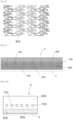
- a furnace 1 in which a glass sheet V moves along a roller conveyor V is shown. During its stay in the furnace, the glass sheet is brought to its softening temperature. The glass sheet is then led, still supported by the conveyor 3, to a forming device 4.
- This forming device 4 is where the softened glass sheet is manipulated to take its almost final shape.
- a pressing frame 5 is arranged under the plane defined by the roller conveyor 3.
- members not shown in the figures ensure precise positioning of said glass sheet, then its movement is stopped by the stopping of the rollers in the bending zone.
- the pressing frame 5 then passes through the bed of rollers 3 to lift the glass sheet.
- the pressing frame 5 has the shape that is desired to be given to the glass sheet V and fits the glass sheet.
- the pressing frame is designed so that it can pass through the roller bed 3.
- the pressing frame 5 having taken charge of the glass sheet V moves to press it against a bending form 6 positioned above the frame 5.
- the shaping of the glass sheet V is therefore done by pressing the glass sheet between the bending form and the pressing frame 5.
- the bending form 6 is associated with translation elements 70 in the form of mechanical jacks 71 as visible in
- the bending shape 6 is a surface, preferably solid, whose shape is adaptable, i.e. capable of allowing the production of glass sheets having different curvatures.
- This bending shape is, optionally, covered with an interlayer material of the knitted type composed of refractory fibers such as silica, metal or high-temperature resistant polymer such as Kevlar® fibers for example.
- This interlayer material has not been shown on the Figures 2 and 3 and following.
- the upper form 6 is a shaping tool according to the invention.
- Another application concerns the forming of a metal sheet in the forming device 4. This metal sheet is brought to a temperature at which it softens in order to then be shaped by the pressing frame and the bending form.
- the shaping tool is used in a process during which the substrate to be shaped is subjected to a rise in temperature.
- a process consists, for example, in producing a part made of composite material reinforced with fibers of any kind (metallic, carbon, glass or ceramic) from fiber sheets and a material to form the matrix of the product, for example of the resin type, applied in liquid form or from sheets.
- the shaping tool is positioned in the same way as in the [ Fig. 1 ] ; the shaping surface itself is then presented in the upper part of the device. The different types of materials are stacked in successive layers on the surface of the shaping tool.
- This entire stack conforms either naturally under its own weight, or by hand in order to firmly press the different layers of the stack against the forming surface, or using an upper counter-form in the form of a peripheral ring when the components of the stack have a natural rigidity that does not allow them to be shaped spontaneously under their own weight or manually.
- the entire stack can be introduced into a flexible bag in which it is possible to create a vacuum by pumping out the residual air.
- This bag is itself maintained in contact with the shaping tool.
- Said preparation then undergoes a step during which the matrix e which impregnates the fibers is hardened on the shaping tool, in order to form said composite material with the desired shape.
- This hardening can be carried out chemically by application of a hardening agent or by specific pressure or temperature conditions. This hardening can be exothermic, that is to say releasing heat.
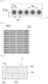
- a membrane 600 for a shaping tool according to the invention has dimensions in length and width of at least 100*100 mm and can go up to dimensions of 2000*3000 mm or greater and has a thickness of between 5 and 50 mm, preferably between 10 and 45 mm and more preferably between 15 and 40 mm.
- said shaping tool comprises thermalization means 700 as visible in [ Fig. 3 ].
- These thermalization means 700 comprise a plurality of conduits 702 in which a heat transfer fluid circulates. These conduits 702 extend in at least one of the directions (length, width) of the membrane, in its profile. Preferably, these conduits extend parallel to each other and parallel to the lower main face of the membrane 700 which is in contact with the glass sheet V to be formed.
- the thermalization means 700 comprise a first series of conduits 702 extending along the length of the membrane and a second series of conduits 702 extending along the width of the membrane.
- the conduits 702 are made of a flexible material allowing the conduits 702 to deform without breaking when the membrane 600 is shaped.
- a material that can, for example, be chosen is Teflon or polyethylene.
- These 702 conduits are arranged to allow for the best possible heat exchange.
- the distance criterion between the conduits and the lower face of the membrane is important because if the conduits 702 are too close to the lower face (in contact with the glass) then residual deformations of the lower surface of the membrane appear when it is mechanically stressed. These deformations appear in the form of regular lines causing slight hollow grooves on the surface of the membrane and which are likely to be transferred to the glass sheet during the forming operation.
- each conduit drains the heat into a virtual tube with a square base within the membrane whose side has the length of the distance d Wat approximately equal to 2 x E wat + D wat , where D wat is the diameter of the conduits containing the heat transfer fluid.
- the membrane 600 When forming a hot substrate, the membrane 600 requires cooling.
- the conduits 702 are used to transport a cooling liquid responsible for cooling said membrane 600.
- the thermalization circuit 700 allows the calories to be dissipated from the membrane
- the present invention is such that it cleverly allows the calories to be directed towards the thermalization means 700.
- the maximum heat is found at the surface of the membrane in contact with the hot substrate, while the conduits are arranged in the membrane.
- the invention advantageously allows the heat to be directed from the surface towards the thermalization means so that this heat can be dissipated.
- means for increasing the conductivity 800 are arranged in the membrane 600.
- the 802 particle proposal is variable so that the higher the particle rate, the greater the thermal conductivity.
- the particle rate can be up to 60% by volume.
- thermal conductivity values of around 0.2 W ⁇ m-1 ⁇ K-1 for the raw elastomer matrix we can easily move from thermal conductivity values of around 0.2 W ⁇ m-1 ⁇ K-1 for the raw elastomer matrix to a thermal conductivity value of 0.48 W ⁇ m-1 ⁇ K-1 with an aluminum particle loading rate of 40% by volume.
- the distribution of the particles 802 is made heterogeneous to make only one area of the membrane more thermally conductive.
- the chosen metal particles 802 have magnetic properties, i.e. they are capable of being attracted by a magnet. This possibility makes it possible, when molding the material forming the membrane 600 in which the particles 802 are mixed, to apply a magnetic force via magnets in order to attract the magnetic metal particles 802 to a defined area and therefore to control this distribution.
- This 804 insert is a textile that can come in different forms.
- the textile limits the possibilities of having free spaces between said fibers and said material constituting the membrane and therefore limits the degradation of thermal performance.
- This textile is preferably arranged between the lower surface of the upper form and the thermalization means 700.
- This arrangement makes it possible to conduct heat from the surface to the thermalization means 700 which evacuates it.
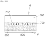
- This alternative is shown [ Fig.9 ]' where conductivity increasing means 800 are arranged in the lower part of the membrane 600.
- These conductivity increasing means 800 are composed of a stack of three inserts 804, in this case, three layers of impregnated metal knits filling the space between the lower surface of the membrane which comes into contact with the hot glass sheet V and the thermalization means 700 composed of a series of parallel conduits 702 in which a heat transfer fluid circulates.
- the interface between each layer of impregnated knit is represented by a dotted line 805.
- increasing the thermal conductivity of the membrane consists of integrating metallic or carbon fibers 806 into the material forming the membrane as visible at Figures 10a And 10b .
- These 806 metal fibers are in the form of strips or lamellae having a good form factor, i.e. allowing good conduction.
- These metal fibers have a length of approximately 0.5 to 10 mm for a width of between approximately 0.05 and 0.5 mm.
- the conductivity increasing means 800 may comprise several means such as for example a textile-type insert 804 and particles 802 or particles and fibers.
- the basic process consists of obtaining the material constituting the membrane and a mold having the shape of the membrane, then pouring/casting said material into the mold. Once the material has been poured, everything is left to rest so that the elastomer can crosslink.
- the mold is capable of allowing said means to be placed in the required position before the material constituting the membrane is poured into said mold.
- the thermalization means 700 are previously integrated into a layer of the material constituting the membrane.
- This alternative consists of providing a secondary mold in which the thermalization means 700 are placed and then casting the material constituting the membrane.
- the secondary mold has the same surface area as the main mold but with a lesser thickness. Once the material has been cast, it is left to rest so that it can crosslink. A “slice” of the material constituting the membrane is then obtained in which the thermalization means 700 are placed.
- these metal particles or fibers are incorporated into the elastomer material that makes up the membrane before it is poured into the mold.
- the elastomer material is stored in a container.
- the particles or fibers are then poured into the container and everything is mixed to achieve a homogeneous concentration.
- these metal particles or fibers are integrated into the elastomeric material constituting the membrane after it has been poured into the mold.
- two possibilities are possible: before the installation of the thermalization means 700 and then it is possible to mix these particles or fibers in the elastomer material in order to have a homogeneous distribution.
- the particles 802 or fibers 806 are integrated after the installation of the thermalization means 700 and they extend throughout the thickness by gravity.
- the particles or fibers are magnetic, to have magnetic means such as magnets around the mold in order to control the distribution of these particles or fibers.
- the method is modified to integrate a step of incorporating this textile.
- This textile is integrated at the time when the elastomeric material is poured into the mold and before the thermalization means 700 are put in place.
- the textile is placed in the mold. By gravity, it will position itself at the bottom of the mold, said bottom being the lower face or face in contact with the glass.
- a first iteration consists of pouring into the mold a quantity of elastomer such that it represents a thickness equal to 10% of the total thickness of the membrane. This quantity of elastomer material is then left to rest so that it can crosslink.
- the means for increasing the conductivity 800 in the form of particles can be mixed with the material constituting the membrane before or after pouring the latter.
- magnets can be placed around the mold to control the positioning of the textile.
- the membrane 600 has a thermal profile such that its temperature increases over time.
- the thermalization means 700 using a cooling liquid are then used to maintain said membrane at an operating temperature, this being dependent on the material constituting the membrane.
- the temperature profile has thus a transient profile in which the temperature evolves and a stable profile during which the membrane 600 is cooled and therefore the temperature is regulated.
- the conduits 702 are connected to a cooling circuit and a heating circuit.
- the transition from one to the other is done via valves controlled by a control unit.
- This control unit is also connected to means for measuring the temperature of the membrane.
- These measuring means comprise at least one sensor which may be a thermocouple or a thermal camera or an infrared sensor.
- the measuring means allow the control unit to switch from injecting a heating liquid into the thermalization means to a cooling liquid or vice versa.
Landscapes
- Chemical & Material Sciences (AREA)
- Engineering & Computer Science (AREA)
- Materials Engineering (AREA)
- Organic Chemistry (AREA)
- Moulds For Moulding Plastics Or The Like (AREA)
- Moulding By Coating Moulds (AREA)
- Laminated Bodies (AREA)
Claims (23)
- Formgebungswerkzeug, umfassend eine Membran (600) aus einem Polymermaterial, wobei die Membran eine Formgebungsoberfläche aufweist, dadurch gekennzeichnet, dass das Werkzeug in die Membran eingefügte Thermalisierungsmittel (700) umfasst
- Werkzeug nach Anspruch 1, wobei das Werkzeug ferner Mittel (800) zum Erhöhen der Wärmeleitfähigkeit der Membran umfasst.
- Werkzeug nach Anspruch 1, wobei die Thermalisierungsmittel (700) mindestens eine Leitung (702) umfassen, die durch die Membran entsprechend ihrem Profil verläuft und in der eine Wärmeträgerflüssigkeit zirkuliert.
- Werkzeug nach dem vorstehendem Anspruch, wobei die Thermalisierungsmittel (700) eine Reihe von Leitungen (702) umfassen, die durch die Membran entsprechend ihrem Profil verlaufen und in denen eine Wärmeträgerflüssigkeit zirkuliert, wobei sich diese Leitungen parallel zueinander erstrecken.
- Werkzeug nach dem vorstehendem Anspruch, wobei die Wärmeträgerflüssigkeit zweier benachbarter Leitungen (702) in entgegengesetzten Richtungen zirkuliert.
- Werkzeug nach einem der Ansprüche 3 bis 5, wobei es eine weitere Reihe von Leitungen umfasst, die sich in einer Richtung erstrecken, die orthogonal zu der Richtung ist, in der sich eine erste Reihe von Leitungen erstreckt.
- Werkzeug nach einem der vorstehenden Ansprüche, wobei die Mittel zum Erhöhen der Wärmeleitfähigkeit (800) der Membran Partikel (802) aus Metall oder auf Kohlenstoffbasis umfassen, die in das Polymermaterial eingebracht sind.
- Werkzeug nach einem der vorstehenden Ansprüche, wobei die Mittel zum Erhöhen der Wärmeleitfähigkeit (800) der Membran Fasern (806) aus Metall oder auf Kohlenstoffbasis umfassen.
- Werkzeug nach einem der Ansprüche 1 bis 6, wobei die Mittel zum Erhöhen der Wärmeleitfähigkeit (800) der Membran ein Textil (804) umfassen.
- Werkzeug nach dem vorstehendem Anspruch, wobei das Textil aus Metallfasern oder gesponnenen Fäden besteht oder ein Gewirk ist.
- Werkzeug nach einem der vorstehenden Ansprüche, wobei die Wärmeträgerflüssigkeit kühlend oder wärmend ist.
- Vorrichtung zum Biegen einer Glasscheibe, umfassend einen Pressrahmen (5), der so angeordnet ist, dass er sich an die Glasscheibe anpasst und sie gegen eine obere Form (6) presst, wobei die obere Form ein Formgebungswerkzeug nach einem der vorstehenden Ansprüche ist.
- Verfahren zur Herstellung einer Membran eines Formgebungswerkzeugs, das folgende Schritte umfasst:- Bereitstellen einer die Gestalt der herzustellenden Membran aufweisenden Form und des Polymermaterials, aus dem die Membran besteht:- Gießen des Materials in die Form;- Vernetzen des Materials;dadurch gekennzeichnet, dass das Verfahren einen Schritt des Einrichtens von Thermalisierungsmitteln (700) und mindestens einen Schritt des Einrichtens von Mitteln zum Erhöhen der Wärmeleitfähigkeit (800) umfasst.
- Verfahren nach dem vorstehendem Anspruch, wobei das Verfahren mehrere Schritte des Gießens des Materials in die Form und mehrere Schritte des Vernetzens des Materials umfasst, wobei auf jeden Schritt des Gießens des Materials in die Form ein Schritt des Vernetzens des Materials folgt.
- Verfahren nach einem der Ansprüche 13 oder 14, wobei der Schritt des Einrichtens der Thermalisierungsmittel darin besteht, die Thermalisierungsmittel bereitzustellen und in der Form zu platzieren, bevor das Material, aus dem die Membran besteht, gegossen wird.
- Verfahren nach einem der Ansprüche 13 bis 14, wobei der Schritt des Einrichtens der Thermalisierungsmittel (700) darin besteht, die Thermalisierungsmittel bereitzustellen und eine Zwischenform bereitzustellen, deren Oberfläche ähnlich der der herzustellenden Membran ist, jedoch eine geringere Dicke aufweist, die Thermalisierungsmittel (700) in der Zwischenform zu platzieren und einen Teil des Materials, aus dem die Membran besteht, in die Zwischenform zu gießen, wobei das Material sodann vernetzt wird, um ein Zwischenstück zu bilden, wobei das Zwischenstück während des Schritts des Gießens des Materials, aus dem die Membran besteht, in der Form der Membran platziert wird.
- Verfahren nach einem der Ansprüche 13 bis 16, wobei der Schritt des Einrichtens der Mittel zum Erhöhen der Wärmeleitfähigkeit (800) darin besteht, die Mittel zum Erhöhen der Wärmeleitfähigkeit in Form von Partikeln (802) oder Fasern (806) aus Metall oder Kunststoff bereitzustellen und diese mit dem Material zu vermischen, aus dem die Membran besteht, bevor dieses Material gegossen wird.
- Verfahren nach einem der Ansprüche 13 bis 16, wobei der Schritt des Einrichtens der Mittel zum Erhöhen der Wärmeleitfähigkeit darin besteht, die Mittel zum Erhöhen der Wärmeleitfähigkeit in Form von Partikeln oder Fasern aus Metall oder Kunststoff bereitzustellen und diese nach dem Gießen des Materials, aus dem die Membran besteht, mit dem Material, aus dem die Membran besteht, zu vermischen.
- Verfahren nach einem der Ansprüche 13 bis 16, wobei der Schritt des Einrichtens der Mittel zum Erhöhen der Wärmeleitfähigkeit darin besteht, die Mittel zum Erhöhen der Wärmeleitfähigkeit in Form eines Textils bereitzustellen und diese während des Gießens des Materials, aus dem die Membran besteht, in der Form zu platzieren.
- Verfahren nach einem der Ansprüche 13 bis 16, wobei der Schritt des Einrichtens der Mittel zum Erhöhen der Wärmeleitfähigkeit in Form eines Textils darin besteht, ein Textil bereitzustellen und eine Zwischenform bereitzustellen, deren Oberfläche ähnlich der der herzustellenden Membran ist, jedoch eine geringere Dicke aufweist, das Textil dort hinein zu platzieren und einen Teil des Materials, aus dem die Membran besteht, in die Zwischenform zu gießen, wobei das Material dann vernetzt wird, um ein Zwischenstück zu bilden,
wobei dieses Zwischenstück während des Schritts des Gießens des Materials, aus dem die Membran besteht, in der Membranform platziert wird. - Verfahren nach einem der Ansprüche 13 bis 20, wobei Mittel zum Erhöhen der Wärmeleitfähigkeit magnetisch sind und wobei bei mindestens einem Schritt des Einrichtens von Mitteln zum Erhöhen der Wärmeleitfähigkeit Magnete zu deren Positionierung verwendet werden.
- Verfahren nach einem der Ansprüche 13 bis 21, wobei das Verfahren derart ist, dass es vor den Schritten des Einrichtens von Thermalisierungsmitteln (700) und des Einrichtens von Mitteln zum Erhöhen der Wärmeleitfähigkeit mindestens einen Schritt des Gießens eines Teils des Materials, aus dem die Membran besteht, und einen Schritt des Vernetzens dieses Materials umfasst.
- Verfahren zum Thermalisieren eines Werkzeugs nach einem der Ansprüche 1 bis 11, wobei das Verfahren im kontinuierlichen Messen der Temperatur des Werkzeugs durch Temperaturmessmittel und Vergleichen der gemessenen Temperatur mit einer definierten Arbeitstemperatur besteht, wobei, wenn die gemessene Temperatur unter der definierten Arbeitstemperatur liegt, die Thermalisierungsmittel das Werkzeug erwärmen, und wenn die gemessene Temperatur über der definierten Arbeitstemperatur liegt, die Thermalisierungsmittel das Werkzeug abkühlen.
Applications Claiming Priority (2)
| Application Number | Priority Date | Filing Date | Title |
|---|---|---|---|
| FR2106247A FR3123911B1 (fr) | 2021-06-14 | 2021-06-14 | Outil de conformation d’un substrat chaud |
| PCT/FR2022/051125 WO2022263759A1 (fr) | 2021-06-14 | 2022-06-13 | Outil de conformation d'un substrat chaud |
Publications (3)
| Publication Number | Publication Date |
|---|---|
| EP4355698A1 EP4355698A1 (de) | 2024-04-24 |
| EP4355698B1 true EP4355698B1 (de) | 2025-04-09 |
| EP4355698B8 EP4355698B8 (de) | 2025-05-21 |
Family
ID=77710939
Family Applications (1)
| Application Number | Title | Priority Date | Filing Date |
|---|---|---|---|
| EP22735219.2A Active EP4355698B8 (de) | 2021-06-14 | 2022-06-13 | Werkzeug zum formen eines heissen substrats |
Country Status (6)
| Country | Link |
|---|---|
| US (1) | US20240254031A1 (de) |
| EP (1) | EP4355698B8 (de) |
| CN (1) | CN115943127B (de) |
| FR (1) | FR3123911B1 (de) |
| PL (1) | PL4355698T3 (de) |
| WO (1) | WO2022263759A1 (de) |
Citations (2)
| Publication number | Priority date | Publication date | Assignee | Title |
|---|---|---|---|---|
| WO2003064337A1 (fr) | 2002-01-28 | 2003-08-07 | Asahi Glass Company, Limited | Dispositif et monture pour plaque de verre |
| US20050211870A1 (en) | 2004-03-12 | 2005-09-29 | Browne Alan L | Active and reconfigurable tools |
Family Cites Families (8)
| Publication number | Priority date | Publication date | Assignee | Title |
|---|---|---|---|---|
| US5938810A (en) * | 1996-10-23 | 1999-08-17 | Donnelly Corporation | Apparatus for tempering and bending glass |
| AU764889B2 (en) * | 1999-04-09 | 2003-09-04 | N.V. Bekaert S.A. | Heat resistant covering material |
| DE10335453B4 (de) * | 2003-08-02 | 2007-03-01 | Schott Ag | Verfahren zum Biegen von Flachglas und zugehörige Biegevorrichtung |
| WO2010064083A1 (en) * | 2008-07-31 | 2010-06-10 | Mei S.R.L. | Procedure and equipment for making glass frames and glass frame obtained therewith |
| EP2505327B1 (de) * | 2011-03-29 | 2013-06-19 | Techni-Modul Engineering | Herstellungsverfahren eines Formgusswerkzeugs, das für den Formguss eines Verbundwerkstücks bestimmt ist |
| FR2994121B1 (fr) * | 2012-08-03 | 2015-02-06 | Techni Modul Engineering | Procede de fabrication d’un outillage de moulage destine au moulage d’une piece en materiau composite |
| BR112017025428B1 (pt) * | 2015-05-27 | 2022-11-16 | Pilkington Group Limited | Método para moldagem de uma chapa de vidro, e linha de moldagem de vidro para moldar uma chapa de vidro |
| PL3408233T3 (pl) * | 2016-01-28 | 2020-03-31 | Saint-Gobain Glass France | Wspomagany nadciśnieniem sposób gięcia szkła i odpowiednie do tego urządzenie |
-
2021
- 2021-06-14 FR FR2106247A patent/FR3123911B1/fr active Active
-
2022
- 2022-06-13 US US18/566,438 patent/US20240254031A1/en active Pending
- 2022-06-13 PL PL22735219.2T patent/PL4355698T3/pl unknown
- 2022-06-13 WO PCT/FR2022/051125 patent/WO2022263759A1/fr not_active Ceased
- 2022-06-13 EP EP22735219.2A patent/EP4355698B8/de active Active
- 2022-06-13 CN CN202280004693.4A patent/CN115943127B/zh active Active
Patent Citations (2)
| Publication number | Priority date | Publication date | Assignee | Title |
|---|---|---|---|---|
| WO2003064337A1 (fr) | 2002-01-28 | 2003-08-07 | Asahi Glass Company, Limited | Dispositif et monture pour plaque de verre |
| US20050211870A1 (en) | 2004-03-12 | 2005-09-29 | Browne Alan L | Active and reconfigurable tools |
Also Published As
| Publication number | Publication date |
|---|---|
| EP4355698A1 (de) | 2024-04-24 |
| WO2022263759A1 (fr) | 2022-12-22 |
| CN115943127A (zh) | 2023-04-07 |
| FR3123911A1 (fr) | 2022-12-16 |
| EP4355698B8 (de) | 2025-05-21 |
| FR3123911B1 (fr) | 2023-05-19 |
| US20240254031A1 (en) | 2024-08-01 |
| PL4355698T3 (pl) | 2025-06-16 |
| CN115943127B (zh) | 2026-01-02 |
Similar Documents
| Publication | Publication Date | Title |
|---|---|---|
| EP3302943B1 (de) | Verfahren zum imprägnieren einer hohlen fasrigen textur | |
| EP0557140B1 (de) | Verfahren zum Aufbauen eines Faserverbundwerkstoffes mit Glasmatrix mittels Wickeln und Erwärmung und Vorrichtung zur Durchführung des Verfahrens | |
| EP3827118B1 (de) | Fasertextur für ein gehäuse aus verbundmaterial mit verbesserter scherfestigkeit | |
| FR3066429A1 (fr) | Installation et procede pour la fabrication d'une preforme fibreuse par enroulement d'une texture fibreuse en forme de bande | |
| EP4355698B1 (de) | Werkzeug zum formen eines heissen substrats | |
| WO2020234313A1 (fr) | Dispositif et procédé de fabrication d'une pièce en matériau composite | |
| WO2011098291A1 (fr) | Dispositif multicouche pour un moule a chauffage endogene et procede de fabrication dudit dispositif | |
| EP3843982A1 (de) | Verfahren zum formen einer faserigen vorform durch verdichtung zur herstellung eines verbundstoffmaterialteils | |
| EP3529028B1 (de) | Verfahren und vorrichtung zum verfestigen einer textilen vorform und umspritzen | |
| WO2024189276A1 (fr) | Fabrication de pièces en matériau composite par infiltration chimique modulée puis densification dune préforme fibreuse consolidée | |
| WO2017046538A1 (fr) | Pièce en matériau composite | |
| EP3711934B1 (de) | Verbundmaterial und herstellungsverfahren eines solchen verbundmaterials | |
| EP3089855A1 (de) | Verfahren zur injektion einer behälterwand mit einer lokalisierten verstärkungsschicht | |
| WO2016139359A1 (fr) | Moule en bois avec trame chauffante | |
| EP3339010A1 (de) | Heizpresse, pressanordnung, einstellverfahren und einsatzbereiche einer solchen heizpresse | |
| FR3055243A1 (fr) | Fabrication d'un composite moule renforce par des fibres par infusion sequentielle | |
| FR3126915A1 (fr) | Procédé de fabrication d’une pièce en matériau composite | |
| WO2025021634A1 (fr) | Moule de cuisson pour pneumatique | |
| FR3141378A1 (fr) | Procede de fabrication d’une piece en materiau composite a matrice thermodurcissable renforcee par des fibres longues discontinues | |
| FR2870860A1 (fr) | Complexe utilisable comme armature dans une piece obtenue par injection sous vide | |
| FR3154033A1 (fr) | Aube en matériau composite comprenant des fibres d’amortissement | |
| FR3137324A1 (fr) | Assemblage d’une pièce métallique et d’une pièce en matériau composite | |
| FR3094609A1 (fr) | TApis chauffant dÉformable et conformable | |
| FR2738237A1 (fr) | Procede et dispositif de fabrication d'une barre a section droite rectangulaire, en un materiau presentant un gradient de composition perpendiculairement a deux faces longitudinales opposees de la barre | |
| WO2021013769A1 (fr) | Procédé de fabrication de préformes pour matériaux composites |
Legal Events
| Date | Code | Title | Description |
|---|---|---|---|
| STAA | Information on the status of an ep patent application or granted ep patent |
Free format text: STATUS: UNKNOWN |
|
| STAA | Information on the status of an ep patent application or granted ep patent |
Free format text: STATUS: THE INTERNATIONAL PUBLICATION HAS BEEN MADE |
|
| PUAI | Public reference made under article 153(3) epc to a published international application that has entered the european phase |
Free format text: ORIGINAL CODE: 0009012 |
|
| STAA | Information on the status of an ep patent application or granted ep patent |
Free format text: STATUS: REQUEST FOR EXAMINATION WAS MADE |
|
| 17P | Request for examination filed |
Effective date: 20240115 |
|
| AK | Designated contracting states |
Kind code of ref document: A1 Designated state(s): AL AT BE BG CH CY CZ DE DK EE ES FI FR GB GR HR HU IE IS IT LI LT LU LV MC MK MT NL NO PL PT RO RS SE SI SK SM TR |
|
| DAV | Request for validation of the european patent (deleted) | ||
| DAX | Request for extension of the european patent (deleted) | ||
| GRAP | Despatch of communication of intention to grant a patent |
Free format text: ORIGINAL CODE: EPIDOSNIGR1 |
|
| STAA | Information on the status of an ep patent application or granted ep patent |
Free format text: STATUS: GRANT OF PATENT IS INTENDED |
|
| INTG | Intention to grant announced |
Effective date: 20241108 |
|
| GRAS | Grant fee paid |
Free format text: ORIGINAL CODE: EPIDOSNIGR3 |
|
| GRAA | (expected) grant |
Free format text: ORIGINAL CODE: 0009210 |
|
| STAA | Information on the status of an ep patent application or granted ep patent |
Free format text: STATUS: THE PATENT HAS BEEN GRANTED |
|
| AK | Designated contracting states |
Kind code of ref document: B1 Designated state(s): AL AT BE BG CH CY CZ DE DK EE ES FI FR GB GR HR HU IE IS IT LI LT LU LV MC MK MT NL NO PL PT RO RS SE SI SK SM TR |
|
| REG | Reference to a national code |
Ref country code: GB Ref legal event code: FG4D Free format text: NOT ENGLISH |
|
| REG | Reference to a national code |
Ref country code: CH Ref legal event code: EP |
|
| REG | Reference to a national code |
Ref country code: DE Ref legal event code: R081 Ref document number: 602022012991 Country of ref document: DE Owner name: SAINT-GOBAIN SEKURIT FRANCE, FR Free format text: FORMER OWNER: SAINT-GOBAIN GLASS FRANCE, COURBEVOIE, FR |
|
| REG | Reference to a national code |
Ref country code: CH Ref legal event code: PK Free format text: RECTIFICATION B8 Ref country code: DE Ref legal event code: R096 Ref document number: 602022012991 Country of ref document: DE |
|
| REG | Reference to a national code |
Ref country code: IE Ref legal event code: FG4D Free format text: LANGUAGE OF EP DOCUMENT: FRENCH |
|
| RAP2 | Party data changed (patent owner data changed or rights of a patent transferred) |
Owner name: SAINT-GOBAIN SEKURIT FRANCE |
|
| PGFP | Annual fee paid to national office [announced via postgrant information from national office to epo] |
Ref country code: PL Payment date: 20250504 Year of fee payment: 4 Ref country code: DE Payment date: 20250429 Year of fee payment: 4 |
|
| PGFP | Annual fee paid to national office [announced via postgrant information from national office to epo] |
Ref country code: FR Payment date: 20250508 Year of fee payment: 4 |
|
| PGFP | Annual fee paid to national office [announced via postgrant information from national office to epo] |
Ref country code: AT Payment date: 20250721 Year of fee payment: 4 |
|
| PGFP | Annual fee paid to national office [announced via postgrant information from national office to epo] |
Ref country code: TR Payment date: 20250612 Year of fee payment: 4 |
|
| REG | Reference to a national code |
Ref country code: NL Ref legal event code: MP Effective date: 20250409 |
|
| PG25 | Lapsed in a contracting state [announced via postgrant information from national office to epo] |
Ref country code: NL Free format text: LAPSE BECAUSE OF FAILURE TO SUBMIT A TRANSLATION OF THE DESCRIPTION OR TO PAY THE FEE WITHIN THE PRESCRIBED TIME-LIMIT Effective date: 20250409 |
|
| REG | Reference to a national code |
Ref country code: AT Ref legal event code: MK05 Ref document number: 1783433 Country of ref document: AT Kind code of ref document: T Effective date: 20250409 |
|
| PG25 | Lapsed in a contracting state [announced via postgrant information from national office to epo] |
Ref country code: PT Free format text: LAPSE BECAUSE OF FAILURE TO SUBMIT A TRANSLATION OF THE DESCRIPTION OR TO PAY THE FEE WITHIN THE PRESCRIBED TIME-LIMIT Effective date: 20250811 Ref country code: FI Free format text: LAPSE BECAUSE OF FAILURE TO SUBMIT A TRANSLATION OF THE DESCRIPTION OR TO PAY THE FEE WITHIN THE PRESCRIBED TIME-LIMIT Effective date: 20250409 Ref country code: ES Free format text: LAPSE BECAUSE OF FAILURE TO SUBMIT A TRANSLATION OF THE DESCRIPTION OR TO PAY THE FEE WITHIN THE PRESCRIBED TIME-LIMIT Effective date: 20250409 |
|
| REG | Reference to a national code |
Ref country code: LT Ref legal event code: MG9D |
|
| PG25 | Lapsed in a contracting state [announced via postgrant information from national office to epo] |
Ref country code: NO Free format text: LAPSE BECAUSE OF FAILURE TO SUBMIT A TRANSLATION OF THE DESCRIPTION OR TO PAY THE FEE WITHIN THE PRESCRIBED TIME-LIMIT Effective date: 20250709 Ref country code: GR Free format text: LAPSE BECAUSE OF FAILURE TO SUBMIT A TRANSLATION OF THE DESCRIPTION OR TO PAY THE FEE WITHIN THE PRESCRIBED TIME-LIMIT Effective date: 20250710 |
|
| PGFP | Annual fee paid to national office [announced via postgrant information from national office to epo] |
Ref country code: IT Payment date: 20250630 Year of fee payment: 4 |
|
| PG25 | Lapsed in a contracting state [announced via postgrant information from national office to epo] |
Ref country code: BG Free format text: LAPSE BECAUSE OF FAILURE TO SUBMIT A TRANSLATION OF THE DESCRIPTION OR TO PAY THE FEE WITHIN THE PRESCRIBED TIME-LIMIT Effective date: 20250409 |
|
| PG25 | Lapsed in a contracting state [announced via postgrant information from national office to epo] |
Ref country code: AT Free format text: LAPSE BECAUSE OF FAILURE TO SUBMIT A TRANSLATION OF THE DESCRIPTION OR TO PAY THE FEE WITHIN THE PRESCRIBED TIME-LIMIT Effective date: 20250409 Ref country code: HR Free format text: LAPSE BECAUSE OF FAILURE TO SUBMIT A TRANSLATION OF THE DESCRIPTION OR TO PAY THE FEE WITHIN THE PRESCRIBED TIME-LIMIT Effective date: 20250409 |
|
| PG25 | Lapsed in a contracting state [announced via postgrant information from national office to epo] |
Ref country code: RS Free format text: LAPSE BECAUSE OF FAILURE TO SUBMIT A TRANSLATION OF THE DESCRIPTION OR TO PAY THE FEE WITHIN THE PRESCRIBED TIME-LIMIT Effective date: 20250709 |
|
| PG25 | Lapsed in a contracting state [announced via postgrant information from national office to epo] |
Ref country code: IS Free format text: LAPSE BECAUSE OF FAILURE TO SUBMIT A TRANSLATION OF THE DESCRIPTION OR TO PAY THE FEE WITHIN THE PRESCRIBED TIME-LIMIT Effective date: 20250809 |
|
| PG25 | Lapsed in a contracting state [announced via postgrant information from national office to epo] |
Ref country code: LV Free format text: LAPSE BECAUSE OF FAILURE TO SUBMIT A TRANSLATION OF THE DESCRIPTION OR TO PAY THE FEE WITHIN THE PRESCRIBED TIME-LIMIT Effective date: 20250409 |
|
| REG | Reference to a national code |
Ref country code: DE Ref legal event code: R026 Ref document number: 602022012991 Country of ref document: DE |
|
| PG25 | Lapsed in a contracting state [announced via postgrant information from national office to epo] |
Ref country code: SM Free format text: LAPSE BECAUSE OF FAILURE TO SUBMIT A TRANSLATION OF THE DESCRIPTION OR TO PAY THE FEE WITHIN THE PRESCRIBED TIME-LIMIT Effective date: 20250409 Ref country code: DK Free format text: LAPSE BECAUSE OF FAILURE TO SUBMIT A TRANSLATION OF THE DESCRIPTION OR TO PAY THE FEE WITHIN THE PRESCRIBED TIME-LIMIT Effective date: 20250409 |
|
| PLBI | Opposition filed |
Free format text: ORIGINAL CODE: 0009260 |
|
| PG25 | Lapsed in a contracting state [announced via postgrant information from national office to epo] |
Ref country code: CZ Free format text: LAPSE BECAUSE OF FAILURE TO SUBMIT A TRANSLATION OF THE DESCRIPTION OR TO PAY THE FEE WITHIN THE PRESCRIBED TIME-LIMIT Effective date: 20250409 |
|
| REG | Reference to a national code |
Ref country code: CH Ref legal event code: L10 Free format text: ST27 STATUS EVENT CODE: U-0-0-L10-L00 (AS PROVIDED BY THE NATIONAL OFFICE) Effective date: 20260121 |
|
| PLAX | Notice of opposition and request to file observation + time limit sent |
Free format text: ORIGINAL CODE: EPIDOSNOBS2 |
|
| PG25 | Lapsed in a contracting state [announced via postgrant information from national office to epo] |
Ref country code: SK Free format text: LAPSE BECAUSE OF FAILURE TO SUBMIT A TRANSLATION OF THE DESCRIPTION OR TO PAY THE FEE WITHIN THE PRESCRIBED TIME-LIMIT Effective date: 20250409 |
|
| REG | Reference to a national code |
Ref country code: CH Ref legal event code: H13 Free format text: ST27 STATUS EVENT CODE: U-0-0-H10-H13 (AS PROVIDED BY THE NATIONAL OFFICE) Effective date: 20260127 |
|
| PLAF | Information modified related to communication of a notice of opposition and request to file observations + time limit |
Free format text: ORIGINAL CODE: EPIDOSCOBS2 |