EP4355283B1 - A knee movement assistive device - Google Patents
A knee movement assistive device Download PDFInfo
- Publication number
- EP4355283B1 EP4355283B1 EP22728980.8A EP22728980A EP4355283B1 EP 4355283 B1 EP4355283 B1 EP 4355283B1 EP 22728980 A EP22728980 A EP 22728980A EP 4355283 B1 EP4355283 B1 EP 4355283B1
- Authority
- EP
- European Patent Office
- Prior art keywords
- gear
- driver
- configuration
- garment
- assistive device
- Prior art date
- Legal status (The legal status is an assumption and is not a legal conclusion. Google has not performed a legal analysis and makes no representation as to the accuracy of the status listed.)
- Active
Links
Images







Classifications
-
- A—HUMAN NECESSITIES
- A61—MEDICAL OR VETERINARY SCIENCE; HYGIENE
- A61H—PHYSICAL THERAPY APPARATUS, e.g. DEVICES FOR LOCATING OR STIMULATING REFLEX POINTS IN THE BODY; ARTIFICIAL RESPIRATION; MASSAGE; BATHING DEVICES FOR SPECIAL THERAPEUTIC OR HYGIENIC PURPOSES OR SPECIFIC PARTS OF THE BODY
- A61H3/00—Appliances for aiding patients or disabled persons to walk about
-
- A—HUMAN NECESSITIES
- A61—MEDICAL OR VETERINARY SCIENCE; HYGIENE
- A61H—PHYSICAL THERAPY APPARATUS, e.g. DEVICES FOR LOCATING OR STIMULATING REFLEX POINTS IN THE BODY; ARTIFICIAL RESPIRATION; MASSAGE; BATHING DEVICES FOR SPECIAL THERAPEUTIC OR HYGIENIC PURPOSES OR SPECIFIC PARTS OF THE BODY
- A61H1/00—Apparatus for passive exercising; Vibrating apparatus; Chiropractic devices, e.g. body impacting devices, external devices for briefly extending or aligning unbroken bones
- A61H1/02—Stretching or bending or torsioning apparatus for exercising
- A61H1/0237—Stretching or bending or torsioning apparatus for exercising for the lower limbs
- A61H1/024—Knee
-
- A—HUMAN NECESSITIES
- A61—MEDICAL OR VETERINARY SCIENCE; HYGIENE
- A61H—PHYSICAL THERAPY APPARATUS, e.g. DEVICES FOR LOCATING OR STIMULATING REFLEX POINTS IN THE BODY; ARTIFICIAL RESPIRATION; MASSAGE; BATHING DEVICES FOR SPECIAL THERAPEUTIC OR HYGIENIC PURPOSES OR SPECIFIC PARTS OF THE BODY
- A61H1/00—Apparatus for passive exercising; Vibrating apparatus; Chiropractic devices, e.g. body impacting devices, external devices for briefly extending or aligning unbroken bones
- A61H1/02—Stretching or bending or torsioning apparatus for exercising
- A61H1/0237—Stretching or bending or torsioning apparatus for exercising for the lower limbs
- A61H1/0255—Both knee and hip of a patient, e.g. in supine or sitting position, the feet being moved together in a plane substantially parallel to the body-symmetrical plane
-
- A—HUMAN NECESSITIES
- A61—MEDICAL OR VETERINARY SCIENCE; HYGIENE
- A61H—PHYSICAL THERAPY APPARATUS, e.g. DEVICES FOR LOCATING OR STIMULATING REFLEX POINTS IN THE BODY; ARTIFICIAL RESPIRATION; MASSAGE; BATHING DEVICES FOR SPECIAL THERAPEUTIC OR HYGIENIC PURPOSES OR SPECIFIC PARTS OF THE BODY
- A61H3/00—Appliances for aiding patients or disabled persons to walk about
- A61H2003/007—Appliances for aiding patients or disabled persons to walk about secured to the patient, e.g. with belts
-
- A—HUMAN NECESSITIES
- A61—MEDICAL OR VETERINARY SCIENCE; HYGIENE
- A61H—PHYSICAL THERAPY APPARATUS, e.g. DEVICES FOR LOCATING OR STIMULATING REFLEX POINTS IN THE BODY; ARTIFICIAL RESPIRATION; MASSAGE; BATHING DEVICES FOR SPECIAL THERAPEUTIC OR HYGIENIC PURPOSES OR SPECIFIC PARTS OF THE BODY
- A61H2201/00—Characteristics of apparatus not provided for in the preceding codes
- A61H2201/12—Driving means
- A61H2201/1207—Driving means with electric or magnetic drive
- A61H2201/1215—Rotary drive
-
- A—HUMAN NECESSITIES
- A61—MEDICAL OR VETERINARY SCIENCE; HYGIENE
- A61H—PHYSICAL THERAPY APPARATUS, e.g. DEVICES FOR LOCATING OR STIMULATING REFLEX POINTS IN THE BODY; ARTIFICIAL RESPIRATION; MASSAGE; BATHING DEVICES FOR SPECIAL THERAPEUTIC OR HYGIENIC PURPOSES OR SPECIFIC PARTS OF THE BODY
- A61H2201/00—Characteristics of apparatus not provided for in the preceding codes
- A61H2201/12—Driving means
- A61H2201/1253—Driving means driven by a human being, e.g. hand driven
- A61H2201/1261—Driving means driven by a human being, e.g. hand driven combined with active exercising of the patient
-
- A—HUMAN NECESSITIES
- A61—MEDICAL OR VETERINARY SCIENCE; HYGIENE
- A61H—PHYSICAL THERAPY APPARATUS, e.g. DEVICES FOR LOCATING OR STIMULATING REFLEX POINTS IN THE BODY; ARTIFICIAL RESPIRATION; MASSAGE; BATHING DEVICES FOR SPECIAL THERAPEUTIC OR HYGIENIC PURPOSES OR SPECIFIC PARTS OF THE BODY
- A61H2201/00—Characteristics of apparatus not provided for in the preceding codes
- A61H2201/16—Physical interface with patient
- A61H2201/1602—Physical interface with patient kind of interface, e.g. head rest, knee support or lumbar support
- A61H2201/1628—Pelvis
-
- A—HUMAN NECESSITIES
- A61—MEDICAL OR VETERINARY SCIENCE; HYGIENE
- A61H—PHYSICAL THERAPY APPARATUS, e.g. DEVICES FOR LOCATING OR STIMULATING REFLEX POINTS IN THE BODY; ARTIFICIAL RESPIRATION; MASSAGE; BATHING DEVICES FOR SPECIAL THERAPEUTIC OR HYGIENIC PURPOSES OR SPECIFIC PARTS OF THE BODY
- A61H2201/00—Characteristics of apparatus not provided for in the preceding codes
- A61H2201/16—Physical interface with patient
- A61H2201/1602—Physical interface with patient kind of interface, e.g. head rest, knee support or lumbar support
- A61H2201/1635—Hand or arm, e.g. handle
- A61H2201/1638—Holding means therefor
-
- A—HUMAN NECESSITIES
- A61—MEDICAL OR VETERINARY SCIENCE; HYGIENE
- A61H—PHYSICAL THERAPY APPARATUS, e.g. DEVICES FOR LOCATING OR STIMULATING REFLEX POINTS IN THE BODY; ARTIFICIAL RESPIRATION; MASSAGE; BATHING DEVICES FOR SPECIAL THERAPEUTIC OR HYGIENIC PURPOSES OR SPECIFIC PARTS OF THE BODY
- A61H2201/00—Characteristics of apparatus not provided for in the preceding codes
- A61H2201/16—Physical interface with patient
- A61H2201/1602—Physical interface with patient kind of interface, e.g. head rest, knee support or lumbar support
- A61H2201/164—Feet or leg, e.g. pedal
- A61H2201/1642—Holding means therefor
-
- A—HUMAN NECESSITIES
- A61—MEDICAL OR VETERINARY SCIENCE; HYGIENE
- A61H—PHYSICAL THERAPY APPARATUS, e.g. DEVICES FOR LOCATING OR STIMULATING REFLEX POINTS IN THE BODY; ARTIFICIAL RESPIRATION; MASSAGE; BATHING DEVICES FOR SPECIAL THERAPEUTIC OR HYGIENIC PURPOSES OR SPECIFIC PARTS OF THE BODY
- A61H2201/00—Characteristics of apparatus not provided for in the preceding codes
- A61H2201/16—Physical interface with patient
- A61H2201/1602—Physical interface with patient kind of interface, e.g. head rest, knee support or lumbar support
- A61H2201/165—Wearable interfaces
-
- A—HUMAN NECESSITIES
- A61—MEDICAL OR VETERINARY SCIENCE; HYGIENE
- A61H—PHYSICAL THERAPY APPARATUS, e.g. DEVICES FOR LOCATING OR STIMULATING REFLEX POINTS IN THE BODY; ARTIFICIAL RESPIRATION; MASSAGE; BATHING DEVICES FOR SPECIAL THERAPEUTIC OR HYGIENIC PURPOSES OR SPECIFIC PARTS OF THE BODY
- A61H2201/00—Characteristics of apparatus not provided for in the preceding codes
- A61H2201/50—Control means thereof
- A61H2201/5007—Control means thereof computer controlled
-
- A—HUMAN NECESSITIES
- A61—MEDICAL OR VETERINARY SCIENCE; HYGIENE
- A61H—PHYSICAL THERAPY APPARATUS, e.g. DEVICES FOR LOCATING OR STIMULATING REFLEX POINTS IN THE BODY; ARTIFICIAL RESPIRATION; MASSAGE; BATHING DEVICES FOR SPECIAL THERAPEUTIC OR HYGIENIC PURPOSES OR SPECIFIC PARTS OF THE BODY
- A61H2203/00—Additional characteristics concerning the patient
- A61H2203/04—Position of the patient
- A61H2203/0406—Standing on the feet
-
- A—HUMAN NECESSITIES
- A61—MEDICAL OR VETERINARY SCIENCE; HYGIENE
- A61H—PHYSICAL THERAPY APPARATUS, e.g. DEVICES FOR LOCATING OR STIMULATING REFLEX POINTS IN THE BODY; ARTIFICIAL RESPIRATION; MASSAGE; BATHING DEVICES FOR SPECIAL THERAPEUTIC OR HYGIENIC PURPOSES OR SPECIFIC PARTS OF THE BODY
- A61H2203/00—Additional characteristics concerning the patient
- A61H2203/04—Position of the patient
- A61H2203/0412—Kneeling
Definitions
- the present invention is related to a knee movement assistive device.
- Said assistive device is particularly useful in assisting the knee movement of a user undergoing rehabilitation therapy.
- said assistive device is particularly useful in assisting a user performing a squat.
- XP081027759 discloses a knee exoskeleton comprising a waist garment attachable to a user waist, a calf garment attachable to a user calf, a first gear, a second gear, and an actuator attached to the waist garment and comprising a driver, said driver being configured to switch between an active state, wherein the driver generates a rotational force, and an idle state, wherein the driver generates a null force.
- the knee movement assistive device described does not cause high discomfort in the user wearing said assistive device, reducing the risk of not using the assistive device.
- the locking means 6 are configured to switch between a locking configuration and a releasing configuration.
- the second gear 43 is prevented to rotate around the second rotation center.
- the rotation of the first gear 42 makes the second gear 43 rotate around the second rotation center so that the rotational force generated by the driver 41 is transformed in the tension force and can be transmitted to the calf garment 3 through the transmission cable 5.
- the rotation of the second gear 43 pulls the transmission cable 5 or release the pull action on the transmission cable 5.
- the rotational force of the driver 41 is transformed in a first tension force acting as pull force or in a second tension force acting as a releasing force.
- the second tension force progressively release the first tension force, namely release the pull action transmitted to the calf garment 3.
- the second tension force is opposite to the first tension force.
- the locking means 6 are configured to switch from the locking configuration to the releasing configuration due to the rotation of the first gear 42 when the driver 41 is in the active state. Therefore, when the driver 41 is in the active state, the tension force can be transmitted to the calf garment 3 to assist the user knee movement.
- the locking means 6 are configured to automatically switch from the releasing configuration to the locking configuration when the driver 41 is switched to the idle state. Therefore, when the driver 41 is switched to the idle state, being the locking means 6 in the locking configuration, the tension force generated from the rotational force of the driver 41 is still transmitted to the calf garment 3, without needing to maintain the driver 41 in the active state. In other words, after the desired tension force has been transmitted to the calf garment 3, the driver 41 can be switched to the idle state letting the desired tension force still act on the calf garment 3.
- the driver 41 can be switched to the idle state continuing assisting the user knee movement and reducing, therefore, the overall energy needed to assist the user knee movement with the assistive device 1.
- the second gear 43 has a plurality of second teeth 432 arranged on the second perimetral wall 431.
- the second teeth 432 are equally spaced apart from each other along the second circumferential direction. The rotation of second gear 43 around the second rotation center making the second teeth 432 move along the second circumferential direction.
- the second gear 43 has twenty-five second teeth 432.
- the first gear 42 is configured to clockwise and anticlockwise rotate due to the rotational force generated by the driver 41. It should be noted that, due to the progressively engagement of each first tooth 422 with a respective second tooth 432, the clockwise rotation of the first gear 42 is transformed in an anticlockwise rotation of the second gear 43, while the anticlockwise rotation of the first gear 42 is transformed in a clockwise rotation of the second gear 43. Namely, the rotation direction of the first gear 42 is preferably opposite to the rotation direction of the second gear 43.
- each couple of second teeth 432 is spaced apart by a respective separation distance along the second circumferential direction. Said separation distance is greater than the thickness of each first tooth 422 along the first circumferential direction.
- At least one first tooth 422 is interposed between a couple of second teeth 432 and is spaced apart from each of said second teeth 432 in the locking configuration of the locking means 6.
- the rotational force of the driver 41 makes said first tooth 422 engaging one of said second teeth 432.
- the rotation of the first gear 42 switches the locking means 6 from the locking configuration to the releasing configuration. Namely, the locking means 6 are switched from the locking configuration to the releasing configuration before the first gear 42 makes the second gear 43 to rotate around the second rotation center. In this way, no rotation of the second gear 43 occurs when the locking means 6 are in the locking configuration.
- the locking means 6 comprises a stopper 61 having a first engagement portion 611.
- the first engagement portion 611 has a tip shape.
- the stopper 61 is configured to assume in the locking configuration of the locking means 6 a locking position, wherein the first engagement portion 611 engages at least one second tooth 432.
- the first engagement portion 611 is inserted between a couple of second teeth 432. Therefore, when the stopper 61 is in the locking position the second gear 43 cannot rotate around the second rotation center.
- the stopper 61 is configured to assume in the releasing configuration of the locking means 6 a releasing position, wherein the first engagement portion 611 is spaced apart from the second gear 43 along a direction transverse to the second circumferential direction. It should be noted that, when the locking means 6 are in the releasing configuration the stopper 61 is almost always in the releasing position so that the second gear 43 can rotate around the second rotation center without risking that a second tooth 432 engages the first engagement portion 611. However, it could happen that in the releasing configuration of the locking means 6 a second tooth 432 hits the first engagement portion 611, but without stopping the rotation of the second gear 43.
- the locking means 6 is configured to assume an intermediate configuration between the releasing configuration and the locking configuration.
- said intermediate configuration the engagement portion 611 of the stopper 61 is inserted between a couple of second teeth 432 and is spaced apart from said second teeth 432.
- the passive clockwise rotation of the second gear 43 when the locking means 6 are in the intermediate configuration and the driver 41 is in the idle state makes at least one second tooth 432 engage the first engagement portion of the stopper 611, switching the locking means 6 in the locking configuration, locking the rotation of the second gear 43.
- the locking means 6 comprises a lever 62.
- the lever 62 is configured to rotate around a third rotation center.
- the lever 62 extends between a second engagement portion 621 and an opposite thrust portion 622 along an axis of the lever 62 passing through the third rotation center.
- the thrust portion 622 has a tip shape.
- the thrust portion 622 engages the stopper 61.
- the thrust portion 622 engages a receiving portion 612 of the stopper 61.
- the locking means 6 comprises a spring 63 acting on the stopper 61.
- the spring 63 makes the first engagement portion 611 to progressively engage the second gear 43, when the driver 41 is switched to the idle state.
- the spring 63 always exert a pushing action on the first engagement portion 611 pushing said first engagement portion 611 against the second gear 43.
- the thrust action of the thrust portion 622 acting on the stopper 61 wins the pushing action of the spring 63, displacing the first engagement portion 611 away from the second gear 43.
- the thrust portion 622 stops exerting a thrust action on the stopper 41, so that the pushing action of the spring 63 makes the first engagement portion 611 to progressively engage the second gear 43.
- the thrust portion 622 of the lever 62 remains in contact with the stopper 61 both when the locking means 6 are in the locking configuration and in the releasing configuration, but also during the switching of the locking means 6 between the locking configuration and the releasing configuration.
- the first teeth 422 engages one by one the lever 62 at the second engagement portion 621, making the lever 62 to rotate around the third rotation center.
- the clockwise rotation of the first gear 42 makes the first gear 42 engage the second engagement portion 621 in a first contact area to anticlockwise rotate the lever 62.
- the first teeth 422 engage the second engagement portion 621 in the first contact area.
- the actuator 4 comprises a control unit in signal communication with the driver 41 and with an external device.
- the control unit is configured to switch the driver 41 between the idle state and the working state upon receival of a command signal by the control unit coming from the external device.
- the thigh garment 8 is attachable to a user thigh, when the user is wearing the assistive device 1, the thigh garment 8 is interposed between the waist garment 2 and the calf garment 3.
- the assistive device comprises first straps 22 and second straps 23 connecting the waist garment 2 to the thigh garment 8.
- the first straps 22 are arranged on the front side of the user, while the second straps 23 are arranged on the back side of the user.
- Both the first straps 22 and the second straps 23 are arranged in a triangular shape, with one attachment point on the thigh garment 8 and two attachments points on the waist garment 2.
- the first straps 22 defines a first trace A for the load distribution
- the second straps 23 together with the thigh garment 8 defines a second trace B for the load distribution.
- the first 22 and second 23 straps can provide a stable support for the transmission cable 5 and distribute the high tension force to the upper thigh and hip of the user wearing the assistive device 1. For example, if a user wearing the assistive device 1 is performing a squat motion, the load distribution switches between the first trace A and a second trace B.
- the first trace A will deliver the load to the waist garment 2 while the second trace B is loose.
- the first trace A gradually becomes loose and the tension load will deliver to the backside of the waist garment 2 via the second trace B that has the additional benefit of also generating a positive torque around the hip supporting this joint during deep squat and during the transition from a squat to a standing posture.
- an exoskeleton comprising two assistive devices 1 corresponding to the assistive device 1 described above.
- Each assistive device 1 of the exoskeleton is used to assist the movement of a corresponding user knee.
- the actuator 41 of the two assistive devices 1 are arranged in the same box 44.
- the waist garment 2 can be the same for both assistive devices 1 of the exoskeleton.
Landscapes
- Health & Medical Sciences (AREA)
- Epidemiology (AREA)
- Pain & Pain Management (AREA)
- Physical Education & Sports Medicine (AREA)
- Rehabilitation Therapy (AREA)
- Life Sciences & Earth Sciences (AREA)
- Animal Behavior & Ethology (AREA)
- General Health & Medical Sciences (AREA)
- Public Health (AREA)
- Veterinary Medicine (AREA)
- Rehabilitation Tools (AREA)
- Orthopedics, Nursing, And Contraception (AREA)
Description
- The present invention is related to a knee movement assistive device. Said assistive device is particularly useful in assisting the knee movement of a user undergoing rehabilitation therapy. For example, said assistive device is particularly useful in assisting a user performing a squat.
- It is known in the art a knee movement assistive device comprising a waist garment attachable to a user waist and a calf garment attachable to a user calf.
- The known assistive device comprises an actuator attached to the waist garment and comprising a driver. Said driver is configured to switch between an active state, wherein the driver generates an actuation force, and an idle state, wherein the driver generates a null force.
- In addition, the known assistive device comprises a transmission cable connecting the actuator to the calf garment and being configured to transmit the actuation force, generated by the driver, to the calf garment.
- The actuation force transmitted to the calf garment assist the knee movement, for example, reducing the knee torque when the user is performing a squat.
- XP081027759 discloses a knee exoskeleton comprising a waist garment attachable to a user waist, a calf garment attachable to a user calf, a first gear, a second gear, and an actuator attached to the waist garment and comprising a driver, said driver being configured to switch between an active state, wherein the driver generates a rotational force, and an idle state, wherein the driver generates a null force.
- However, it is known that after the driver of the known assistive device has been activated to generate an actuation force assisting the knee movement of a user, the driver is then switched to the idle state.
- Immediately after switching the driver to the idle state, the actuation force transmitted to the calf garment is automatically and progressively withdrawn. Namely, switching the driver to the idle state, the know assistive device stops assisting the user knee. In other words, to keep assisting a user knee, it is necessarily to maintain the driver in the active state, resulting in an instability and in a high energy consumption of the overall assistive device.
- At the same time, using the known assistive device is possible performing incorrect rehabilitation exercises. In fact, if the driver is mistakenly switched to the idle state, the progressively withdrawn of the actuation force transmitted to the calf garment makes the user perform a wrong movement causing pain and damage to the user knee.
- In this context, the technical object of the present invention is to provide a knee movement assistive device which overcomes the drawbacks of the prior art.
- Namely, the object of the present invention is to provide a stable knee movement assistive device that reduces the overall energy consumption needed to assist a user knee movement.
- In addition, the object of the present invention is to provide a knee movement assistive device that avoids wrong movements during rehabilitation exercises performed by the user with the aid of said assistive device.
- The specifically technical object and the specified aims are substantially achieved by a knee movement assistive device comprising the technical characteristics described in the appended claims.
- The knee movement assistive device described allows correctly assisting a user knee movement, requiring a low energy consumption for its correct functioning.
- At the same time, the knee movement assistive device described does not cause high discomfort in the user wearing said assistive device, reducing the risk of not using the assistive device.
- Further characteristics and advantages of the present invention will appear more clearly form the description of a preferred embodiment of a knee movement assistive device as illustrated in the enclosed drawings in which:
-
Figure 1 is a front view of a user wearing a knee movement assistive device according to the present invention; -
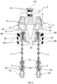
Figure 2 is a front view of the assistive device ofFigure 1 ; -
Figure 3 is a lateral view of the assistive device ofFigure 1 ; -
Figure 4 is a back view of the assistive device ofFigure 1 ; -
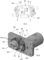
Figure 5 is a perspective view of an actuator of the assistive device ofFigure 1 ; -
Figure 6 is a perspective view of a detail of the actuator ofFigure 5 ; -
Figure 7 is a front view of the detail ofFigure 6 ; -
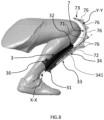
Figure 8 is a lateral view showing a chain and a calf garment of the assistive device ofFigure 1 ; -
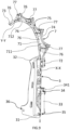
Figure 9 is a perspective view of the chain and of the calf garment ofFigure 8 ; -
Figure 10 is a perspective view of a detail of the chain ofFigure 7 andFigure 8 ; -
Figure 11 is a lateral view of the detail ofFigure 10 ; -
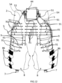
Figure 12 is a back view of a detail of the assistive device ofFigure 1 ; -
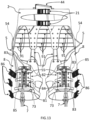
Figure 13 is a front view of a detail of the assistive device ofFigure 1 ; -
Figure 14 is a front view of a support element of the assistive device ofFigure 1 ; -
Figure 15 is a perspective view of an alternative embodiment of a detail of the support element offigure 14 ;-Figure 16 shows a front and a back view of an alternative embodiment of the assistive device ofFigure 1 ; -
Figure 17 shows two lateral views of the assistive device ofFigure 16 . - With reference to the attached figures,
numeral 1 designates a knee movement assistive device. - The
assistive device 1 comprises awaist garment 2 attachable to a user waist. For example, thewaist garment 2 comprises at least onefirst buckle 21. Preferably, thewaist garment 2 comprises a couple offirst buckles 21. As is per se know to the skilled person, thefirst buckles 21 allows thewaist garment 2 to be stably attached to a user waist. At the same time, thefirst buckles 21 allows to adjust thewaist garment 2 according to the specific dimension of the user waist, increasing the comfort of the user wearing saidwaist garment 2. - In addition, the
assistive device 1 comprises acalf garment 3 attachable to a user calf. For example, thecalf garment 3 comprises a couple ofjoint portions 36. Thejoint portion 36 can be clamped to a user calf, stably attaching thecalf garment 3 to the user calf. - The
calf garment 3 is arranged along a longitudinal direction X-X. When thecalf garment 3 is attached to a user calf, preferably, the longitudinal direction X-X overlaps to the direction defined by the user calf. Alternatively, when thecalf garment 3 is attached to a user calf, the longitudinal direction X-X defines a small relative angle with respect to the direction defined by the user calf. - The
assistive device 1 comprises anactuator 4 attached to thewaist garment 2 and comprising adriver 41. When thewaist garment 2 is attached to a user waist, theactuator 4 is preferably arranged on a back side of the user. As it is known to the skilled person, the back side of the user is the one defined by the back of the user. - Accordingly, the
driver 41 is configured to switch between an active state, wherein thedriver 41 generates a rotational force, and an idle state, wherein thedriver 41 generates a null force. In other words, in the idle state thedriver 41 generates no rotational force. - The
actuator 4 is configured to transform the rotational force of thedriver 41 in a tension force. - According to a preferred feature, the assistive device comprises rechargeable battery being configured to supply power to the
driver 41. - Preferably, the
assistive device 1 comprises abox 44. Thedriver 41 and the rechargeable battery are arranged inside thebox 44. Also thebox 44 is arranged on the back side of a user wearing theassistive device 1. - In addition, the
assistive device 1 comprises atransmission cable 5 connecting theactuator 4 to thecalf garment 3 and being configured to transmit the tension force, generated by transforming the rotational force of thedriver 41, to thecalf garment 3. The tension force transmitted to thecalf garment 3 assist the knee movement of a user. For example, the tension force, generated by transforming the rotational force of thedriver 41 and transmitted to thecalf garment 3, provide assistive torque to the knee joint when the user is bending the knee. - Preferably, the
transmission cable 5 has anupper end 51 connected to theactuator 4 and alower end 52 connected to thecalf garment 3. Still preferably, thetransmission cable 5 corresponds to a Bowden cable. - Still preferably, the
transmission cable 5 comprises acover housing 54 andinner cable 55 at least in part slidably channeled in thecover housing 54. - The
actuator 4 comprises afirst gear 42 connected to thedriver 41 and being configured to rotate around a first rotation center. The rotational force generated by thedriver 41 makes thefirst gear 42 rotate around the first rotation center. In other words, when thedriver 41 is in the active state thefirst gear 42 rotates around the first rotation center. - In addition, the
actuator 4 comprises asecond gear 43 operatively engaging thefirst gear 42 and being configured to rotate around a second rotation center. Thetransmission cable 5 is connected to thesecond gear 43. For example, theactuator 4 comprises apulley 45 connected to thesecond gear 43 and theinner cable 55 of thetransmission cable 5 is connected to thepulley 45. - Moreover, the
actuator 4 comprises locking means 6 operatively engaging the first 42 and the second 43 gears. - Preferably, the
first gear 42, thesecond gear 43 and the locking means 6 are mounted on asidewall 441 of thebox 44. - The locking means 6 are configured to switch between a locking configuration and a releasing configuration.
- In the locking configuration of the locking means 6, the
second gear 43 is prevented to rotate around the second rotation center. - In the releasing configuration of the locking means 6, the rotation of the
first gear 42 makes thesecond gear 43 rotate around the second rotation center so that the rotational force generated by thedriver 41 is transformed in the tension force and can be transmitted to thecalf garment 3 through thetransmission cable 5. In fact, being theinner cable 55 of thetransmission cable 5 attached to thesecond gear 43, the rotation of thesecond gear 43 pulls thetransmission cable 5 or release the pull action on thetransmission cable 5. In other words, depending on the specific rotation direction of thesecond gear 43, the rotational force of thedriver 41 is transformed in a first tension force acting as pull force or in a second tension force acting as a releasing force. The second tension force progressively release the first tension force, namely release the pull action transmitted to thecalf garment 3. In other words, the second tension force is opposite to the first tension force. - The locking means 6 are configured to switch from the locking configuration to the releasing configuration due to the rotation of the
first gear 42 when thedriver 41 is in the active state. Therefore, when thedriver 41 is in the active state, the tension force can be transmitted to thecalf garment 3 to assist the user knee movement. - In addition, the locking means 6 are configured to automatically switch from the releasing configuration to the locking configuration when the
driver 41 is switched to the idle state. Therefore, when thedriver 41 is switched to the idle state, being the locking means 6 in the locking configuration, the tension force generated from the rotational force of thedriver 41 is still transmitted to thecalf garment 3, without needing to maintain thedriver 41 in the active state. In other words, after the desired tension force has been transmitted to thecalf garment 3, thedriver 41 can be switched to the idle state letting the desired tension force still act on thecalf garment 3. - As a result, after the desired tension force is transmitted to the
calf garment 3, thedriver 41 can be switched to the idle state continuing assisting the user knee movement and reducing, therefore, the overall energy needed to assist the user knee movement with theassistive device 1. - According to a preferred embodiment of the invention, the
first gear 42 has a firstperimetral wall 421, arranged on a first circumferential direction. Namely, thefirst gear 41 has a circular shape. - In addition, the
first gear 42 has a plurality offirst teeth 422 arranged on said firstperimetral wall 421. Preferably, thefirs teeth 422 are equally spaced apart from each other along the first circumferential direction. The rotation of thefirst gear 42 around the first rotation center making thefirst teeth 422 move along the first circumferential direction. In other words, when thedriver 41 is in the active state, thefirst teeth 422 move along the first circumferential direction. - Preferably, the
first teeth 422 has a wedge shape. Still preferably, thefirst gear 42 has fifteenfirst teeth 422. - Still according to the preferred embodiment of the invention, the
second gear 43 has asecond perimetral wall 431, arranged on a second circumferential direction. Namely, also thesecond gear 43 has a circular shape. - In addition, the
second gear 43 has a plurality ofsecond teeth 432 arranged on thesecond perimetral wall 431. Preferably, thesecond teeth 432 are equally spaced apart from each other along the second circumferential direction. The rotation ofsecond gear 43 around the second rotation center making thesecond teeth 432 move along the second circumferential direction. - Preferably, the
second gear 43 has twenty-fivesecond teeth 432. - Accordingly, the rotation of the
first gear 42 in the releasing configuration of the locking means 6 makes eachfirst tooth 422 progressively engage a respectivesecond tooth 432 making thesecond gear 43 rotate around the second rotation center. - Still preferably, the
first gear 42 is configured to clockwise and anticlockwise rotate due to the rotational force generated by thedriver 41. It should be noted that, due to the progressively engagement of eachfirst tooth 422 with a respectivesecond tooth 432, the clockwise rotation of thefirst gear 42 is transformed in an anticlockwise rotation of thesecond gear 43, while the anticlockwise rotation of thefirst gear 42 is transformed in a clockwise rotation of thesecond gear 43. Namely, the rotation direction of thefirst gear 42 is preferably opposite to the rotation direction of thesecond gear 43. - It should be noted that, for example, an anticlockwise rotation of the
second gear 43 transformed the rotational force of thedriver 41 in the first tension force, pulling thetransmission cable 5, while a clockwise rotation of thesecond gear 43 transform the rotational force of thedriver 41 in the second tension force, releasing the pull action on thetransmission cable 5. - According to a preferred feature, each couple of
second teeth 432 is spaced apart by a respective separation distance along the second circumferential direction. Said separation distance is greater than the thickness of eachfirst tooth 422 along the first circumferential direction. - Given that the separation distance is greater than the thickness of each
first tooth 422, at least onefirst tooth 422 is interposed between a couple ofsecond teeth 432 and is spaced apart from each of saidsecond teeth 432 in the locking configuration of the locking means 6. The rotational force of thedriver 41 makes saidfirst tooth 422 engaging one of saidsecond teeth 432. - Therefore, before at least one
first tooth 422 engages asecond tooth 432, the rotation of thefirst gear 42, due to the rotational force of thedriver 41, switches the locking means 6 from the locking configuration to the releasing configuration. Namely, the locking means 6 are switched from the locking configuration to the releasing configuration before thefirst gear 42 makes thesecond gear 43 to rotate around the second rotation center. In this way, no rotation of thesecond gear 43 occurs when the locking means 6 are in the locking configuration. - According to the preferred embodiment of the invention, the locking means 6 comprises a
stopper 61 having afirst engagement portion 611. Preferably, thefirst engagement portion 611 has a tip shape. - The
stopper 61 is configured to assume in the locking configuration of the locking means 6 a locking position, wherein thefirst engagement portion 611 engages at least onesecond tooth 432. Preferably, in the locking position, thefirst engagement portion 611 is inserted between a couple ofsecond teeth 432. Therefore, when thestopper 61 is in the locking position thesecond gear 43 cannot rotate around the second rotation center. - At the same time, the
stopper 61 is configured to assume in the releasing configuration of the locking means 6 a releasing position, wherein thefirst engagement portion 611 is spaced apart from thesecond gear 43 along a direction transverse to the second circumferential direction. It should be noted that, when the locking means 6 are in the releasing configuration thestopper 61 is almost always in the releasing position so that thesecond gear 43 can rotate around the second rotation center without risking that asecond tooth 432 engages thefirst engagement portion 611. However, it could happen that in the releasing configuration of the locking means 6 asecond tooth 432 hits thefirst engagement portion 611, but without stopping the rotation of thesecond gear 43. - Preferably, the locking means 6 is configured to assume an intermediate configuration between the releasing configuration and the locking configuration. In said intermediate configuration, the
engagement portion 611 of thestopper 61 is inserted between a couple ofsecond teeth 432 and is spaced apart from saidsecond teeth 432. The passive clockwise rotation of thesecond gear 43 when the locking means 6 are in the intermediate configuration and thedriver 41 is in the idle state makes at least onesecond tooth 432 engage the first engagement portion of thestopper 611, switching the locking means 6 in the locking configuration, locking the rotation of thesecond gear 43. - According to the preferred embodiment of the invention, the locking means 6 comprises a
lever 62. Thelever 62 is configured to rotate around a third rotation center. - The
lever 62 extends between asecond engagement portion 621 and anopposite thrust portion 622 along an axis of thelever 62 passing through the third rotation center. Preferably, thethrust portion 622 has a tip shape. - The
thrust portion 622 engages thestopper 61. Preferably, thethrust portion 622 engages a receivingportion 612 of thestopper 61. - It should be noted that, the rotation of the
first gear 42 due to the rotational force of thedriver 41 makes thefirst gear 42 to engage thelever 62 at the secondengaging portion 621 to put thelever 62 in rotation around the third rotation center. At the same time, the rotation of thelever 62 around the third rotation center makes thethrust portion 622 exert a thrust action on thestopper 61 to switch thestopper 61 from the locking position to the releasing position. Namely, due to the rotation of thelever 62 thethrust portion 622 exerts a thrust action on the receivingportion 612 of thestopper 61, displacing thefirst engagement portion 611 away from thesecond gear 43. - When the
driver 41 is switched to the idle state, namely when thefirst gear 42 stops rotating, thethrust portion 622 stops exerting a thrust action on thestopper 41, making thefirst engagement portion 611 to progressively approach thesecond gear 43. In other words, after thedriver 41 is switched to the idle state, the locking means 6 can switch from the releasing configuration to the locking configuration or to the intermediate configuration and then to the locking configuration. - Preferably, the locking means 6 comprises a
spring 63 acting on thestopper 61. Thespring 63 makes thefirst engagement portion 611 to progressively engage thesecond gear 43, when thedriver 41 is switched to the idle state. In fact, thespring 63 always exert a pushing action on thefirst engagement portion 611 pushing saidfirst engagement portion 611 against thesecond gear 43. When thedriver 41 is switched to the active state, the thrust action of thethrust portion 622 acting on thestopper 61 wins the pushing action of thespring 63, displacing thefirst engagement portion 611 away from thesecond gear 43. When, thedriver 41 is switched to the idle state, thethrust portion 622 stops exerting a thrust action on thestopper 41, so that the pushing action of thespring 63 makes thefirst engagement portion 611 to progressively engage thesecond gear 43. - It should be noted that, preferably, the
thrust portion 622 of thelever 62 remains in contact with thestopper 61 both when the locking means 6 are in the locking configuration and in the releasing configuration, but also during the switching of the locking means 6 between the locking configuration and the releasing configuration. - It should be noted that, during the rotation of the
first gear 42, thefirst teeth 422 engages one by one thelever 62 at thesecond engagement portion 621, making thelever 62 to rotate around the third rotation center. - It should also be noted that, preferably, the clockwise rotation of the
first gear 42 makes thefirst gear 42 engage thesecond engagement portion 621 in a first contact area to anticlockwise rotate thelever 62. Namely, thefirst teeth 422 engage thesecond engagement portion 621 in the first contact area. - At the same time, still preferably, the anticlockwise rotation of the
first gear 42 makes thefirst gear 42 to engage thesecond engagement portion 621 in a second contact area to anticlockwise rotate thelever 62. Namely, thefirst teeth 422 engage thesecond engagement portion 621 in the second contact area. - Preferably, the rotation of the
first gear 42 around the first rotation center makes always thelever 62 to anticlockwise rotate around the third rotation center so that thethrust portion 622 exert the thrust action on thestopper 61. Namely, when thedriver 41 is in the active state, both the clockwise and the anticlockwise rotation of thefirst gear 42 switch the locking means 6 from the locking to the releasing configuration. In this way, the rotational force generated by thedriver 41 in the active state is always transferred to thecalf garment 3 in order to assist the knee movement, given that thesecond gear 43 can freely rotate around the second rotation center. - Preferably, the first contact area and second contact area are spaced apart from each other along the axes of the
lever 62. Still preferably, the distance of the first contact area from the third rotation center along the axes of thelever 62 is smaller than the distance of the second contact area from the third rotation center along the axes of thelever 62. - According to the preferred embodiment of the invention, the
second engagement portion 621 of thelever 62 has acurved edge 623 facing thefirst gear 42. Thecurved edge 623 has a recessedportion 624 and arounded portion 625. Preferably, the first contact area is placed on the left side of therounded portion 625, while the second contact area is placed on the right side of therounded portion 625. - It should be noted that, preferably, the anticlockwise rotation of the
lever 62 makes thestopper 61 to clockwise rotate around a fourth rotation center so that it is displaced from the locking position to the releasing position. Namely, following the rotation of thefirst gear 42 in the active state ofdriver 41, thestopper 61 clockwise rotate around the fourth rotation center. It should also be noted that, when thedriver 41 is switched from the active state to the idle state, thestopper 61 automatically anticlockwise rotates around the fourth rotation center so that the locking means 6 can be switched from the releasing configuration to the intermediate configuration or to the locking configuration. - Preferably, the
first engagement portion 611 and the receivingportion 612 of thestopper 61 are opposite to each other with respect to the fourth rotation center. - According to the preferred embodiment of the invention, the
stopper 61 and thelever 62 have the shape reported inFigure 6 . The shape of thestopper 61 and thelever 62 is partially visible also inFigure 5 . - According to the preferred embodiment of the invention, the
actuator 4 comprises a control unit in signal communication with thedriver 41 and with an external device. The control unit is configured to switch thedriver 41 between the idle state and the working state upon receival of a command signal by the control unit coming from the external device. In other words, it is possible to actively control thedriver 41 so that the tension force is transmitted to thecalf garment 3 by means of an external device, assisting the user knee movement. - Still according to the preferred embodiment of the invention, the
assistive device 1 comprises achain 7. Preferably, thechain 7 is interposed between thewaist garment 2 and thecalf garment 3. Still preferably, when a user is wearing theassistive device 1, the chain is arranged on a front side of the user. As it per se known to the skilled person, the front side of a user is opposite to the back side of the user. - The
chain 7 comprises amodular body 71 having afixed end 72, attached to thecalf garment 3, afree end 73 and anupper surface 74 connecting thefixed end 72 and thefree end 73. Preferably, thefree end 73 is facing thewaist garment 2. When a user is wearing theassistive device 1, the upper surface is facing away with respect to the leg of the user. - The
modular body 71 comprises agroove 75 defined on theupper surface 74. Thetransmission cable 5 is slidably channeled in thegroove 75. Preferably, only theinner cable 55 of thetransmission cable 5 is slidably channeled in thegroove 75. Being thetransmission cable 5 slidably channeled in thegroove 75, thetransmission cable 5 can transmit the tension force to thecalf garment 3. - According to a preferred feature, the
chain 7 is configured to switch between a an initial configuration and a limiting configuration. - In the initial configuration of the
chain 7, thefixed end 72 and thefree end 73 of themodular body 71 are at a first distance. Preferably, the first distance is the maximum distance between thefixed end 72 and thefree end 73. - In the limiting configuration of the chain, the
modular body 71 is arranged along a curvature direction Y-Y defining a curvature angle with respect to the longitudinal direction X-X such that thefixed end 72 and thefree end 73 of themodular body 71 are at a second distance. The second distance is smaller than the first distance. Namely, when thechain 7 is in the limiting configuration thefixed end 72 and thefree end 73 are spaced apart from each other along the curvature direction Y-Y. Preferably, the second distance is the minimum distance between thefixed end 72 and thefree end 73. - The bending of the user knee switches the
modular body 71 of thechain 7 between the initial configuration and the limiting configuration. In other word, themodular body 71 of thechain 7 follows the bending of the knee of the user wearing theassistive device 1. - It should be noted that, preferably, when a user is wearing the
assistive device 1 and thechain 7 is switched from the initial configuration to the limiting configuration it means that the user is assisted in moving from a stand up position to a bent position. At the same time, still preferably, when the user is wearing theassistive device 1 and thechain 7 is switched from the limiting configuration to the initial configuration it means that the user is assisted in moving from a bent position to a stand up position. - It should be noted that, given that the
chain 7 guides thetransmission cable 5 during the knee movement, thechain 7 avoids applying any force directly on the knee joint of the user wearing theassistive device 1. Therefore, thechain 7 avoids interferences and discomfort during use of theassistive device 1. - At the same time, the
chain 7 generates a fully deterministic assistive torque, due to the switching of thechain 7 from the initial configuration to the limiting configuration that permits to route thetransmission cable 5 along a desired path around the knee joint of the user wearing theassistive device 1. - Therefore, the
chain 7 is used to guide thetransmission cable 5 and optimize the moment arm to generate the desired assistive torque and knee flexion angle profile. In order words, thechain 7 contributes in assisting the user knee movement. - According to the preferred embodiment of the invention, the
modular body 71 of thechain 7 comprises at least one modular unit. Each modular unit comprises a first and a secondrigid elements 76 connected together to define, at least in part, thegroove 75 of themodular body 71. Preferably, eachrigid element 76 comprises a respective portion of thegroove 75 of themodular body 71 and the joining of all said portions defines thegroove 75. - Preferably, the
modular body 71 comprises fiverigid elements 76 arranged in four modular units. In fact, if arigid element 76 is interposed between other tworigid elements 76, it belongs to two different modular units. In other words, if arigid element 76 is interposed between other tworigid elements 76, saidrigid element 76 defines a first modular unit, wherein it works as a secondrigid element 76, with the precedingrigid element 76, and it defines a second modular unit, wherein it works as firstrigid element 76, with the succeedingrigid elements 76. Namely, eachrigid element 76 defines a respective modular unit with each adjacentrigid element 76. - Still preferably, each
rigid element 76 is arranged along the curvature direction Y-Y and extends between afirst edge 761 and an oppositesecond edge 762 with respect to the curvature direction Y-Y. - The first and the second
rigid elements 76 of each modular unit are connected together such that in the initial configuration of thechain 7 thesecond edge 762 of the firstrigid element 76 and thefirst edge 761 of the secondrigid element 76 are facing together and spaced apart from each other. Namely, being thesecond edge 762 of the firstrigid element 76 and thefirst edge 761 of the secondrigid element 76 spaced apart from each other in the initial configuration of thechain 7, thefixed end 72 and thefree end 73 of themodular body 71 are, preferably, at the maximum distance between each other. - At the same time, the first and the second
rigid elements 76 of each modular unit are connected together such that in the limiting configuration of thechain 7 thesecond edge 762 of the firstrigid element 76 and thefirst edge 761 of the secondrigid element 76 are in contact making themodular body 71 of thechain 7 to be arranged along the curvature direction Y-Y. In fact, given that each rigid element is arranged along the curvature direction Y-Y, in the limiting configuration also the wholemodular body 71 defined by therigid elements 76 is arranged along the curvature direction Y-Y. - Therefore, switching from the initial configuration to the limiting configuration the
fixed end 72 and thefree end 73 of themodular body 71 progressively approaching to reach the minimum distance at the limiting configuration. - Accordingly to the preferred embodiment of the invention, each
rigid element 76 extends between a base 763 and an opposite top 764 with respect to a direction transverse to the curvature direction Y-Y. - In addition, each
rigid element 76 has at least one throughhole 765 placed near the top 764. Preferably, eachrigid element 76 has onetrough hole 765 for each modular unit to which it belongs. Still preferably, the throughholes 765 of eachrigid element 76 are placed above the respective portion of thegroove 75 of saidrigid element 76. - Moreover, preferably, the
chain 7 comprises onepin 77 for each modular unit. Eachpin 77 is inserted in the throughholes 765 of the first and secondrigid elements 76 of a respective modular unit connecting the first and secondrigid elements 76 of said modular unit together. Namely, the first and secondrigid elements 76 of each modular units are hinged together at a connection point resulting from the overlapping of the throughholes 765 of the first and secondrigid elements 76 of said modular unit. - It should be noted that during the switching from the initial configuration to the limiting configuration of the
chain 7, the first and the secondrigid elements 76 of each respective modular unit are approaching each other by rotating around their respective connection point. - According to the preferred embodiment of the invention, the
modular body 71 of thechain 7 comprises afirst portion 711 placed near thefixed end 72 and asecond portion 712 placed near thefree end 73. - Preferably, the
first portion 711 of thechain 7 is arranged along a portion of an ellipse and thesecond portion 712 of thechain 7 is arranged along a portion of a circle internally tangent to the ellipse in a tangent point when thechain 7 is in the limiting configuration. Given this specific arrangement of the first 711 and second 712 portions of thechain 7, there is no interaction between the human knee and thechain 7. - It should also be noted that, by changing the parameters of the ellipse and of the circle internally tangent to the ellipse, different profiles of the
chain 7 in the limiting configuration can be obtained. By changing the profile of thechain 7 in the limiting configuration, the performance of theassistive device 1 can be optimized and, at the same time, it can be adapted to different users. - According to the preferred embodiment of the invention, the
calf garment 3 extends between abottom portion 31 and an oppositetop portion 32 along the longitudinal direction X-X. When a user is wearing theassistive device 1, thebottom portion 31 of thecalf garment 3 is placed near the ankle of the user. - Preferably, the
calf garment 3 comprises anelastic element 33 extending between afirst end 34 and an oppositesecond end 35 along the longitudinal direction X-X. For example, theelastic element 33 is a rubber belt. Still preferably, when a user is wearing theassistive device 1, the elastic element is arranged on the front side of a user. - Still preferably, the
transmission cable 5 is connected to thefirst end 34 of theelastic element 33. More preferably, thelower end 52 of thetransmission cable 5 is connected to thefirst end 34 of theelastic element 33. For example, thefirst end 34 of theelastic element 33 comprises anend connector 341. It should be noted that, preferably, thelower end 52 of thetransmission cable 5 is defined on itsinner cable 55. At the same time, preferably, theupper end 51 of thetransmission cable 5 is defined on itsinner cable 55. - Preferably, the
second end 35 of theelastic element 33 is connected to thebottom portion 31 of thecalf garment 3. Namely, theelastic element 33 connects thelower end 52 of thetransmission cable 5 to thebottom portion 31 of thecalf garment 3. - Still preferably, the
fixed end 72 of themodular body 71 of thechain 7 is attached to thetop portion 32 of thecalf garment 3. - According to a preferred feature, the
elastic element 33 is configured to switch between a rest configuration and an extended configuration, the distance between the first 34 and the second 35 ends along the longitudinal direction X-X increasing from the rest configuration to the extended configuration. - As already described, the
actuator 4 is configured to transform the rotational force of thedriver 41 in a first tension force, acting as a pull force, and in a second tension force, acting as a releasing force. The first tension force transmitted to thecalf garment 3 is configured to switch theelastic element 33 from the rest configuration to the extended configuration. At the same time, the second tension force transmitted to thecalf garment 3 is configured to allow theelastic element 33 to switch from the extended to the rest configuration due to the elastic return of theelastic element 33. - It should be noted that, preferably, as the tension force generated by the
actuator 4 switch theelastic element 33 from the rest to the extend configuration and as the user wearing theassistive device 1 switches from a stand up position to a bent position, thechain 7 is simultaneously switched from the initial configuration to the limiting configuration. At the same time, as the tension force generated by theactuator 4 allow theelastic element 33 to switch from the extended configuration to the rest configuration and as the user wearing theassistive device 1 switches from a bent position to a stand up position, thechain 7 is simultaneously switched from the limiting configuration to the initial configuration. - It should be also noted that, when a user is wearing the
assistive device 1 and theelastic element 33 is in the rest configuration the user is in a stand up position. On the other hand, when theelastic element 33 is in the extended configuration the user is in a bent position. In other word, by switching theelastic element 33 from the rest configuration to the extended configuration and viceversa, the user is assisted in doing, for example, a squat. - According to the preferred embodiment of the invention, the
assistive device 1 comprises athigh garment 8 attachable to a user thigh. For example, thethigh garment 8 comprises at least onesecond buckle 86. Preferably, thethigh garment 2 comprises threesecond buckles 86. As is per se know to the skilled person, the second buckles 86 allows thethigh garment 8 to be stably attached to a user thigh. At the same time, the second buckles 86 allows to adjust thethigh garment 8 according to the specific dimension of the user thigh, increasing the comfort of the user wearing saidthigh garment 8. - As the
thigh garment 8 is attachable to a user thigh, when the user is wearing theassistive device 1, thethigh garment 8 is interposed between thewaist garment 2 and thecalf garment 3. - Preferably, the
thigh garment 8 comprises asupport element 81. When a user is wearing thethigh garment 8, thesupport element 81 is placed on the front side of a user. - The
transmission cable 5 is slidably channeled in thesupport element 81. Advantageously, thesupport element 81 of the thigh garment allows a better transmission of the tension force generated by theactuator 4 to thecalf garment 3. - Preferably, the
cover housing 54 of thetransmission cable 5 connects thebox 44 to thesupport element 81. In other word, preferably, theinner cable 55 of thetransmission cable 5 is channeled in thecover housing 54 only between thebox 44 and thesupport element 81. - Still preferably, the
free end 73 of themodular body 71 of thechain 71 faces thethigh garment 8. Namely, thechain 7 is configured to be interposed between thethigh garment 8 and thecalf garment 3. - According to the preferred embodiment of the invention, the
thigh garment 8 comprises abody portion 82 having a plurality of first joiningelements 83. Preferably, thesupport element 81 comprises aplate 84 having a plurality of second joiningelements 85. Each second joiningelement 85 is connected to a respective first joiningelement 83 to stably attach thesupport element 81 to thebody portion 82 of thethigh garment 8. By disconnecting the second joiningelements 85 and the first joiningelements 83 it is possible to remove thesupport element 81 from thebody portion 82 of thethigh garment 8. - For example, each first joining
element 83 correspond to a strap or a belt, while each second joiningelement 85 corresponds to a fin insertable in a respective strap or a slot configured to receive a respective belt. - Still according to the preferred embodiment of the invention, the
assistive device 1 comprises a plurality of first elastic robs 9 connecting thewaist garment 2 to thethigh garment 8. Therefore the first elastic robs 9 prevents the sliding down of thethigh garment 8 with respect to thewaist garment 2 during the use of theassistive device 1. Therefore, the first elastic robs 9 increase the comfort of a user wearing theassistive device 1. - According to the preferred embodiment of the invention, both the
waist garment 2 and thethigh garment 8 comprises a plurality of respective second elastic robs 91. Each second elastic rob 91 is disposed transversally to the first elastic robs 9. It should be noted that the second elastic rob 91 of thewaist garment 2 are used to maintain the shape of thewaist garment 2 when a user is wearing theassistive device 1. At the same time, the second elastic rob 91 of thethigh garment 8 are used to maintain the shape of thethigh garment 8 when a user is wearing theassistive device 1. - According to a preferred embodiment, the assistive device comprises first straps 22 and
second straps 23 connecting thewaist garment 2 to thethigh garment 8. Preferably, when a user is wearing theassistive device 1 thefirst straps 22 are arranged on the front side of the user, while thesecond straps 23 are arranged on the back side of the user. Both thefirst straps 22 and thesecond straps 23 are arranged in a triangular shape, with one attachment point on thethigh garment 8 and two attachments points on thewaist garment 2. - It should be noted that, the first straps 22 defines a first trace A for the load distribution, while the
second straps 23 together with thethigh garment 8 defines a second trace B for the load distribution. Advantageously, the first 22 and second 23 straps can provide a stable support for thetransmission cable 5 and distribute the high tension force to the upper thigh and hip of the user wearing theassistive device 1. For example, if a user wearing theassistive device 1 is performing a squat motion, the load distribution switches between the first trace A and a second trace B. - At the beginning of squat, the first trace A will deliver the load to the
waist garment 2 while the second trace B is loose. With the increase of the squat depth, the first trace A gradually becomes loose and the tension load will deliver to the backside of thewaist garment 2 via the second trace B that has the additional benefit of also generating a positive torque around the hip supporting this joint during deep squat and during the transition from a squat to a standing posture. - It is also an object of the present invention, an exoskeleton comprising two
assistive devices 1 corresponding to theassistive device 1 described above. Eachassistive device 1 of the exoskeleton is used to assist the movement of a corresponding user knee. - Preferably, the
actuator 41 of the twoassistive devices 1 are arranged in thesame box 44. Still preferably, thewaist garment 2 can be the same for bothassistive devices 1 of the exoskeleton.
Claims (10)
- A knee movement assistive device (1), comprising:- a waist garment (2) attachable to a user waist and a calf garment (3) attachable to a user calf, said calf garment (3) being arranged along a longitudinal direction (X-X);- an actuator (4) attached to the waist garment (2) and comprising a driver (41), said driver (41) being configured to switch between an active state, wherein the driver (41) generates a rotational force, and an idle state, wherein the driver (41) generates a null force, the actuator (4) being configured to transform the rotational force of the driver in a tension force;- a transmission cable (5) connecting the actuator (4) to the calf garment (3) and being configured to transmit the tension force, generated by transforming the rotational force of the driver (41), to the calf garment (3);said assistive device (1) being configured in that the actuator (4) comprises:- a first gear (42) connected to the driver (41) and being configured to rotate around a first rotation center, the rotational force generated by the driver (41) making the first gear (42) rotate around the first rotation center;- a second gear (43) operatively engaging the first gear (42) and being configured to rotate around a second rotation center, the transmission cable (5) being connected to said second gear (43);- locking means (6) operatively engaging the first (42) and the second (43) gears; said locking means (6) being configured to switch between a locking configuration, wherein the second gear (43) is prevented to rotate around the second rotation center, and a releasing configuration, wherein the rotation of the first gear (42) makes the second gear (43) rotate around the second rotation center so that the rotational force generated by the driver (41) is transformed in the tension force and can be transmitted to the calf garment (3) through the transmission cable (5), the locking means (6) being configured to switch from the locking configuration to the releasing configuration due to the rotation of the first gear (42) when the driver (41) is in the active state, said locking means (6) being configured to automatically switch from the releasing configuration to the locking configuration when the driver (41) is switched to the idle state.
- Assistive device (1) according to claim 1, wherein:- the first gear (42) has a first perimetral wall (421), arranged on a first circumferential direction, and a plurality of first teeth (422) arranged on said first perimetral wall (421), the rotation of the first gear (42) around the first rotation center making the first teeth (422) move along the first circumferential direction;- the second gear (43) has a second perimetral wall (431), arranged on a second circumferential direction, and a plurality of second teeth (432) arranged on said second perimetral wall (431), the rotation of second gear (43) around the second rotation center making the second teeth (432) move along the second circumferential direction;- the rotation of the first gear (42) in the releasing configuration of the locking means (6) makes each first tooth (422) progressively engage a respective second tooth (432) making the second gear (43) rotate around the second rotation center.
- Assistive device (1) according to claim 2, wherein:- each couple of second teeth (432) is spaced apart by a respective separation distance along the second circumferential direction, said separation distance being greater than the thickness of each first tooth (422) along the first circumferential direction;- at least one first tooth (422) is interposed between a couple of second teeth (432) and is spaced apart from each of said second teeth (432) in the locking configuration of the locking means (6), the rotational force of the driver (41) making said first tooth (422) engaging one of said second teeth (432).
- Assistive device according to claim 2 or 3, wherein:- the locking means (6) comprises a stopper (61) having a first engagement portion (611), said stopper (61) being configured to assume in the locking configuration of the locking means (6) a locking position, wherein the first engagement portion (611) engages at least one second tooth (432), and being configured to assume in the releasing configuration of the locking means (6) a releasing position, wherein said first engagement portion (611) is spaced apart from the second gear (43) along a direction transverse to the second circumferential direction.
- Assistive device according to claim 4, wherein:- the locking means (6) comprises a lever (62) being configured to rotate around a third rotation center, said lever (62) extending between a second engagement portion (621) and an opposite thrust portion (622) along an axis of the lever (62) passing through the third rotation center, said thrust portion (622) engaging the stopper (61), the rotation of the first gear (42) due to the rotational force of the driver (41) making the first gear (42) to engage the lever (62) at the second engaging portion (621) to put the lever (62) in rotation around the third rotation center, the rotation of the lever (62) around the third rotation center making the thrust portion (622) exert a thrust action on the stopper (61) to switch the stopper (61) from the locking position to the releasing position.
- Assistive device (1) according to claim 5, wherein:- the first gear (42) is configured to clockwise and anticlockwise rotate due to the rotational force generated by the driver (41);- the clockwise rotation of the first gear (42) makes said first gear (42) engage the second engagement portion (621) in a first contact area to anticlockwise rotate the lever (62);- the anticlockwise rotation of the first gear (42) makes said first gear (42) to engage the second engagement portion (621) in a second contact area to anticlockwise rotate the lever (62):- the first contact area and second contact area being spaced apart from each other along the axes of the lever (62).
- Assistive device according to claim 6, wherein the second engagement portion (621) of the lever (62) has a curved edge (623) facing the first gear (42), said curved edge (623) having a recessed portion (624) and a rounded portion (625), the first contact area being placed on the left side of the rounded portion (625), the second contact area being placed on the right side of said rounded portion (625).
- Assistive device (1) according to claim 6 or 7, wherein the anticlockwise rotation of the lever (62) makes the stopper (61) to clockwise rotate around a fourth rotation center so that it is displaced from the locking position to the releasing position.
- Assistive device (1) according to any claim 1 to 8, wherein:- the calf garment (3) extends between a bottom portion (31) and an opposite top portion (32) along the longitudinal direction (X-X), said calf garment (3) comprising an elastic element (33) extending between a first end (34) and an opposite second end (35) along the longitudinal direction (X-X), the transmission cable (5) being connected to the first end (34) of the elastic element (33), the second end (35) of the elastic element (33) being connected to the bottom portion (31) of the calf garment (3), said elastic element (33) being configured to switch between a rest configuration and an extended configuration, the distance between the first (34) and the second (35) ends along the longitudinal direction (X-X) increasing from the rest configuration to the extended configuration;- the actuator (4) is configured to transform the rotational force of the driver (41) in a first tension force, acting as a pull force, and in a second tension force, acting as a releasing force; the first tension force transmitted to the calf garment (3) being configured to switch the elastic element (33) from the rest configuration to the extended configuration, the second tension force transmitted to the calf garment (3) being configured to allow the elastic element (33) to switch from the extended to the rest configuration due to the elastic return of the elastic element (33).
- Assistive device (1) according to any claim 1 to 9, wherein the actuator (4) comprises a control unit in signal communication with the driver (41) and with an external device, said control unit being configured to switch the driver (41) between the idle state and the working state upon receival of a command signal by the control unit coming from the external device.
Applications Claiming Priority (2)
| Application Number | Priority Date | Filing Date | Title |
|---|---|---|---|
| IT102021000015596A IT202100015596A1 (en) | 2021-06-15 | 2021-06-15 | Knee motion assist device |
| PCT/IB2022/055011 WO2022263957A1 (en) | 2021-06-15 | 2022-05-27 | A knee movement assistive device |
Publications (3)
| Publication Number | Publication Date |
|---|---|
| EP4355283A1 EP4355283A1 (en) | 2024-04-24 |
| EP4355283C0 EP4355283C0 (en) | 2025-07-02 |
| EP4355283B1 true EP4355283B1 (en) | 2025-07-02 |
Family
ID=77519689
Family Applications (1)
| Application Number | Title | Priority Date | Filing Date |
|---|---|---|---|
| EP22728980.8A Active EP4355283B1 (en) | 2021-06-15 | 2022-05-27 | A knee movement assistive device |
Country Status (4)
| Country | Link |
|---|---|
| US (1) | US20240277548A1 (en) |
| EP (1) | EP4355283B1 (en) |
| IT (1) | IT202100015596A1 (en) |
| WO (1) | WO2022263957A1 (en) |
Family Cites Families (48)
| Publication number | Priority date | Publication date | Assignee | Title |
|---|---|---|---|---|
| US5178137A (en) * | 1990-03-16 | 1993-01-12 | Motus, Inc. | Segmented dynamic splint |
| JP2002301124A (en) * | 2001-04-06 | 2002-10-15 | Honda Motor Co Ltd | Walking aid |
| US7758481B2 (en) * | 2002-09-04 | 2010-07-20 | Denis Burke Drennan | Dynamic hip stabilizer |
| US7497808B2 (en) * | 2006-01-12 | 2009-03-03 | Paul William Eschenbach | Step thru recumbent elliptical exercise apparatus |
| US20100179034A1 (en) * | 2009-01-12 | 2010-07-15 | Leao Wang | Position-limiting apparatus of a pendulum mechanism of an exercise equipment |
| IT1394621B1 (en) * | 2009-01-23 | 2012-07-05 | Fond Istituto Italiano Di Tecnologia | LINEAR ACTUATOR AND REHABILITATION DEVICE INCORPORATING SUCH ACTUATOR. |
| IT1393776B1 (en) * | 2009-04-03 | 2012-05-08 | Fond Istituto Italiano Di Tecnologia | ELASTIC ROTARY ACTUATOR, PARTICULARLY FOR ROBOTIC APPLICATIONS, AND METHOD FOR ITS CONTROL |
| US9308414B2 (en) * | 2011-04-26 | 2016-04-12 | Virginia Commonwealth University | Elliptically based robotic gait trainer (EBRGT) |
| ITTO20110848A1 (en) * | 2011-09-23 | 2013-03-24 | Fond Istituto Italiano Di Tecnologia | ELASTIC ROTARY ACTUATOR. |
| CN104869969B (en) * | 2012-09-17 | 2017-06-09 | 哈佛大学校长及研究员协会 | Soft exosuits for assisting human locomotion |
| WO2014151584A1 (en) * | 2013-03-15 | 2014-09-25 | Alterg, Inc. | Orthotic device drive system and method |
| KR20160016925A (en) * | 2013-05-31 | 2016-02-15 | 프레지던트 앤드 펠로우즈 오브 하바드 칼리지 | Soft exosuit for assistance with human motion |
| US9333107B2 (en) * | 2013-08-15 | 2016-05-10 | Google Inc. | Brace system |
| JP5927173B2 (en) * | 2013-12-27 | 2016-06-01 | 本田技研工業株式会社 | Joint mechanism |
| KR102241853B1 (en) * | 2014-03-28 | 2021-04-19 | 삼성전자주식회사 | Joint assembly and walking aid robot having the same |
| KR101693976B1 (en) * | 2015-04-08 | 2017-01-09 | 현대자동차주식회사 | Apparatus for assisting muscle strength |
| KR102541908B1 (en) * | 2015-07-21 | 2023-06-09 | 삼성전자주식회사 | A frame module and a motion assist apparatus comprising thereof |
| JP2017065484A (en) * | 2015-09-30 | 2017-04-06 | アイシン精機株式会社 | Vehicle seat lifter |
| JP2019534762A (en) * | 2016-08-23 | 2019-12-05 | セイスミック ホールディングス インコーポレイテッド | System and method for a portable powered stretch exterior suit |
| US11020261B2 (en) * | 2016-08-23 | 2021-06-01 | Seismic Holdings, Inc. | Patch systems for use with assistive exosuit |
| IT201600099694A1 (en) * | 2016-10-05 | 2018-04-05 | Fondazione St Italiano Tecnologia | Exoskeleton for lower limbs |
| JP2018094635A (en) * | 2016-12-08 | 2018-06-21 | ボッシュ株式会社 | Motion assisting device |
| CN108326878A (en) * | 2017-01-18 | 2018-07-27 | 王怀亮 | A kind of limb action electronic switching equipment, instruction identification method and recording/playback method |
| US10870198B1 (en) * | 2017-03-21 | 2020-12-22 | Virginia Tech Intellectual Properties, Inc. | Back exoskeleton to assist lifting |
| IT201700084346A1 (en) * | 2017-07-24 | 2019-01-24 | Scuola Superiore Santanna | ASSISTABLE WALKING ASSISTED DEVICE |
| JP2019043443A (en) * | 2017-09-05 | 2019-03-22 | トヨタ紡織株式会社 | Lifter device |
| KR20190109982A (en) * | 2018-03-19 | 2019-09-27 | 엘지전자 주식회사 | Muscular strength assist device improved battery storage structure |
| CN109528451B (en) * | 2018-09-14 | 2019-10-08 | 华中科技大学 | A kind of passive exoskeleton device of hip knee doublejointed based on clutch timesharing regulation |
| CN109223454B (en) * | 2018-09-29 | 2021-03-26 | 北京精密机电控制设备研究所 | A mechanical structure of waist-assisted movement of a power-assisted exoskeleton robot |
| CN111096873B (en) * | 2018-10-25 | 2022-08-30 | 深圳市肯綮科技有限公司 | Portable inhaul cable driving power assisting device |
| US12240108B2 (en) * | 2019-04-22 | 2025-03-04 | Iuvo S.R.L. | System for assisting an operator in exerting efforts |
| CN110063875B (en) * | 2019-05-22 | 2021-05-18 | 东北大学 | An exoskeleton robot for whole body rehabilitation training |
| CN110202549A (en) * | 2019-06-27 | 2019-09-06 | 迈宝智能科技(苏州)有限公司 | The wearable assistance exoskeleton of hard and soft combination drive |
| CN110193819A (en) * | 2019-06-27 | 2019-09-03 | 迈宝智能科技(苏州)有限公司 | Adaptive knee-joint mechanism and device for wearable ectoskeleton |
| CN110653796B (en) * | 2019-09-11 | 2022-09-13 | 西北机电工程研究所 | Flexible exoskeleton power-assisted robot |
| CN110742777A (en) * | 2019-10-14 | 2020-02-04 | 北京大学 | Flexible structure driven by flexible wires, chain link and wearing device |
| CN111102147B (en) * | 2019-12-16 | 2021-04-13 | 西北工业大学 | Flexible exoskeleton assisting in energy collection management and migration of lower limbs of human body |
| CN111388279B (en) * | 2020-02-21 | 2025-07-11 | 南方科技大学 | Flexible walking exoskeleton |
| CN111481402B (en) * | 2020-04-24 | 2022-02-01 | 合肥工业大学 | Knee joint exoskeleton based on rope variable-stiffness multifunctional driver and control method |
| CN111449915B (en) * | 2020-04-26 | 2024-10-01 | 南方科技大学 | Hip-knee double-joint walking-assisting exoskeleton |
| CN111588587B (en) * | 2020-05-08 | 2021-04-30 | 燕山大学 | Lower limb rehabilitation robot capable of balancing its own weight and method of using the same |
| CN111888187B (en) * | 2020-07-24 | 2021-06-11 | 华中科技大学 | Active type knee hyperextension lower limb rehabilitation exoskeleton device |
| CN112022618B (en) * | 2020-09-03 | 2024-04-19 | 河北工业大学 | Rigid-flexible coupling wearable walking assisting exoskeleton system |
| DE202020106660U1 (en) * | 2020-11-19 | 2020-12-04 | Dominik Heinzelmann | Lifting aid |
| CN112515921B (en) * | 2020-11-27 | 2022-02-25 | 上海交通大学 | A flexible lower limb rehabilitation robot for assisting stroke patients to restore gait |
| CN112773668B (en) * | 2021-01-29 | 2025-03-11 | 武汉软件工程职业学院(武汉开放大学) | A knee joint assisting rehabilitation device |
| CN112914954A (en) * | 2021-02-26 | 2021-06-08 | 安徽中医药大学 | Wearable lower limb rehabilitation exoskeleton robot |
| CN114931488A (en) * | 2022-06-02 | 2022-08-23 | 漯河市中心医院(漯河市第一人民医院、漯河医学高等专科学校第一附属医院) | Recovered device of taking exercise of severe patient's treatment shank function |
-
2021
- 2021-06-15 IT IT102021000015596A patent/IT202100015596A1/en unknown
-
2022
- 2022-05-27 US US18/569,629 patent/US20240277548A1/en active Pending
- 2022-05-27 WO PCT/IB2022/055011 patent/WO2022263957A1/en not_active Ceased
- 2022-05-27 EP EP22728980.8A patent/EP4355283B1/en active Active
Also Published As
| Publication number | Publication date |
|---|---|
| EP4355283A1 (en) | 2024-04-24 |
| WO2022263957A1 (en) | 2022-12-22 |
| EP4355283C0 (en) | 2025-07-02 |
| US20240277548A1 (en) | 2024-08-22 |
| IT202100015596A1 (en) | 2022-12-15 |
Similar Documents
| Publication | Publication Date | Title |
|---|---|---|
| US11826302B2 (en) | Wearable robotic device | |
| EP1637116B1 (en) | Walk assisting device | |
| EP3806807B1 (en) | Systems and devices for assistive mobility | |
| EP1637112B1 (en) | Walking aid device | |
| EP3120824B1 (en) | Frame module and motion assistance apparatus including the same | |
| EP3449889B1 (en) | Motion assistance apparatus | |
| KR20170052374A (en) | A driving module and a motion assist apparatus comprising thereof | |
| WO2011008677A1 (en) | Orthotic device with removably attachable actuator | |
| EP3958814B1 (en) | Locking and adjustment mechanism for exoskeleton | |
| EP4355284B1 (en) | A knee movement assistive device | |
| US20240277548A1 (en) | A knee movement assistive device | |
| JP4112541B2 (en) | Wearing device for walking assist device | |
| EP4140463B1 (en) | Wearing module and motion assistance device comprising same | |
| CA3103434C (en) | Systems and devices with elastically deformable members for assistive mobility | |
| EP4611710A1 (en) | Active pelvic orthosis including a physical human-robot interface |
Legal Events
| Date | Code | Title | Description |
|---|---|---|---|
| STAA | Information on the status of an ep patent application or granted ep patent |
Free format text: STATUS: UNKNOWN |
|
| STAA | Information on the status of an ep patent application or granted ep patent |
Free format text: STATUS: THE INTERNATIONAL PUBLICATION HAS BEEN MADE |
|
| PUAI | Public reference made under article 153(3) epc to a published international application that has entered the european phase |
Free format text: ORIGINAL CODE: 0009012 |
|
| STAA | Information on the status of an ep patent application or granted ep patent |
Free format text: STATUS: REQUEST FOR EXAMINATION WAS MADE |
|
| 17P | Request for examination filed |
Effective date: 20231215 |
|
| AK | Designated contracting states |
Kind code of ref document: A1 Designated state(s): AL AT BE BG CH CY CZ DE DK EE ES FI FR GB GR HR HU IE IS IT LI LT LU LV MC MK MT NL NO PL PT RO RS SE SI SK SM TR |
|
| DAV | Request for validation of the european patent (deleted) | ||
| DAX | Request for extension of the european patent (deleted) | ||
| GRAP | Despatch of communication of intention to grant a patent |
Free format text: ORIGINAL CODE: EPIDOSNIGR1 |
|
| STAA | Information on the status of an ep patent application or granted ep patent |
Free format text: STATUS: GRANT OF PATENT IS INTENDED |
|
| INTG | Intention to grant announced |
Effective date: 20250103 |
|
| GRAS | Grant fee paid |
Free format text: ORIGINAL CODE: EPIDOSNIGR3 |
|
| GRAA | (expected) grant |
Free format text: ORIGINAL CODE: 0009210 |
|
| STAA | Information on the status of an ep patent application or granted ep patent |
Free format text: STATUS: THE PATENT HAS BEEN GRANTED |
|
| AK | Designated contracting states |
Kind code of ref document: B1 Designated state(s): AL AT BE BG CH CY CZ DE DK EE ES FI FR GB GR HR HU IE IS IT LI LT LU LV MC MK MT NL NO PL PT RO RS SE SI SK SM TR |
|
| REG | Reference to a national code |
Ref country code: GB Ref legal event code: FG4D |
|
| REG | Reference to a national code |
Ref country code: CH Ref legal event code: EP |
|
| REG | Reference to a national code |
Ref country code: DE Ref legal event code: R096 Ref document number: 602022016922 Country of ref document: DE |
|
| REG | Reference to a national code |
Ref country code: IE Ref legal event code: FG4D |
|
| U01 | Request for unitary effect filed |
Effective date: 20250722 |
|
| U07 | Unitary effect registered |
Designated state(s): AT BE BG DE DK EE FI FR IT LT LU LV MT NL PT RO SE SI Effective date: 20250728 |
|
| PG25 | Lapsed in a contracting state [announced via postgrant information from national office to epo] |
Ref country code: IS Free format text: LAPSE BECAUSE OF FAILURE TO SUBMIT A TRANSLATION OF THE DESCRIPTION OR TO PAY THE FEE WITHIN THE PRESCRIBED TIME-LIMIT Effective date: 20251102 |
|
| PG25 | Lapsed in a contracting state [announced via postgrant information from national office to epo] |
Ref country code: NO Free format text: LAPSE BECAUSE OF FAILURE TO SUBMIT A TRANSLATION OF THE DESCRIPTION OR TO PAY THE FEE WITHIN THE PRESCRIBED TIME-LIMIT Effective date: 20251002 |
|
| PG25 | Lapsed in a contracting state [announced via postgrant information from national office to epo] |
Ref country code: HR Free format text: LAPSE BECAUSE OF FAILURE TO SUBMIT A TRANSLATION OF THE DESCRIPTION OR TO PAY THE FEE WITHIN THE PRESCRIBED TIME-LIMIT Effective date: 20250702 |
|
| PG25 | Lapsed in a contracting state [announced via postgrant information from national office to epo] |
Ref country code: GR Free format text: LAPSE BECAUSE OF FAILURE TO SUBMIT A TRANSLATION OF THE DESCRIPTION OR TO PAY THE FEE WITHIN THE PRESCRIBED TIME-LIMIT Effective date: 20251003 |
|
| PG25 | Lapsed in a contracting state [announced via postgrant information from national office to epo] |
Ref country code: CZ Free format text: LAPSE BECAUSE OF FAILURE TO SUBMIT A TRANSLATION OF THE DESCRIPTION OR TO PAY THE FEE WITHIN THE PRESCRIBED TIME-LIMIT Effective date: 20250702 |
|
| PG25 | Lapsed in a contracting state [announced via postgrant information from national office to epo] |
Ref country code: PL Free format text: LAPSE BECAUSE OF FAILURE TO SUBMIT A TRANSLATION OF THE DESCRIPTION OR TO PAY THE FEE WITHIN THE PRESCRIBED TIME-LIMIT Effective date: 20250702 |
|
| PG25 | Lapsed in a contracting state [announced via postgrant information from national office to epo] |
Ref country code: RS Free format text: LAPSE BECAUSE OF FAILURE TO SUBMIT A TRANSLATION OF THE DESCRIPTION OR TO PAY THE FEE WITHIN THE PRESCRIBED TIME-LIMIT Effective date: 20251002 |
|
| PG25 | Lapsed in a contracting state [announced via postgrant information from national office to epo] |
Ref country code: ES Free format text: LAPSE BECAUSE OF FAILURE TO SUBMIT A TRANSLATION OF THE DESCRIPTION OR TO PAY THE FEE WITHIN THE PRESCRIBED TIME-LIMIT Effective date: 20250702 |
|
| PG25 | Lapsed in a contracting state [announced via postgrant information from national office to epo] |
Ref country code: SM Free format text: LAPSE BECAUSE OF FAILURE TO SUBMIT A TRANSLATION OF THE DESCRIPTION OR TO PAY THE FEE WITHIN THE PRESCRIBED TIME-LIMIT Effective date: 20250702 |
|
| PG25 | Lapsed in a contracting state [announced via postgrant information from national office to epo] |
Ref country code: SK Free format text: LAPSE BECAUSE OF FAILURE TO SUBMIT A TRANSLATION OF THE DESCRIPTION OR TO PAY THE FEE WITHIN THE PRESCRIBED TIME-LIMIT Effective date: 20250702 |
|
| PLBE | No opposition filed within time limit |
Free format text: ORIGINAL CODE: 0009261 |
|
| STAA | Information on the status of an ep patent application or granted ep patent |
Free format text: STATUS: NO OPPOSITION FILED WITHIN TIME LIMIT |
|
| REG | Reference to a national code |
Ref country code: CH Ref legal event code: L10 Free format text: ST27 STATUS EVENT CODE: U-0-0-L10-L00 (AS PROVIDED BY THE NATIONAL OFFICE) Effective date: 20260518 |
|
| 26N | No opposition filed |
Effective date: 20260407 |
|
| U20 | Renewal fee for the european patent with unitary effect paid |
Year of fee payment: 5 Effective date: 20260518 |
|
| PGFP | Annual fee paid to national office [announced via postgrant information from national office to epo] |
Ref country code: GB Payment date: 20260522 Year of fee payment: 5 |