JP2018094635A - Motion assisting device - Google Patents
Motion assisting device Download PDFInfo
- Publication number
- JP2018094635A JP2018094635A JP2016238344A JP2016238344A JP2018094635A JP 2018094635 A JP2018094635 A JP 2018094635A JP 2016238344 A JP2016238344 A JP 2016238344A JP 2016238344 A JP2016238344 A JP 2016238344A JP 2018094635 A JP2018094635 A JP 2018094635A
- Authority
- JP
- Japan
- Prior art keywords
- thigh
- arm member
- joint
- human body
- waist
- Prior art date
- Legal status (The legal status is an assumption and is not a legal conclusion. Google has not performed a legal analysis and makes no representation as to the accuracy of the status listed.)
- Pending
Links
- 230000033001 locomotion Effects 0.000 title claims abstract description 71
- 210000000689 upper leg Anatomy 0.000 claims abstract description 163
- 210000000629 knee joint Anatomy 0.000 claims abstract description 33
- 230000007246 mechanism Effects 0.000 claims abstract description 25
- 210000001699 lower leg Anatomy 0.000 claims description 89
- 210000001624 hip Anatomy 0.000 claims description 66
- 210000000544 articulatio talocruralis Anatomy 0.000 claims description 13
- 238000005452 bending Methods 0.000 claims description 8
- 230000004044 response Effects 0.000 claims description 6
- 244000309466 calf Species 0.000 claims description 5
- 210000004394 hip joint Anatomy 0.000 claims description 4
- 210000002414 leg Anatomy 0.000 abstract description 14
- 230000003183 myoelectrical effect Effects 0.000 description 20
- 238000006073 displacement reaction Methods 0.000 description 11
- 230000004048 modification Effects 0.000 description 5
- 238000012986 modification Methods 0.000 description 5
- 238000010586 diagram Methods 0.000 description 4
- 210000003108 foot joint Anatomy 0.000 description 4
- 210000003205 muscle Anatomy 0.000 description 4
- 239000011347 resin Substances 0.000 description 4
- 229920005989 resin Polymers 0.000 description 4
- 230000005540 biological transmission Effects 0.000 description 3
- 210000001503 joint Anatomy 0.000 description 3
- 238000001514 detection method Methods 0.000 description 2
- 210000003414 extremity Anatomy 0.000 description 2
- 210000001087 myotubule Anatomy 0.000 description 2
- 230000009471 action Effects 0.000 description 1
- 229910052782 aluminium Inorganic materials 0.000 description 1
- XAGFODPZIPBFFR-UHFFFAOYSA-N aluminium Chemical compound [Al] XAGFODPZIPBFFR-UHFFFAOYSA-N 0.000 description 1
- 230000008859 change Effects 0.000 description 1
- 230000009194 climbing Effects 0.000 description 1
- 238000005336 cracking Methods 0.000 description 1
- 230000000694 effects Effects 0.000 description 1
- 239000013013 elastic material Substances 0.000 description 1
- 210000002683 foot Anatomy 0.000 description 1
- 230000005484 gravity Effects 0.000 description 1
- 210000003127 knee Anatomy 0.000 description 1
- 239000000463 material Substances 0.000 description 1
- 239000011159 matrix material Substances 0.000 description 1
- 229910052751 metal Inorganic materials 0.000 description 1
- 239000002184 metal Substances 0.000 description 1
- 239000007769 metal material Substances 0.000 description 1
- 230000010355 oscillation Effects 0.000 description 1
- 210000003314 quadriceps muscle Anatomy 0.000 description 1
- 230000009467 reduction Effects 0.000 description 1
- 238000004804 winding Methods 0.000 description 1
Images
Landscapes
- Manipulator (AREA)
- Rehabilitation Tools (AREA)
Abstract
Description
本発明は、人体に装着して用いられる動作補助装置に関する。 The present invention relates to an operation assisting device used by being worn on a human body.
近年、歩行動作や手足の曲げ伸ばし動作等の人の動作を補助する動作補助装置が知られている。動作補助装置は、人体装着型ロボットとも呼ばれ、人体に装着して用いられ、ユーザの手足の動きに合わせて作動することによって、ユーザの動作を補助する。例えば、動作補助装置は、身体の関節に対応して配置される関節部(能動関節)を中心に回動可能なアーム部材を備え、アクチュエータによってアーム部材を回転させることによって、アーム部材が固定された身体の部分の動作を補助する。かかる動作補助装置は、例えば、障害者又は高齢者だけでなく、健常者の動作を補助する装置等としても、様々な場面で使用され得る。 2. Description of the Related Art In recent years, movement assist devices that assist human movements such as walking movements and bending and stretching movements of limbs are known. The motion assisting device is also called a human body-mounted robot, is used by being worn on the human body, and assists the user's motion by operating in accordance with the movement of the user's limbs. For example, the motion assisting device includes an arm member that can rotate around a joint portion (active joint) arranged corresponding to a joint of the body, and the arm member is fixed by rotating the arm member by an actuator. Assist the movement of the body part. Such a motion assisting device can be used in various situations, for example, as a device that assists not only a disabled person or an elderly person but also a healthy person.
ここで、回動するアーム部材は、固定対象の身体の部位の外形に対応する形状のアタッチメントを用いて身体に固定される。かかるアタッチメントの主たる目的は、アクチュエータによって関節部に付与された回転トルクを身体に効率よく伝達すること、及び、動作補助装置の重量を支持することにある。このため、アタッチメントは、身体からずれないように設計されることが必要とされる。しかしながら、ユーザの動作に伴って人体の関節間の距離が変化するため、人体の関節の位置と動作補助装置の間接部の位置とを常に一致させておくことは困難である。 Here, the rotating arm member is fixed to the body using an attachment having a shape corresponding to the outer shape of the body part to be fixed. The main purpose of such an attachment is to efficiently transmit the rotational torque applied to the joint by the actuator to the body and to support the weight of the motion assisting device. For this reason, the attachment needs to be designed so as not to deviate from the body. However, since the distance between the joints of the human body changes with the user's motion, it is difficult to always match the position of the joint of the human body and the position of the indirect portion of the motion assisting device.
これに対して、特許文献1には、ユーザの身体にしっかりと装着することができ、ある程度の自由度を確保することのできる歩行補助装置が開示されている。特許文献1に記載の歩行補助装置は、テレスコピック式に相対摺動可能に結合したアウタチューブとインナロッドとから構成された連結バーにより、二つのアクチュエータ間の寸法を伸縮可能にしている。また、かかる歩行補助装置において、アウタチューブ内には、例えばインナロッドに連結された引張コイルばねが組み込まれており、膝関節アクチュエータの重量が加わるインナロッドに対し、その重量を支持する向きの張力を常時作用させている。
On the other hand,
しかしながら、特許文献1に記載の歩行補助装置は、引張コイルばねの張力によって膝関節アクチュエータの重量が加わるインナロッドを支持する構成であるため、引張コイルばねの張力を比較的大きくする必要がある。そのため、アウタチューブとインナロッドとの相対摺動の自由度が小さくなりやすい。一方、引張コイルばねの張力を小さくすると、インナロッド及び膝関節アクチュエータが下方にずり下がりやすくなる。特に、人体の大腿部は、上方ほど太い略円錐形状を有しており、大腿部に装着されるアタッチメントは下方にずれやすくなっている。
However, since the walking assist device described in
本発明は、上記問題に鑑みてなされたものであり、本発明の目的とするところは、大腿部に沿って配置される大腿部アーム部材と大腿部に装着される装着部とを大腿部の長さ方向に沿ってスライド可能にしつつ、大腿部装着部の位置ずれを抑制可能な、新規かつ改良された動作補助装置を提供することにある。 The present invention has been made in view of the above problems, and an object of the present invention is to provide a thigh arm member disposed along the thigh and a mounting portion mounted on the thigh. It is an object of the present invention to provide a new and improved motion assisting device that is capable of sliding along the length direction of the thigh while suppressing the displacement of the thigh mounting portion.
上記課題を解決するために、本発明のある観点によれば、人体の腰関節の側方に位置し、腰部アーム部材及び大腿部アーム部材を相対回転可能に連結する腰部関節部と、腰部アーム部材に連結されて人体の腰部に装着される第1の装着部と、人体の大腿部に装着される第2の装着部と、大腿部アーム部材及び第2の装着部を、大腿部の長さ方向へ相対的にスライド可能に連結するスライド機構と、第2の装着部に連結されて大腿部に沿って下方に延びる支持部材と、人体の膝関節の側方に位置し、人体の下腿部に沿って延びる下腿部アーム部材及び支持部材を相対回転可能に連結する膝部関節部と、下腿部アーム部材に連結され、下腿部のうち、下方に向かって太さが拡大する部位に装着される下腿部装着部と、を備える、動作補助装置が提供される。 In order to solve the above-described problem, according to one aspect of the present invention, a lumbar joint part that is located on a side of a lumbar joint of a human body and connects a lumbar arm member and a thigh arm member so as to be relatively rotatable, and a lumbar part The first mounting portion connected to the arm member and mounted on the waist of the human body, the second mounting portion mounted on the thigh of the human body, the thigh arm member and the second mounting portion are large. A slide mechanism that is slidably connected in the length direction of the thigh, a support member that is connected to the second mounting portion and extends downward along the thigh, and is located to the side of the knee joint of the human body The lower leg arm member that extends along the lower leg part of the human body and the support member are connected to the knee joint part and the lower leg arm member so as to be relatively rotatable. A movement assist device provided with a lower leg attachment portion that is attached to a region where the thickness increases. It is.
下腿部装着部は、下腿部のうちの腓腹部の最も太い部分よりも上方及び足関節の上方のうちの少なくとも一方に装着されてもよい。 The crus attachment part may be attached to at least one of the upper part of the lower leg part and the upper part of the ankle joint.
動作補助装置は、人体の足底部が載置される足台部と、人体の足関節の側方に位置し、足台部及び下腿部アーム部材を相対回転可能に連結する足関節部と、をさらに備えてもよい。 The motion assisting device includes a footrest portion on which the plantar portion of the human body is placed, an ankle joint portion that is positioned on the side of the ankle joint of the human body, and connects the footrest portion and the lower leg arm member so as to be relatively rotatable. , May be further provided.
腰部関節部は、腰関節の曲げ伸ばし動作に対応して腰部アーム部材及び大腿部アーム部材を相対回転にする第1の腰部関節部であり、動作補助装置が、さらに、腰関節の内転及び外転に対応して腰部アーム部材及び大腿部アーム部材を相対回転可能に連結する第2の腰部関節部を備えてもよい。 The lumbar joint part is a first lumbar joint part that relatively rotates the lumbar arm member and the thigh arm member in response to the bending and stretching operation of the lumbar joint. In addition, a second hip joint part that couples the waist arm member and the thigh arm member so as to be rotatable relative to each other may be provided.
大腿部アーム部材及び第2の装着部を連結するボールジョイントをさらに備えてもよい。 You may further provide the ball joint which connects a thigh arm member and a 2nd mounting part.
以上説明したように本発明によれば、大腿部に沿って配置される大腿部アーム部材と大腿部に装着される装着部とを大腿部の長さ方向に沿ってスライド可能にしつつ、大腿部装着部の位置ずれを抑制することができる。 As described above, according to the present invention, the thigh arm member arranged along the thigh and the mounting portion attached to the thigh can be slid along the length of the thigh. Meanwhile, it is possible to suppress the displacement of the thigh mounting portion.
以下に添付図面を参照しながら、本発明の好適な実施の形態について詳細に説明する。なお、本明細書及び図面において、実質的に同一の機能構成を有する構成要素については、同一の符号を付することにより重複説明を省略する。 Exemplary embodiments of the present invention will be described below in detail with reference to the accompanying drawings. In addition, in this specification and drawing, about the component which has the substantially same function structure, duplication description is abbreviate | omitted by attaching | subjecting the same code | symbol.
(動作補助装置の構成例)
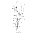
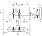
図1を参照して、本実施形態に係る動作補助装置1の構成例について説明する。図1は、動作補助装置1の構成例を示す模式図である。本実施形態に係る動作補助装置1は、ユーザの下半身の動きを補助することで、歩行動作又は階段昇降動作等の左右の脚の運動を補助するための装置であり、いわゆる外骨格ロボットとも呼ばれる。動作補助装置1は、ユーザの人体に装着される装着具10と、能動関節を回転駆動させるアクチュエータ20とを備える。
(Configuration example of motion assist device)
With reference to FIG. 1, the structural example of the
本実施形態に係る動作補助装置1の概略を説明すると、装着具10は、左右の脚のそれぞれに対応して、腰部アーム部材31と、大腿部アーム部材33と、下腿部アーム部材35とを備える。腰部アーム部材31の下端と大腿部アーム部材33の上端とは、第1の腰部関節部30及び第2の腰部関節部90を介して連結されている。第1の腰部関節部30は、人体の腰関節の曲げ伸ばし動作に対応して腰部アーム部材31と大腿部アーム部材33とを相対回転可能に連結する。つまり、第1の腰部関節部30は、腰部アーム部材31及び大腿部アーム部材33を人体の前後方向に沿って相対的に回動可能にする。また、第2の腰部関節部90は、人体の腰関節の内転動作及び外転動作に対応して腰部アーム部材31及び大腿部アーム部材33を相対回転可能に連結する。つまり、第2の腰部関節部90は、腰部アーム部材31及び大腿部アーム部材33を人体の側方へと相対的に回動可能にする。
The outline of the
また、大腿部アーム部材33の下端部にはスライド機構150を介して大腿部装着部37が連結されている。スライド機構150は、大腿部アーム部材33と大腿部装着部37とを人体の大腿部の長さ方向へ相対的にスライド可能に連結する。大腿部装着部37には、人体の大腿部に沿って下方に延びる支持部材44が連結されている。支持部材44には、膝部関節部40を介して下腿部アーム部材35が相対回転可能に連結されている。かかる下腿部アーム部材35は、上方側下腿部装着部41及び下方側下腿部装着部42により人体の下腿部に対して固定されている。
A
本実施形態に係る動作補助装置1をより詳細に説明すると、装着具10のうち、腰部アーム部材31、大腿部アーム部材33、支持部材44、及び下腿部アーム部材35は、例えば、樹脂材料により成形された成形体であり、所定程度の剛性を有し、かつ、軽量化が実現されている。したがって、腰部アーム部材31、大腿部アーム部材33、支持部材44、及び下腿部アーム部材35は、曲げや割れに対する耐性を有する。
The
腰部アーム部材31は、人体の腰部に装着される腰部装着部15に連結されている。腰部アーム部材31と腰部装着部15とは一体的に形成されていてもよく、あるいは、連結治具等を用いて連結されていてもよい。腰部装着部15は、本発明における第1の装着部に相当する。腰部装着部15は、例えば、人体の背中側に配置されて、下方側腰部固定ベルト13及び上方側腰部固定ベルト14を用いて腰部に固定される。下方側腰部固定ベルト13は、例えば、人体の腰部の下方側に巻き付けられて、バックル又は面ファスナー等の図示しない固定具等を用いて腰部に固定される。上方腰部固定ベルト14は、例えば、人体の腰部の上方側に巻き付けられて、図示しない固定具等を用いて腰部に固定される。なお、腰部装着部15及び腰部固定ベルトの構成は上記の例に限られない。腰部装着部15が肩ベルト等により固定されてもよい。
The
腰部装着部15には、アクチュエータ20や図示しないバッテリユニット、CPU(Central Processing Unit)等のプロセッサを備えた制御装置等が収容されるケース5が連結される。制御装置がバッテリユニットからの供給電流を制御することによって、アクチュエータ20が駆動される。アクチュエータ20は、例えば、回転式のロータリモータであってもよく、直線運動を回転運動に変換するギヤ機構とリニアモータとの組み合わせであってもよい。また、アクチュエータ20は、減速機を備えてもよい。
The
かかるアクチュエータ20には、図示しないワイヤ等の可撓性の動力伝達部材が接続され、アクチュエータ20の駆動によって、離れた位置にある第1の腰部関節部30、及び膝部関節部40が回転駆動される。第2の腰部関節部90についてもアクチュエータ20によって駆動される能動関節であってもよい。図2には1つのアクチュエータ20が図示されているが、駆動される関節部(能動関節)の数と同数のアクチュエータ20が備えられる。アクチュエータ20は、可撓性の動力伝達部材としての図示しないワイヤ等を巻取り、あるいは、送出することで、腰部アーム部材31と大腿部アーム部材33、あるいは、大腿部アーム部材33と下腿部アーム部材35とを相対的に回転駆動させる。
A flexible power transmission member such as a wire (not shown) is connected to the
ワイヤとしては、例えば、ボーデンケーブルが用いられる。ボーデンケーブルが用いられる場合、腰部アーム部材31、大腿部アーム部材33、又は支持部材44等にボーデンケーブルを固定させつつ、内部のワイヤを進退させることができる。また、ボーデンケーブルが用いられる場合、ボーデンケーブルが外部に露出した状態であっても、ユーザ等の安全性を確保することができる。なお、可撓性の動力伝達部材は、ベルト又はチェーン等に例示される他の可撓性の部材であってもよい。
For example, a Bowden cable is used as the wire. When the Bowden cable is used, the internal wire can be advanced and retracted while fixing the Bowden cable to the
また、動作補助装置1は、ユーザの筋電位信号を検出するための図示しない筋電位センサを有してもよい。筋電位センサは、例えば、人体の大腿部の表面に配置された表面筋電位検出電極(表面電極)を含んでもよい。筋電位センサは、動作補助装置1により補助される動作を行わせる筋力に対応する運動単位(筋肉)に応じてあらかじめ位置が決定されて配置される。なお、表面電極の数は1個であってもよいし、複数個であってもよい。
Moreover, the
例えば、本実施形態に係る動作補助装置1は、主としてユーザの脚の前後運動(歩行動作)を補助する装置であるため、これらの筋電位センサの表面電極は、例えば、人体の大腿四頭筋の筋電位を検出可能な位置に配置されてもよい。このとき、筋電位センサの電極は、近接して配置された2つの電極を含んでもよい。さらには、筋電位センサの電極は、運動単位の筋線維の方向に沿って配列されてもよい。これにより、同じ筋線維の筋電位が検出されやすくなり、2つの検出値の差分を求めてノイズを低減させることができる。
For example, since the
筋電位センサとしては、例えば、静電容量型のセンサが用いられる。静電容量型の筋電位センサでは、検出される筋電位に応じて静電容量が変化し、当該静電容量の変化が電気信号に変換されて出力される。静電容量型の筋電位センサであれば、皮膚の表面に直接接触させることなく、所望の筋肉の筋電位を検出することができる。静電容量型の筋電位センサが用いられる場合、筋電位センサは、例えば、電極部、発振回路及び出力回路を備える。また、筋電位センサは、AD変換器及び増幅器を備えてもよい。また、筋電位センサは、AD変換器及び増幅器を備えてもよい。筋電位センサの電極部は、例えば、単極型、双極型又は三極型の電極であってよく、さらに、アレイ型又はマトリックス型の電極であってもよい。 As the myoelectric potential sensor, for example, a capacitance type sensor is used. In the electrostatic capacitance type myoelectric potential sensor, the electrostatic capacitance changes in accordance with the detected myoelectric potential, and the change in the electrostatic capacitance is converted into an electrical signal and output. If it is a capacitance type myoelectric potential sensor, the myoelectric potential of a desired muscle can be detected without directly contacting the surface of the skin. When an electrostatic capacitance type myoelectric potential sensor is used, the myoelectric potential sensor includes, for example, an electrode unit, an oscillation circuit, and an output circuit. The myoelectric potential sensor may include an AD converter and an amplifier. The myoelectric potential sensor may include an AD converter and an amplifier. The electrode portion of the myoelectric potential sensor may be, for example, a monopolar, bipolar, or tripolar electrode, and may be an array type or matrix type electrode.
ここで、アクチュエータ20等を収容するケース5の重量を身体の重心に近い位置で支持することができるように、腰部装着部15が人体の背中側に配置され、当該背中側の部分にケース5が配置されることが好ましい。また、装着時においてケース5の位置がふらついて不安定にならないように、腰部装着部15は剛性の高い、硬質の構成要素であることが好ましい。例えば、腰部装着部15は、硬質の樹脂成形品であってもよい。また、アクチュエータ20等が収容されるケース5と腰部装着部15が一体的に形成されていてもよい。
Here, the
腰部装着部15に連結された腰部アーム部材31の下方側は、腰部の側方に位置する部分へと延びている。腰部アーム部材31には、第1の腰部関節部30及び第2の腰部関節部90を介して大腿部アーム部材33が連結されている。第1の腰部関節部30は、人体の腰関節の側方に位置するように設けられる。第2の腰部関節部90は、例えば、第1の腰部関節部30から下方に延びて設けられた中間部材32に連設されている。
The lower side of the
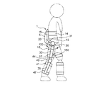
第1の腰部関節部30では、腰部アーム部材31の下端と中間部材32の上端とが相対回転可能に連結されている。例えば、第1の腰部関節部30に設けられた図示しない回転軸部材に対して、中間部材32が回動可能に支持されていてもよい。図2に示したように、第1の腰部関節部30の回転方向は、人体の腰部の曲げ伸ばし動作に対応する腰部アーム部材31と大腿部アーム部材33との相対回転の方向であり、大腿部アーム部材33は人体の前後方向に沿って回動する。
In the 1st waist
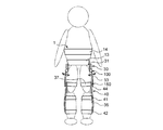
第2の腰部関節部90では、中間部材32の下方側の部分と大腿部アーム部材33の上端とが相対回転可能に連結されている。例えば、中間部材32に設けられた図示しない回転軸部材に対して、大腿部アーム部材35が回動可能に支持されていてもよい。図3に示したように、第2の腰部関節部90の回転方向は、腰関節の内転動作又は外転動作に対応する腰部アーム部材31と大腿部アーム部材33との相対回転の方向であり、大腿部アーム部材33は、人体の側方へと回動する。なお、第2の腰部関節部90は省略されていてもよいが、動作補助装置1が第1の腰部関節部30と併せて第2の腰部関節部90を有することにより、人体の腰関節の動きに対応して動作する動作補助装置1の自由度が高められる。
In the second lumbar joint portion 90, the lower portion of the
大腿部アーム部材33は、第1の腰部関節部30及び第2の腰部関節部90から下方に延びて、大腿部に沿って設けられている。大腿部アーム部材33の長さ方向の中央部には、大腿部装着部37が連結されている。かかる大腿部装着部37は、本発明における第2の装着部に相当する。大腿部装着部37は、人体の脚のうちの大腿部に巻き付けられ、例えば図示しない大腿部固定ベルトを用いて大腿部に固定される。大腿部装着部37は、例えば、人体の大腿部の外形に対応する形状が保持される程度に、所定程度の剛性を有している。大腿部装着部37の形状を人体の大腿部の外形に対応させた場合、大腿部装着部37のうちの少なくとも人体の大腿部に面する部分の形状は、下方側の直径(仮想径)が上方側の直径(仮想径)よりも小さい略円錐形状に構成される。
The
大腿部固定ベルトは、バックル又は面ファスナー等の図示しない連結具を有し、当該連結具を連結させることにより大腿部装着部37が大腿部に固定される。本実施形態に係る動作補助装置1において、大腿部装着部37は、スライド機構150を介して大腿部アーム部材33に連結されている。このため、ユーザの動作に伴って人体の腰関節と膝関節の距離が変化した場合であっても、大腿部アーム部材33に対して大腿部装着部37がスライドすることにより、第1の腰部関節部30、第2の腰部関節部90及び膝部関節部40の位置ずれを抑制することができる。これにより、第1の腰部関節部30、第2の腰部関節部90、及び膝部関節部40の位置が適切な位置に保持されやすくなる。
The thigh fixing belt has a connecting tool (not shown) such as a buckle or a hook-and-loop fastener, and the
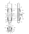
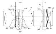
ここで、図4〜図6を参照して、スライド機構150の構成の一例を説明する。図4は、大腿部アーム部材33の裏側(大腿部に面する側)の平面図、I−I断面矢視図及びII−II断面矢視図を示す。図5は、大腿部装着部37の表側(大腿部に面する側の反対側)の平面図、III−III断面矢視図及びIV−IV断面矢視図を示す。図6は、大腿部装着部37を大腿部アーム部材33に接続した状態を表側から見た平面図、及び、側方から見た側面図を示す。
Here, an example of the configuration of the
図4に示すように、大腿部アーム部材33は、ガイドレール141と、可動部143と、第1の付勢部材151a,151bと、第2の付勢部材153a,153bとを備える。ガイドレール141は、両側面にレール溝142を有し、例えば固定ネジ等により大腿部アーム部材33に固定されている。ガイドレール141は、動作補助装置1をユーザが装着した状態で、大腿部の長さ方向に沿って配置される。可動部143は、大腿部側に突出する固定軸部154を有する。かかる固定軸部154には、大腿部装着部37に設けられた接続部材161が取り付けられる。
As shown in FIG. 4, the
可動部143は、ガイドレール141のレール溝142に係合する係止突部144を有し、ガイドレール141から脱離しないようにして、ガイドレール141上を移動可能になっている。したがって、可動部143は、大腿部の長さ方向に沿ってスライド可能になっている。かかるガイドレール141及び可動部143が、スライド機構150を構成する。ガイドレール141及び可動部143は、例えば、アルミニウム等の金属材料により構成されてもよい。
The
大腿部アーム部材33は、ガイドレール141の両端に対応する位置にリブ147,149を有する。かかるリブ147,149は、ガイドレール141上を移動する可動部143のスライド範囲を規制する。また、一方のリブ147には、第1の付勢部材151a,151bの端部が固定され、他方のリブ149には、第2の付勢部材153a,153bの端部が固定される。第1の付勢部材151a,151b及び第2の付勢部材153a,153bの他端は、大腿部装着部37に設けられた接続部材161に固定される。つまり、第1の付勢部材151a,151b及び第2の付勢部材153a,153bは、一の部分が、ガイドレール141が設けられた大腿部アーム部材33側に固定され、他の部分が可動部143とともにスライドする大腿部装着部37側に固定される。大腿部アーム部材33と大腿部装着部37とは相対回転する部材である。例えば、第1の付勢部材151a,151b及び第2の付勢部材153a,153bとしては、引張コイルばねが用いられ得る。
The
図5に示すように、接続部材161は、大腿部装着部37における大腿部側とは反対側の面に、例えば、固定ネジ165a,165bにより固定されている。接続部材161は、可動部143の固定軸部154を受容する孔部163を有し、固定軸部154が孔部163に嵌入されることにより、大腿部装着部37と大腿部アーム部材33とが接続される。固定軸部154の先端部には、弾性ゴム等の弾性体からなる円環部155が設けられ、円環部155を弾性変形させて収縮させつつ固定軸部154を孔部163内に嵌入させることができる。また、固定軸部154の嵌入後には、円環部155が孔部163内で係止され、固定軸部154が接続部材161から抜け落ちにくくなっている。
As shown in FIG. 5, the
固定軸部154が孔部163に嵌入された状態で、大腿部装着部37は、固定軸部154を中心に軸回転可能になっている。つまり、大腿部装着部37は、スライド機構150によるスライド方向に対して直交する方向に延在する固定軸部154の軸回りに自転可能になっている。かかる固定軸部154及び接続部材161が、回転機構を構成する。別の形態として、回転機構は、ボールジョイントを用いて構成されてもよい。
In a state where the fixed
接続部材161における、大腿部装着部37の長手方向の両端側には、第1の付勢部材151a,151b及び第2の付勢部材153a,153bの端部が固定されている。大腿部装着部37の長手方向の一端側に、第1の付勢部材151a及び第2の付勢部材153aの端部が固定され、他端側に、第1の付勢部材151b及び第2の付勢部材153bの端部が固定されている。図示した例では、固定ネジ165a,165bにより、第1の付勢部材151a,151b及び第2の付勢部材153a,153bの端部が接続部材161に固定されている。大腿部装着部37の長手方向は、大腿部の周方向に略一致し、ガイドレール141の配設方向に交差する。
The ends of the
図6に示すように、大腿部装着部37は、スライド機構150及び回転機構を介して大腿部アーム部材33に接続されている結果、固定軸部154を中心に自転可能であるとともに、ガイドレール141に沿ってスライド可能となっている。このとき、両端が、それぞれ大腿部装着部37に設けられた接続部材161と大腿部アーム部材33に設けられたリブ147とに固定された第1の付勢部材151a,151bは、ガイドレール141に沿って大腿部装着部37をリブ147側に引っ張る張力を発生し得る。また、両端が、それぞれ大腿部装着部37に設けられた接続部材161と大腿部アーム部材33に設けられたリブ149とに固定された第2の付勢部材153a,153bは、ガイドレール141に沿って大腿部装着部37をリブ149側に引っ張る張力を発生し得る。
As shown in FIG. 6, the
このため、ユーザの筋力や大腿部装着部37の重量等、大腿部装着部37をスライドさせる負荷が発生していない状態では、4本の第1の付勢部材151a,151b及び第2の付勢部材153a,153bの張力が釣り合う位置に大腿部装着部37が保持される。つまり、スライド機構150によるスライド範囲の中間位置に大腿部装着部37が保持される。このとき、大腿部装着部37は、4本の第1の付勢部材151a,151b及び第2の付勢部材153a,153bの張力が釣り合う姿勢で保持される。
For this reason, in the state where the load which slides the
このため、可動部143がガイドレール141に沿ってリブ147側にスライドした状態では、伸長する第2の付勢部材153a,153bによって可動部143を中間位置に復帰させる張力が生じる。また、可動部143がガイドレール141に沿ってリブ149側にスライドした状態では、伸長する第1の付勢部材151a,151bによって可動部143を中間位置に復帰させる張力が生じる。
For this reason, in a state where the
また、大腿部装着部37が固定軸部154を中心に時計回りに自転した状態では、対角に配置された伸長する第1の付勢部材151a及び第2の付勢部材153bによって大腿部装着部37を初期姿勢に復帰させる張力が生じる。また、大腿部装着部37が固定軸部154を中心に反時計回りに自転した状態では、対角に配置された伸長する第1の付勢部材151b及び第2の付勢部材153aによって大腿部装着部37を初期姿勢に復帰させる張力が生じる。
Further, in a state where the
第1の付勢部材151a,151b及び第2の付勢部材153a,153bにより生じ得る張力は、大腿部装着部37を中間位置あるいは初期姿勢に復帰させ得る張力であれば足り、大腿部装着部37をスライドさせるためにユーザに大きな負荷がかからないようにされる。
The tension that can be generated by the
なお、上記のスライド機構150は一例であって、スライド機構の構成はかかる例に限定されない。スライド機構は、第1の腰部関節部30又は第2の腰部関節部90と、大腿部装着部37、ひいては、膝部関節部40との距離を可変にし得るものであれば、他の構成であってもよい。例えば、上記のスライド機構150は、大腿部アーム部材33側にガイドレール141を有していたが、大腿部装着部37側にガイドレールを有する構成であってもよい。
The
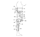
図1に戻り、大腿部装着部37には、人体の大腿部の長さ方向に沿って下方に延びる支持部材44が連結されている。かかる支持部材44は、上端側が大腿部装着部37に固定され、下端側が膝部関節部40を介して下腿部アーム部材35に連結されている。膝部関節部40は、人体の膝関節の側方に位置するように設けられている。膝部関節部40では、支持部材44の下端と下腿部アーム部材35の上端とが相対回転可能に連結されている。例えば、膝部関節部40に設けられた図示しない回転軸部材に対して、下腿部アーム部材35が回動可能に支持されていてもよい。
Returning to FIG. 1, the
下腿部アーム部材35は、膝部関節部40から下方に延びて、下腿部に沿って設けられている。下腿部アーム部材35の上部には上方側下腿部装着部41が連結され、下腿部アーム部材35の下部には下方側下腿部装着部42が連結されている。上方側下腿部装着部41は、少なくとも人体の腓腹部(ふくらはぎ)の最も太い部分よりも上方に装着される。かかる上方側下腿部装着部41の装着位置では、下腿部の太さが下方に向かって拡大している。一方、下方側下腿部装着部42は、少なくとも人体の腓腹部(ふくらはぎ)の最も太い部分よりも下方に装着される。上方側下腿部装着部41及び下方側下腿部装着部42は、人体の脚のうちの下腿部に巻き付けられ、図示しない下腿部固定ベルトを用いて下腿部に固定される。例えば、下腿部固定ベルトはバックル又は面ファスナー等の図示しない連結具を有し、連結具を連結させることにより下腿部アーム部材35が下腿部に固定される。なお、上方側下腿部装着部41及び下方側下腿部装着部42が固定ベルトであってもよい。
The
上方側下腿部装着部41及び下方側下腿部装着部42は、それぞれ人体の下腿部に装着された状態では、少なくとも人体の下腿部に面する部分の形状が、装着位置における下腿部の外形に対応する形状とされる。例えば、当該形状に保たれる所定の剛性を有する部材により構成された上方側下腿部装着部41及び下方側下腿部装着部42が、固定ベルト等を用いて下腿部に固定されてもよい。あるいは、ベルト状の上方側下腿部装着部41及び下方側下腿部装着部42が下腿部に巻き付けられることによって、下腿部の外形に対応する形状を成してもよい。つまり、人体の下腿部に装着された状態において、上方側下腿部装着部41は、上方側の直径(仮想径)が下方側の直径(仮想径)よりも小さい略円錐形状に構成され、下方側への位置ずれが生じにくくなっている。また、下方側下腿部装着部42は、下方側の直径(仮想径)が上方側の直径(仮想径)よりも小さい略円錐形状に構成され、上方側への位置ずれが生じにくくなっている。
In the state where the upper
上述のとおり、膝部関節部40により互いに連結された下腿部アーム部材35及び支持部材44は、所定の剛性を有する樹脂成形品等により構成されており、下腿部アーム部材35及び支持部材44によって大腿部装着部37が支持され得る。このため、図7に点線で示したように、上方側下腿部装着部41及び下方側下腿部装着部42により下腿部アーム部材35の上下方向への位置ずれを抑制することによって、膝部関節部40及び大腿部装着部37の上下方向の位置ずれが抑制される。つまり、膝部関節部40により連結された支持部材44及び下腿部アーム部材35は、上方側下腿部装着部41によって下方側への位置ずれが抑制され、かつ、大腿部装着部37及び下方側下腿部装着部42によって上方側への位置ずれが抑制される。したがって、大腿部装着部37がスライド機構150を介して大腿部アーム部材33に連結され、大腿部装着部37が大腿部アーム部材33に対してスライドし得るとしても、大腿部装着部37の位置ずれが抑制される。これにより、膝部関節部40の位置が人体の膝関節の側方から大きくずれることが抑制される。
As described above, the
また、大腿部アーム部材33と大腿部装着部37とはスライド機構150を介して連結されていることから、大腿部装着部37よりも下方の膝部関節部40及び下腿部アーム部材35等の構成部分の重量のうち、上方側腰部固定ベルト14及び下方側腰部固定ベルト13によって支持される重量が低減される。つまり、図7に破線で示したように、上方側腰部固定ベルト14及び下方側腰部固定ベルト13は、主としてスライド機構150よりも上側の構成部分の重量を担うことになって、上方側腰部固定ベルト14及び下方側腰部固定ベルト13が担う重量が低減される。したがって、腰部アーム部材31、第1の腰部関節部30、第2の腰部関節部90、及び大腿部アーム部材33が安定的に支持される。これにより、第1の腰部関節部30及び第2の腰部関節部90の位置が、人体の腰関節の側方から大きくずれることが抑制される。
Further, since the
以上説明したように、本実施形態にかかる動作補助装置1においては、大腿部アーム部材33と大腿部装着部37とがスライド機構150を介して連結されている。かかる大腿部装着部37は、上方側下腿部装着部41及び下方側下腿部装着部42により上下方向の位置ずれが抑制された下腿部アーム部材35、膝部関節部40、及び支持部材44によって、上下方向への位置ずれが抑制されている。特に、下腿部アーム部材35を下腿部に固定する上方側下腿部装着部41は、下方側への位置ずれを生じにくい構成要素であることから、大腿部装着部37が下方に位置ずれしやすい形状を有するにもかかわらず、大腿部装着部37の下方への位置ずれが抑制される。
As described above, in the
(変形例)
ここまで、本実施形態に係る動作補助装置1の構成例を説明したが、動作補助装置1は種々の変形が可能である。以下、本実施形態に係る動作補助装置1の一変形例を説明する。
(Modification)
So far, the configuration example of the
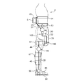
図8は、変形例に係る動作補助装置2の構成例を示す模式図である。変形例に係る動作補助装置2においては、下腿部アーム部材35の下端に、足関節部50を介して、人体の足裏に配置されて足底部が載置される足台部60が連結されている。足台部60は、人体の足先が挿入される甲押え部63を有する。足関節部50は、人体の足関節(踝)の側方に位置するように設けられ、下腿部アーム部材35の下端と足台部60とを相対回転可能に連結する。足台部60は、人体の足関節の曲げ伸ばし動作に対応して、足関節部50を中心に回動可能に構成されている。かかる足台部60は、直接あるいは靴底を介して接地した状態で、動作補助装置1の重量を支持する機能を有している。また、足関節部50が能動関節として構成される場合、足台部60は、足関節の曲げ伸ばし動作を補助する際の可動部としての機能も有する。足台部60は、硬質の樹脂成形品あるいは金属プレート等により構成される。これ以外の構成要素は、上記の実施形態に係る動作補助装置1と同様に構成することができる。
FIG. 8 is a schematic diagram illustrating a configuration example of the motion assisting device 2 according to the modification. In the motion assisting device 2 according to the modified example, a
このため、変形例に係る動作補助装置2では、少なくとも大腿部装着部37よりも下方の支持部材44、膝部関節部40、及び下腿部アーム部材35の重量の一部を、足台部60を介して地面に伝達させることができる。つまり、足台部60は、下腿部アーム部材35を介して伝達される重量を下方から支持することができる。したがって、変形例に係る動作補助装置2は、上方側下腿部装着部41と併せて足台部60によって下腿部アーム部材35の上下方向の位置ずれを抑制することができる。これにより、大腿部装着部37及び膝部関節部40の上下方向の位置ずれが抑制される。また、これに伴って、下方側腰部固定ベルト13及び上方側腰部固定ベルト14が担う動作補助装置2の重量が小さくなって、第1の腰部関節部30及び第2の腰部関節部90の位置が大きくずれることが抑制される。
Therefore, in the motion assisting device 2 according to the modified example, at least a part of the weight of the
特に、足台部60は、地面に接地可能な部分であることから、動作補助装置2によれば、足関節部50及び下腿部アーム部材35を介して、膝部関節部40及び支持部材44の重量を担う確実性が高められる。したがって、動作補助装置2によっても、第1の腰部関節部30、第2の腰部関節部90、及び膝部関節部40の位置ずれを抑制する確実性を高めることができる。
In particular, since the
以上、添付図面を参照しながら本発明の好適な実施形態について詳細に説明したが、本発明はかかる例に限定されない。本発明の属する技術の分野における通常の知識を有する者であれば、特許請求の範囲に記載された技術的思想の範疇内において、各種の変更例または修正例に想到し得ることは明らかであり、これらについても、当然に本発明の技術的範囲に属するものと了解される。 The preferred embodiments of the present invention have been described in detail above with reference to the accompanying drawings, but the present invention is not limited to such examples. It is obvious that a person having ordinary knowledge in the technical field to which the present invention pertains can come up with various changes or modifications within the scope of the technical idea described in the claims. Of course, it is understood that these also belong to the technical scope of the present invention.
例えば、上記実施形態では、動作補助装置が、ユーザの両脚の前後運動を補助する装置として構成されていたが、本発明はかかる例に限定されない。例えば、動作補助装置は、ユーザの片脚の前後運動を補助する装置であってもよい。この場合、第1の腰部関節部、第2の腰部関節部、膝部関節部、足関節部、腰部アーム部材、大腿部アーム部材、下腿部アーム部材、大腿部装着部、下腿部装着部、及び足台部は、左右のいずれか一方にのみ設けられる。 For example, in the above-described embodiment, the motion assist device is configured as a device that assists the user's back and forth motion of both legs, but the present invention is not limited to such an example. For example, the motion assisting device may be a device that assists the user's one leg back and forth movement. In this case, the first lumbar joint, the second lumbar joint, the knee joint, the ankle joint, the lumbar arm member, the thigh arm member, the crus arm member, the thigh attachment part, the crus The part mounting part and the footrest part are provided only on either the left or right side.
また、上記実施形態では、人体の下腿部のうち、下方に向かって太さが拡大する部位に装着される下腿部装着部(上方側下腿部装着部)41は、腓腹部の最も太い部分よりも上方に装着されていたが、本発明はかかる例に限定されない。例えば、下腿部アーム部35に連結された下腿部装着部が、人体の足関節の上方に装着されてもよい。足関節の上方の部位も下方に向かって太さが拡大しているため、かかる下腿部装着部であっても、下腿部アーム部35の下方への位置ずれが抑制される。
In the above embodiment, the crus attachment part (upper crus attachment part) 41 that is attached to a part of the human lower leg that increases in thickness downward is the most in the calf part. Although it was mounted above the thick portion, the present invention is not limited to such an example. For example, the crus attachment part connected to the
1 動作補助装置
13 下方側腰部固定ベルト
14 上方側腰部固定ベルト
15 腰部装着部
30 第1の腰部関節部
31 腰部アーム部材
32 中間部材
33 大腿部アーム部材
35 下腿部アーム部材
37 大腿部装着部
40 膝部関節部
41 上方側下腿部装着部
42 下方側下腿部装着部
44 支持部材
DESCRIPTION OF
Claims (5)
前記腰部アーム部材に連結されて人体の腰部に装着される第1の装着部と、
人体の大腿部に装着される第2の装着部と、
前記大腿部アーム部材及び前記第2の装着部を、前記大腿部の長さ方向へ相対的にスライド可能に連結するスライド機構と、
前記第2の装着部に連結されて前記大腿部に沿って下方に延びる支持部材と、
人体の膝関節の側方に位置し、人体の下腿部に沿って延びる下腿部アーム部材及び前記支持部材を相対回転可能に連結する膝部関節部と、
前記下腿部アーム部材に連結され、前記下腿部のうち、下方に向かって太さが拡大する部位に装着される下腿部装着部と、
を備える、動作補助装置。 A lumbar joint that is located to the side of the hip joint of the human body and connects the lumbar arm member and the thigh arm member in a relatively rotatable manner;
A first attachment portion connected to the waist arm member and attached to the waist of a human body;
A second attachment portion attached to the thigh of the human body;
A slide mechanism that connects the thigh arm member and the second mounting portion so as to be relatively slidable in the length direction of the thigh;
A support member connected to the second mounting portion and extending downward along the thigh;
A knee joint part that is located on the side of the knee joint of the human body and that extends along the lower leg part of the human body and that connects the support member in a relatively rotatable manner;
A crus attachment part that is connected to the crus arm member and is attached to a portion of the crus that increases in thickness downward.
A motion assisting device.
人体の足関節の側方に位置し、前記足台部及び前記下腿部アーム部材を相対回転可能に連結する足関節部と、
をさらに備える、請求項1又は2に記載の動作補助装置。 A footrest on which the sole of the human body is placed;
An ankle joint located on the side of the ankle joint of the human body and connecting the footrest and the crus arm member in a relatively rotatable manner;
The operation assisting device according to claim 1, further comprising:
さらに、前記腰関節の内転及び外転に対応して前記腰部アーム部材及び前記大腿部アーム部材を相対回転可能に連結する第2の腰部関節部を備える、請求項1〜3のいずれか1項に記載の動作補助装置。 The lumbar joint part is a first lumbar joint part that couples the lumbar arm member and the thigh arm member so as to be capable of relative rotation in response to a bending and stretching operation of the lumbar joint,
Furthermore, the 2nd waist joint part which connects the said waist arm member and the said thigh arm member so that relative rotation is possible corresponding to the inversion and the abduction of the said waist joint, It is any one of Claims 1-3. The motion auxiliary device according to Item 1.
The motion auxiliary device according to claim 1, further comprising a ball joint that connects the thigh arm member and the second mounting portion.
Priority Applications (1)
| Application Number | Priority Date | Filing Date | Title |
|---|---|---|---|
| JP2016238344A JP2018094635A (en) | 2016-12-08 | 2016-12-08 | Motion assisting device |
Applications Claiming Priority (1)
| Application Number | Priority Date | Filing Date | Title |
|---|---|---|---|
| JP2016238344A JP2018094635A (en) | 2016-12-08 | 2016-12-08 | Motion assisting device |
Publications (1)
| Publication Number | Publication Date |
|---|---|
| JP2018094635A true JP2018094635A (en) | 2018-06-21 |
Family
ID=62634139
Family Applications (1)
| Application Number | Title | Priority Date | Filing Date |
|---|---|---|---|
| JP2016238344A Pending JP2018094635A (en) | 2016-12-08 | 2016-12-08 | Motion assisting device |
Country Status (1)
| Country | Link |
|---|---|
| JP (1) | JP2018094635A (en) |
Cited By (6)
| Publication number | Priority date | Publication date | Assignee | Title |
|---|---|---|---|---|
| CN109730902A (en) * | 2019-01-04 | 2019-05-10 | 电子科技大学 | A hip joint adjustable binding for lower limb exoskeleton robot |
| CN113195175A (en) * | 2018-12-17 | 2021-07-30 | 本田技研工业株式会社 | Auxiliary device for flexion and extension movements |
| CN113580100A (en) * | 2021-06-28 | 2021-11-02 | 北京机械设备研究所 | Passive type load-bearing maneuvering exoskeleton |
| CN113978771A (en) * | 2021-10-28 | 2022-01-28 | 哈尔滨工业大学 | Body limiting device |
| IT202100015641A1 (en) * | 2021-06-15 | 2022-12-15 | Fondazione St Italiano Tecnologia | Knee motion assist device |
| CN119408628A (en) * | 2024-12-02 | 2025-02-11 | 哈尔滨工业大学 | Wheel-foot leg and wheel-foot robot with double buffer structure |
-
2016
- 2016-12-08 JP JP2016238344A patent/JP2018094635A/en active Pending
Cited By (9)
| Publication number | Priority date | Publication date | Assignee | Title |
|---|---|---|---|---|
| CN113195175A (en) * | 2018-12-17 | 2021-07-30 | 本田技研工业株式会社 | Auxiliary device for flexion and extension movements |
| CN109730902A (en) * | 2019-01-04 | 2019-05-10 | 电子科技大学 | A hip joint adjustable binding for lower limb exoskeleton robot |
| CN109730902B (en) * | 2019-01-04 | 2021-06-08 | 电子科技大学 | A hip joint adjustable binding for lower limb exoskeleton robot |
| IT202100015641A1 (en) * | 2021-06-15 | 2022-12-15 | Fondazione St Italiano Tecnologia | Knee motion assist device |
| WO2022263958A1 (en) * | 2021-06-15 | 2022-12-22 | Fondazione Istituto Italiano Di Tecnologia | A knee movement assistive device |
| CN113580100A (en) * | 2021-06-28 | 2021-11-02 | 北京机械设备研究所 | Passive type load-bearing maneuvering exoskeleton |
| CN113580100B (en) * | 2021-06-28 | 2023-10-27 | 北京机械设备研究所 | Passive load-bearing motorized exoskeleton |
| CN113978771A (en) * | 2021-10-28 | 2022-01-28 | 哈尔滨工业大学 | Body limiting device |
| CN119408628A (en) * | 2024-12-02 | 2025-02-11 | 哈尔滨工业大学 | Wheel-foot leg and wheel-foot robot with double buffer structure |
Similar Documents
| Publication | Publication Date | Title |
|---|---|---|
| JP2018094635A (en) | Motion assisting device | |
| CN107106399B (en) | Exercise assist device | |
| US10799381B2 (en) | Tendon device for suit type robot for assisting human with physical strength | |
| JP2019188161A (en) | Controllable inactive artificial knee | |
| JP5876550B1 (en) | Joint motion assist device | |
| JP5313609B2 (en) | Frame structure of wearable motion assist device. | |
| KR102158131B1 (en) | Walking assist apparatus | |
| JP5878660B1 (en) | Wearable motion assist device | |
| JP2018164694A (en) | Limb motion support apparatus | |
| CN112775932A (en) | Ankle assisting exoskeleton device | |
| JP2014104185A (en) | Exercise assistance device and exercise assistance method | |
| CN114980842A (en) | joint movement aids | |
| US8968223B2 (en) | Motion assist device | |
| JP5326391B2 (en) | Walking assist device | |
| KR102786910B1 (en) | Motion assist apparatus | |
| JP2018099767A (en) | Motion assist device | |
| KR102663308B1 (en) | Motion assist apparatus comprising link having lock notification function | |
| JP2018030183A (en) | Movement assisting device | |
| JP6315031B2 (en) | Exercise support device and exercise support method | |
| KR20190079986A (en) | Walking Assistance Apparatus and Walking Assistance Method | |
| JP2018122364A (en) | Motion assistance device, control device of motion assistance device and control method of motion assistance device | |
| JP5598667B2 (en) | Walking assistance device, walking assistance method, walking assistance program, etc. | |
| JP2018187083A (en) | Lower limb orthosis power assist device and lower limb orthosis | |
| KR102935827B1 (en) | Gait supporting device using cable customized for gait patient | |
| KR102935747B1 (en) | Active gait supporting device using anterior and posterior motors |