EP4355283B1 - Vorrichtung zur unterstützung der kniebewegung - Google Patents
Vorrichtung zur unterstützung der kniebewegung Download PDFInfo
- Publication number
- EP4355283B1 EP4355283B1 EP22728980.8A EP22728980A EP4355283B1 EP 4355283 B1 EP4355283 B1 EP 4355283B1 EP 22728980 A EP22728980 A EP 22728980A EP 4355283 B1 EP4355283 B1 EP 4355283B1
- Authority
- EP
- European Patent Office
- Prior art keywords
- gear
- driver
- configuration
- garment
- assistive device
- Prior art date
- Legal status (The legal status is an assumption and is not a legal conclusion. Google has not performed a legal analysis and makes no representation as to the accuracy of the status listed.)
- Active
Links
Images







Classifications
-
- A—HUMAN NECESSITIES
- A61—MEDICAL OR VETERINARY SCIENCE; HYGIENE
- A61H—PHYSICAL THERAPY APPARATUS, e.g. DEVICES FOR LOCATING OR STIMULATING REFLEX POINTS IN THE BODY; ARTIFICIAL RESPIRATION; MASSAGE; BATHING DEVICES FOR SPECIAL THERAPEUTIC OR HYGIENIC PURPOSES OR SPECIFIC PARTS OF THE BODY
- A61H3/00—Appliances for aiding patients or disabled persons to walk about
-
- A—HUMAN NECESSITIES
- A61—MEDICAL OR VETERINARY SCIENCE; HYGIENE
- A61H—PHYSICAL THERAPY APPARATUS, e.g. DEVICES FOR LOCATING OR STIMULATING REFLEX POINTS IN THE BODY; ARTIFICIAL RESPIRATION; MASSAGE; BATHING DEVICES FOR SPECIAL THERAPEUTIC OR HYGIENIC PURPOSES OR SPECIFIC PARTS OF THE BODY
- A61H1/00—Apparatus for passive exercising; Vibrating apparatus; Chiropractic devices, e.g. body impacting devices, external devices for briefly extending or aligning unbroken bones
- A61H1/02—Stretching or bending or torsioning apparatus for exercising
- A61H1/0237—Stretching or bending or torsioning apparatus for exercising for the lower limbs
- A61H1/024—Knee
-
- A—HUMAN NECESSITIES
- A61—MEDICAL OR VETERINARY SCIENCE; HYGIENE
- A61H—PHYSICAL THERAPY APPARATUS, e.g. DEVICES FOR LOCATING OR STIMULATING REFLEX POINTS IN THE BODY; ARTIFICIAL RESPIRATION; MASSAGE; BATHING DEVICES FOR SPECIAL THERAPEUTIC OR HYGIENIC PURPOSES OR SPECIFIC PARTS OF THE BODY
- A61H1/00—Apparatus for passive exercising; Vibrating apparatus; Chiropractic devices, e.g. body impacting devices, external devices for briefly extending or aligning unbroken bones
- A61H1/02—Stretching or bending or torsioning apparatus for exercising
- A61H1/0237—Stretching or bending or torsioning apparatus for exercising for the lower limbs
- A61H1/0255—Both knee and hip of a patient, e.g. in supine or sitting position, the feet being moved together in a plane substantially parallel to the body-symmetrical plane
-
- A—HUMAN NECESSITIES
- A61—MEDICAL OR VETERINARY SCIENCE; HYGIENE
- A61H—PHYSICAL THERAPY APPARATUS, e.g. DEVICES FOR LOCATING OR STIMULATING REFLEX POINTS IN THE BODY; ARTIFICIAL RESPIRATION; MASSAGE; BATHING DEVICES FOR SPECIAL THERAPEUTIC OR HYGIENIC PURPOSES OR SPECIFIC PARTS OF THE BODY
- A61H3/00—Appliances for aiding patients or disabled persons to walk about
- A61H2003/007—Appliances for aiding patients or disabled persons to walk about secured to the patient, e.g. with belts
-
- A—HUMAN NECESSITIES
- A61—MEDICAL OR VETERINARY SCIENCE; HYGIENE
- A61H—PHYSICAL THERAPY APPARATUS, e.g. DEVICES FOR LOCATING OR STIMULATING REFLEX POINTS IN THE BODY; ARTIFICIAL RESPIRATION; MASSAGE; BATHING DEVICES FOR SPECIAL THERAPEUTIC OR HYGIENIC PURPOSES OR SPECIFIC PARTS OF THE BODY
- A61H2201/00—Characteristics of apparatus not provided for in the preceding codes
- A61H2201/12—Driving means
- A61H2201/1207—Driving means with electric or magnetic drive
- A61H2201/1215—Rotary drive
-
- A—HUMAN NECESSITIES
- A61—MEDICAL OR VETERINARY SCIENCE; HYGIENE
- A61H—PHYSICAL THERAPY APPARATUS, e.g. DEVICES FOR LOCATING OR STIMULATING REFLEX POINTS IN THE BODY; ARTIFICIAL RESPIRATION; MASSAGE; BATHING DEVICES FOR SPECIAL THERAPEUTIC OR HYGIENIC PURPOSES OR SPECIFIC PARTS OF THE BODY
- A61H2201/00—Characteristics of apparatus not provided for in the preceding codes
- A61H2201/12—Driving means
- A61H2201/1253—Driving means driven by a human being, e.g. hand driven
- A61H2201/1261—Driving means driven by a human being, e.g. hand driven combined with active exercising of the patient
-
- A—HUMAN NECESSITIES
- A61—MEDICAL OR VETERINARY SCIENCE; HYGIENE
- A61H—PHYSICAL THERAPY APPARATUS, e.g. DEVICES FOR LOCATING OR STIMULATING REFLEX POINTS IN THE BODY; ARTIFICIAL RESPIRATION; MASSAGE; BATHING DEVICES FOR SPECIAL THERAPEUTIC OR HYGIENIC PURPOSES OR SPECIFIC PARTS OF THE BODY
- A61H2201/00—Characteristics of apparatus not provided for in the preceding codes
- A61H2201/16—Physical interface with patient
- A61H2201/1602—Physical interface with patient kind of interface, e.g. head rest, knee support or lumbar support
- A61H2201/1628—Pelvis
-
- A—HUMAN NECESSITIES
- A61—MEDICAL OR VETERINARY SCIENCE; HYGIENE
- A61H—PHYSICAL THERAPY APPARATUS, e.g. DEVICES FOR LOCATING OR STIMULATING REFLEX POINTS IN THE BODY; ARTIFICIAL RESPIRATION; MASSAGE; BATHING DEVICES FOR SPECIAL THERAPEUTIC OR HYGIENIC PURPOSES OR SPECIFIC PARTS OF THE BODY
- A61H2201/00—Characteristics of apparatus not provided for in the preceding codes
- A61H2201/16—Physical interface with patient
- A61H2201/1602—Physical interface with patient kind of interface, e.g. head rest, knee support or lumbar support
- A61H2201/1635—Hand or arm, e.g. handle
- A61H2201/1638—Holding means therefor
-
- A—HUMAN NECESSITIES
- A61—MEDICAL OR VETERINARY SCIENCE; HYGIENE
- A61H—PHYSICAL THERAPY APPARATUS, e.g. DEVICES FOR LOCATING OR STIMULATING REFLEX POINTS IN THE BODY; ARTIFICIAL RESPIRATION; MASSAGE; BATHING DEVICES FOR SPECIAL THERAPEUTIC OR HYGIENIC PURPOSES OR SPECIFIC PARTS OF THE BODY
- A61H2201/00—Characteristics of apparatus not provided for in the preceding codes
- A61H2201/16—Physical interface with patient
- A61H2201/1602—Physical interface with patient kind of interface, e.g. head rest, knee support or lumbar support
- A61H2201/164—Feet or leg, e.g. pedal
- A61H2201/1642—Holding means therefor
-
- A—HUMAN NECESSITIES
- A61—MEDICAL OR VETERINARY SCIENCE; HYGIENE
- A61H—PHYSICAL THERAPY APPARATUS, e.g. DEVICES FOR LOCATING OR STIMULATING REFLEX POINTS IN THE BODY; ARTIFICIAL RESPIRATION; MASSAGE; BATHING DEVICES FOR SPECIAL THERAPEUTIC OR HYGIENIC PURPOSES OR SPECIFIC PARTS OF THE BODY
- A61H2201/00—Characteristics of apparatus not provided for in the preceding codes
- A61H2201/16—Physical interface with patient
- A61H2201/1602—Physical interface with patient kind of interface, e.g. head rest, knee support or lumbar support
- A61H2201/165—Wearable interfaces
-
- A—HUMAN NECESSITIES
- A61—MEDICAL OR VETERINARY SCIENCE; HYGIENE
- A61H—PHYSICAL THERAPY APPARATUS, e.g. DEVICES FOR LOCATING OR STIMULATING REFLEX POINTS IN THE BODY; ARTIFICIAL RESPIRATION; MASSAGE; BATHING DEVICES FOR SPECIAL THERAPEUTIC OR HYGIENIC PURPOSES OR SPECIFIC PARTS OF THE BODY
- A61H2201/00—Characteristics of apparatus not provided for in the preceding codes
- A61H2201/50—Control means thereof
- A61H2201/5007—Control means thereof computer controlled
-
- A—HUMAN NECESSITIES
- A61—MEDICAL OR VETERINARY SCIENCE; HYGIENE
- A61H—PHYSICAL THERAPY APPARATUS, e.g. DEVICES FOR LOCATING OR STIMULATING REFLEX POINTS IN THE BODY; ARTIFICIAL RESPIRATION; MASSAGE; BATHING DEVICES FOR SPECIAL THERAPEUTIC OR HYGIENIC PURPOSES OR SPECIFIC PARTS OF THE BODY
- A61H2203/00—Additional characteristics concerning the patient
- A61H2203/04—Position of the patient
- A61H2203/0406—Standing on the feet
-
- A—HUMAN NECESSITIES
- A61—MEDICAL OR VETERINARY SCIENCE; HYGIENE
- A61H—PHYSICAL THERAPY APPARATUS, e.g. DEVICES FOR LOCATING OR STIMULATING REFLEX POINTS IN THE BODY; ARTIFICIAL RESPIRATION; MASSAGE; BATHING DEVICES FOR SPECIAL THERAPEUTIC OR HYGIENIC PURPOSES OR SPECIFIC PARTS OF THE BODY
- A61H2203/00—Additional characteristics concerning the patient
- A61H2203/04—Position of the patient
- A61H2203/0412—Kneeling
Definitions
- the present invention is related to a knee movement assistive device.
- Said assistive device is particularly useful in assisting the knee movement of a user undergoing rehabilitation therapy.
- said assistive device is particularly useful in assisting a user performing a squat.
- XP081027759 discloses a knee exoskeleton comprising a waist garment attachable to a user waist, a calf garment attachable to a user calf, a first gear, a second gear, and an actuator attached to the waist garment and comprising a driver, said driver being configured to switch between an active state, wherein the driver generates a rotational force, and an idle state, wherein the driver generates a null force.
- the knee movement assistive device described does not cause high discomfort in the user wearing said assistive device, reducing the risk of not using the assistive device.
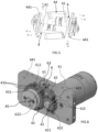
- the locking means 6 are configured to switch between a locking configuration and a releasing configuration.
- the second gear 43 is prevented to rotate around the second rotation center.
- the rotation of the first gear 42 makes the second gear 43 rotate around the second rotation center so that the rotational force generated by the driver 41 is transformed in the tension force and can be transmitted to the calf garment 3 through the transmission cable 5.
- the rotation of the second gear 43 pulls the transmission cable 5 or release the pull action on the transmission cable 5.
- the rotational force of the driver 41 is transformed in a first tension force acting as pull force or in a second tension force acting as a releasing force.
- the second tension force progressively release the first tension force, namely release the pull action transmitted to the calf garment 3.
- the second tension force is opposite to the first tension force.
- the locking means 6 are configured to switch from the locking configuration to the releasing configuration due to the rotation of the first gear 42 when the driver 41 is in the active state. Therefore, when the driver 41 is in the active state, the tension force can be transmitted to the calf garment 3 to assist the user knee movement.
- the locking means 6 are configured to automatically switch from the releasing configuration to the locking configuration when the driver 41 is switched to the idle state. Therefore, when the driver 41 is switched to the idle state, being the locking means 6 in the locking configuration, the tension force generated from the rotational force of the driver 41 is still transmitted to the calf garment 3, without needing to maintain the driver 41 in the active state. In other words, after the desired tension force has been transmitted to the calf garment 3, the driver 41 can be switched to the idle state letting the desired tension force still act on the calf garment 3.
- the driver 41 can be switched to the idle state continuing assisting the user knee movement and reducing, therefore, the overall energy needed to assist the user knee movement with the assistive device 1.
- the second gear 43 has a plurality of second teeth 432 arranged on the second perimetral wall 431.
- the second teeth 432 are equally spaced apart from each other along the second circumferential direction. The rotation of second gear 43 around the second rotation center making the second teeth 432 move along the second circumferential direction.
- the second gear 43 has twenty-five second teeth 432.
- the first gear 42 is configured to clockwise and anticlockwise rotate due to the rotational force generated by the driver 41. It should be noted that, due to the progressively engagement of each first tooth 422 with a respective second tooth 432, the clockwise rotation of the first gear 42 is transformed in an anticlockwise rotation of the second gear 43, while the anticlockwise rotation of the first gear 42 is transformed in a clockwise rotation of the second gear 43. Namely, the rotation direction of the first gear 42 is preferably opposite to the rotation direction of the second gear 43.
- each couple of second teeth 432 is spaced apart by a respective separation distance along the second circumferential direction. Said separation distance is greater than the thickness of each first tooth 422 along the first circumferential direction.
- At least one first tooth 422 is interposed between a couple of second teeth 432 and is spaced apart from each of said second teeth 432 in the locking configuration of the locking means 6.
- the rotational force of the driver 41 makes said first tooth 422 engaging one of said second teeth 432.
- the rotation of the first gear 42 switches the locking means 6 from the locking configuration to the releasing configuration. Namely, the locking means 6 are switched from the locking configuration to the releasing configuration before the first gear 42 makes the second gear 43 to rotate around the second rotation center. In this way, no rotation of the second gear 43 occurs when the locking means 6 are in the locking configuration.
- the locking means 6 comprises a stopper 61 having a first engagement portion 611.
- the first engagement portion 611 has a tip shape.
- the stopper 61 is configured to assume in the locking configuration of the locking means 6 a locking position, wherein the first engagement portion 611 engages at least one second tooth 432.
- the first engagement portion 611 is inserted between a couple of second teeth 432. Therefore, when the stopper 61 is in the locking position the second gear 43 cannot rotate around the second rotation center.
- the stopper 61 is configured to assume in the releasing configuration of the locking means 6 a releasing position, wherein the first engagement portion 611 is spaced apart from the second gear 43 along a direction transverse to the second circumferential direction. It should be noted that, when the locking means 6 are in the releasing configuration the stopper 61 is almost always in the releasing position so that the second gear 43 can rotate around the second rotation center without risking that a second tooth 432 engages the first engagement portion 611. However, it could happen that in the releasing configuration of the locking means 6 a second tooth 432 hits the first engagement portion 611, but without stopping the rotation of the second gear 43.
- the locking means 6 is configured to assume an intermediate configuration between the releasing configuration and the locking configuration.
- said intermediate configuration the engagement portion 611 of the stopper 61 is inserted between a couple of second teeth 432 and is spaced apart from said second teeth 432.
- the passive clockwise rotation of the second gear 43 when the locking means 6 are in the intermediate configuration and the driver 41 is in the idle state makes at least one second tooth 432 engage the first engagement portion of the stopper 611, switching the locking means 6 in the locking configuration, locking the rotation of the second gear 43.
- the locking means 6 comprises a lever 62.
- the lever 62 is configured to rotate around a third rotation center.
- the lever 62 extends between a second engagement portion 621 and an opposite thrust portion 622 along an axis of the lever 62 passing through the third rotation center.
- the thrust portion 622 has a tip shape.
- the thrust portion 622 engages the stopper 61.
- the thrust portion 622 engages a receiving portion 612 of the stopper 61.
- the locking means 6 comprises a spring 63 acting on the stopper 61.
- the spring 63 makes the first engagement portion 611 to progressively engage the second gear 43, when the driver 41 is switched to the idle state.
- the spring 63 always exert a pushing action on the first engagement portion 611 pushing said first engagement portion 611 against the second gear 43.
- the thrust action of the thrust portion 622 acting on the stopper 61 wins the pushing action of the spring 63, displacing the first engagement portion 611 away from the second gear 43.
- the thrust portion 622 stops exerting a thrust action on the stopper 41, so that the pushing action of the spring 63 makes the first engagement portion 611 to progressively engage the second gear 43.
- the thrust portion 622 of the lever 62 remains in contact with the stopper 61 both when the locking means 6 are in the locking configuration and in the releasing configuration, but also during the switching of the locking means 6 between the locking configuration and the releasing configuration.
- the first teeth 422 engages one by one the lever 62 at the second engagement portion 621, making the lever 62 to rotate around the third rotation center.
- the clockwise rotation of the first gear 42 makes the first gear 42 engage the second engagement portion 621 in a first contact area to anticlockwise rotate the lever 62.
- the first teeth 422 engage the second engagement portion 621 in the first contact area.
- the actuator 4 comprises a control unit in signal communication with the driver 41 and with an external device.
- the control unit is configured to switch the driver 41 between the idle state and the working state upon receival of a command signal by the control unit coming from the external device.
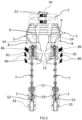
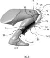
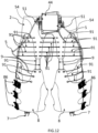
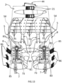
- the thigh garment 8 is attachable to a user thigh, when the user is wearing the assistive device 1, the thigh garment 8 is interposed between the waist garment 2 and the calf garment 3.
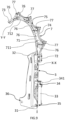
- the assistive device comprises first straps 22 and second straps 23 connecting the waist garment 2 to the thigh garment 8.
- the first straps 22 are arranged on the front side of the user, while the second straps 23 are arranged on the back side of the user.
- Both the first straps 22 and the second straps 23 are arranged in a triangular shape, with one attachment point on the thigh garment 8 and two attachments points on the waist garment 2.
- the first straps 22 defines a first trace A for the load distribution
- the second straps 23 together with the thigh garment 8 defines a second trace B for the load distribution.
- the first 22 and second 23 straps can provide a stable support for the transmission cable 5 and distribute the high tension force to the upper thigh and hip of the user wearing the assistive device 1. For example, if a user wearing the assistive device 1 is performing a squat motion, the load distribution switches between the first trace A and a second trace B.
- the first trace A will deliver the load to the waist garment 2 while the second trace B is loose.
- the first trace A gradually becomes loose and the tension load will deliver to the backside of the waist garment 2 via the second trace B that has the additional benefit of also generating a positive torque around the hip supporting this joint during deep squat and during the transition from a squat to a standing posture.
- an exoskeleton comprising two assistive devices 1 corresponding to the assistive device 1 described above.
- Each assistive device 1 of the exoskeleton is used to assist the movement of a corresponding user knee.
- the actuator 41 of the two assistive devices 1 are arranged in the same box 44.
- the waist garment 2 can be the same for both assistive devices 1 of the exoskeleton.
Landscapes
- Health & Medical Sciences (AREA)
- Epidemiology (AREA)
- Pain & Pain Management (AREA)
- Physical Education & Sports Medicine (AREA)
- Rehabilitation Therapy (AREA)
- Life Sciences & Earth Sciences (AREA)
- Animal Behavior & Ethology (AREA)
- General Health & Medical Sciences (AREA)
- Public Health (AREA)
- Veterinary Medicine (AREA)
- Rehabilitation Tools (AREA)
- Orthopedics, Nursing, And Contraception (AREA)
Claims (10)
- Hilfsvorrichtung der Kniebewegung (1), umfassend:- ein Taillenkleidungsstück (2), das an der Taille eines Benutzers befestigbar ist und ein Wadenkleidungsstück (3), das an der Wade eines Benutzers befestigbar ist, wobei das Wadenkleidungsstück (3) entlang einer Längsrichtung (X-X) angeordnet ist;- einen Aktuator (4), der an dem Taillenkleidungsstück (2) befestigt wird und umfassend einen Treiber (41), wobei der Treiber (41) konfiguriert ist, zwischen einem aktiven Zustand, in dem der Treiber (41) eine Rotationskraft erzeugt, und einem Leerlaufzustand, in dem der Treiber (41) eine Nullkraft erzeugt, umzuschalten, wobei der Aktuator (4) konfiguriert ist, die Rotationskraft des Treibers in eine Spannkraft umzuwandeln;- ein Übertragungskabel (5), das den Aktuator (4) mit dem Wadenkleidungsstück (3) verbindet und konfiguriert ist, die Spannkraft, die durch Umwandeln der Rotationskraft des Treibers (41) erzeugt wird, auf das Wadenkleidungsstück (3) zu übertragen;wobei die Hilfsvorrichtung (1) dadurch konfiguriert ist, dass der Aktuator (4) umfasst:- ein erstes Zahnrad (42), das mit dem Treiber (41) verbunden ist und konfiguriert ist, um ein erstes Rotationszentrum zu drehen, wobei die von dem Treiber (41) erzeugte Rotationskraft bewirkt, dass sich das erste Zahnrad (42) um das erste Rotationszentrum dreht;- ein zweites Zahnrad (43), das mit dem ersten Zahnrad (42) operativ in Eingriff steht und konfiguriert ist, sich um ein zweites Rotationszentrum zu drehen, wobei das Übertragungskabel (5) mit dem zweiten Zahnrad (43) verbunden ist;- Verriegelungsmittel (6), die mit dem ersten (42) und dem zweiten (43) Zahnrad operativ in Eingriff stehen; wobei die Verriegelungsmittel (6) konfiguriert sind, zwischen einer Verriegelungskonfiguration, in der das zweite Zahnrad (43) nicht um das zweite Rotationszentrum drehen kann, und einer Auslösekonfiguration, in der die Rotation des ersten Zahnrads (42) bewirkt, dass sich das zweite Zahnrad (43) um das zweite Rotationszentrum dreht so dass die durch den Treiber (41) erzeugte Rotationskraft in die Spannkraft umgewandelt wird und über das Übertragungskabel (5) auf die Wadenkleidungsstück (3) übertragen werden kann, wobei die Verriegelungsmittel (6) konfiguriert sind, aufgrund der Rotation des ersten Zahnrads (42) von der Verriegelungskonfiguration in die Auslösekonfiguration umzuschalten, wenn sich der Treiber (41) in dem aktiven Zustand befindet, wobei die Verriegelungsmittel (6) konfiguriert sind, automatisch von der Auslösekonfiguration in die Verriegelungskonfiguration umzuschalten, wenn der Treiber (41) in den Leerlaufzustand umgeschaltet wird.
- Hilfsvorrichtung (1) nach Anspruch 1, wobei:- das erste Zahnrad (42) eine erste Umfangswand (421), die in einer ersten Umfangsrichtung angeordnet ist, und eine Vielzahl von ersten Zähnen (422) aufweist, die an der ersten Umfangswand (421) angeordnet sind, wobei die Rotation des ersten Zahnrads (42) um das erste Rotationszentrum bewirkt, dass sich die ersten Zähne (422) entlang der ersten Umfangsrichtung bewegen;- das zweite Zahnrad (43) eine zweite Umfangswand (431), die an einer zweiten Umfangsrichtung angeordnet ist, und eine Vielzahl von zweiten Zähnen (432) aufweist, die an der zweiten Umfangswand (431) angeordnet sind, wobei die Rotation des zweiten Zahnrads (43) um das zweite Rotationszentrum bewirkt, dass sich die zweiten Zähne (432) entlang der zweiten Umfangsrichtung bewegen;- die Rotation des ersten Zahnrads (42) in der Auslösekonfiguration der Verriegelungsmittel (6) bewirkt, dass jeder erste Zahn (422) schrittweise mit einem entsprechenden zweiten Zahn (432) in Eingriff kommt, wodurch sich das zweite Zahnrad (43) um das zweite Rotationszentrum dreht.
- Hilfsvorrichtung (1) nach Anspruch 2, wobei:- jedes Paar von zweiten Zähnen (432) entlang der zweiten Umfangsrichtung um einen entsprechenden Trennungsabstand beabstandet ist, wobei der Trennungsabstand größer als die Dicke jedes ersten Zahns (422) entlang der ersten Umfangsrichtung ist;- mindestens ein erster Zahn (422) zwischen einem Paar von zweiten Zähnen (432) angeordnet ist und von jedem der zweiten Zähne (432) in der Verriegelungskonfiguration der Verriegelungsmittel (6) beabstandet ist, wobei die Rotationskraft des Treibers (41) bewirkt, dass der erste Zahn (422) mit einem der zweiten Zähne (432) in Eingriff steht.
- Vorrichtung nach Anspruch 2 oder 3, wobei:- die Verriegelungsmittel (6) ein Stoppelement umfassen (61), das einen ersten Eingriffsabschnitt (611) aufweist, wobei das Stoppelement (61) konfiguriert ist, in der Verriegelungskonfiguration der Verriegelungsmittel (6) eine Verriegelungsposition einzunehmen, wobei der erste Eingriffsabschnitt (611) mit mindestens einem zweiten Zahn (432) in Eingriff steht, und konfiguriert ist, in der Auslösekonfiguration der Verriegelungsmittel (6) eine Auslöseposition einzunehmen, wobei der erste Eingriffsabschnitt (611) von dem zweiten Zahnrad (43) entlang einer Richtung quer zu der zweiten Umfangsrichtung beabstandet ist.
- Hilfsvorrichtung nach Anspruch 4, wobei:- die Verriegelungsmittel (6) einen Hebel (62) umfassen, der konfiguriert ist, um ein drittes Rotationszentrum zu drehen, wobei sich der Hebel (62) zwischen einem zweiten Eingriffsabschnitt (621) und einem gegenüberliegenden Druckabschnitt (622) entlang einer Achse des Hebels (62) erstreckt, die durch das dritte Rotationszentrum geht, wobei der Druckabschnitt (622) mit dem Stoppelement (61) in Eingriff steht, wobei die Rotation des ersten Zahnrads (42) aufgrund der Rotationskraft des Treibers (41) bewirkt, dass das erste Zahnrad (42) mit dem Hebel (62) an dem zweiten Eingriffsabschnitt (621) in Eingriff kommt, um den Hebel (62) in Rotation um das dritte Rotationszentrum zu versetzen, wobei die Rotation des Hebels (62) um das dritte Rotationszentrum bewirkt, dass der Druckabschnitt (622) eine Druckwirkung auf dem Stoppelement (61) ausübt, um das Stoppelement (61) von der Verriegelungsposition in die Auslöseposition umzuschalten.
- Hilfsvorrichtung (1) nach Anspruch 5, wobei:- das erste Zahnrad (42) konfiguriert ist, sich aufgrund der vom Fahrer (41) erzeugten Rotationskraft im Uhrzeigersinn und gegen den Uhrzeigersinn zu drehen;- die Rotation im Uhrzeigersinn des ersten Zahnrads (42) bewirkt, dass das erste Zahnrad (42) mit dem zweiten Eingriffsabschnitt (621) in einem ersten Kontaktbereich in Eingriff kommt, um den Hebel (62) gegen den Uhrzeigersinn zu drehen;- die Rotation gegen den Uhrzeigersinn des ersten Zahnrads (42) bewirkt, dass das erste Zahnrad (42) mit dem zweiten Eingriffsabschnitt (621) in einem zweiten Kontaktbereich in Eingriff kommt, um den Hebel (62) gegen den Uhrzeigersinn zu drehen:- wobei der erste Kontaktbereich und der zweite Kontaktbereich entlang der Achsen des Hebels (62) voneinander beabstandet sind.
- Hilfsvorrichtung nach Anspruch 6, wobei der zweite Eingriffsabschnitt (621) des Hebels (62) einen gekrümmten Rand (623) aufweist, der dem ersten Zahnrad (42) zugewandt ist, wobei der gekrümmte Rand (623) einen vertieften Abschnitt (624) und einen abgerundeten Abschnitt (625) aufweist, wobei der erste Kontaktbereich auf der linken Seite des abgerundeten Abschnitts (625) angeordnet ist und der zweite Kontaktbereich auf der rechten Seite des abgerundeten Abschnitts (625) angeordnet ist.
- Hilfsvorrichtung (1) nach Anspruch 6 oder 7, wobei die Rotation gegen den Uhrzeigersinn des Hebels (62) bewirkt, dass das Stoppelement (61) im Uhrzeigersinn um ein viertes Rotationszentrum dreht, so dass es von der Verriegelungsposition in die Auslöseposition verschoben wird.
- Hilfsvorrichtung (1) nach einem der Ansprüche 1 bis 8, wobei:- das Wadenkleidungsstück (3) sich zwischen einem unteren Abschnitt (31) und einem gegenüberliegenden oberen Abschnitt (32) entlang der Längsrichtung (X-X) erstreckt, wobei das Wadenkleidungsstück (3) ein elastisches Element (33) umfasst, das sich zwischen einem ersten Ende (34) und einem gegenüberliegenden zweiten Ende (35) entlang der Längsrichtung (X-X) erstreckt, wobei das Übertragungskabel (5) mit dem ersten Ende (34) des elastischen Elements (33) verbunden ist, wobei das zweite Ende (35) des elastischen Elements (33) mit dem unteren Abschnitt (31) des Wadenkleidungsstücks (3) verbunden ist, wobei das elastische Element (33) konfiguriert ist, zwischen einer Ruhekonfiguration und einer ausgefahrenen Konfiguration umzuschalten, wobei der Abstand zwischen dem ersten (34) und dem zweiten (35) Ende entlang der Längsrichtung (X-X) von der Ruhekonfiguration zu der ausgefahrenen Konfiguration zunimmt;- der Aktuator (4) konfiguriert ist, die Rotationskraft des Treibers (41) in eine erste Spannkraft, die als Zugkraft wirkt, und in eine zweite Spannkraft, die als Auslösekraft wirkt, umzuwandeln; wobei die erste Spannkraft, die auf das Wadenkleidungsstück (3) übertragen wird, konfiguriert ist, das elastische Element (33) von der Ruhekonfiguration in die ausgefahrene Konfiguration umzuschalten, und die zweite Spannkraft, die auf das Wadenkleidungsstück (3) übertragen wird, konfiguriert ist, dem elastischen Element (33) zu ermöglichen, aufgrund der elastischen Rückstellung des elastischen Elements (33) von der ausgefahrenen in die Ruhekonfiguration zu wechseln.
- Hilfsvorrichtung (1) nach einem der Ansprüche 1 bis 9, wobei der Aktuator (4) eine Steuereinheit umfasst, die in Signalkommunikation mit dem Treiber (41) und mit einer externen Vorrichtung steht, wobei die Steuereinheit konfiguriert ist, den Treiber (41) zwischen dem Leerlaufzustand und dem Betriebszustand umzuschalten, wenn die Steuereinheit ein aus der externen Vorrichtung kommendes Befehlssignal empfängt.
Applications Claiming Priority (2)
| Application Number | Priority Date | Filing Date | Title |
|---|---|---|---|
| IT102021000015596A IT202100015596A1 (it) | 2021-06-15 | 2021-06-15 | Dispositivo di assistenza al movimento di un ginocchio |
| PCT/IB2022/055011 WO2022263957A1 (en) | 2021-06-15 | 2022-05-27 | A knee movement assistive device |
Publications (3)
| Publication Number | Publication Date |
|---|---|
| EP4355283A1 EP4355283A1 (de) | 2024-04-24 |
| EP4355283C0 EP4355283C0 (de) | 2025-07-02 |
| EP4355283B1 true EP4355283B1 (de) | 2025-07-02 |
Family
ID=77519689
Family Applications (1)
| Application Number | Title | Priority Date | Filing Date |
|---|---|---|---|
| EP22728980.8A Active EP4355283B1 (de) | 2021-06-15 | 2022-05-27 | Vorrichtung zur unterstützung der kniebewegung |
Country Status (4)
| Country | Link |
|---|---|
| US (1) | US20240277548A1 (de) |
| EP (1) | EP4355283B1 (de) |
| IT (1) | IT202100015596A1 (de) |
| WO (1) | WO2022263957A1 (de) |
Family Cites Families (2)
| Publication number | Priority date | Publication date | Assignee | Title |
|---|---|---|---|---|
| US10870198B1 (en) * | 2017-03-21 | 2020-12-22 | Virginia Tech Intellectual Properties, Inc. | Back exoskeleton to assist lifting |
| IT201700084346A1 (it) * | 2017-07-24 | 2019-01-24 | Scuola Superiore Santanna | Dispositivo indossabile di camminata assistita |
-
2021
- 2021-06-15 IT IT102021000015596A patent/IT202100015596A1/it unknown
-
2022
- 2022-05-27 US US18/569,629 patent/US20240277548A1/en active Pending
- 2022-05-27 WO PCT/IB2022/055011 patent/WO2022263957A1/en not_active Ceased
- 2022-05-27 EP EP22728980.8A patent/EP4355283B1/de active Active
Also Published As
| Publication number | Publication date |
|---|---|
| IT202100015596A1 (it) | 2022-12-15 |
| WO2022263957A1 (en) | 2022-12-22 |
| US20240277548A1 (en) | 2024-08-22 |
| EP4355283C0 (de) | 2025-07-02 |
| EP4355283A1 (de) | 2024-04-24 |
Similar Documents
| Publication | Publication Date | Title |
|---|---|---|
| US11826302B2 (en) | Wearable robotic device | |
| EP1637116B1 (de) | Gehhilfe | |
| EP3806807B1 (de) | Systeme und vorrichtungen zur unterstützenden mobilität | |
| EP1637112B1 (de) | Gehhilfe | |
| EP3120824B1 (de) | Rahmenmodul und bewegungsunterstützungsvorrichtung damit | |
| EP3449889B1 (de) | Bewegungsassistenzvorrichtung | |
| KR20170052374A (ko) | 구동 모듈 및 이를 포함하는 운동 보조 장치 | |
| WO2011008677A1 (en) | Orthotic device with removably attachable actuator | |
| EP3958814B1 (de) | Verriegelungs- und einstellmechanismus für ein exoskelett | |
| EP4355284B1 (de) | Vorrichtung zur unterstützung der kniebewegung | |
| US20240277548A1 (en) | A knee movement assistive device | |
| JP4112541B2 (ja) | 歩行補助装置用装着具 | |
| EP4140463B1 (de) | Tragemodul und bewegungsunterstützungsvorrichtung damit | |
| CA3103434C (en) | Systems and devices with elastically deformable members for assistive mobility | |
| EP4611710A1 (de) | Aktive beckenorthese mit einer physikalischen mensch-roboter-schnittstelle |
Legal Events
| Date | Code | Title | Description |
|---|---|---|---|
| STAA | Information on the status of an ep patent application or granted ep patent |
Free format text: STATUS: UNKNOWN |
|
| STAA | Information on the status of an ep patent application or granted ep patent |
Free format text: STATUS: THE INTERNATIONAL PUBLICATION HAS BEEN MADE |
|
| PUAI | Public reference made under article 153(3) epc to a published international application that has entered the european phase |
Free format text: ORIGINAL CODE: 0009012 |
|
| STAA | Information on the status of an ep patent application or granted ep patent |
Free format text: STATUS: REQUEST FOR EXAMINATION WAS MADE |
|
| 17P | Request for examination filed |
Effective date: 20231215 |
|
| AK | Designated contracting states |
Kind code of ref document: A1 Designated state(s): AL AT BE BG CH CY CZ DE DK EE ES FI FR GB GR HR HU IE IS IT LI LT LU LV MC MK MT NL NO PL PT RO RS SE SI SK SM TR |
|
| DAV | Request for validation of the european patent (deleted) | ||
| DAX | Request for extension of the european patent (deleted) | ||
| GRAP | Despatch of communication of intention to grant a patent |
Free format text: ORIGINAL CODE: EPIDOSNIGR1 |
|
| STAA | Information on the status of an ep patent application or granted ep patent |
Free format text: STATUS: GRANT OF PATENT IS INTENDED |
|
| INTG | Intention to grant announced |
Effective date: 20250103 |
|
| GRAS | Grant fee paid |
Free format text: ORIGINAL CODE: EPIDOSNIGR3 |
|
| GRAA | (expected) grant |
Free format text: ORIGINAL CODE: 0009210 |
|
| STAA | Information on the status of an ep patent application or granted ep patent |
Free format text: STATUS: THE PATENT HAS BEEN GRANTED |
|
| AK | Designated contracting states |
Kind code of ref document: B1 Designated state(s): AL AT BE BG CH CY CZ DE DK EE ES FI FR GB GR HR HU IE IS IT LI LT LU LV MC MK MT NL NO PL PT RO RS SE SI SK SM TR |
|
| REG | Reference to a national code |
Ref country code: GB Ref legal event code: FG4D |
|
| REG | Reference to a national code |
Ref country code: CH Ref legal event code: EP |
|
| REG | Reference to a national code |
Ref country code: DE Ref legal event code: R096 Ref document number: 602022016922 Country of ref document: DE |
|
| REG | Reference to a national code |
Ref country code: IE Ref legal event code: FG4D |
|
| U01 | Request for unitary effect filed |
Effective date: 20250722 |
|
| U07 | Unitary effect registered |
Designated state(s): AT BE BG DE DK EE FI FR IT LT LU LV MT NL PT RO SE SI Effective date: 20250728 |
|
| PG25 | Lapsed in a contracting state [announced via postgrant information from national office to epo] |
Ref country code: IS Free format text: LAPSE BECAUSE OF FAILURE TO SUBMIT A TRANSLATION OF THE DESCRIPTION OR TO PAY THE FEE WITHIN THE PRESCRIBED TIME-LIMIT Effective date: 20251102 |
|
| PG25 | Lapsed in a contracting state [announced via postgrant information from national office to epo] |
Ref country code: NO Free format text: LAPSE BECAUSE OF FAILURE TO SUBMIT A TRANSLATION OF THE DESCRIPTION OR TO PAY THE FEE WITHIN THE PRESCRIBED TIME-LIMIT Effective date: 20251002 |
|
| PG25 | Lapsed in a contracting state [announced via postgrant information from national office to epo] |
Ref country code: HR Free format text: LAPSE BECAUSE OF FAILURE TO SUBMIT A TRANSLATION OF THE DESCRIPTION OR TO PAY THE FEE WITHIN THE PRESCRIBED TIME-LIMIT Effective date: 20250702 |
|
| PG25 | Lapsed in a contracting state [announced via postgrant information from national office to epo] |
Ref country code: GR Free format text: LAPSE BECAUSE OF FAILURE TO SUBMIT A TRANSLATION OF THE DESCRIPTION OR TO PAY THE FEE WITHIN THE PRESCRIBED TIME-LIMIT Effective date: 20251003 |
|
| PG25 | Lapsed in a contracting state [announced via postgrant information from national office to epo] |
Ref country code: CZ Free format text: LAPSE BECAUSE OF FAILURE TO SUBMIT A TRANSLATION OF THE DESCRIPTION OR TO PAY THE FEE WITHIN THE PRESCRIBED TIME-LIMIT Effective date: 20250702 |
|
| PG25 | Lapsed in a contracting state [announced via postgrant information from national office to epo] |
Ref country code: PL Free format text: LAPSE BECAUSE OF FAILURE TO SUBMIT A TRANSLATION OF THE DESCRIPTION OR TO PAY THE FEE WITHIN THE PRESCRIBED TIME-LIMIT Effective date: 20250702 |
|
| PG25 | Lapsed in a contracting state [announced via postgrant information from national office to epo] |
Ref country code: RS Free format text: LAPSE BECAUSE OF FAILURE TO SUBMIT A TRANSLATION OF THE DESCRIPTION OR TO PAY THE FEE WITHIN THE PRESCRIBED TIME-LIMIT Effective date: 20251002 |
|
| PG25 | Lapsed in a contracting state [announced via postgrant information from national office to epo] |
Ref country code: ES Free format text: LAPSE BECAUSE OF FAILURE TO SUBMIT A TRANSLATION OF THE DESCRIPTION OR TO PAY THE FEE WITHIN THE PRESCRIBED TIME-LIMIT Effective date: 20250702 |
|
| PG25 | Lapsed in a contracting state [announced via postgrant information from national office to epo] |
Ref country code: SM Free format text: LAPSE BECAUSE OF FAILURE TO SUBMIT A TRANSLATION OF THE DESCRIPTION OR TO PAY THE FEE WITHIN THE PRESCRIBED TIME-LIMIT Effective date: 20250702 |
|
| PG25 | Lapsed in a contracting state [announced via postgrant information from national office to epo] |
Ref country code: SK Free format text: LAPSE BECAUSE OF FAILURE TO SUBMIT A TRANSLATION OF THE DESCRIPTION OR TO PAY THE FEE WITHIN THE PRESCRIBED TIME-LIMIT Effective date: 20250702 |
|
| PLBE | No opposition filed within time limit |
Free format text: ORIGINAL CODE: 0009261 |
|
| STAA | Information on the status of an ep patent application or granted ep patent |
Free format text: STATUS: NO OPPOSITION FILED WITHIN TIME LIMIT |