EP4355172B1 - Höhenverstellbares tischbein, tischgestell und tisch - Google Patents
Höhenverstellbares tischbein, tischgestell und tisch Download PDFInfo
- Publication number
- EP4355172B1 EP4355172B1 EP22732216.1A EP22732216A EP4355172B1 EP 4355172 B1 EP4355172 B1 EP 4355172B1 EP 22732216 A EP22732216 A EP 22732216A EP 4355172 B1 EP4355172 B1 EP 4355172B1
- Authority
- EP
- European Patent Office
- Prior art keywords
- sensor arm
- table leg
- bearing flange
- receiving device
- leg
- Prior art date
- Legal status (The legal status is an assumption and is not a legal conclusion. Google has not performed a legal analysis and makes no representation as to the accuracy of the status listed.)
- Active
Links
Images


Classifications
-
- A—HUMAN NECESSITIES
- A47—FURNITURE; DOMESTIC ARTICLES OR APPLIANCES; COFFEE MILLS; SPICE MILLS; SUCTION CLEANERS IN GENERAL
- A47B—TABLES; DESKS; OFFICE FURNITURE; CABINETS; DRAWERS; GENERAL DETAILS OF FURNITURE
- A47B9/00—Tables with tops of variable height
- A47B9/04—Tables with tops of variable height with vertical spindle
-
- G—PHYSICS
- G01—MEASURING; TESTING
- G01B—MEASURING LENGTH, THICKNESS OR SIMILAR LINEAR DIMENSIONS; MEASURING ANGLES; MEASURING AREAS; MEASURING IRREGULARITIES OF SURFACES OR CONTOURS
- G01B21/00—Measuring arrangements or details thereof, where the measuring technique is not covered by the other groups of this subclass, unspecified or not relevant
- G01B21/32—Measuring arrangements or details thereof, where the measuring technique is not covered by the other groups of this subclass, unspecified or not relevant for measuring the deformation in a solid
-
- F—MECHANICAL ENGINEERING; LIGHTING; HEATING; WEAPONS; BLASTING
- F16—ENGINEERING ELEMENTS AND UNITS; GENERAL MEASURES FOR PRODUCING AND MAINTAINING EFFECTIVE FUNCTIONING OF MACHINES OR INSTALLATIONS; THERMAL INSULATION IN GENERAL
- F16B—DEVICES FOR FASTENING OR SECURING CONSTRUCTIONAL ELEMENTS OR MACHINE PARTS TOGETHER, e.g. NAILS, BOLTS, CIRCLIPS, CLAMPS, CLIPS OR WEDGES; JOINTS OR JOINTING
- F16B7/00—Connections of rods or tubes, e.g. of non-circular section, mutually, including resilient connections
- F16B7/10—Telescoping systems
Definitions
- the invention relates to a height-adjustable table leg with a support device, a threaded spindle, and a bearing flange, via which the threaded spindle is rotatably supported on a base of the support device.
- the invention further relates to a height-adjustable table frame with two table legs and a height-adjustable table with a table top and a table frame.
- Table legs of the type mentioned above are state of the art, for example from WO 2013/159776 A1 , known. Such table legs are used particularly for height-adjustable desks. In order to avoid damage to the table or the collision partners in the event of collisions that may occur during height adjustment, it is generally known to use sensors to detect such collisions. According to the aforementioned WO 2013/159776 A1
- the bearing flange can have a piezo element with a through hole for the spindle to detect forces acting on the spindle.
- a work table with a height-adjustable frame for the adjustment of which at least one electric motor acting on an actuator with a control device is provided.
- At least one load-bearing part connects the actuator with an adjustment part of a telescopic leg of the frame.
- the load-bearing part is provided with a strain gauge.
- the strain gauge controls the control device for the motor depending on the magnitude of a load change in the load-bearing part.
- the load-bearing part can be designed as a bending beam.
- a linear drive comprising an electric motor arranged in a housing and having a motor shaft that drives a spindle via a gear mechanism. Attached to the spindle nut is a spindle nut that is fixed against rotation and is operatively connected to an actuating component or is itself designed as an actuating component.
- the actuating component comprises a clamping protection device with a force sensor that generates force sensor signals to detect obstacles or impediments in the movement of the actuating component and/or the spindle nut.
- the force sensor is mounted between the motor and the housing in such a way that it can be influenced by the motor.
- a height-adjustable table leg is provided.
- the table leg is variable in length to adjust the height of a table with the table leg.
- the table leg is generally motor-adjustable in height, i.e., a motor, particularly an electric motor, can act on the table leg to change the length.
- the table leg has a support mechanism.
- the support mechanism serves to attach the table leg to a crossbar of a table frame or to a table top, or the support mechanism serves to attach the table leg to a foot extension or to support the table leg on a floor.
- the receiving device can be designed in the form of a pot or as a substantially flat plate.
- the receiving device has a base. In the position of use of the table leg, the base typically extends horizontally.
- the The receiving device may have a side wall, preferably two opposing side walls, and/or a rear wall. The rear wall may extend between the two side walls and preferably run orthogonally to them.
- the table leg further comprises a threaded spindle and a bearing flange.
- the threaded spindle is rotatably supported on the base of the receiving device via the bearing flange.
- the bearing flange enables the threaded spindle to rotate about its longitudinal axis without changing its translational position relative to the receiving device.
- a bearing preferably a roller bearing, can be arranged between an outer part of the bearing flange fixed to the base and an inner part of the bearing flange fixed to the threaded spindle.
- the outer part and/or the inner part can be made up of multiple parts.
- the bearing flange is preferably held in a form-fitting manner on the base of the receiving device.
- the bearing flange is inserted into a recess in the base and overlaps an edge of the recess on both the top and bottom sides.
- the threaded spindle can engage a threaded piece.
- the threaded piece is rotationally fixed to a component of the table leg spaced apart from the receiving device, for example, to a base section of the table leg.
- the intermeshing threaded sections of the threaded spindle and the threaded piece move the threaded spindle and the threaded piece relative to each other along the longitudinal axis of the threaded spindle.
- the table leg can have several interlocking tubular elements.
- the tubular elements can extend between the receiving device and the base. When the length of the table leg changes, the tubular elements are moved telescopically toward each other, i.e., pushed into or apart from each other. pulled out.
- a foot extension can be provided on the foot part, which can extend orthogonally away from the tubular elements.
- a motor can be provided to rotate the threaded spindle.
- the motor is preferably mounted on the mounting device.
- the motor can be mounted, for example, on a cross member of a table frame.
- the motor can engage directly on the threaded spindle.
- a gear can be provided between the motor and the threaded spindle.
- the table leg has a sensor arm with a strain gauge.
- the sensor arm is attached to the support device and is in contact with the bearing flange.
- the sensor arm contacts a part of the bearing flange fixed to the floor.
- any load on the table leg is transmitted from the threaded spindle via the bearing flange into the base of the support device.
- the sensor arm is located outside of this force flow path.
- the sensor arm therefore fundamentally does not contribute to the stability or load-bearing capacity of the table leg. This makes it easy to retrofit the sensor arm to an existing table leg. Furthermore, the sensor arm can be easily replaced in the event of a defect.
- the bearing flange and the support device deform slightly, particularly in an area adjacent to the bearing flange. Accordingly, a (minor) change in the position of a point on the bearing flange, particularly the point where the sensor arm touches the bearing flange, occurs relative to a point on the support device, particularly the point(s) where the sensor arm is attached to the support device.
- These deformations or changes in position can range from a few hundredths to a few tenths of a millimeter.
- the aforementioned movements are transferred to the sensor arm, causing it to deform (slightly).
- These deformations of the sensor arm represent a measure of the load on the table leg.
- the strain gauge allows the deformation of the sensor arm to be measured.
- loads or changes in load on the table leg can be precisely determined using the strain gauge on the sensor arm.
- the strain gauge can have one or more strain gauges. Using a strain gauge, the strain gauge can be set up particularly easily. Furthermore, a strain gauge can precisely measure even the smallest deformations and easily evaluate them. Multiple strain gauges are preferably connected in a quarter, half, or full bridge. This can further improve the measurement accuracy of the strain gauge.
- a control device can be provided to evaluate a signal from the strain gauge.
- the control device also generally serves to control the motor.
- the load on the table leg typically changes rapidly and significantly. If the control device detects a corresponding change in the deformation of the sensor arm using the strain gauge, it shuts off the motor.
- the control device is configured to reverse the direction of rotation of the motor (and thus the adjustment direction of the table leg) when a collision is detected.
- the sensor arm may have a contact tongue.
- the contact tongue protrudes from a main section of the sensor arm.
- the contact tongue may be provided in the form of a projection on the main section.
- the contact tongue rests against the bearing flange.
- the main section of the sensor arm generally does not touch the bearing flange.
- the contact tongue allows the relative movement between the bearing flange and the receiving device to be introduced locally into the main section of the sensor arm.
- the contact tongue can simplify the arrangement of the sensor arm at a suitable location on the receiving device.
- the strain gauge is typically arranged adjacent to the contact tongue on the main section. Recesses can be formed in the main section adjacent to the contact tongue. This further promotes a locally concentrated deformation of the sensor arm in the main section, which is advantageous for measurement accuracy.
- the contact tongue can have a neck section and two wing sections protruding beyond the neck section on either side.
- the wing sections rest against the bearing flange.
- the neck section connects the wing sections to the main section. This can further improve the sensitivity of the strain gauge, particularly with regard to transverse loads on the table leg or tilting of the bearing flange relative to the support device.
- the sensor arm can be attached to the mounting device at both ends. This ensures a stable connection of the sensor arm to the mounting device and can improve the accuracy of the sensor.
- the strain gauge is typically located centrally on the sensor arm. Accordingly, the sensor arm typically rests against the bearing flange in a central area, particularly with a contact tongue.
- the sensor arm can be attached to the mounting device at one end and resting against the bearing flange at the other. This allows for a particularly compact sensor arm design.
- the sensor arm can be attached to the base of the support device, for example, by screwing or riveting. This can also promote a compact design of the sensor arm.
- the sensor arm is preferably attached to a side wall of the receiving device, particularly preferably to two opposing side walls of the receiving device. This can improve the accuracy of collision detection, particularly with regard to transverse loads.
- the side walls typically extend at right angles to the base of the receiving device.
- the sensor arm can be screwed or riveted to the side wall(s). Fastening elements, such as screws or rivets, are preferably used both to attach the sensor arm to the (respective) side wall and to attach the receiving device to another component, such as a cross member or a table frame. The effort required to integrate the sensor arm can thereby be further reduced.
- the sensor arm is supported on a rear wall of the receiving device. Rotation of the sensor arm about a fastening element can thus be easily avoided. This particularly simplifies the attachment of the sensor arm to the side walls of the receiving device.
- the sensor arm can be attached to the side walls by means of two fastening elements, for example rivets, arranged on a common axis. Supporting the sensor arm on the rear wall ensures a defined rotational alignment of the sensor arm with respect to this axis.
- the rear wall typically extends at right angles to the floor and the side walls.
- the sensor arm can be mirror-symmetrical.
- the strain gauge is preferably located centrally on the sensor arm. This ensures that loads from opposite directions with respect to the plane of symmetry result in signal changes of equal magnitude in the strain gauge.
- the sensor arm can be a bent sheet metal part.
- the sheet thickness of the bent sheet metal part can be up to 1 mm.
- Such a sensor arm can be provided particularly cost-effectively.
- the sensor arm is preferably a die-cast part, particularly preferably a die-cast aluminum part. Such a sensor arm enables particularly precise measurement of the load or load change on the table leg.
- the sensor arm preferably has at least one guide section stiffened by a rib and an unstiffened, typically flat, deformation section.
- the deformation section can be weakened by indentations.
- the strain gauge is advantageously arranged in the deformation section. By stiffening the sensor arm outside the area of the strain gauge, the deformation of the sensor arm is concentrated in the area of the strain gauge, i.e., the deformation section. A specific change in the load on the table leg thus leads to a larger signal change at the strain gauge than with an unstiffened sensor arm. This improves the accuracy of collision detection.
- the rib is preferably formed integrally with the sensor arm.
- the invention further includes a height-adjustable table frame with at least two height-adjustable table legs.
- At least one of the table legs is a table leg according to the invention as described above.
- both or all of the table legs are each a table leg according to the invention as described above.
- the table legs are typically attachable to a cross member of the table frame.
- the table legs can be fixedly or pivotably attached to the cross member.
- the table legs can also be attached directly to a table top.
- Several table frames, each with at least two table legs can be connected to one another. This allows a jointly height-adjustable arrangement to be set up with several table frames or tables.
- a separate control device for evaluating a signal from the respective strain gauge can be provided for each table leg.
- a single, common control device is preferably provided for evaluating signals from the strain gauges of the two table legs.
- the control device is preferably configured to evaluate the signals from the two strain gauges independently of one another. In other words, the control device is configured to check whether the (individual) signal from one of the strain gauges itself indicates a collision.
- the control device could be configured to derive combined information from the individual signals from the two strain gauges and to evaluate the combined information to detect collisions.
- the control device can be arranged in or on the cross member. Alternatively, the control device can be arranged in or on the receiving device or on the table top.
- the table frame can have one, preferably two, tabletop supports for a tabletop.
- the tabletop supports are preferably each attached to the cross member. Alternatively, the tabletop supports can each be attached to one of the receiving devices.
- a height-adjustable table comprising a tabletop and a table frame according to the invention described above.
- the tabletop is typically attached to plate supports of the table frame.
- the sensor system with the sensor arm and the strain gauge allows collisions of the table, i.e., in particular, the tabletop, the cross member, and/or the plate supports, with an obstacle during table height adjustment to be reliably detected and effectively reduced in severity by deactivating or reversing the adjustment movement.
- FIG 1 shows a height-adjustable table 10.
- the table 10 has a Figure 2 shown table frame 12 and a table top 14.
- the table frame 12 has a cross member 16 and two table top supports 18.
- the table top 14 is held on the table top supports 18.
- the table frame 12 has two table legs 20.
- the table legs 20 each have a receiving device 22 and a foot part 24.
- the receiving devices 22 are in the Figures 1 and 2 covered by the table top 14 or the cross member 16.
- the foot parts 24 each comprise a foot extension 26.
- a distance vertical in the use position
- a sensor arm 28 is arranged on each of the two receiving devices 22 (in the Figures 1 and 2 shown in dashed lines).
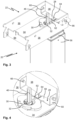
- Figure 3 shows the upper section of a table leg 20 in use position.
- Figure 4 an enlarged section with a bearing flange 30, an upper end of a threaded spindle 32 and the sensor arm 28 is shown.
- the receiving device 22 of the table leg 20 is cup-shaped.
- the receiving device 22 has a base 34, two opposing side walls 36 , and a rear wall 38.
- the side walls 36 and the rear wall 38 protrude perpendicularly from the base 34.
- the rear wall 38 can connect the two side walls 36 to each other.
- the bearing flange 30 can be made of multiple parts. Some of the components of the bearing flange 30 can be made of plastic, in particular fiber-reinforced plastic. The bearing flange can have a soft component, in particular for noise dampening during adjustment.
- the bearing flange 30 is inserted into a recess of the base 34, see also Figure 5 .
- An outer part 40 of the bearing flange 30 engages on the top and bottom sides over an edge of the recess in the base 34. This secures the outer part 40 to the base 34.
- An inner part 42 of the bearing flange 30 is secured to the threaded spindle 32.
- the inner part 42 is neither displaceable nor rotatable relative to the threaded spindle 32.
- a bearing 44 for example a rolling bearing, is arranged between the inner part 42 and the outer part 40.
- the threaded spindle 32 is rotatably supported on the receiving device 22 by the bearing flange 30. Rotation does not cause any (translational) displacement of the threaded spindle 32 relative to the receiving device 22. Forces acting along the threaded spindle 32 are introduced into the base 34 of the receiving device 22 via the bearing flange 30.
- the threaded spindle 32 has a coupling section 46 (see in particular Figures 3 and 4 ) for a 48 engine (compare Figure 5 ).
- the coupling section 46 can be configured in the form of an external polygon, here a hexagon.
- the motor 48 can engage directly on the coupling section 46 and be supported on the receiving device 22.
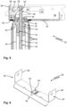
- the threaded spindle 32 has an external thread section 50.
- the external thread section 50 engages in a Internal thread section 52 of a threaded piece 54 of the base part 24.
- the threaded piece 54 is held non-rotatably on the base part 24, here via a tube section 55, which can be made of aluminum.
- the base part 24 and the receiving device 22 are connected to one another via several, here three, interleaved tube elements 56 and are fixed in their rotational orientation relative to one another. A rotation of the threaded spindle 32 thus causes a change in the length or height of the table leg 20 or table 10.
- Figure 6 shows a first variant of the sensor arm 28.
- the sensor arm 28 is designed according to the Figures 3 to 6 Formed as a bent sheet metal part. A sheet thickness can be less than 1 mm.
- the sensor arm 28 has a main section 58 and two fastening sections 60 angled relative to the main section 58, here angled at right angles.
- a contact tongue 62 protrudes from the main section 58.
- the contact tongue 62 can be angled relative to the main section 60, for example, between 5° and 25°.
- the sensor arm 28 is mirror-symmetrical with respect to a center plane through the contact tongue 62.
- a strain gauge 64 is arranged on the sensor arm 28.
- the strain gauge 64 comprises at least one, here two, strain gauges (not shown in detail).
- the two strain gauges can be connected to form a half-bridge.
- the strain gauge 64 is attached centrally to the main section 58 of the sensor arm 28 at the level of the contact tongue 62.
- the strain gauges of the strain gauge 64 can be glued to the sensor arm.
- the main section 58 and the fastening sections 60 could be stiffened on both sides of the strain measuring device 64 by means of ribs not shown in detail, for example embossed beads.
- the sensor arm 28 is connected at both ends to the side walls 36 of the receiving device 22 via a rivet 66 , see Figures 3 to 5
- the rivets 66 penetrate recesses in the fastening sections 60 of the sensor arm 28 and in the side walls 36.
- the rivets 66 can penetrate recesses in the cross member 16 and connect the table leg 20 to the cross member 16.
- the sensor arm 28 is supported on the rear wall 38 of the receiving device 22, see in particular Figure 5 .
- the sensor arm 28 can have extensions 68 for this purpose (see also Figure 6 ), which rest against the rear wall 38. Due to the rivet connection with the side walls 36 and the contact with the rear wall 38, the sensor arm 28 is firmly fixed to the receiving device 22.
- the sensor arm 28 rests with its contact tongue 62 against the bearing flange 30. Specifically, the contact tongue 62 is placed from above onto the outer part 40 of the bearing flange 30.
- the sensor arm 28 is designed and secured such that the contact tongue 28 always remains in contact with the bearing flange 30 when the table leg 20 is loaded or unloaded. For this purpose, the sensor arm 28 can be preloaded during assembly.
- the bearing flange 30 moves slightly relative to the coupling points for the sensor arm 28 on the support device 22, particularly due to elastic deformation. This leads to a deformation of the sensor arm 28, particularly in the area of the strain gauge 64.
- the support device 22 and the bearing flange 30 are significantly stiffer than the sensor arm 28. The sensor arm 28 therefore does not contribute significantly to load transfer.
- the sensor arm 28 merely absorbs the deformation of the support device 22 and the bearing flange 30, so that this can be detected by the strain gauge 64.
- a control device 70 monitors the strain gauge 64.
- the control device 70 also serves to control the motor 48. If the control device 70 detects a rapid and/or significant change in the deformation state of the sensor arm 28 during the adjustment of the height of the table leg 20 by means of the strain gauge 64, this indicates a collision.
- the control device 70 therefore initially switches off the motor 48. Preferably, the control device 70 briefly reverses the motor 48 in order to To release the jam.
- the control device 70 can also monitor or control the strain gauge 64 and the motor 48 of a second table leg 20 of a table 10.
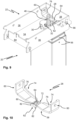
- Figure 7 shows a similar table leg 20 as the Figures 3 to 5 .
- the table leg 20 from Figure 7 differs from the previously described table leg only in the design of its sensor arm 28.
- the sensor arm 28 of the table leg 20 of Figure 7 is in Figure 8 shown.
- the sensor arm 28 is formed as a die-cast part, preferably an aluminum die-cast part.
- the sensor arm 28 has a deformation section 72 in the center.
- Guide sections 74 are formed on both sides of the deformation section 72.
- the guide sections 74 are each stiffened by a rib 76.
- the deformation section 72 in contrast, is flat on the upper side.
- Two recesses 78 are formed in the deformation section 72 on the underside.
- the recesses 78 extend on both sides of a contact tongue 62 of the sensor arm 28. Deformation of the sensor arm 28 is therefore concentrated on the deformation section 72.
- the strain gauge 64 is attached to the sensor arm 28 in the deformation section 72, here glued to the top of the sensor arm 28.
- the sensor arm 28 is attached to the side walls 36 via rivets 66 as described above.
- the sensor arm 28 rests against the rear wall 38 via the ribs 76.
- Figure 9 shows a similar table leg 20 as Figure 7 .
- the Figure 10 shown sensor arm 28 of the table leg 20 of Figure 9 Except for the design of its contact tongue 62, corresponds to the Figures 7 and 8 shown sensor arm.
- the contact tongue 62 has a neck portion 80 that protrudes from the main portion 58 of the sensor arm 28.
- Two wing portions 82 protrude laterally beyond the neck portion 80.
- the wing portions 82 bear against the bearing flange 30.
- the wing portions 82 can simulate a curvature of the bearing flange 30.
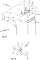
- Figure 11 shows a similar table leg 20 as the Figures 3 to 5 or 7.
- the table leg 20 of Figure 11 differs only in the design and attachment of its sensor arm 28 from the previously described table legs.
- the sensor arm 28 of the table leg 20 of Figure 11 is in Figure 12 shown.
- the sensor arm 28 is formed as a die-cast part, preferably made of aluminum. Recesses extend through a main section 58 of the sensor arm 28 on both sides of a contact tongue 62.
- the sensor arm 28 is attached to the base 34 of the receiving device 22.
- fastening sections 60 of the sensor arm 28 can protrude from the main section 58 on both sides in the manner of feet.
- Figure 13 shows a further sensor arm 28 for attachment to a base 34 of a receiving device 28 of a table leg 20, compare Figure 14 .
- the sensor arm shown is the sensor arm 28 of Figures 13 and 14 designed in the manner of a cantilever arm.
- the sensor arm 28 has a fastening section 60 at one end for attachment to the base 34.
- a free end 86 of the sensor arm 28 serves to engage the bearing flange 30.
- the invention relates to a motor-driven height-adjustable table leg with a sensor system for collision detection located outside the force flow.
- a rotatable threaded spindle is supported in a bearing flange on a support device.
- a sensor arm with a strain gauge which typically has one or more strain gauges, is attached to the support device and rests against the bearing flange without being firmly connected to it. Deformations of the bearing flange and the support device resulting from a change in load are transmitted to the sensor arm and recorded by the strain gauge.
Landscapes
- Physics & Mathematics (AREA)
- General Physics & Mathematics (AREA)
- Machine Tool Units (AREA)
- Force Measurement Appropriate To Specific Purposes (AREA)
Applications Claiming Priority (2)
| Application Number | Priority Date | Filing Date | Title |
|---|---|---|---|
| DE102021206231.8A DE102021206231A1 (de) | 2021-06-17 | 2021-06-17 | Höhenverstellbares Tischbein, Tischgestell und Tisch |
| PCT/EP2022/065684 WO2022263284A1 (de) | 2021-06-17 | 2022-06-09 | Höhenverstellbares tischbein, tischgestell und tisch |
Publications (3)
| Publication Number | Publication Date |
|---|---|
| EP4355172A1 EP4355172A1 (de) | 2024-04-24 |
| EP4355172B1 true EP4355172B1 (de) | 2025-04-30 |
| EP4355172C0 EP4355172C0 (de) | 2025-04-30 |
Family
ID=82117353
Family Applications (1)
| Application Number | Title | Priority Date | Filing Date |
|---|---|---|---|
| EP22732216.1A Active EP4355172B1 (de) | 2021-06-17 | 2022-06-09 | Höhenverstellbares tischbein, tischgestell und tisch |
Country Status (4)
| Country | Link |
|---|---|
| EP (1) | EP4355172B1 (pl) |
| DE (1) | DE102021206231A1 (pl) |
| PL (1) | PL4355172T3 (pl) |
| WO (1) | WO2022263284A1 (pl) |
Families Citing this family (1)
| Publication number | Priority date | Publication date | Assignee | Title |
|---|---|---|---|---|
| DE102020211087A1 (de) * | 2020-09-02 | 2022-03-03 | Veyhl Gmbh | Tischgestell und Tisch |
Citations (1)
| Publication number | Priority date | Publication date | Assignee | Title |
|---|---|---|---|---|
| CN217756784U (zh) * | 2022-06-15 | 2022-11-08 | 浙江捷昌线性驱动科技股份有限公司 | 具有遇阻检测功能的升降立柱及电动升降机构 |
Family Cites Families (9)
| Publication number | Priority date | Publication date | Assignee | Title |
|---|---|---|---|---|
| SE516479C2 (sv) | 2000-05-11 | 2002-01-22 | Artektron Ab | Anordning och sätt att automatiskt stoppa och/eller reversera ett motordrivet höj- och sänkbart bord vid risk för klämskada |
| AT501146B8 (de) | 2005-03-25 | 2007-02-15 | Logicdata Elect & Software Ent | Arbeitstisch |
| DK1891872T3 (da) | 2006-08-24 | 2010-07-19 | Kesseboehmer Produktions Gmbh | Indretning og fremgangsmåde til genkendelse af kollisioner ved møbler |
| EP2299870B1 (en) | 2008-06-06 | 2020-07-22 | Linak A/S | Adjustable article of furniture |
| SE0802030L (sv) | 2008-09-24 | 2009-11-17 | Swedestyle Ab | Anordning för montering av en bordsskiva på ett stativ med drivorgan |
| DK200901249A (da) | 2009-11-26 | 2011-05-27 | Linak As | Lineær aktuator med klembeskyttelse |
| DE102009058422B4 (de) | 2009-12-16 | 2015-05-07 | Logicdata Electronic & Software Entwicklungs Gmbh | Vorrichtung und Verfahren zur Kollisionserkennung eines beweglichen Möbelanteils mit einem Hindernis |
| EP2583586B2 (de) | 2011-10-18 | 2021-08-04 | Kesseböhmer Produktions GmbH & Co. KG | Vorrichtung zur Erfassung von Kollisionen und entsprechendes Verfahren |
| US9859774B2 (en) | 2012-04-23 | 2018-01-02 | Linak A/S | Linear actuator |
-
2021
- 2021-06-17 DE DE102021206231.8A patent/DE102021206231A1/de active Pending
-
2022
- 2022-06-09 EP EP22732216.1A patent/EP4355172B1/de active Active
- 2022-06-09 WO PCT/EP2022/065684 patent/WO2022263284A1/de not_active Ceased
- 2022-06-09 PL PL22732216.1T patent/PL4355172T3/pl unknown
Patent Citations (1)
| Publication number | Priority date | Publication date | Assignee | Title |
|---|---|---|---|---|
| CN217756784U (zh) * | 2022-06-15 | 2022-11-08 | 浙江捷昌线性驱动科技股份有限公司 | 具有遇阻检测功能的升降立柱及电动升降机构 |
Also Published As
| Publication number | Publication date |
|---|---|
| EP4355172A1 (de) | 2024-04-24 |
| PL4355172T3 (pl) | 2025-08-11 |
| EP4355172C0 (de) | 2025-04-30 |
| WO2022263284A1 (de) | 2022-12-22 |
| DE102021206231A1 (de) | 2022-12-22 |
Similar Documents
| Publication | Publication Date | Title |
|---|---|---|
| DE60225335T3 (de) | Einstellbare konstruktion, vorzugsweise ein möbelstück, sowie ein quetschschutz und eine antriebseinheit dafür | |
| EP1704797B1 (de) | Arbeitstisch | |
| DE102010056584B4 (de) | Mobile Arbeitsmaschine | |
| EP2512291B1 (de) | Vorrichtung und verfahren zur kollisionserkennung eines beweglichen möbelanteils mit einem hindernis | |
| DE60017328T2 (de) | Höhenmessgerät mit gekoppeltem Doppelschieber | |
| CH664434A5 (de) | Teleskopsaeule mit elektromotorischem antrieb und moebel mit der teleskopsaeule als fuss. | |
| DE102007043391A1 (de) | Aktuator mit verlagerbarem Ausleger | |
| EP2020217A1 (de) | Operationstisch | |
| EP1357367B1 (de) | Waage mit Trägerelement zur Ankopplung einer Waagschale an eine Wägezelle | |
| EP1470959B1 (de) | Trittplattenanordnung | |
| EP4355172B1 (de) | Höhenverstellbares tischbein, tischgestell und tisch | |
| DE69500404T2 (de) | Waage, insbesondere Badezimmer-Waage und Verfahren zur Montage | |
| WO2013056766A1 (de) | Lenksäule für ein kraftfahrzeug | |
| EP3099555B1 (de) | Lenkwelle für ein kraftfahrzeug | |
| WO2010086112A1 (de) | Hubvorrichtung, insbesondere für ein flurförderzeug | |
| WO2000016054A1 (de) | Kraftfahrzeugsitz mit integrierter belegungserkennung | |
| DE202021103270U1 (de) | Höhenverstellbares Tischbein, Tischgestell und Tisch | |
| DE10351988A1 (de) | Trittplattenanordnung | |
| EP1695048B1 (de) | Wägezelle | |
| WO2005102819A2 (de) | Sicherheitslenksäule für ein kraftfahrzeug | |
| EP0332213B1 (de) | Plattformwaage | |
| EP1192430A1 (de) | Kochfeld mit wägeeinheit | |
| EP2470396B1 (de) | Einstiegshilfsvorrichtung zum erleichtern eines zugangs zu einem fahrzeug | |
| EP1001247A2 (de) | Positionsgeber zur Anstellhubwegmessung der Walzen eines Walzgerüstes | |
| EP1634558B1 (de) | Pflegebett |
Legal Events
| Date | Code | Title | Description |
|---|---|---|---|
| STAA | Information on the status of an ep patent application or granted ep patent |
Free format text: STATUS: UNKNOWN |
|
| STAA | Information on the status of an ep patent application or granted ep patent |
Free format text: STATUS: THE INTERNATIONAL PUBLICATION HAS BEEN MADE |
|
| PUAI | Public reference made under article 153(3) epc to a published international application that has entered the european phase |
Free format text: ORIGINAL CODE: 0009012 |
|
| STAA | Information on the status of an ep patent application or granted ep patent |
Free format text: STATUS: REQUEST FOR EXAMINATION WAS MADE |
|
| 17P | Request for examination filed |
Effective date: 20240110 |
|
| AK | Designated contracting states |
Kind code of ref document: A1 Designated state(s): AL AT BE BG CH CY CZ DE DK EE ES FI FR GB GR HR HU IE IS IT LI LT LU LV MC MK MT NL NO PL PT RO RS SE SI SK SM TR |
|
| DAV | Request for validation of the european patent (deleted) | ||
| DAX | Request for extension of the european patent (deleted) | ||
| GRAP | Despatch of communication of intention to grant a patent |
Free format text: ORIGINAL CODE: EPIDOSNIGR1 |
|
| STAA | Information on the status of an ep patent application or granted ep patent |
Free format text: STATUS: GRANT OF PATENT IS INTENDED |
|
| INTG | Intention to grant announced |
Effective date: 20241211 |
|
| GRAS | Grant fee paid |
Free format text: ORIGINAL CODE: EPIDOSNIGR3 |
|
| GRAA | (expected) grant |
Free format text: ORIGINAL CODE: 0009210 |
|
| STAA | Information on the status of an ep patent application or granted ep patent |
Free format text: STATUS: THE PATENT HAS BEEN GRANTED |
|
| AK | Designated contracting states |
Kind code of ref document: B1 Designated state(s): AL AT BE BG CH CY CZ DE DK EE ES FI FR GB GR HR HU IE IS IT LI LT LU LV MC MK MT NL NO PL PT RO RS SE SI SK SM TR |
|
| REG | Reference to a national code |
Ref country code: CH Ref legal event code: EP Ref country code: GB Ref legal event code: FG4D Free format text: NOT ENGLISH |
|
| REG | Reference to a national code |
Ref country code: DE Ref legal event code: R096 Ref document number: 502022003795 Country of ref document: DE |
|
| REG | Reference to a national code |
Ref country code: IE Ref legal event code: FG4D Free format text: LANGUAGE OF EP DOCUMENT: GERMAN |
|
| U01 | Request for unitary effect filed |
Effective date: 20250507 |
|
| U07 | Unitary effect registered |
Designated state(s): AT BE BG DE DK EE FI FR IT LT LU LV MT NL PT RO SE SI Effective date: 20250514 |
|
| U20 | Renewal fee for the european patent with unitary effect paid |
Year of fee payment: 4 Effective date: 20250617 |
|
| PG25 | Lapsed in a contracting state [announced via postgrant information from national office to epo] |
Ref country code: ES Free format text: LAPSE BECAUSE OF FAILURE TO SUBMIT A TRANSLATION OF THE DESCRIPTION OR TO PAY THE FEE WITHIN THE PRESCRIBED TIME-LIMIT Effective date: 20250430 |
|
| PG25 | Lapsed in a contracting state [announced via postgrant information from national office to epo] |
Ref country code: NO Free format text: LAPSE BECAUSE OF FAILURE TO SUBMIT A TRANSLATION OF THE DESCRIPTION OR TO PAY THE FEE WITHIN THE PRESCRIBED TIME-LIMIT Effective date: 20250730 Ref country code: GR Free format text: LAPSE BECAUSE OF FAILURE TO SUBMIT A TRANSLATION OF THE DESCRIPTION OR TO PAY THE FEE WITHIN THE PRESCRIBED TIME-LIMIT Effective date: 20250731 |
|
| PGFP | Annual fee paid to national office [announced via postgrant information from national office to epo] |
Ref country code: PL Payment date: 20250623 Year of fee payment: 4 |
|
| PG25 | Lapsed in a contracting state [announced via postgrant information from national office to epo] |
Ref country code: HR Free format text: LAPSE BECAUSE OF FAILURE TO SUBMIT A TRANSLATION OF THE DESCRIPTION OR TO PAY THE FEE WITHIN THE PRESCRIBED TIME-LIMIT Effective date: 20250430 |
|
| PGFP | Annual fee paid to national office [announced via postgrant information from national office to epo] |
Ref country code: CH Payment date: 20250701 Year of fee payment: 4 |
|
| PG25 | Lapsed in a contracting state [announced via postgrant information from national office to epo] |
Ref country code: RS Free format text: LAPSE BECAUSE OF FAILURE TO SUBMIT A TRANSLATION OF THE DESCRIPTION OR TO PAY THE FEE WITHIN THE PRESCRIBED TIME-LIMIT Effective date: 20250731 |
|
| PG25 | Lapsed in a contracting state [announced via postgrant information from national office to epo] |
Ref country code: IS Free format text: LAPSE BECAUSE OF FAILURE TO SUBMIT A TRANSLATION OF THE DESCRIPTION OR TO PAY THE FEE WITHIN THE PRESCRIBED TIME-LIMIT Effective date: 20250830 |
|
| PG25 | Lapsed in a contracting state [announced via postgrant information from national office to epo] |
Ref country code: SM Free format text: LAPSE BECAUSE OF FAILURE TO SUBMIT A TRANSLATION OF THE DESCRIPTION OR TO PAY THE FEE WITHIN THE PRESCRIBED TIME-LIMIT Effective date: 20250430 |
|
| PG25 | Lapsed in a contracting state [announced via postgrant information from national office to epo] |
Ref country code: CZ Free format text: LAPSE BECAUSE OF FAILURE TO SUBMIT A TRANSLATION OF THE DESCRIPTION OR TO PAY THE FEE WITHIN THE PRESCRIBED TIME-LIMIT Effective date: 20250430 |
|
| PG25 | Lapsed in a contracting state [announced via postgrant information from national office to epo] |
Ref country code: SK Free format text: LAPSE BECAUSE OF FAILURE TO SUBMIT A TRANSLATION OF THE DESCRIPTION OR TO PAY THE FEE WITHIN THE PRESCRIBED TIME-LIMIT Effective date: 20250430 |
|
| PG25 | Lapsed in a contracting state [announced via postgrant information from national office to epo] |
Ref country code: MC Free format text: LAPSE BECAUSE OF FAILURE TO SUBMIT A TRANSLATION OF THE DESCRIPTION OR TO PAY THE FEE WITHIN THE PRESCRIBED TIME-LIMIT Effective date: 20250430 |