EP4354982A2 - Verfahren und vorrichtung zur leistungsregelung - Google Patents
Verfahren und vorrichtung zur leistungsregelung Download PDFInfo
- Publication number
- EP4354982A2 EP4354982A2 EP23213900.6A EP23213900A EP4354982A2 EP 4354982 A2 EP4354982 A2 EP 4354982A2 EP 23213900 A EP23213900 A EP 23213900A EP 4354982 A2 EP4354982 A2 EP 4354982A2
- Authority
- EP
- European Patent Office
- Prior art keywords
- data channel
- channel part
- transmit power
- terminal device
- bandwidth
- Prior art date
- Legal status (The legal status is an assumption and is not a legal conclusion. Google has not performed a legal analysis and makes no representation as to the accuracy of the status listed.)
- Granted
Links
Images




Classifications
-
- H—ELECTRICITY
- H04—ELECTRIC COMMUNICATION TECHNIQUE
- H04W—WIRELESS COMMUNICATION NETWORKS
- H04W52/00—Power management, e.g. Transmission Power Control [TPC] or power classes
- H04W52/04—Transmission power control [TPC]
- H04W52/30—Transmission power control [TPC] using constraints in the total amount of available transmission power
- H04W52/32—TPC of broadcast or control channels
- H04W52/325—Power control of control or pilot channels
-
- H—ELECTRICITY
- H04—ELECTRIC COMMUNICATION TECHNIQUE
- H04W—WIRELESS COMMUNICATION NETWORKS
- H04W52/00—Power management, e.g. Transmission Power Control [TPC] or power classes
- H04W52/04—Transmission power control [TPC]
- H04W52/18—TPC being performed according to specific parameters
- H04W52/24—TPC being performed according to specific parameters using SIR [Signal to Interference Ratio] or other wireless path parameters
- H04W52/242—TPC being performed according to specific parameters using SIR [Signal to Interference Ratio] or other wireless path parameters taking into account path loss
-
- H—ELECTRICITY
- H04—ELECTRIC COMMUNICATION TECHNIQUE
- H04W—WIRELESS COMMUNICATION NETWORKS
- H04W52/00—Power management, e.g. Transmission Power Control [TPC] or power classes
- H04W52/04—Transmission power control [TPC]
- H04W52/18—TPC being performed according to specific parameters
- H04W52/24—TPC being performed according to specific parameters using SIR [Signal to Interference Ratio] or other wireless path parameters
- H04W52/245—TPC being performed according to specific parameters using SIR [Signal to Interference Ratio] or other wireless path parameters taking into account received signal strength
-
- H—ELECTRICITY
- H04—ELECTRIC COMMUNICATION TECHNIQUE
- H04W—WIRELESS COMMUNICATION NETWORKS
- H04W52/00—Power management, e.g. Transmission Power Control [TPC] or power classes
- H04W52/04—Transmission power control [TPC]
- H04W52/18—TPC being performed according to specific parameters
- H04W52/26—TPC being performed according to specific parameters using transmission rate or quality of service QoS [Quality of Service]
- H04W52/267—TPC being performed according to specific parameters using transmission rate or quality of service QoS [Quality of Service] taking into account the information rate
-
- H—ELECTRICITY
- H04—ELECTRIC COMMUNICATION TECHNIQUE
- H04W—WIRELESS COMMUNICATION NETWORKS
- H04W52/00—Power management, e.g. Transmission Power Control [TPC] or power classes
- H04W52/04—Transmission power control [TPC]
- H04W52/18—TPC being performed according to specific parameters
- H04W52/28—TPC being performed according to specific parameters using user profile, e.g. mobile speed, priority or network state, e.g. standby, idle or non-transmission
- H04W52/281—TPC being performed according to specific parameters using user profile, e.g. mobile speed, priority or network state, e.g. standby, idle or non-transmission taking into account user or data type priority
-
- H—ELECTRICITY
- H04—ELECTRIC COMMUNICATION TECHNIQUE
- H04W—WIRELESS COMMUNICATION NETWORKS
- H04W52/00—Power management, e.g. Transmission Power Control [TPC] or power classes
- H04W52/04—Transmission power control [TPC]
- H04W52/30—Transmission power control [TPC] using constraints in the total amount of available transmission power
- H04W52/34—TPC management, i.e. sharing limited amount of power among users or channels or data types, e.g. cell loading
- H04W52/346—TPC management, i.e. sharing limited amount of power among users or channels or data types, e.g. cell loading distributing total power among users or channels
-
- H—ELECTRICITY
- H04—ELECTRIC COMMUNICATION TECHNIQUE
- H04W—WIRELESS COMMUNICATION NETWORKS
- H04W52/00—Power management, e.g. Transmission Power Control [TPC] or power classes
- H04W52/04—Transmission power control [TPC]
- H04W52/30—Transmission power control [TPC] using constraints in the total amount of available transmission power
- H04W52/36—Transmission power control [TPC] using constraints in the total amount of available transmission power with a discrete range or set of values, e.g. step size, ramping or offsets
- H04W52/367—Power values between minimum and maximum limits, e.g. dynamic range
-
- H—ELECTRICITY
- H04—ELECTRIC COMMUNICATION TECHNIQUE
- H04W—WIRELESS COMMUNICATION NETWORKS
- H04W52/00—Power management, e.g. Transmission Power Control [TPC] or power classes
- H04W52/04—Transmission power control [TPC]
- H04W52/38—TPC being performed in particular situations
- H04W52/383—TPC being performed in particular situations power control in peer-to-peer links
Definitions
- This application relates to the field of communications technologies, and in particular, to a power control method and apparatus.
- V2X vehicle-to-everything
- the V2X communication refers to communication between a vehicle and everything outside the vehicle, and includes vehicle-to-vehicle (vehicle to vehicle, V2V) communication, vehicle-to-pedestrian (vehicle to pedestrian, V2P) communication, vehicle-to-infrastructure (vehicle-to-infrastructure, V2I) communication, and vehicle-to-network (vehicle to network, V2N) communication.
- V2V vehicle to vehicle to vehicle
- V2P vehicle-to-pedestrian
- V2I vehicle-to-infrastructure
- V2N vehicle-to-network
- the V2X communication is intended for high-speed devices such as vehicles, and is a basic and key technology applied to a scenario with a very high requirement for communication latency in the future.
- the scenario may be a scenario involving an intelligent vehicle, self-driving, or an intelligent transportation system.
- a vehicle user can periodically send, to surrounding vehicle users, some information of the vehicle user, for example, information about a location, a speed, intent (turning, merging, reversing), and some information triggered by aperiodic events.
- the vehicle user may receive information about surrounding users in real time.
- a service type mainly used in LTE-V2X is a broadcast message. Therefore, a V2X receive end user is not determined, and all interested V2X users may be in a listening state. Therefore, a transmit end sends data information at a maximum transmit power.
- an LTE-V2X signal is sent in an uplink slot, and interference of a V2X transmit power to uplink receiving on a base station side needs to be considered.
- Embodiments of this application provide a power control method and apparatus, so that power control can be properly performed.
- an embodiment of this application provides a power control method, including: A first terminal device determines a transmit power of a first data channel part and a transmit power of a second data channel part, where the first data channel part is a data channel part that overlaps a control channel in time domain and does not overlap the control channel in frequency domain, and the second data channel part is a data channel part that overlaps the control channel in frequency domain and does not overlap the control channel in time domain.
- the first terminal device sends data in the first data channel part to a second terminal device at the transmit power of the first data channel part, and sends data in the second data channel part to the second terminal device at the transmit power of the second data channel part.
- Power control may be performed differently on different data channel parts by distinguishing between the first data channel part and the second data channel part.
- the data in the first data channel part and the data in the second data channel part may be sent at different transmit powers. This avoids sending of data at a same transmit power in all cases, thereby avoiding a waste of resources. For example, this avoids a case in which the transmit power of the first data channel part or the second data channel part is excessively high when a transmit power of a data channel is determined based on a same manner, and actually, data can be sent without the excessively high transmit power.
- the data channel is divided into two parts, and transmit powers of the two parts are determined respectively.
- a bandwidth of the control channel is N
- a bandwidth of a data channel is M
- a bandwidth of the first data channel part is M-N, where M is greater than N.
- the transmit power of the first data channel part is determined based on a maximum transmit power, the bandwidth M-N of the first data channel part, and the bandwidth N of the control channel.
- P 1 is the transmit power of the first data channel part
- P CMAX is the maximum transmit power
- f ( N , M - N ) is a function of the bandwidth M-N of the first data channel part and the bandwidth N of the control channel
- f ( M - N) is a function of the bandwidth M-N of the first data channel part
- P o is a target received power of the second terminal device
- PL is a reference link loss.
- the transmit power of the first data channel part is determined based on the actual bandwidth M-N of the first data channel part, to avoid a case in which a transmit power of the data channel is inaccurately determined because there are a first data channel part and a second data channel part that have different bandwidths on the data channel. In this way, accuracy of determining the transmit power of the first data channel part is improved.
- a ratio of the transmit power of the second data channel part to the transmit power of the first data channel part is positively correlated with a ratio of a bandwidth of the second data channel part to the bandwidth of the first data channel part.
- P 2 is the transmit power of the second data channel part
- f ( M / ( M - N )) is a function of a bandwidth M of the second data channel part and the bandwidth M-N of the first data channel part.
- data is sent at a same transmit power on a resource element (resource element, RE) in the first data channel part and an RE in the second data channel part, and the ratio of the bandwidth of the first data channel part to the bandwidth of the second data channel part is used to determine the ratio of the transmit power of the first data channel part to the transmit power of the second data channel part.
- RE resource element
- this may effectively resolve a problem that available effective bandwidths on different symbols (symbol) on the data channel are different.
- the second terminal device may scale the second data channel part based on the intermediate frequency scaling factor of the first data channel part and the ratio of the bandwidth of the first data channel part to the bandwidth of the second data channel part. Therefore, received data of an entire slot is in a proper received power range.
- the transmit power of the second data channel part is determined based on the maximum transmit power, and a link budget of the second data channel part, and the link budget of the second data channel part is determined based on a bandwidth M of the second data channel part.
- P 2 is the transmit power of the second data channel part
- P CMAX is the maximum transmit power
- f ( M ) is a function of the bandwidth M of the second data channel part
- P o is the target received power of the second terminal device
- PL is the reference link loss.
- data is sent at different transmit powers on the RE in the first data channel part and the RE in the second data channel part, so that the transmit power of the data channel can be maximized.
- a transmit power of each RE in the second data channel part is increased as much as possible. Therefore, a higher SNR is obtained, and decoding performance is improved.
- the reference link loss PL is determined based on an uplink/downlink transmission loss in a serving cell or a link transmission loss, and the link transmission loss includes a sidelink transmission loss; and the link transmission loss is a link loss from the first terminal device to the second terminal device; the link transmission loss is a largest value of link losses from the first terminal device to terminal devices that are in a first terminal device set; or the link transmission loss is a largest value of link losses from the first terminal device to terminal devices that are in a second terminal device set, where the second terminal device set belongs to the first terminal device set, and a first parameter of the terminal device in the second terminal device set satisfies a threshold range of the first parameter.
- the first parameter is any one of a reference signal received power RSRP, a signal to interference plus noise ratio SINR, a signal-to-noise ratio SNR, or a channel quality indicator CQI.
- the reference link loss is determined based on the uplink/downlink transmission loss in the serving cell or the link transmission loss, to reduce a transmit power of the first terminal device, thereby reducing interference to another terminal device, and improving system performance.
- the method before the first terminal device determines the transmit power of the first data channel part and the transmit power of the second data channel part, the method further includes:
- the indication information from the network device is received, so that the first terminal device clearly learns of a condition that the transmit power of the second data channel part satisfies, thereby improving efficiency of determining the transmit power of the second data channel part by the first terminal device.
- P 1 is the transmit power of the first data channel part
- P CMAX is the maximum transmit power
- f ( N , M - N) is a function of the bandwidth M-N of the first data channel part and the bandwidth N of the control channel
- f ( M - N ) is a function of the bandwidth M-N of the first data channel part
- P o is a target received power of the second terminal device
- PL is a reference link loss
- P T is a transmit power positively correlated with a priority of a service carried by data sent on the data channel.
- P 2 is the transmit power of the second data channel part
- P CMAX is the maximum transmit power
- f(M) is a function of a bandwidth M of the second data channel part
- P o is a target received power of the second terminal device
- PL is a reference link loss
- P T is a transmit power positively correlated with a priority of a service carried by data sent on the data channel.
- P T is a semi-static value configured by a network device, or P T is a preconfigured fixed value.
- the transmit power of the first data channel part and the transmit power of the second data channel part are determined based on P T , so that a high-priority service is preferably transmitted, and transmission reliability of the high-priority service is improved.
- P 1 is the transmit power of the first data channel part
- P CMAX is the maximum transmit power
- f ( N , M - N) is a function of the bandwidth M-N of the first data channel part and the bandwidth N of the control channel
- f ( M - N) is a function of the bandwidth M-N of the first data channel part
- P o is a target received power of the second terminal device
- PL is a reference link loss
- P MAX_CBR is a power determined based on a channel busy degree.
- P 2 is the transmit power of the second data channel part
- P CMAX is the maximum transmit power
- f(M) is a function of a bandwidth M of the second data channel part
- P o is a target received power of the second terminal device
- PL is a reference link loss
- P MAX_CBR is a power determined based on a channel busy degree.
- an embodiment of this application provides a power control apparatus, including: a processing unit, configured to determine a transmit power of a first data channel part and a transmit power of a second data channel part, where the first data channel part is a data channel part that overlaps a control channel in time domain and does not overlap the control channel in frequency domain, and the second data channel part is a data channel part that overlaps the control channel in frequency domain and does not overlap the control channel in time domain; and a sending unit, configured to: send data in the first data channel part to a second terminal device at the transmit power of the first data channel part, and send data in the second data channel part to the second terminal device at the transmit power of the second data channel part.
- a bandwidth of the control channel is N
- a bandwidth of a data channel is M
- a bandwidth of the first data channel part is M-N, where M is greater than N.
- the transmit power of the first data channel part is determined based on a maximum transmit power, the bandwidth M-N of the first data channel part, and the bandwidth N of the control channel.
- P 1 is the transmit power of the first data channel part
- P CMAX is the maximum transmit power
- f ( N , M - N) is a function of the bandwidth M-N of the first data channel part and the bandwidth N of the control channel
- f ( M - N) is a function of the bandwidth M-N of the first data channel part
- P o is a target received power of the second terminal device
- PL is a reference link loss.
- a ratio of the transmit power of the second data channel part to the transmit power of the first data channel part is positively correlated with a ratio of a bandwidth of the second data channel part to the bandwidth of the first data channel part.
- P 2 is the transmit power of the second data channel part
- f ( M / (M - N )) is a function of a bandwidth M of the second data channel part and the bandwidth M-N of the first data channel part.
- the transmit power of the second data channel part is determined based on the maximum transmit power, and a link budget of the second data channel part, and the link budget of the second data channel part is determined based on a bandwidth M of the second data channel part.
- P 2 is the transmit power of the second data channel part
- P CMAX is the maximum transmit power
- f ( M ) is a function of the bandwidth M of the second data channel part
- P o is the target received power of the second terminal device
- PL is the reference link loss.
- the reference link loss PL is determined based on an uplink/downlink transmission loss in a serving cell or a link transmission loss, and the link transmission loss includes a sidelink transmission loss; and the link transmission loss is a link loss from the first terminal device to the second terminal device; the link transmission loss is a largest value of link losses from the first terminal device to terminal devices that are in a first terminal device set; or the link transmission loss is a largest value of link losses from the first terminal device to terminal devices that are in a second terminal device set, where the second terminal device set belongs to the first terminal device set, and a first parameter of the terminal device in the second terminal device set satisfies a threshold range of the first parameter.
- the first parameter is any one of a reference signal received power RSRP, a signal to interference plus noise ratio SINR, a signal-to-noise ratio SNR, or a channel quality indicator CQI.
- the apparatus further includes: a receiving unit, configured to receive indication information from a network device, where the indication information is used to indicate the transmit power of the second data channel part.
- P 1 is the transmit power of the first data channel part
- P CMAX is the maximum transmit power
- f ( N , M - N) is a function of the bandwidth M-N of the first data channel part and the bandwidth N of the control channel
- f ( M - N) is a function of the bandwidth M-N of the first data channel part
- P o is a target received power of the second terminal device
- PL is a reference link loss
- P T is a transmit power positively correlated with a priority of a service carried by data sent on the data channel.
- P 2 is the transmit power of the second data channel part
- P CMAX is the maximum transmit power
- f(M) is a function of a bandwidth M of the second data channel part
- P o is a target received power of the second terminal device
- PL is a reference link loss
- P T is a transmit power positively correlated with a priority of a service carried by data sent on the data channel.
- P T is a semi-static value configured by a network device, or P T is a preconfigured fixed value.
- P 1 is the transmit power of the first data channel part
- P CMAX is the maximum transmit power
- f ( N , M - N) is a function of the bandwidth M-N of the first data channel part and the bandwidth N of the control channel
- f ( M - N ) is a function of the bandwidth M-N of the first data channel part
- P o is a target received power of the second terminal device
- PL is a reference link loss
- P MAX_CBR is a power determined based on a channel busy degree.
- P 2 is the transmit power of the second data channel part
- P CMAX is the maximum transmit power
- f ( M ) is a function of a bandwidth M of the second data channel part
- P o is a target received power of the second terminal device
- PL is a reference link loss
- P MAX_CBR is a power determined based on a channel busy degree.
- an embodiment of this application further provides a power control apparatus, including a processor, a memory, and a transceiver, where the processor is coupled to the memory, and the processor is configured to run instructions or programs in the memory.
- the processor is configured to determine a transmit power of a first data channel part and a transmit power of a second data channel part, where the first data channel part is a data channel part that overlaps a control channel in time domain and does not overlap the control channel in frequency domain, and the second data channel part is a data channel part that overlaps the control channel in frequency domain and does not overlap the control channel in time domain.
- the transceiver is coupled to the processor, and the transceiver is configured to: send data in the first data channel part to a second terminal device at the transmit power of the first data channel part, and send data in the second data channel part to the second terminal device at the transmit power of the second data channel part.
- a bandwidth of the control channel is N
- a bandwidth of a data channel is M
- a bandwidth of the first data channel part is M-N, where M is greater than N.
- the transmit power of the first data channel part is determined based on a maximum transmit power, the bandwidth M-N of the first data channel part, and the bandwidth N of the control channel.
- P 1 is the transmit power of the first data channel part
- P CMAX is the maximum transmit power
- f ( N,M-N ) is a function of the bandwidth M-N of the first data channel part and the bandwidth N of the control channel
- f ( M - N) is a function of the bandwidth M-N of the first data channel part
- P o is a target received power of the second terminal device
- PL is a reference link loss.
- a ratio of the transmit power of the second data channel part to the transmit power of the first data channel part is positively correlated with a ratio of a bandwidth of the second data channel part to the bandwidth of the first data channel part.
- P 2 is the transmit power of the second data channel part
- f ( M / (M - N )) is a function of a bandwidth M of the second data channel part and the bandwidth M-N of the first data channel part.
- the transmit power of the second data channel part is determined based on the maximum transmit power, and a link budget of the second data channel part, and the link budget of the second data channel part is determined based on a bandwidth M of the second data channel part.
- P 2 is the transmit power of the second data channel part
- P CMAX is the maximum transmit power
- f ( M ) is a function of the bandwidth M of the second data channel part
- P o is the target received power of the second terminal device
- PL is the reference link loss.
- the reference link loss PL is determined based on an uplink/downlink transmission loss in a serving cell or a link transmission loss, and the link transmission loss includes a sidelink transmission loss; and the link transmission loss is a link loss from the first terminal device to the second terminal device; the link transmission loss is a largest value of link losses from the first terminal device to terminal devices that are in a first terminal device set; or the link transmission loss is a largest value of link losses from the first terminal device to terminal devices that are in a second terminal device set, where the second terminal device set belongs to the first terminal device set, and a first parameter of the terminal device in the second terminal device set satisfies a threshold range of the first parameter.
- the first parameter is any one of a reference signal received power RSRP, a signal to interference plus noise ratio SINR, a signal-to-noise ratio SNR, or a channel quality indicator CQI.
- the transceiver is further configured to receive indication information from a network device, where the indication information is used to indicate the transmit power of the second data channel part.
- P 1 is the transmit power of the first data channel part
- P CMAX is the maximum transmit power
- f (N , M - N) is a function of the bandwidth M-N of the first data channel part and the bandwidth N of the control channel
- f ( M - N) is a function of the bandwidth M-N of the first data channel part
- P o is a target received power of the second terminal device
- PL is a reference link loss
- P T is a transmit power positively correlated with a priority of a service carried by data sent on the data channel.
- P 2 is the transmit power of the second data channel part
- P CMAX is the maximum transmit power
- f(M) is a function of a bandwidth M of the second data channel part
- P o is a target received power of the second terminal device
- PL is a reference link loss
- P T is a transmit power positively correlated with a priority of a service carried by data sent on the data channel.
- P T is a semi-static value configured by a network device, or P T is a preconfigured fixed value.
- P 1 is the transmit power of the first data channel part
- P CMAX is the maximum transmit power
- f ( N , M - N ) is a function of the bandwidth M-N of the first data channel part and the bandwidth N of the control channel
- f ( M - N) is a function of the bandwidth M-N of the first data channel part
- P o is a target received power of the second terminal device
- PL is a reference link loss
- P MAX_CBR is a power determined based on a channel busy degree.
- P 2 is the transmit power of the second data channel part
- P CMAX is the maximum transmit power
- f(M) is a function of a bandwidth M of the second data channel part
- P o is a target received power of the second terminal device
- PL is a reference link loss
- P MAX_CBR is a power determined based on a channel busy degree.
- an embodiment of this application provides a computer-readable storage medium.
- the computer-readable storage medium stores instructions; and when the instructions are run on a computer, the computer is enabled to perform the method according to the foregoing aspects.
- an embodiment of this application provides a computer program product including instructions; and when the computer program product runs on a computer, the computer is enabled to perform the method according to the foregoing aspects.
- the term "at least one (item)” means one or more
- the term "a plurality of” means two or more than two
- at least two (items) means two, three, or more than three
- the term “and/or” is used to describe an association relationship for describing associated objects and represent that three relationships may exist.
- “A and/or B” may represent three cases: Only A exists, only B exists, and both A and B exists.
- a and B may be singular or plural.
- the character “/” usually indicates an "or” relationship between the associated objects.
- "At least one of the following items (pieces)” or a similar expression thereof indicates any combination of these items, including any combination of singular items (pieces) or plural items (pieces).
- At least one item (piece) of a, b, or c may represent: a, b, c, "a and b", “a and c", “b and c", or "a, b, and c", where a, b, and c may be singular or plural.
- a communications system used in this application may be understood as a wireless cellular communications system, or may be understood as a wireless communications system based on a cellular network architecture.
- the communications system may be a 5th generation mobile communications (5th-generation, 5G) system and next generation mobile communications system.
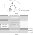
- FIG. 1a is a schematic diagram of a communications system according to an embodiment of this application. The solution in this application may be applied to the communications system.
- the communications system may include at least one network device, and only one network device is shown, for example, a next generation NodeB (the next generation Node B, gNB) in the figure.
- the communications system may further include one or more terminal devices connected to the network device, for example, a terminal device 1 and a terminal device 2 in the figure.
- the network device may be a device that can communicate with the terminal device.
- the network device may be any device with a wireless transceiver function, and includes but is not limited to a base station.
- the base station may be the gNB, or the base station may be a base station in a future communications system.
- the network device may alternatively be an access node, a wireless relay node, a wireless backhaul node, or the like in a wireless local area network (e.g. wireless fidelity, WiFi) system.
- the network device may alternatively be a radio controller in a cloud radio access network (cloud radio access network, CRAN) scenario.
- the network device may alternatively be a wearable device, a vehicle-mounted device, or the like.
- the network device may alternatively be a small cell, a transmission node (transmission reference point, TRP), or the like. Certainly, this application is not limited thereto.
- the terminal device may also be referred to as user equipment (user equipment, UE), a terminal, or the like.
- the terminal device is a device with a wireless transceiver function.
- the terminal device may be deployed on land, and includes an indoor device, an outdoor device, a handheld device, a wearable device, or a vehicle-mounted device; or may be deployed on water, for example, on a ship; or may be deployed in air, for example, on an airplane, a balloon, or a satellite.
- the terminal device may be a mobile phone (mobile phone), a tablet (e.g.
- a computer with a wireless transceiver function a virtual reality (virtual reality, VR) terminal device, an augmented reality (augmented reality, AR) terminal device, a wireless terminal in industrial control (industrial control), a wireless terminal in self-driving (self driving), a wireless terminal in telemedicine (also called remote medical surgery), a wireless terminal in a smart grid (smart grid), a wireless terminal in transportation safety (transportation safety), a wireless terminal in a smart city (smart city), a wireless terminal in a smart home (smart home), or the like.
- the terminal device 1 and the terminal device 2 may alternatively communicate with each other by using a device-to-device (device to device, D2D) technology or a vehicle-to-anything (vehicle-to-everything, V2X) communications technology.
- D2D device to device
- V2X vehicle-to-anything
- Long term evolution (long term evolution, LTE)-V2X satisfies some basic requirements in a V2X scenario, but the currently LTE V2X cannot be effectively applied to future scenarios such as fully intelligent driving and autonomous driving.
- 5G NR-V2X 5th generation mobile communications new radio (new radio, NR) technology in the 3GPP standards organization
- 5G NR-V2X proposes to support transmission with reliability of 99.99% or even 99.999%.
- the NR-V2X also needs to support unicast, multicast, and broadcast services, and the like.
- a resource diagram shown in FIG. 1b is used as an example, a control channel and a data channel are frequency division multiplexed together on a time-frequency resource that is sent once. From the perspective of time domain, the control channel and the data channel are in a coexistence relationship. Therefore, transmit powers of the control channel and the data channel need to be considered together.
- P PSCCH 10 log 10 10 3 10 ⁇ M PSCCH M PSSCH + 10 3 10 ⁇ M PSCCH + min P CMAX , 10log 10 M PSSCH + 10 3 10 ⁇ M PSCCH + P O_PSSCH ,3 + ⁇ PSSCH , 3 ⁇ PL dBm
- P PSSCH is the transmit power of the data channel
- P PSCCH is the transmit power of the control channel
- M PSSCH is a bandwidth of the data channel
- M PSCCH is a bandwidth of the control channel
- P CMAX is a maximum transmit power, or may be understood as a maximum transmit power allowed by the terminal device.
- PL is a downlink link power loss of the terminal device. In a communications system, especially in a time division duplex (time division duplexing, TDD) system, it is usually considered that uplink and downlink losses are consistent. Therefore, PL may be used to indicate a possible link loss from the terminal device to a base station side.
- P O_PSSCH_3 is a power expected to be received by the terminal device (which may also be understood as a target received power of the terminal device). 3 indicates base station scheduling. ⁇ PSSCH ,3 is a filtering parameter configured in a base station scheduling mode.
- P PSSCH min P CMAX ⁇ 10 log 10 1 + 10 3 10 ⁇ M PSCCH M PSSCH , 10 log 10 M PSSCH + P O_PSSCH ,3 + ⁇ PSSCH , 3 ⁇ PL dBm
- P PSCCH min P CMAX ⁇ 10 log 10 1 + M PSSCH 10 3 10 ⁇ M PSCCH , 10 log 10 10 3 10 ⁇ M PSCCH + P O _ PSSCH ,3 + ⁇ PSSCH , 3 ⁇ PL dBm
- the formula (3) and the formula (4) each include two sub-items, where the first item indicates a maximum transmit power allocated to a current channel.
- the first item in the formula (3) may indicate a maximum transmit power allocated to the data channel.
- the first item in the formula (4) may indicate a maximum transmit power allocated to the control channel. It can be learned from the first item that, the maximum transmit powers allocated to the control channel and the data channel are in direct proportion to the bandwidths of the channels.
- each sub-channel of the control channel has an increase of 10 3 10 times in a transmit power. In other words, all transmit powers allowed by hardware of the terminal device are allocated to the control channel and the data channel in proportion to the bandwidths.
- the second item indicates a link budget, that is, an expected transmit power of a link, calculated based on a link loss of a Uu interface and an expected signal-to-noise ratio (signal-noise-ratio, SNR).
- the transmit power of the data channel and the transmit power of the control channel are respectively minimum values in the first item and the second item.
- a link requirement that is, the link budget.
- a data channel is sent at the maximum power allowed by the terminal device.
- a system may define a maximum transmit power P MAX_CBR in a sub-channel based on a busy degree of the current sub-channel. If a quantity of terminal devices in the sub-channel is relatively large, to reduce a collision probability, a transmit power of each terminal device in the sub-channel may be reduced. Otherwise, a transmit power of each terminal device in the sub-channel may be increased.
- FIG. 2 a possible frame structure in an NR-V2X scenario is shown in FIG. 2 .
- LTE-V2X and device-to-device (device to device, D2D) power allocation manners and LTE-V2X and device-to-device power control methods are only applicable to 2a, 2b, and 2c in FIG. 2 .
- a structure shown in 2d in FIG. 2 appears in the frame structure in the NR-V2X, to be specific, a hybrid multiplexing scenario in which the control channel overlaps the data channel in both time domain and frequency domain, the LTE-V2X or D2D power allocation manner is no longer applicable. Therefore, for the power control method of the structure shown in 2d in FIG. 2 , refer to the method shown in FIG. 4 in the embodiments of this application.
- the following uses the terminal device 1 and the terminal device 2 in the NR-V2X as examples to specifically describe communication scenarios of the power control method provided in the embodiments of this application.
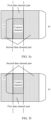
- FIG. 3a to FIG. 3g each are a schematic diagram of a sidelink (sidelink) communication scenario according to an embodiment of this application.
- both the terminal device 1 and the terminal device 2 are outside coverage of a cell.
- the terminal device 1 is in coverage of a cell, and the terminal device 2 is outside the coverage of the cell.
- both the terminal device 1 and the terminal device 2 are in coverage of a same cell, and are in a public land mobile network (public land mobile network, PLMN), for example, a PLMN 1.
- PLMN public land mobile network
- the terminal device 1 and the terminal device 2 are in one PLMN, for example, a PLMN 1, but are in coverage of different cells.
- the terminal device 1 and the terminal device 2 are respectively in different PLMNs and different cells, and the terminal device 1 and the terminal device 2 are in co-coverage of two cells.
- the terminal device 1 is in a PLMN 1
- the terminal device 2 is in a PLMN 2.
- the terminal device 1 and the terminal device 2 are respectively in different PLMNs and different cells, the terminal device 1 is in co-coverage of two cells, and the terminal device 2 is in coverage of a serving cell.
- the terminal device 1 and the terminal device 2 are respectively in different PLMNs and different cells, and the terminal device 1 and the terminal device 2 are respectively in coverage of serving cells of the terminal device 1 and the terminal device 2.
- V2X vehicle-to-everything
- V2X vehicle-to-everything
- FIG. 4 is a schematic flowchart of a power control method according to an embodiment of this application.
- the power control method may be applied to the terminal devices shown in FIG. 3a to FIG. 3g , and the power control method can effectively resolve the foregoing power control problem.
- the power control method may include the following steps.
- a first terminal device determines a transmit power of a first data channel part and a transmit power of a second data channel part.
- the first data channel part is a data channel part that overlaps a control channel in time domain and does not overlap the control channel in frequency domain
- the second data channel part is a data channel part that overlaps the control channel in frequency domain and does not overlap the control channel in time domain.
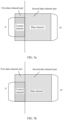
- FIG. 5a provides a schematic diagram of a data channel and a control channel.
- the data channel may be divided into a first data channel part and a second data channel part.
- the first data channel part and the second data channel part may form a complete data channel.
- the first data channel part and the second data channel part may constitute a complete data channel.
- the first data channel part overlaps the control channel in time domain but does not overlap the control channel in frequency domain
- the second data channel part overlaps the control channel in frequency domain but does not overlap the control channel in time domain.
- the first data channel part and the control channel are time domain multiplexed, but are not frequency domain multiplexed
- the second data channel part and the control channel are frequency domain multiplexed, but are not time domain multiplexed.
- a bandwidth of the data channel is M
- a bandwidth of the control channel is N
- M is greater than N
- a bandwidth of the first data channel part is M-N
- a bandwidth of the second data channel part is M.
- M may indicate M resource blocks (resource block, RB)
- N may indicate N RBs.
- the bandwidth of the data channel and the bandwidth of the control channel may be in units of subcarriers, or the like. This is not limited in this application. It may be understood that, when a subcarrier is used as a unit, the transmit power of the first data channel part, the transmit power of the second data channel part, and a transmit power of the control channel further need to be determined based on a subcarrier spacing.
- control channel may be understood as a channel used to carry sidelink control information (sidelink control information, SCI), and the SCI includes decoding information of data transmitted on the data channel, and the like.
- the data channel may be understood as a channel used to carry data.
- the data may be data sent by the first terminal device to a second terminal device. Further, the data may be used to carry service data sent by the first terminal device to the second terminal device.
- a sidelink data channel may be a physical sidelink shared channel (physical sidelink shared channel, PSSCH), and a sidelink control channel may be a physical sidelink control channel (physical sidelink control channel, PSCCH).
- a terminal device when determining a transmit power, may divide the data channel into two parts, and separately determine transmit powers of the two parts, to be specific, the transmit power of the first data channel part and the transmit power of the second data channel part.
- the following describes a detailed process in which the first terminal device determines the transmit power of the first data channel part and the transmit power of the second data channel part.
- the first terminal device sends data in the first data channel part to the second terminal device at the transmit power of the first data channel part, and sends data in the second data channel part to the second terminal device at the transmit power of the second data channel part.
- power control may be performed differently on different data channel parts by distinguishing between the first data channel part and the second data channel part.
- the data in the first data channel part and the data in the second data channel part may be sent at different transmit powers. This avoids sending of data at a same transmit power in all cases, thereby avoiding a waste of resources. For example, this avoids a case in which the transmit power of the first data channel part or the second data channel part is excessively high when the transmit power of the data channel is determined based on a same manner, and actually, data can be sent without the excessively high transmit power.
- the data channel is divided into two parts, and transmit powers of the two parts are determined respectively.
- the first terminal device determines the transmit power of the control channel, the transmit power of the first data channel part, and the transmit power of the second data channel part is described in detail. It may be understood that, the following uses the schematic diagram of the control channel and the data channel shown in FIG. 5a for description.
- P control is the transmit power of the control channel
- P CMAX is the maximum transmit power
- f(M - N, N ) is a function of the bandwidth M-N of the first data channel part and the bandwidth N of the control channel
- f ( N ) is a function of the bandwidth N of the control channel
- P o is a target received power of the second terminal device (which may also be understood as a received power expected by the second terminal device)
- ⁇ is a filtering parameter specified (by a base station) for considering to adjust stability, and may be configured by a higher layer
- PL is a reference link loss.
- P CMAX may be understood as a maximum transmit power limited by physical hardware, or may be understood as a maximum transmit power allowed by hardware of the terminal device.
- P CMAX may be configured by using higher layer signaling of the base station.
- f ( M - N,N ) in the formula (9) may also be understood as an expression of the bandwidth M-N of the first data channel part and the bandwidth N of the control channel, or may be understood as a relational expression between the bandwidth M-N of the first data channel part and the bandwidth N of the control channel, or the like.
- P CMAX - f ( M-N , N ) may be understood as a transmit power allocated to the control channel based on the maximum transmit power P CMAX and a ratio of the bandwidth of the control channel to the bandwidth of the first data channel part, and f ( N )+ P O + ⁇ PL may be understood as a link budget of the control channel.
- f ( M-N,N ) may be understood as a power allocation relationship between the control channel and the first data channel part.
- the formula (12) and the formula (13) are two different forms of the transmit power of the control channel in a base station scheduling mode.
- the first terminal device may alternatively determine the transmit power of the control channel by using the formula (9) and further by using the formula (12) or the formula (13), so that the first terminal device sends control information on the control channel to the second terminal device at the transmit power of the control channel.
- P control is the transmit power of the control channel
- P CMAX is the maximum transmit power
- f ( M - N,N ) is the function of the bandwidth M-N of the first data channel part and the bandwidth N of the control channel
- f ( N ) is the function of the bandwidth N of the control channel
- Po is the target received power of the second terminal device
- ⁇ is the filtering parameter specified for considering to adjust stability, and may be configured by the higher layer
- PL is the reference link loss
- P MAX_CBR is a power determined based on a channel busy degree, or may be understood as a busy power (max channel busy ratio).
- formula (15) and the formula (16) are two different forms of the transmit power of the control channel, and transmit powers, of the control channel, determined by the first terminal device by using the formula (15) and the formula (16) are consistent.
- determining the transmit power of the control channel may be further based on a priority of the control information.
- P T is a transmit power positively correlated with the priority of the control information that is sent on the control channel.
- P T is a semi-static value configured by a network device, or P T is a preconfigured fixed value. It may be understood that for descriptions of other parameters, refer to other examples. Details are not described herein.
- P T may be configured by using higher layer signaling, for example, configured by using higher layer signaling of the network device.
- the formula (17) and the formula (18) may be understood as that, in the base station scheduling mode, different control information may include different priorities.
- a power control method is used to determine the transmit power of the control channel based on the transmit power allocated to the control channel, the link budget of the control channel, and a threshold power (P T ) of the control channel.
- the transmit power of the control channel may have another variation. Therefore, the foregoing embodiments should not be construed as a limitation on this application.
- P 1 is the transmit power of the first data channel part
- P CMAX is the maximum transmit power
- f ( N , M - N ) is the function of the bandwidth M-N of the first data channel part and the bandwidth N of the control channel
- f ( M - N) is the function of the bandwidth M-N of the first data channel part
- P o is the target received power of the second terminal device
- ⁇ is the filtering parameter specified for considering to adjust stability, and may be configured by the higher layer
- PL is the reference link loss.
- f(N,M - N ) may be further understood as an expression, a relational expression, or the like between the bandwidth M-N of the first data channel part and the bandwidth N of the control channel
- f ( M - N ) may be further understood as an expression, a relational expression, or the like of the bandwidth M-N of the first data channel part.
- P CMAX - f ( N,M-N ) may be understood as a transmit power allocated to the first data channel part based on the maximum transmit power P CMAX and a ratio of the bandwidth of the first data channel part to the bandwidth of the control channel, and f ( M-N )+ P O + ⁇ PL may be understood as a link budget of the first data channel part.
- the formula (24) and the formula (25) are two different forms of the transmit power of the first data channel part, and transmit powers, of the first data channel part, determined by the first terminal device by using the formula (24) and the formula (25) are consistent.
- P MAX_CBR is a power determined based on the channel busy degree. It may be understood that P MAX_CBR in the formula (14) and the formula (26) may be understood as a same busy power.
- the services carried by the data sent on the data channel may be limited by using different powers. For example, when a service that has a relatively high security requirement, for example, emergency avoidance and automatic driving, is involved, the service that has a relatively high security requirement has a relatively high QoS requirement. In other words, in these scenarios that have relatively high security requirements, the service carried by the data sent on the data channel requires higher QoS. Therefore, in some embodiments of this application, the first terminal device may determine the transmit power of the first data channel part based on the QoS requirement of the service.
- QoS quality of service
- P T is a transmit power positively correlated with a priority of the service carried by the data sent on the data channel.
- P T is a semi-static value configured by the network device, or P T is a preconfigured fixed value.
- P T may also be understood as a threshold power, in other words, a higher priority of a service indicates higher P T .
- a high-priority service corresponds to a high-threshold power
- a low-priority service corresponds to a low-threshold power.
- different threshold powers are set based on QoS requirements of different services, so that reliability of transmission of a high-priority service carried by the first terminal device can be ensured.
- different power threshold limitations can be set for services with different priorities, so that the high-priority service has higher reliability when interference is the same.
- the formula (29) and the formula (30) may be understood as that, in the base station scheduling mode, different threshold powers are set based on QoS requirements of different services, so that a method is used to determine the transmit power of the first data channel part based on the transmit power allocated to the first data channel part, the link budget of the first data channel part, and a threshold power of the first data channel part.
- This embodiment provides two implementations to describe the transmit power of the second data channel part, and the two implementations are respectively as follows.
- a ratio of the transmit power of the second data channel part to the transmit power of the first data channel part is positively correlated with a ratio of a bandwidth of the second data channel part to the bandwidth of the first data channel part.
- the ratio of the transmit power of the second data channel part to the transmit power of the first data channel part is the same as the ratio of the bandwidth of the second data channel part to the bandwidth of the first data channel part.
- data is sent at a same transmit power on each resource element (resource element, RE) of the data channel.
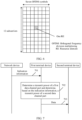
- FIG. 6 is a schematic structural diagram of a time-frequency resource according to an embodiment of this application.
- One RE is one orthogonal frequency division multiplexing (orthogonal frequency division multiplexing, OFDM) symbol in time domain, and is one subcarrier in frequency domain.
- the time-frequency resource is divided into an OFDM symbol or a single-carrier frequency division multiple access (single carrier frequency division multiplexing access, SC-FDMA) symbol in a time domain dimension and a subcarrier in a frequency domain dimension, and a minimum resource granularity is referred to as an RE.
- the RE indicates a time-frequency box including one time-domain symbol in time domain and one subcarrier in frequency domain. It may be understood that, the foregoing is merely an example provided in this embodiment of this application. In a future communications technology, a structure of the RE may change. Therefore, the RE shown in FIG. 6 should not be understood as a limitation on this embodiment of this application.
- the transmit power of the control channel, the transmit power of the first data channel part, or the transmit power of the second data channel part described in this embodiment all refer to a transmit power at a moment or in a time unit.
- P 2 is the transmit power of the second data channel part
- f ( M / ( M - N )) is a function of a bandwidth M of the second data channel part and the bandwidth M-N of the first data channel part. It may be understood that, f ( M / (M - N )) may be further understood as an expression, a relational expression, or the like between the bandwidth M of the second data channel part and the bandwidth M-N of the first data channel part.
- the transmit power of the second data channel part is determined based on the transmit power of the first data channel part, correspondingly, in the base station scheduling mode and when there is no threshold power P T .
- a formula that the transmit power of the first data channel part satisfies refer to the example of the transmit power of the first data channel part, that is, refer to one or more of the formula (21), the formula (24), and the formula (25).
- a formula that the transmit power of the control channel satisfies refer to the example of the transmit power of the control channel, that is, refer to one or more of the formula (9), the formula (12), and the formula (13).
- the transmit power of the second data channel part may be amplified in direct proportion to a bandwidth based on the transmit power of the first data channel part.
- the transmit power of the first data channel part has a determined ratio to the transmit power of the second data channel part, and this helps the second terminal device to receive an intermediate frequency scaling factor.
- an intermediate frequency scaling factor of the second data channel part may be determined based on the determined ratio, so that received data of an entire slot is in a proper received power range.
- data is sent at a same transmit power on each RE of the data channel.
- a transmit power of each RE in the first data channel part is determined by an allocated maximum transmit power.
- the transmit power of the second data channel part does not reach the maximum transmit power, resulting in remaining transmit power. Therefore, this embodiment of this application provides an implementation 2.
- data sent on the RE in the first data channel part and sent on the RE in the second data channel part may based on different transmit powers. The details are as follows.
- the transmit power of the second data channel part is determined based on the maximum transmit power P MAX , and a link budget of the second data channel part, and the link budget of the second data channel part is determined based on the bandwidth M of the second data channel part.
- all powers may be used for the second data channel part alone. That is, compared with the first data channel part and the control channel for which power is allocated, the second data channel part requires no power allocation. Instead, data may be sent at the maximum transmit power. That is, the transmit power of the second data channel part may be determined in the maximum transmit power and the link budget.
- P 2 is the transmit power of the second data channel part
- P CMAX is the maximum transmit power
- f(M) is the function of the bandwidth M of the second data channel part
- P o is the target received power of the second terminal device
- ⁇ is the filtering parameter specified for considering to adjust stability, and may be configured by the higher layer
- PL is the reference link loss.
- the transmit power of the data channel is limited, and all REs on the data channel are sent based on two types of transmit powers.
- the first terminal device can fully use available powers, so that the data channel is less affected by power allocation.
- the second data channel part may be sent at a relatively proper transmit power, thereby improving a detectability probability of the control channel.
- the transmit power of the second data channel part shown in the base station scheduling mode satisfies.
- P 2 is the transmit power of the second data channel part
- P CMAX is the maximum transmit power
- f ( M ) is the function of the bandwidth M of the second data channel part
- P o is the target received power of the second terminal device
- PL is the reference link loss
- P MAX_CBR is the power determined based on the channel busy degree.
- the transmit power, of the first data channel part refer to the example of the transmit power of the first data channel part in the contention mode, for example, refer to one or more of the formula (26), the formula (27), and the formula (28).
- the transmit power of the control channel refer to one or more of the formula (14), the formula (15), and the formula (16).
- P 2 is the transmit power of the second data channel part
- P CMAX is the maximum transmit power
- f(M) is the function of the bandwidth M of the second data channel part
- P o is the target received power of the second terminal device
- PL is the reference link loss
- P T is the transmit power positively correlated with the priority of the service carried by the data sent on the data channel.
- the transmit power of the first data channel part, corresponding to this embodiment, refer to the formula (29) and/or the formula (30).
- the transmit power, of the control channel corresponding to this embodiment, refer to the formula (17) and/or the formula (18).
- the foregoing describes how the first terminal device determines the transmit power of the first data channel part, the transmit power of the second data channel part, and the transmit power of the control channel in different scenarios provided in this application, and includes formulas that the transmit powers calculated by the first terminal device satisfy.
- the following describes in detail the reference link loss PL that appears in the foregoing formulas.
- the reference link loss PL may be determined based on an uplink/downlink transmission loss in a serving cell or a link transmission loss, and the link transmission loss includes a sidelink transmission loss.
- PL min PL 1 PL 2 dBm
- PL 1 may indicate the sidelink transmission loss in sidelink communication
- PL 2 may indicate the uplink/downlink transmission loss in the serving cell.
- the NR-V2X may support not only a unicast service but also a multicast or groupcast service. Therefore, in different scenarios, PL 1 may have different definitions, as shown in the following.
- the link transmission loss PL 1 is a link loss from the first terminal device to the second terminal device.
- PL may be a smaller value of a transmission loss of an NR-V2X link and a transmission loss of a Uu interface (that is, the uplink/downlink transmission loss in the serving cell).
- the link transmission loss PL 1 is a largest value of link losses from the first terminal device to terminal devices that are in the first terminal device set.
- the first terminal device set may be understood as a set of terminal devices in a multicast or groupcast set, and the first terminal device set includes the second terminal device.
- PL i indicates a link loss from the first terminal device to an i th terminal device that is in a second terminal device set
- P indicates the second terminal device set (which may also be understood as a receiving user set).
- a largest transmission loss in the multicast or groupcast set is selected as the sidelink transmission loss on the premise that a transmit power of the multicast or groupcast service does not affect a Uu interface service, to ensure that all the terminal devices in the first terminal device set can correctly receive data in one transmission as much as possible.
- the link transmission loss may be determined only based on a transmission loss of a remote terminal device, thereby reducing a quantity of feedbacks. Therefore, the link transmission loss may further be a largest value of link losses from the first terminal device to terminal devices that are in the second terminal device set, where the second terminal device set belongs to the first terminal device set, and a first parameter of the terminal device in the second terminal device set satisfies a threshold range of the first parameter.
- the second terminal device set may be understood as a part of terminal devices in the multicast or groupcast set.
- the first parameter is any one of a reference signal received power (reference signal receiving power, RSRP), a signal to interference plus noise ratio (signal to interference plus noise ratio, SINR), a signal-to-noise ratio (signal-noise ratio, SNR), or a channel quality indicator (channel quality indicator, CQI).
- RSRP reference signal receiving power
- SINR signal to interference plus noise ratio
- SINR signal-to-noise ratio
- CQI channel quality indicator
- ⁇ indicates an RSRP threshold
- RSRP i indicates a received signal power measured by a terminal device i in the second terminal device set. Therefore, after terminal devices (including the second terminal device) in the second terminal device set feed back the RSRP to the first terminal device, and the first terminal device receives an initial feedback, the first terminal device sorts RSRPs of all terminal devices that are in the multicast or groupcast set. It is determined that all terminal devices whose RSRPs are less than a threshold ⁇ continue to provide a feedback, and terminal devices whose RSRPs are greater than or equal to the threshold ⁇ may no longer provide a feedback. That is, the link transmission loss may be a function, an expression, or a relational expression of the RSRP.
- a sidelink transmission system may perform transmission based on channel quality of the link.
- most communication scenarios of the sidelink service are in communication with nearby users. Therefore, a transmit power of a sidelink user can be effectively reduced, inter-user interference is reduced, and a total system throughput is improved.
- FIG. 7 is a schematic flowchart of another power control method according to an embodiment of this application. The method may be applied to the terminal devices shown in FIG. 3a to FIG. 3g . As shown in FIG. 7 , the power control method may include the following steps.
- a network device sends indication information to a first terminal device, and the first terminal device receives the indication information from the network device.
- the indication information may be used to indicate a transmit power of a second data channel part. Specifically, the indication information may be used to indicate a formula that the transmit power of the second data channel part satisfies.
- the first terminal device determines a transmit power of a first data channel part, and determines, based on the indication information, the formula that the transmit power of the second data channel part satisfies.
- the formula that the transmit power of the second data channel part satisfies and that is determined by the first terminal device is the foregoing formula (33) or formula (35).
- the first terminal device may determine the transmit power of the second data channel part according to one or more of the formula (33) and the formula (34).
- the formula that the transmit power of the second data channel part satisfies and that is determined by the first terminal device is the formula (35)
- the first terminal device may determine the transmit power of the second data channel part according to one or more of the formula (35) and the formula (36).
- the first terminal device sends data in the first data channel part to a second terminal device at the transmit power of the first data channel part, and sends data in the second data channel part to the second terminal device at the transmit power of the second data channel part.
- the first terminal device can learn, in a timely and effective manner, of the formula that the transmit power of the second data channel part satisfies, thereby improving efficiency of determining the transmit power of the second data channel part by the first terminal device.
- the foregoing is a method for determining, by the first terminal device, a transmit power of a control channel, the transmit power of the first data channel part, and the transmit power of the second data channel part in this application.
- the following describes in detail a power control apparatus provided in the embodiments of this application.
- the apparatus may be configured to perform the method described in the embodiments of this application.
- the apparatus may be a terminal device (for example, the first terminal device), a component that implements the foregoing functions in the terminal device, or a chip.
- FIG. 8 is a schematic structural diagram of a power control apparatus according to an embodiment of this application.
- the power control apparatus may be configured to perform the method described in the embodiments of this application. As shown in FIG. 8 , the power control apparatus includes:
- a bandwidth of the control channel is N
- a bandwidth of a data channel is M
- a bandwidth of the first data channel part is M-N, where M is greater than N.
- the transmit power of the first data channel part is determined based on a maximum transmit power, the bandwidth M-N of the first data channel part, and the bandwidth N of the control channel.
- P 1 is the transmit power of the first data channel part
- P CMAX is the maximum transmit power
- f ( N,M-N ) is a function of the bandwidth M-N of the first data channel part and the bandwidth N of the control channel
- f ( M - N ) is a function of the bandwidth M-N of the first data channel part
- P o is a target received power of the second terminal device
- PL is a reference link loss.
- a ratio of the transmit power of the second data channel part to the transmit power of the first data channel part is positively correlated with a ratio of a bandwidth of the second data channel part to the bandwidth of the first data channel part.
- P 2 is the transmit power of the second data channel part
- f ( M / (M - N )) is a function of a bandwidth M of the second data channel part and the bandwidth M-N of the first data channel part.
- the transmit power of the second data channel part is determined based on the maximum transmit power, and a link budget of the second data channel part, and the link budget of the second data channel part is determined based on a bandwidth M of the second data channel part.
- P 2 is the transmit power of the second data channel part
- P CMAX is the maximum transmit power
- f(M) is a function of the bandwidth M of the second data channel part
- P o is the target received power of the second terminal device
- PL is the reference link loss.
- the reference link loss PL is determined based on an uplink/downlink transmission loss in a serving cell or a link transmission loss, and the link transmission loss includes a sidelink transmission loss; and the link transmission loss is a link loss from the first terminal device to the second terminal device; the link transmission loss is a largest value of link losses from the first terminal device to terminal devices that are in a first terminal device set; or the link transmission loss is a largest value of link losses from the first terminal device to terminal devices that are in a second terminal device set, where the second terminal device set belongs to the first terminal device set, and a first parameter of the terminal device in the second terminal device set satisfies a threshold range of the first parameter.
- the first parameter is any one of a reference signal received power RSRP, a signal to interference plus noise ratio SINR, a signal-to-noise ratio SNR, or a channel quality indicator CQI.
- the apparatus further includes: a receiving unit 803, configured to receive indication information from a network device, where the indication information is used to indicate the transmit power of the second data channel part.
- the sending unit 802 and the receiving unit 803 may be integrated into one component.
- the sending unit 802 and the receiving unit 803 may be transceivers.
- the sending unit 802 and the receiving unit 803 may be separated into different components.
- a specific manner of the sending unit 802 and the receiving unit 803 is not limited in this application.
- P 1 is the transmit power of the first data channel part
- P CMAX is the maximum transmit power
- f(N , M - N ) is a function of the bandwidth M-N of the first data channel part and the bandwidth N of the control channel
- f ( M - N ) is a function of the bandwidth M-N of the first data channel part
- P o is a target received power of the second terminal device
- PL is a reference link loss
- P T is a transmit power positively correlated with a priority of a service carried by data sent on the data channel.
- P 2 is the transmit power of the second data channel part
- P CMAX is the maximum transmit power
- f(M) is a function of a bandwidth M of the second data channel part
- P o is a target received power of the second terminal device
- PL is a reference link loss
- P T is a transmit power positively correlated with a priority of a service carried by data sent on the data channel.
- P T is a semi-static value configured by a network device, or P T is a preconfigured fixed value.
- P 1 is the transmit power of the first data channel part
- P CMAX is the maximum transmit power
- f ( N , M - N ) is a function of the bandwidth M-N of the first data channel part and the bandwidth N of the control channel
- f ( M - N ) is a function of the bandwidth M-N of the first data channel part
- P o is a target received power of the second terminal device
- PL is a reference link loss
- P MAX_CBR is a power determined based on a channel busy degree.
- P 2 is the transmit power of the second data channel part
- P CMAX is the maximum transmit power
- f(M) is a function of a bandwidth M of the second data channel part
- P o is a target received power of the second terminal device
- PL is a reference link loss
- P MAX_CBR is a power determined based on a channel busy degree.
- power control may be performed differently on different data channel parts by distinguishing between the first data channel part and the second data channel part.
- the data in the first data channel part and the data in the second data channel part may be sent at different transmit powers. This avoids sending data at a same transmit power in all cases, thereby avoiding a waste of resources. For example, this avoids a case in which the transmit power of the first data channel part or the second data channel part is excessively high when the transmit power of the data channel is determined based on a same manner, and actually, data can be sent without the excessively high transmit power.
- the data channel is divided into two parts, and transmit powers of the two parts are determined respectively.
- the processing unit 801 may be one or more processors, the sending unit 802 may be a transmitter, and the receiving unit 803 may be a receiver. Alternatively, the sending unit 802 and the receiving unit 803 are integrated into one component, for example, a transceiver.
- the processing unit 801 may be one or more processors, the sending unit 802 may be an output interface, and the receiving unit 803 may be an input interface. Alternatively, the sending unit 802 and the receiving unit 803 are integrated into one unit, for example, an input/output interface.
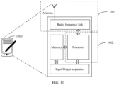
- FIG. 10 is a schematic structural diagram of a terminal device 1000 according to an embodiment of this application.
- the terminal device may perform operations of the first terminal device in the methods shown in FIG. 4 and FIG. 7 , or the terminal device may perform operations of the first terminal device shown in FIG. 8 and FIG. 9 .
- FIG. 10 shows only main components of the terminal device.
- the terminal device 1000 includes a processor, a memory, a radio-frequency link, an antenna, and an input/output apparatus.
- the processor is mainly configured to: process a communications protocol and communication data, control the entire terminal device, execute a software program, and process data of the software program, for example, configured to support the terminal device in executing procedures described in FIG. 4 and FIG. 7 .
- the memory is mainly configured to store a software program and data.
- the radio-frequency link is mainly configured to: convert a baseband signal and a radio frequency signal, and process the radio frequency signal.
- the antenna panel is mainly configured to transmit and receive a radio frequency signal in an electromagnetic wave form.
- the terminal device 1000 may further include the input/output apparatus.
- the input/output apparatus such as a touchscreen, a display screen, or a keyboard, is mainly configured to receive data input by a user and output data to the user. It should be noted that some types of terminal devices may have no input/output apparatus.
- the processor may read a software program in a storage unit, interpret and execute an instruction of the software program, and process data of the software program.
- the processor performs baseband processing on to-be-sent data, and then outputs a baseband signal to a radio-frequency link.
- the radio-frequency link After performing radio frequency processing on the baseband signal, the radio-frequency link sends a radio frequency signal to the outside by using the antenna in an electromagnetic wave form.
- the radio-frequency link receives a radio frequency signal through the antenna, converts the radio frequency signal into a baseband signal, and outputs the baseband signal to the processor.
- the processor converts the baseband signal into data, and processes the data.
- FIG. 10 shows only one memory and one processor.
- An actual terminal device may have a plurality of processors and a plurality of memories.
- the memory may also be referred to as a storage medium, a storage device, or the like. This is not limited in the embodiments of this application.
- the processor may include a baseband processor and a central processing unit (central processing unit, CPU).
- the baseband processor is mainly configured to process a communication protocol and communication data
- the CPU mainly configured to: control the entire terminal device, execute the software program, and process data of the software program.
- the processor may alternatively be a network processor (network processor, NP) or a combination of a CPU and an NP.
- the processor may further include a hardware chip.
- the hardware chip may be an application-specific integrated circuit (application-specific integrated circuit, ASIC), a programmable logic device (programmable logic device, PLD), or a combination thereof.
- the foregoing PLD may be a complex programmable logic device (complex programmable logic device, CPLD), a field programmable gate array (field-programmable gate array, FPGA), a generic array logic (generic array logic, GAL), or any combination thereof.
- the memory may include a volatile memory (volatile memory), for example, a random access memory (random-access memory, RAM).
- the memory may alternatively include a non-volatile memory (non-volatile memory), for example, a flash memory (flash memory), a hard disk drive (hard disk drive, HDD), or a solid-state drive (solid-state drive, SSD).
- flash memory flash memory
- HDD hard disk drive
- SSD solid-state drive
- the memory may alternatively include a combination of the foregoing types of memories.
- the antenna and the radio-frequency link that have sending and receiving functions may be considered as a transceiver unit 1001 of the terminal device 1000, and the processor that has a processing function may be considered as a processing unit 1002 of the terminal device 1000.
- the terminal device 1000 may include a transceiver unit 1001 and a processing unit 1002.
- the transceiver unit may also be referred to as a transceiver, a transceiver machine, a transceiver apparatus, or the like.
- a component for implementing a receiving function in the transceiver unit 1001 may be considered as a receiving unit
- a component for implementing a sending function in the transceiver unit 1001 may be considered as a sending unit. That is, the transceiver unit 1001 includes the receiving unit and the sending unit.
- the receiving unit may also be referred to as a receiver machine, a receiver, a receiver circuit, or the like.
- the sending unit may be referred to as a transmitter machine, a transmitter, a transmitter circuit, or the like.
- the transceiver unit 1001 and the processing unit 1002 may be integrated into one component, or may be separated into different components.
- the processor and the memory may be integrated into one component, or may be separated into different components.
- the transceiver unit 1001 may be configured to perform the method shown in step 402 shown in FIG. 4 .
- the transceiver unit 1001 may be further configured to perform the method shown in step 701 and step 703 shown in FIG. 7 .
- the processing unit 1002 may be configured to control the transceiver unit 1001 to perform the method shown in step 402 shown in FIG. 4 , and the processing unit 1002 may be further configured to control the transceiver unit 1001 to perform the method shown in step 701 and step 703 shown in FIG. 7 .
- the processing unit 1002 may be further configured to perform the method shown in step 401 shown in FIG. 4 and the method shown in step 702 shown in FIG. 7 .
- the transceiver unit 1001 may be further configured to perform the method performed by the sending unit 802 and the receiving unit 803.
- the processing unit 1002 may be further configured to perform the method performed by the processing unit 801.
- An embodiment of this application further provides a computer-readable storage medium. All or some of the procedures in the foregoing method embodiments may be completed by a computer program instructing related hardware.
- the program may be stored in the foregoing computer storage medium. When the program is executed, the procedures in the foregoing method embodiments may be included.
- the computer-readable storage medium may be an internal storage unit of the power control apparatus (including a data transmit end and/or a data receive end) of any one of the foregoing embodiments, for example, a hard disk or memory of the power control apparatus.
- the computer-readable storage medium may be an external storage device of the power control apparatus, for example, a plug-in hard disk, a smart media card (smart media card, SMC), a secure digital (secure digital, SD) card, or a flash card (flash card) that is disposed on the power control apparatus.
- the computer-readable storage medium may include both an internal storage unit and an external storage device of the power control apparatus.
- the computer-readable storage medium is configured to: store the computer program and store other programs and data that are required by the power control apparatus.
- the computer-readable storage medium may be further configured to temporarily store data that has been output or is to be output.
- All or some of the foregoing embodiments may be implemented through software, hardware, firmware, or any combination thereof.
- the embodiments may be implemented completely or partially in a form of a computer program product.
- the computer program product includes one or more computer instructions.
- the computer may be a general-purpose computer, a dedicated computer, a computer network, or another programmable apparatus.
- the computer instructions may be stored in a computer-readable storage medium, or may be transmitted by using the computer-readable storage medium.
- the computer-readable storage medium may be any usable medium accessible by a computer, or a data storage device, such as a server or a data center, integrating one or more usable media.
- the usable medium may be a magnetic medium (for example, a floppy disk, a hard disk, or a magnetic tape), an optical medium (for example, a DVD), a semiconductor medium (for example, a solid-state drive (solid state disk, SSD)), or the like.
- Steps in the method in the embodiments of this application may be adjusted, combined, or deleted according to an actual requirement.
- Modules in the apparatus in the embodiments of this application may be adjusted, combined, or deleted according to an actual requirement.
Landscapes
- Engineering & Computer Science (AREA)
- Computer Networks & Wireless Communication (AREA)
- Signal Processing (AREA)
- Quality & Reliability (AREA)
- Mobile Radio Communication Systems (AREA)
Priority Applications (1)
| Application Number | Priority Date | Filing Date | Title |
|---|---|---|---|
| EP25202875.8A EP4694397A3 (de) | 2018-12-24 | 2019-12-18 | Verfahren und vorrichtung zur leistungsregelung |
Applications Claiming Priority (3)
| Application Number | Priority Date | Filing Date | Title |
|---|---|---|---|
| CN201811588371.0A CN111356220B (zh) | 2018-12-24 | 2018-12-24 | 功率控制方法及装置 |
| EP19902111.4A EP3902338B1 (de) | 2018-12-24 | 2019-12-18 | Leistungssteuerungsverfahren und -vorrichtung |
| PCT/CN2019/126243 WO2020135179A1 (zh) | 2018-12-24 | 2019-12-18 | 功率控制方法及装置 |
Related Parent Applications (2)
| Application Number | Title | Priority Date | Filing Date |
|---|---|---|---|
| EP19902111.4A Division EP3902338B1 (de) | 2018-12-24 | 2019-12-18 | Leistungssteuerungsverfahren und -vorrichtung |
| EP19902111.4A Division-Into EP3902338B1 (de) | 2018-12-24 | 2019-12-18 | Leistungssteuerungsverfahren und -vorrichtung |
Related Child Applications (2)
| Application Number | Title | Priority Date | Filing Date |
|---|---|---|---|
| EP25202875.8A Division-Into EP4694397A3 (de) | 2018-12-24 | 2019-12-18 | Verfahren und vorrichtung zur leistungsregelung |
| EP25202875.8A Division EP4694397A3 (de) | 2018-12-24 | 2019-12-18 | Verfahren und vorrichtung zur leistungsregelung |
Publications (4)
| Publication Number | Publication Date |
|---|---|
| EP4354982A2 true EP4354982A2 (de) | 2024-04-17 |
| EP4354982A3 EP4354982A3 (de) | 2024-07-17 |
| EP4354982C0 EP4354982C0 (de) | 2025-11-05 |
| EP4354982B1 EP4354982B1 (de) | 2025-11-05 |
Family
ID=71129086
Family Applications (3)
| Application Number | Title | Priority Date | Filing Date |
|---|---|---|---|
| EP19902111.4A Active EP3902338B1 (de) | 2018-12-24 | 2019-12-18 | Leistungssteuerungsverfahren und -vorrichtung |
| EP25202875.8A Pending EP4694397A3 (de) | 2018-12-24 | 2019-12-18 | Verfahren und vorrichtung zur leistungsregelung |
| EP23213900.6A Active EP4354982B1 (de) | 2018-12-24 | 2019-12-18 | Verfahren und vorrichtung zur leistungsregelung |
Family Applications Before (2)
| Application Number | Title | Priority Date | Filing Date |
|---|---|---|---|
| EP19902111.4A Active EP3902338B1 (de) | 2018-12-24 | 2019-12-18 | Leistungssteuerungsverfahren und -vorrichtung |
| EP25202875.8A Pending EP4694397A3 (de) | 2018-12-24 | 2019-12-18 | Verfahren und vorrichtung zur leistungsregelung |
Country Status (6)
| Country | Link |
|---|---|
| US (2) | US11825425B2 (de) |
| EP (3) | EP3902338B1 (de) |
| KR (1) | KR102535608B1 (de) |
| CN (3) | CN113225796A (de) |
| ES (1) | ES3053654T3 (de) |
| WO (1) | WO2020135179A1 (de) |
Families Citing this family (7)
| Publication number | Priority date | Publication date | Assignee | Title |
|---|---|---|---|---|
| CN114339978B (zh) * | 2020-09-30 | 2025-04-18 | 展讯通信(上海)有限公司 | 支持prs的侧链功率分配方法及装置、存储介质、终端 |
| CN116326177B (zh) * | 2021-01-07 | 2025-10-10 | Oppo广东移动通信有限公司 | 功率控制的方法、终端设备和网络设备 |
| WO2023028724A1 (zh) * | 2021-08-29 | 2023-03-09 | 富士通株式会社 | 转发器、网络设备及其通信方法 |
| WO2023036040A1 (zh) * | 2021-09-09 | 2023-03-16 | 上海朗帛通信技术有限公司 | 一种被用于无线通信的节点中的方法和装置 |
| JP7718945B2 (ja) * | 2021-09-30 | 2025-08-05 | トヨタ自動車株式会社 | 通信システム、基地局、端末、および通信方法 |
| CN116471651A (zh) * | 2022-01-11 | 2023-07-21 | 华为技术有限公司 | 通信方法和装置 |
| US12509459B2 (en) * | 2024-03-26 | 2025-12-30 | BioAge Labs, Inc. | Inhibitors of NLRP3 inflammasome |
Family Cites Families (11)
| Publication number | Priority date | Publication date | Assignee | Title |
|---|---|---|---|---|
| JP5396427B2 (ja) * | 2011-05-02 | 2014-01-22 | 株式会社Nttドコモ | 無線基地局装置、ユーザ端末装置、無線通信システム、及び無線通信方法 |
| WO2016209056A1 (ko) * | 2015-06-26 | 2016-12-29 | 엘지전자 주식회사 | 무선 통신 시스템에서 장치 대 장치 통신 단말의 신호 송수신 방법 및 장치 |
| ES2871106T3 (es) * | 2015-08-13 | 2021-10-28 | Ntt Docomo Inc | Dispositivo de usuario y método de transmisión de señales |
| JP6865746B2 (ja) * | 2015-10-30 | 2021-04-28 | 華為技術有限公司Huawei Technologies Co.,Ltd. | データ送信方法および装置 |
| US10383147B2 (en) * | 2015-12-28 | 2019-08-13 | Samsung Electronics Co., Ltd. | Methods and apparatus for resource collision avoidance in vehicle to vehicle communication |
| WO2018038565A1 (ko) * | 2016-08-24 | 2018-03-01 | 엘지전자 주식회사 | 무선 통신 시스템에서 v2x 단말에 의해 수행되는 v2x 통신 수행 방법 및 상기 방법을 이용하는 단말 |
| JP6963026B2 (ja) * | 2017-03-24 | 2021-11-05 | エルジー エレクトロニクス インコーポレイティドLg Electronics Inc. | 複数の搬送波が設定された端末の電力割当方法及び上記方法を利用する端末 |
| CN117377046A (zh) * | 2017-05-17 | 2024-01-09 | 华为技术有限公司 | 一种发送和接收指示信息的方法、设备和系统 |
| CN110754051B (zh) * | 2017-06-16 | 2022-04-22 | 索尼公司 | 无线通信装置、基础设施设备和方法 |
| US11153873B2 (en) * | 2018-09-28 | 2021-10-19 | Qualcomm Incorporated | Resolving time-domain resource allocation ambiguity |
| WO2020191559A1 (zh) * | 2019-03-22 | 2020-10-01 | Oppo广东移动通信有限公司 | 传输数据信道的方法和终端设备 |
-
2018
- 2018-12-24 CN CN202110361466.4A patent/CN113225796A/zh active Pending
- 2018-12-24 CN CN201811588371.0A patent/CN111356220B/zh active Active
- 2018-12-24 CN CN202110361672.5A patent/CN113225797B/zh active Active
-
2019
- 2019-12-18 ES ES23213900T patent/ES3053654T3/es active Active
- 2019-12-18 KR KR1020217023576A patent/KR102535608B1/ko active Active
- 2019-12-18 EP EP19902111.4A patent/EP3902338B1/de active Active
- 2019-12-18 EP EP25202875.8A patent/EP4694397A3/de active Pending
- 2019-12-18 WO PCT/CN2019/126243 patent/WO2020135179A1/zh not_active Ceased
- 2019-12-18 EP EP23213900.6A patent/EP4354982B1/de active Active
-
2021
- 2021-06-23 US US17/356,150 patent/US11825425B2/en active Active
-
2023
- 2023-10-20 US US18/491,566 patent/US12200633B2/en active Active
Also Published As
| Publication number | Publication date |
|---|---|
| EP4354982C0 (de) | 2025-11-05 |
| US20220124635A1 (en) | 2022-04-21 |
| CN113225796A (zh) | 2021-08-06 |
| EP4354982B1 (de) | 2025-11-05 |
| ES3053654T3 (en) | 2026-01-23 |
| CN113225797A (zh) | 2021-08-06 |
| CN111356220A (zh) | 2020-06-30 |
| US12200633B2 (en) | 2025-01-14 |
| CN113225797B (zh) | 2022-04-26 |
| WO2020135179A1 (zh) | 2020-07-02 |
| KR102535608B1 (ko) | 2023-05-26 |
| EP3902338A4 (de) | 2022-03-02 |
| CN111356220B (zh) | 2021-04-09 |
| KR20210101324A (ko) | 2021-08-18 |
| EP4694397A3 (de) | 2026-04-08 |
| EP4694397A2 (de) | 2026-02-11 |
| EP4354982A3 (de) | 2024-07-17 |
| US20240064655A1 (en) | 2024-02-22 |
| EP3902338A1 (de) | 2021-10-27 |
| EP3902338B1 (de) | 2024-02-07 |
| US11825425B2 (en) | 2023-11-21 |
Similar Documents
| Publication | Publication Date | Title |
|---|---|---|
| US12200633B2 (en) | Power control method and apparatus | |
| EP3863343B1 (de) | Meldeverfahren und vorrichtung für einen leistungsreservebericht | |
| US20200396690A1 (en) | Data transmission method and terminal device thereof | |
| JPWO2020136855A1 (ja) | ユーザ装置 | |
| US12075390B2 (en) | Transmission resource determining method and apparatus | |
| US12245160B2 (en) | Power control method and power control apparatus | |
| WO2020202483A1 (ja) | ユーザ装置 | |
| CN115136711B (zh) | 通信链路之间的优先化技术 | |
| US12328758B2 (en) | Resource allocation for channel occupancy time sharing in sidelink communication | |
| US11825421B2 (en) | Power control method and apparatus | |
| WO2020221057A1 (zh) | 通信方法和通信装置 | |
| WO2021205664A1 (ja) | 端末及び通信方法 | |
| CN115915407A (zh) | 数据传输方法及装置 | |
| EP4037395A1 (de) | Endgerät und kommunikationsverfahren | |
| EP4468756A1 (de) | Leistungsbestimmungsverfahren und -vorrichtung | |
| WO2021246296A1 (ja) | 端末、通信方法及び通信システム | |
| WO2021192312A1 (ja) | 端末及び通信方法 | |
| CN116438890A (zh) | 侧链路资源选择方法及装置 | |
| CN119906967A (zh) | 一种通信方法及装置 | |
| WO2022085054A1 (ja) | 端末及び通信方法 |
Legal Events
| Date | Code | Title | Description |
|---|---|---|---|
| PUAI | Public reference made under article 153(3) epc to a published international application that has entered the european phase |
Free format text: ORIGINAL CODE: 0009012 |
|
| STAA | Information on the status of an ep patent application or granted ep patent |
Free format text: STATUS: THE APPLICATION HAS BEEN PUBLISHED |
|
| AC | Divisional application: reference to earlier application |
Ref document number: 3902338 Country of ref document: EP Kind code of ref document: P |
|
| AK | Designated contracting states |
Kind code of ref document: A2 Designated state(s): AL AT BE BG CH CY CZ DE DK EE ES FI FR GB GR HR HU IE IS IT LI LT LU LV MC MK MT NL NO PL PT RO RS SE SI SK SM TR |
|
| REG | Reference to a national code |
Ref country code: DE Free format text: PREVIOUS MAIN CLASS: H04W0052380000 Ref country code: DE Ref legal event code: R079 Ref document number: 602019077955 Country of ref document: DE Free format text: PREVIOUS MAIN CLASS: H04W0052380000 Ipc: H04W0052240000 |
|
| PUAL | Search report despatched |
Free format text: ORIGINAL CODE: 0009013 |
|
| AK | Designated contracting states |
Kind code of ref document: A3 Designated state(s): AL AT BE BG CH CY CZ DE DK EE ES FI FR GB GR HR HU IE IS IT LI LT LU LV MC MK MT NL NO PL PT RO RS SE SI SK SM TR |
|
| RIC1 | Information provided on ipc code assigned before grant |
Ipc: H04W 52/38 20090101ALI20240613BHEP Ipc: H04W 52/36 20090101ALI20240613BHEP Ipc: H04W 52/34 20090101ALI20240613BHEP Ipc: H04W 52/28 20090101ALI20240613BHEP Ipc: H04W 52/26 20090101ALI20240613BHEP Ipc: H04W 52/24 20090101AFI20240613BHEP |
|
| STAA | Information on the status of an ep patent application or granted ep patent |
Free format text: STATUS: REQUEST FOR EXAMINATION WAS MADE |
|
| 17P | Request for examination filed |
Effective date: 20250117 |
|
| GRAP | Despatch of communication of intention to grant a patent |
Free format text: ORIGINAL CODE: EPIDOSNIGR1 |
|
| STAA | Information on the status of an ep patent application or granted ep patent |
Free format text: STATUS: GRANT OF PATENT IS INTENDED |
|
| INTG | Intention to grant announced |
Effective date: 20250612 |
|
| RAP3 | Party data changed (applicant data changed or rights of an application transferred) |
Owner name: HUAWEI TECHNOLOGIES CO., LTD. |
|
| GRAS | Grant fee paid |
Free format text: ORIGINAL CODE: EPIDOSNIGR3 |
|
| GRAA | (expected) grant |
Free format text: ORIGINAL CODE: 0009210 |
|
| STAA | Information on the status of an ep patent application or granted ep patent |
Free format text: STATUS: THE PATENT HAS BEEN GRANTED |
|
| AC | Divisional application: reference to earlier application |
Ref document number: 3902338 Country of ref document: EP Kind code of ref document: P |
|
| AK | Designated contracting states |
Kind code of ref document: B1 Designated state(s): AL AT BE BG CH CY CZ DE DK EE ES FI FR GB GR HR HU IE IS IT LI LT LU LV MC MK MT NL NO PL PT RO RS SE SI SK SM TR |
|
| REG | Reference to a national code |
Ref country code: CH Ref legal event code: F10 Free format text: ST27 STATUS EVENT CODE: U-0-0-F10-F00 (AS PROVIDED BY THE NATIONAL OFFICE) Effective date: 20251105 Ref country code: GB Ref legal event code: FG4D |
|
| REG | Reference to a national code |
Ref country code: IE Ref legal event code: FG4D |
|
| U01 | Request for unitary effect filed |
Effective date: 20251105 |
|
| U07 | Unitary effect registered |
Designated state(s): AT BE BG DE DK EE FI FR IT LT LU LV MT NL PT RO SE SI Effective date: 20251112 |
|
| PGFP | Annual fee paid to national office [announced via postgrant information from national office to epo] |
Ref country code: GB Payment date: 20251114 Year of fee payment: 7 |
|
| REG | Reference to a national code |
Ref country code: ES Ref legal event code: FG2A Ref document number: 3053654 Country of ref document: ES Kind code of ref document: T3 Effective date: 20260123 |
|
| U20 | Renewal fee for the european patent with unitary effect paid |
Year of fee payment: 7 Effective date: 20260212 |
|
| PGFP | Annual fee paid to national office [announced via postgrant information from national office to epo] |
Ref country code: ES Payment date: 20260112 Year of fee payment: 7 |
|
| PG25 | Lapsed in a contracting state [announced via postgrant information from national office to epo] |
Ref country code: NO Free format text: LAPSE BECAUSE OF FAILURE TO SUBMIT A TRANSLATION OF THE DESCRIPTION OR TO PAY THE FEE WITHIN THE PRESCRIBED TIME-LIMIT Effective date: 20260205 |
|
| PG25 | Lapsed in a contracting state [announced via postgrant information from national office to epo] |
Ref country code: HR Free format text: LAPSE BECAUSE OF FAILURE TO SUBMIT A TRANSLATION OF THE DESCRIPTION OR TO PAY THE FEE WITHIN THE PRESCRIBED TIME-LIMIT Effective date: 20251105 |
|
| PG25 | Lapsed in a contracting state [announced via postgrant information from national office to epo] |
Ref country code: RS Free format text: LAPSE BECAUSE OF FAILURE TO SUBMIT A TRANSLATION OF THE DESCRIPTION OR TO PAY THE FEE WITHIN THE PRESCRIBED TIME-LIMIT Effective date: 20260205 |
|
| PG25 | Lapsed in a contracting state [announced via postgrant information from national office to epo] |
Ref country code: IS Free format text: LAPSE BECAUSE OF FAILURE TO SUBMIT A TRANSLATION OF THE DESCRIPTION OR TO PAY THE FEE WITHIN THE PRESCRIBED TIME-LIMIT Effective date: 20260305 |
|
| PG25 | Lapsed in a contracting state [announced via postgrant information from national office to epo] |
Ref country code: PL Free format text: LAPSE BECAUSE OF FAILURE TO SUBMIT A TRANSLATION OF THE DESCRIPTION OR TO PAY THE FEE WITHIN THE PRESCRIBED TIME-LIMIT Effective date: 20251105 |