EP4354701A1 - Electronic device and wireless charging method - Google Patents
Electronic device and wireless charging method Download PDFInfo
- Publication number
- EP4354701A1 EP4354701A1 EP22810549.0A EP22810549A EP4354701A1 EP 4354701 A1 EP4354701 A1 EP 4354701A1 EP 22810549 A EP22810549 A EP 22810549A EP 4354701 A1 EP4354701 A1 EP 4354701A1
- Authority
- EP
- European Patent Office
- Prior art keywords
- coil
- electronic device
- angle
- charging
- case
- Prior art date
- Legal status (The legal status is an assumption and is not a legal conclusion. Google has not performed a legal analysis and makes no representation as to the accuracy of the status listed.)
- Pending
Links
- 238000000034 method Methods 0.000 title claims abstract description 61
- 238000004891 communication Methods 0.000 claims description 7
- 238000004590 computer program Methods 0.000 claims description 5
- 238000005516 engineering process Methods 0.000 abstract description 3
- 238000010586 diagram Methods 0.000 description 13
- 230000000694 effects Effects 0.000 description 11
- 238000001514 detection method Methods 0.000 description 5
- 230000006870 function Effects 0.000 description 5
- 230000005540 biological transmission Effects 0.000 description 3
- 238000005452 bending Methods 0.000 description 2
- 230000003287 optical effect Effects 0.000 description 2
- 230000020169 heat generation Effects 0.000 description 1
- 239000004973 liquid crystal related substance Substances 0.000 description 1
- 230000003068 static effect Effects 0.000 description 1
- 230000001052 transient effect Effects 0.000 description 1
Images


Classifications
-
- H—ELECTRICITY
- H02—GENERATION; CONVERSION OR DISTRIBUTION OF ELECTRIC POWER
- H02J—CIRCUIT ARRANGEMENTS OR SYSTEMS FOR SUPPLYING OR DISTRIBUTING ELECTRIC POWER; SYSTEMS FOR STORING ELECTRIC ENERGY
- H02J50/00—Circuit arrangements or systems for wireless supply or distribution of electric power
- H02J50/90—Circuit arrangements or systems for wireless supply or distribution of electric power involving detection or optimisation of position, e.g. alignment
-
- H—ELECTRICITY
- H02—GENERATION; CONVERSION OR DISTRIBUTION OF ELECTRIC POWER
- H02J—CIRCUIT ARRANGEMENTS OR SYSTEMS FOR SUPPLYING OR DISTRIBUTING ELECTRIC POWER; SYSTEMS FOR STORING ELECTRIC ENERGY
- H02J50/00—Circuit arrangements or systems for wireless supply or distribution of electric power
- H02J50/40—Circuit arrangements or systems for wireless supply or distribution of electric power using two or more transmitting or receiving devices
- H02J50/402—Circuit arrangements or systems for wireless supply or distribution of electric power using two or more transmitting or receiving devices the two or more transmitting or the two or more receiving devices being integrated in the same unit, e.g. power mats with several coils or antennas with several sub-antennas
-
- H—ELECTRICITY
- H02—GENERATION; CONVERSION OR DISTRIBUTION OF ELECTRIC POWER
- H02J—CIRCUIT ARRANGEMENTS OR SYSTEMS FOR SUPPLYING OR DISTRIBUTING ELECTRIC POWER; SYSTEMS FOR STORING ELECTRIC ENERGY
- H02J50/00—Circuit arrangements or systems for wireless supply or distribution of electric power
- H02J50/10—Circuit arrangements or systems for wireless supply or distribution of electric power using inductive coupling
-
- H—ELECTRICITY
- H02—GENERATION; CONVERSION OR DISTRIBUTION OF ELECTRIC POWER
- H02J—CIRCUIT ARRANGEMENTS OR SYSTEMS FOR SUPPLYING OR DISTRIBUTING ELECTRIC POWER; SYSTEMS FOR STORING ELECTRIC ENERGY
- H02J50/00—Circuit arrangements or systems for wireless supply or distribution of electric power
- H02J50/005—Mechanical details of housing or structure aiming to accommodate the power transfer means, e.g. mechanical integration of coils, antennas or transducers into emitting or receiving devices
-
- H—ELECTRICITY
- H02—GENERATION; CONVERSION OR DISTRIBUTION OF ELECTRIC POWER
- H02J—CIRCUIT ARRANGEMENTS OR SYSTEMS FOR SUPPLYING OR DISTRIBUTING ELECTRIC POWER; SYSTEMS FOR STORING ELECTRIC ENERGY
- H02J7/00—Circuit arrangements for charging or depolarising batteries or for supplying loads from batteries
- H02J7/0042—Circuit arrangements for charging or depolarising batteries or for supplying loads from batteries characterised by the mechanical construction
-
- H—ELECTRICITY
- H04—ELECTRIC COMMUNICATION TECHNIQUE
- H04M—TELEPHONIC COMMUNICATION
- H04M1/00—Substation equipment, e.g. for use by subscribers
- H04M1/02—Constructional features of telephone sets
- H04M1/0202—Portable telephone sets, e.g. cordless phones, mobile phones or bar type handsets
- H04M1/0206—Portable telephones comprising a plurality of mechanically joined movable body parts, e.g. hinged housings
- H04M1/0208—Portable telephones comprising a plurality of mechanically joined movable body parts, e.g. hinged housings characterized by the relative motions of the body parts
- H04M1/0214—Foldable telephones, i.e. with body parts pivoting to an open position around an axis parallel to the plane they define in closed position
-
- H—ELECTRICITY
- H04—ELECTRIC COMMUNICATION TECHNIQUE
- H04M—TELEPHONIC COMMUNICATION
- H04M1/00—Substation equipment, e.g. for use by subscribers
- H04M1/02—Constructional features of telephone sets
- H04M1/0202—Portable telephone sets, e.g. cordless phones, mobile phones or bar type handsets
- H04M1/0206—Portable telephones comprising a plurality of mechanically joined movable body parts, e.g. hinged housings
- H04M1/0241—Portable telephones comprising a plurality of mechanically joined movable body parts, e.g. hinged housings using relative motion of the body parts to change the operational status of the telephone set, e.g. switching on/off, answering incoming call
- H04M1/0243—Portable telephones comprising a plurality of mechanically joined movable body parts, e.g. hinged housings using relative motion of the body parts to change the operational status of the telephone set, e.g. switching on/off, answering incoming call using the relative angle between housings
Definitions
- This application pertains to the field of wireless charging technologies and specifically relates to an electronic device and a wireless charging method.
- Wireless charging coils are integrated into electronic devices to implement wireless charging for the electronic devices through the wireless charging coils, making charging convenient.
- a folding state of a foldable electronic device is adjustable.
- a position of a wireless charging coil relative to a transmitter coil inside the electronic device varies, and the wireless charging coil may even deviate from the transmitter coil, resulting in poor charging effect.
- Embodiments of this application are intended to provide an electronic device and a wireless charging method, so as to solve the problem of poor charging effect for existing wireless charging.
- an embodiment of this application provides a foldable electronic device, where the electronic device includes a first body, a second body, and charging coils, and the charging coils include a first coil, a second coil, and a third coil; and
- an embodiment of this application provides a wireless charging method performed by a foldable electronic device, where the electronic device includes a first body, a second body, and charging coils, and the charging coils include a first coil, a second coil, and a third coil; the first coil is disposed inside the first body of the electronic device, the second coil is disposed on a first side of the first body of the electronic device and spaced apart from the first coil, and the third coil is disposed on a first side of the second body of the electronic device; and in a case that the electronic device is unfolded, the first side of the first body fits with the first side of the second body; where the method includes:
- an embodiment of this application provides a wireless charging apparatus, where a foldable electronic device corresponding to the wireless charging apparatus includes a first body, a second body, and charging coils, and the charging coils include a first coil, a second coil, and a third coil; the first coil is disposed inside the first body of the electronic device, the second coil is disposed on a first side of the first body of the electronic device and spaced apart from the first coil, and the third coil is disposed on a first side of the second body of the electronic device; and in a case that the electronic device is unfolded, the first side of the first body fits with the first side of the second body; where the wireless charging apparatus includes:
- an embodiment of this application provides an electronic device, where the electronic device includes a processor, a memory, and a program or instructions stored in the memory and capable of running on the processor, and when the program or instructions are executed by the processor, the steps of the method according to the second aspect are implemented.
- an embodiment of this application provides a readable storage medium, where the readable storage medium stores a program or instructions, and when the program or instructions are executed by a processor, the steps of the method according to the second aspect are implemented.
- an embodiment of this application provides a chip, where the chip includes a processor and a communication interface, the communication interface is coupled to the processor, and the processor is configured to run a program or instructions so as to implement the method according to the second aspect.
- an embodiment of this application provides a computer program product, where the program product is stored in a non-volatile storage medium, and the program product is executed by at least one processor so as to implement the method according to the second aspect.
- an embodiment of this application provides an electronic device, where the electronic device is configured to perform the method according to the second aspect.
- the foldable electronic device in the embodiments of this application is provided with the first coil, the second coil, and the third coil.
- the second coil and the third coil work together for charging; and in a case that the folding angle is less than the preset angle, the first coil works for charging.
- a corresponding coil can be used for working based on a folding state of the electronic device to implement charging. Even though the folding angle of the electronic device can be adjusted and changed, a corresponding coil can be selected for charging based on the magnitude of the folding angle, instead of using a same charging coil for charging regardless of the folding state of the electronic device, thereby improving the charging effect.
- first, second, and the like in the specification and claims of this application are used to distinguish between similar objects rather than to describe a specific order or sequence. It should be understood that terms used in this way are interchangeable in appropriate circumstances such that the embodiments of this application can be implemented in an order other than those illustrated or described herein.
- first and second are typically used to distinguish objects of a same type and do not limit quantities of the objects. For example, there may be one or more first objects.
- and/or in the specification and claims represents at least one of connected objects, and the character “/" generally indicates that the contextually associated objects have an "or” relationship.
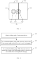
- the electronic device includes a first body 101, a second body 102, and charging coils.
- the charging coils include a first coil 1031, a second coil 1032, and a third coil 1033.
- the first coil 1031 is disposed inside the first body 101 of the electronic device
- the second coil 1032 is disposed on a first side of the first body 101 of the electronic device and spaced apart from the first coil 1031
- the third coil 1033 is disposed on a first side of the second body 102 of the electronic device.
- the first side of the first body 101 fits with the first side of the second body 102; in a case that a folding angle of the electronic device is greater than or equal to a preset angle, the second coil 1032 and the third coil 1033 work together for charging; and in a case that the folding angle of the electronic device is less than the preset angle, the first coil 1031 works for charging.
- the electronic device being unfolded can be understood as the electronic device being fully unfolded, in which case the folding angle of the electronic device is 180°.
- the first side of the first body 101 fits with the first side of the second body 102
- the second coil 1032 is disposed on the first side of the first body 101
- the third coil 1033 is disposed on the first side of the second body 102. Therefore, in the case that the electronic device is unfolded, that is, in the case that the folding angle of the electronic device is 180°, the first side of the first body 101 fits with the first side of the second body 102.
- the folding angle of the electronic device refers to an included angle between surfaces of the two bodies on which screens are provided.
- the preset angle may be an angle preset based on experience, for example, may be preset based on information such as screen size of the electronic device and proportions of screen sizes of a first screen 1011 and a second screen 1021 of the electronic device.
- the first coil 1031 can be used to charge the electronic device, where the first wireless charging coil senses a changing magnetic field generated by a transmitter coil to generate a voltage for charging the electronic device.
- the second coil 1032 and the third coil 1033 can work together to charge the electronic device, where the second coil 1032 and the third coil 1033 sense a changing magnetic field generated by a transmitter coil in a transmitter base to generate a voltage for charging the electronic device.
- the foldable electronic device in this embodiment of this application is provided with the first coil 1031, the second coil 1032, and the third coil 1033.
- the second coil 1032 and the third coil 1033 work together for charging; and in a case that the folding angle is less than the preset angle, the first coil 1031 works for charging.
- a corresponding coil can be used for working based on a folding state of the electronic device to implement charging. Even though the folding angle of the electronic device can be adjusted and changed, a corresponding coil can be selected for charging based on the magnitude of the folding angle, instead of using a same charging coil for charging regardless of the folding state of the electronic device, thereby improving the charging effect.
- the first coil 1031 is located in a central region of the first body 101, and in a case that the folding angle of the electronic device is 180 degrees, a target coil formed by combination of the second coil 1032 and the third coil 1033 is located in a central region of a body formed by fitting of the first body 101 with the second body 102.
- a central position of the electronic device can be opposite a central region of the charger without deviating from the central region, ensuring stable placement of the electronic device on the wireless charger for charging.
- the target coil formed by combination of the second coil 1032 and the third coil 1033 is a circular coil.
- the second coil 1032 and the third coil 1033 can better sense the magnetic field of the transmitter coil, improving the sensing effect, and thereby improving the charging efficiency and the like.
- the target coil is a flexible coil, which means that the target coil can bend along with the folding and bending of the electronic device.
- the target coil can be a complete coil, and the second coil and the third coil can be considered as part of the target coil. This can reduce damage to the target coil caused by the folding and bending of the electronic device, thereby prolonging service life of the target coil.
- this application provides an embodiment of a wireless charging method performed by a foldable electronic device.
- the electronic device includes a first body, a second body, and charging coils.
- the charging coils include a first coil, a second coil, and a third coil.
- the first coil is disposed inside the first body of the electronic device
- the second coil is disposed on a first side of the first body of the electronic device and spaced apart from the first coil
- the third coil is disposed on a first side of the second body of the electronic device.
- the first side of the first body fits with the first side of the second body.
- the method includes the following steps.
- Step 210 Obtain a folding angle of the electronic device.
- the electronic device is a foldable device, and through rotation of at least one of the first body and the second body, the electronic device can be folded, and the folding angle of the foldable electronic device can be changed.
- a range of the folding angle is [0°, 180°].
- the folding angle being 0° indicates that the electronic device is in a fully folded state.
- the folding angle being 180° indicates that the electronic device is in a fully unfolded state, that is, in an unfolded state.
- the folding angle being between 0° and 180° indicates that the electronic device is in a partially unfolded state or a partially folded state.
- the folding angle of the foldable electronic device can be obtained first.
- the folding angle of the electronic device can be detected in various manners, which is not limited in this embodiment.
- the folding angle can be detected in real time or at intervals of preset duration (for example, T, where T > 0).
- Step 220 In a case that the folding angle of the electronic device is less than a preset angle, control the first coil to work for charging.
- the preset angle is an angle preset based on experience, for example, may be preset based on information such as screen size of the electronic device and proportions of screen sizes of a first screen and a second screen of the electronic device.
- the first coil can be controlled to work to charge the electronic device.
- the first coil can be connected to a battery of the electronic device, and the first coil senses a changing magnetic field to generate a voltage for charging the electronic device.
- Step 230 In a case that the folding angle of the electronic device is greater than or equal to the preset angle, control the second coil and the third coil to work together for charging.
- the second coil and the third coil can work together to charge the electronic device, where the second coil and the third coil sense a changing magnetic field together to generate a voltage for charging the electronic device.
- the second coil and the third coil can be connected to a battery of the electronic device, and the second coil and the third coil work together to sense a changing magnetic field to generate a voltage for charging the battery of the electronic device.
- the electronic device is provided with the first coil, the second coil, and the third coil, and the folding angle of the electronic device can be obtained.
- the first coil works to charge the electronic device.
- the folding angle of the electronic device is greater than or equal to the preset angle
- the second coil and the third coil work together to charge the electronic device. Even though the folding angle of the electronic device can be adjusted and changed, a corresponding coil can be selected for charging based on the magnitude of the folding angle, instead of using a same charging coil for charging regardless of the folding state of the electronic device, thereby improving the charging effect.
- the method further includes: in a case that the electronic device is in a charging state and that a change in the folding angle of the electronic device from a first angle to a second angle is detected, controlling a candidate coil to work for charging and outputting prompt information, where the prompt information is used to prompt a user to move the electronic device along a target direction so that the candidate coil is aligned with a transmitter coil.
- the candidate coil includes the second coil and the third coil, or the candidate coil is the first coil.
- the target direction is a direction from the second coil to the first coil or a direction from the first coil to the second coil.
- the folding angle of the electronic device changing from the first angle to the second angle indicates that the folding angle of the electronic device in this case is the second angle.
- the prompt information can be output to prompt the user to move the electronic device.
- the user can move the electronic device according to the prompt information to bring the candidate coil close to the changing magnetic field generated by the transmitter coil in a wireless charger and aligned with the transmitter coil. This allows the candidate coil of the electronic device to more efficiently sense the changing magnetic field to charge the electronic device, thereby improving the wireless charging efficiency.
- the candidate coil includes the second coil and the third coil, and the target direction is the direction from the second coil to the first coil; and if the change in the folding angle of the electronic device from the first angle to the second angle is detected after the second coil and the third coil are controlled to work together for charging, the candidate coil includes the first coil, and the target direction is the direction from the first coil to the second coil.
- the prompt information in a case that the first angle is less than the preset angle and that the second angle is greater than or equal to the preset angle, the prompt information is output, where the target direction is the direction from the second coil to the first coil; or in a case that the first angle is greater than or equal to the preset angle and that the second angle is less than the preset angle, the prompt information is output, where the target direction is the direction from the first coil to the second coil.
- the folding angle of the electronic device changing from the first angle to the second angle indicates that the folding angle of the electronic device in this case is the second angle. If the first angle is less than the preset angle and the second angle is greater than or equal to the preset angle, it indicates that the electronic device changes from a relatively folded state to a relatively unfolded state.
- the prompt information can be output to prompt the user to move the electronic device along the target direction from the second coil to the first coil. The user can move the electronic device to bring the target coil formed by the second coil and the third coil close to the changing magnetic field generated by the transmitter coil in the wireless charger and aligned with the transmitter coil. This allows the second coil and the third coil of the electronic device to work together more efficiently to charge the electronic device, thereby improving the charging efficiency.
- the prompt information can be output to prompt the user to move the electronic device along the target direction from the first coil to the second coil.
- the user can move the electronic device to bring the first coil close to the changing magnetic field generated by the transmitter coil in the wireless charger and aligned with the transmitter coil. This allows the first coil of the electronic device to work more efficiently to charge the electronic device, thereby improving the charging efficiency.
- the prompt information may include a prompt image.
- the prompt image shows a current structural diagram of the simulated electronic device, the simulated first coil, the simulated second coil and third coil, and the target direction. The user can view the content of the prompt diagram and move the electronic device along the target direction, allowing the candidate coil of the electronic device to work more efficiently to charge the electronic device, and thereby improving the charging effect.
- the outputting prompt information includes:
- the received power also needs to satisfy the requirement.
- the prompt information can be output to prompt the user to move the electronic device, allowing the electronic device to be more efficiently charged using a corresponding coil, reducing a frequency of switching between wireless charging coils during charging, and thereby improving the charging efficiency.
- the preset threshold may be a first preset threshold; or if the first angle is greater than or equal to the preset angle and the second angle is less than the preset angle, the preset threshold may be a second preset threshold; where the first preset threshold and the second preset threshold may be different.
- the foldable electronic device being a mobile terminal is used as an example for description, for example, a mobile phone, the mobile phone being a foldable mobile phone.
- the foldable electronic device includes a first body 101, a second body 102, and charging coils 103.
- the charging coils 103 include a first coil 1031, a second coil 1032, and a third coil 1033.
- the first coil 1031 is disposed inside the first body 101 of the electronic device
- the second coil 1032 is disposed on a first side of the first body 101 of the electronic device and spaced apart from the first coil 1031
- the third coil 1033 is disposed on a first side of the second body 102 of the electronic device.
- the first body 101 is provided with a first screen 1011
- the second body 102 is provided with a second screen 1021 and a third screen 1022 facing away from each other.
- the first screen 1011 and the second screen 1021 form a foldable front home screen of the electronic device, which can be folded along the middle rotation axis.
- the front home screen of the mobile phone being fully unfolded is shown in FIG. 3 .
- the middle part of the front home screen is a foldable flexible screen.
- the foldable mobile phone can be placed horizontally or vertically, so its screen can be in landscape or portrait mode.
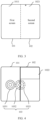
- FIG. 5 shows a structural diagram of the mobile phone in a fully folded state, where the first coil inside the first body may be located in a central region of the first body.
- the first screen 1011 and the second screen 1021 are completely folded, and content can be displayed on the third screen 1022.
- the third screen 1022 is a screen disposed on the back of the mobile phone. Spatial positions of the second coil and the third coil overlap in a direction perpendicular to the screen after folding.
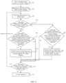
- FIG. 6 is a schematic flowchart of the wireless charging method according to this embodiment. Specific steps are as follows.
- Step 601. Place the foldable mobile phone on a wireless charger.
- a transmitter base in the wireless charger may be placed vertically or horizontally.
- Step 602. Determine a receiving coil for initial wireless charging.
- the foldable mobile phone detects an initial folding angle of the electronic device placed on the wireless charger to determine the initial receiving coil for wireless charging.
- Step 603. The mobile phone detects a folding angle.
- the folding angle is detected at intervals of preset duration T.
- Step 604. Determine whether the folding angle is greater than or equal to the preset angle ⁇ .
- Step 605 Determine whether a difference between received power for wireless charging before the folding operation and received power for wireless charging after the folding operation is greater than a first preset threshold.
- the corresponding received power for wireless charging at the first angle is first received power P1
- the corresponding received power for wireless charging at the second angle for the end state after the folding operation is second received power P2
- the first preset threshold is ⁇ P 1. If P1 - P2 ⁇ ⁇ P 1, which means that it is necessary to prompt the user to switch to the second wireless charging coil for wireless power transmission, proceed to step 607. If P1 - P2 ⁇ ⁇ P1, which means that switching is not needed because the power difference is low, proceed to step 609 to reduce the frequency of switching.
- Step 606 Determine whether a difference between received power for wireless charging before the folding operation and received power for wireless charging after the folding operation is greater than a second preset threshold.
- the corresponding received power for wireless charging at the first angle is first received power P1
- the corresponding received power for wireless charging at the second angle for the end state after the folding operation is second received power P2
- the second preset threshold is ⁇ P2.
- ⁇ P1 and ⁇ P2 are both thresholds for the difference between power before and after folding, with the difference lying in their values, as different power during folding or unfolding leads to different thresholds. If P1 - P2 ⁇ ⁇ P2, which means that it is necessary to prompt the user to switch to the first wireless charging coil for wireless power transmission, proceed to step 608. If P1 - P2 ⁇ ⁇ P2, which means that switching is not needed because the power difference is low, proceed to step 609.
- Step 607 Prompt the user to switch from the first coil to the second coil and the third coil working together for wireless charging.
- a first prompt image is displayed, where direction f1 is a first prompt direction for movement.
- a target direction is the first prompt direction for movement.
- the user can move the mobile phone according to the prompt of direction f1 so that the mobile phone is charged by using the second coil and the third coil working together.
- Step 608 Prompt the user to switch from the second coil and the third coil working together to the first coil for wireless charging.
- a second prompt image is displayed, where direction f2 is a second prompt direction for movement.
- a target direction is the second prompt direction for movement.
- the user can move the mobile phone according to the prompt of direction f2 so that the mobile phone is charged using the first coil.
- Step 609 Determine whether the mobile phone is still in the wireless charging state.
- step 610 If the mobile phone is not in the charging state, proceed to step 610 to exit the detection.
- Step 610 Exit the detection. That is, exit the folding angle detection.
- the user can obtain better experience of wireless charging during use of the foldable mobile phone in the unfolded state, and in a case that the folding angle changes, the user can be prompted and guided to move the electronic device to allow more efficient wireless charging by the wireless charging coil, thereby reducing unnecessary power loss and reducing heat generation while improving the charging efficiency.
- the electronic device in this embodiment of this application may be a mobile device, and the mobile device includes but is not limited to a mobile phone, a tablet computer, or a handheld device.
- the wireless charging method according to this embodiment of this application may be executed by a wireless charging apparatus or a control module for executing the wireless charging method in the wireless charging apparatus.
- the wireless charging method being executed by the wireless charging apparatus is used as an example to describe the wireless charging apparatus according to the embodiments of this application.
- a foldable electronic device corresponding to the wireless charging apparatus includes a first body, a second body, and charging coils.
- the charging coils include a first coil, a second coil, and a third coil.
- the first coil is disposed inside the first body of the electronic device
- the second coil is disposed on a first side of the first body of the electronic device and spaced apart from the first coil
- the third coil is disposed on a first side of the second body of the electronic device.
- the first side of the first body fits with the first side of the second body.
- the wireless charging apparatus 900 includes:
- the apparatus 900 further includes: a processing module configured to: in a case that the electronic device is in a charging state and that a change in the folding angle of the electronic device from a first angle to a second angle is detected, control a candidate coil to work for charging and output prompt information, where the prompt information is used to prompt a user to move the electronic device along a target direction so that the candidate coil is aligned with a transmitting coil.
- a processing module configured to: in a case that the electronic device is in a charging state and that a change in the folding angle of the electronic device from a first angle to a second angle is detected, control a candidate coil to work for charging and output prompt information, where the prompt information is used to prompt a user to move the electronic device along a target direction so that the candidate coil is aligned with a transmitting coil.
- the candidate coil includes the second coil and the third coil, or the candidate coil is the first coil.
- the target direction is a direction from the second coil to the first coil or a direction from the first coil to the second coil.
- the outputting prompt information includes:
- the outputting prompt information includes:
- the wireless charging apparatus in this embodiment of this application may be an apparatus or a component, integrated circuit, or chip in a terminal.
- the apparatus may be a mobile electronic device or a non-mobile electronic device.
- the mobile electronic device may be a mobile phone, a tablet computer, a notebook computer, a palmtop computer, a vehicular electronic device, a wearable device, an ultra-mobile personal computer (ultra-mobile personal computer, UMPC), a netbook, a personal digital assistant (personal digital assistant, PDA), or the like.
- the non-mobile electronic device may be a network attached storage (Network Attached Storage, NAS), a personal computer (personal computer, PC), a television (television, TV), a teller machine, a self-service machine, or the like. This is not specifically limited in the embodiments of this application.
- the wireless charging apparatus in this embodiment of this application may be an apparatus having an operating system.
- the operating system may be an android (Android) operating system, may be an iOS operating system, or may be another possible operating system. This is not specifically limited in the embodiments of this application.
- the wireless charging apparatus provided in this embodiment of this application can implement the processes implemented in the wireless charging method embodiments, for example, can implement the processes implemented in the method embodiments in FIG. 2 and FIG. 6 . To avoid repetition, details are not described herein again.
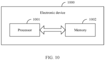
- an embodiment of this application further provides an electronic device 1000 including a processor 1001, a memory 1002, and a program or instructions stored in the memory 1002 and capable of running on the processor 1001, where when the program or instructions are executed by the processor 1001, the processes of the foregoing wireless charging method embodiments are implemented, with the same technical effects achieved. To avoid repetition, details are not described herein again.
- the electronic device in this embodiment of this application includes the above-mentioned mobile electronic device and non-mobile electronic device.
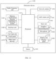
- FIG. 11 is a schematic diagram of a hardware structure of an electronic device according to an embodiment of this application.
- the electronic device 1100 includes but is not limited to components such as a radio frequency unit 1101, a network module 1102, an audio output unit 1103, an input unit 1104, a sensor 1105, a display unit 1106, a user input unit 1107, an interface unit 1108, a memory 1109, and a processor 1110.
- the electronic device 1100 may further include a power supply (for example, battery) that supplies power to various components.
- the power supply may be logically connected to the processor 1110 via a power management system, so that functions such as charge and discharge management and power consumption management are implemented via the power management system.
- the structure of the electronic device shown in FIG. 11 does not constitute a limitation on the electronic device.
- the electronic device may include more or fewer components than shown in the drawing, or combine some of the components, or arrange the components differently. Details are not described herein.
- the electronic device includes a first body, a second body, and charging coils.
- the charging coils include a first coil, a second coil, and a third coil.
- the first coil is disposed inside the first body of the electronic device
- the second coil is disposed on a first side of the first body of the electronic device and spaced apart from the first coil
- the third coil is disposed on a first side of the second body of the electronic device.
- the processor 1110 is configured to: obtain a folding angle of the electronic device; in a case that the folding angle of the electronic device is less than a preset angle, control the first coil to work for charging; and in a case that the folding angle of the electronic device is greater than or equal to the preset angle, control the second coil and the third coil to work together for charging.
- the processor 1110 is configured to: in a case that the electronic device is in a charging state and that a change in the folding angle of the electronic device from a first angle to a second angle is detected, control a candidate coil to work for charging and output prompt information, where the prompt information is used to prompt a user to move the electronic device along a target direction so that the candidate coil is aligned with a transmitting coil.
- the candidate coil includes the second coil and the third coil, or the candidate coil is the first coil.
- the target direction is a direction from the second coil to the first coil or a direction from the first coil to the second coil.
- the outputting prompt information includes:
- the outputting prompt information includes:
- the input unit 1104 may include a graphics processing unit (Graphics Processing Unit, GPU) 11041 and a microphone 11042.
- the graphics processing unit 11041 processes image data of a static picture or a video that is obtained by an image capture apparatus (for example, a camera) in a video capture mode or an image capture mode.
- the display unit 1106 may include a display panel 11061.
- the display panel 11061 may be configured in a form of a liquid crystal display, an organic light-emitting diode display, or the like.
- the user input unit 1107 includes a touch panel 11071 and other input devices 11072.
- the touch panel 11071 is also referred to as a touchscreen.
- the touch panel 11071 may include two parts: a touch detection apparatus and a touch controller.
- the other input devices 11072 may include but are not limited to a physical keyboard, a function button (such as a volume control button or a power on/off button), a trackball, a mouse, and a joystick. Details are not described herein.
- the memory 1109 may be configured to store software programs and various data, including but not limited to application programs and operating systems.
- the processor 1110 may integrate an application processor and a modem processor.
- the application processor mainly processes an operating system, a user interface, an application program, and the like.
- the modem processor mainly processes wireless communication. It can be understood that the modem processor may alternatively be not integrated in the processor 1110.
- An embodiment of this application further provides a readable storage medium, where the readable storage medium stores a program or instructions, and when the program or instructions are executed by a processor, the processes of the foregoing wireless charging method embodiments are implemented, with the same technical effects achieved. To avoid repetition, details are not described herein again.
- the processor is the processor in the electronic device in the foregoing embodiments.
- the readable storage medium includes a computer-readable storage medium, for example, a computer read-only memory (Read-Only Memory, ROM), a random access memory (Random Access Memory, RAM), a magnetic disk, or an optical disc.
- An embodiment of this application further provides a computer program product, where the computer program product is stored in a non-transient readable storage medium, and the computer program product is executed by at least one processor so as to implement the processes of the foregoing wireless charging method embodiments, with the same technical effects achieved. To avoid repetition, details are not described herein again.
- An embodiment of this application further provides a chip, where the chip includes a processor and a communication interface, the communication interface is coupled to the processor, and the processor is configured to run a program or instructions so as to implement the processes of the foregoing wireless charging method embodiments, with the same technical effects achieved. To avoid repetition, details are not described herein again.
- the chip in the embodiments of this application may also be referred to as a system-level chip, a system chip, a chip system, a system on chip, or the like.
- the computer software product is stored in a storage medium (for example, a ROM/RAM, a magnetic disk, or an optical disc), and includes several instructions for instructing a terminal (which may be a mobile phone, a computer, a server, an air conditioner, a network device, or the like) to perform the method described in the embodiments of this application.
- a storage medium for example, a ROM/RAM, a magnetic disk, or an optical disc
- a terminal which may be a mobile phone, a computer, a server, an air conditioner, a network device, or the like
Landscapes
- Engineering & Computer Science (AREA)
- Power Engineering (AREA)
- Computer Networks & Wireless Communication (AREA)
- Signal Processing (AREA)
- Charge And Discharge Circuits For Batteries Or The Like (AREA)
Applications Claiming Priority (2)
| Application Number | Priority Date | Filing Date | Title |
|---|---|---|---|
| CN202110566747.3A CN113541324B (zh) | 2021-05-24 | 2021-05-24 | 电子设备和无线充电方法 |
| PCT/CN2022/094690 WO2022247824A1 (zh) | 2021-05-24 | 2022-05-24 | 电子设备和无线充电方法 |
Publications (1)
| Publication Number | Publication Date |
|---|---|
| EP4354701A1 true EP4354701A1 (en) | 2024-04-17 |
Family
ID=78124381
Family Applications (1)
| Application Number | Title | Priority Date | Filing Date |
|---|---|---|---|
| EP22810549.0A Pending EP4354701A1 (en) | 2021-05-24 | 2022-05-24 | Electronic device and wireless charging method |
Country Status (5)
| Country | Link |
|---|---|
| US (1) | US20240088722A1 (zh) |
| EP (1) | EP4354701A1 (zh) |
| KR (1) | KR20240011812A (zh) |
| CN (1) | CN113541324B (zh) |
| WO (1) | WO2022247824A1 (zh) |
Families Citing this family (2)
| Publication number | Priority date | Publication date | Assignee | Title |
|---|---|---|---|---|
| CN113541324B (zh) * | 2021-05-24 | 2023-02-24 | 维沃移动通信有限公司 | 电子设备和无线充电方法 |
| CN117895614B (zh) * | 2024-01-19 | 2024-08-13 | 深圳市易湘瑞科技有限公司 | 无线可充可放移动电源及其充电的控制方法 |
Family Cites Families (8)
| Publication number | Priority date | Publication date | Assignee | Title |
|---|---|---|---|---|
| TWI454887B (zh) * | 2011-10-31 | 2014-10-01 | Hon Hai Prec Ind Co Ltd | 電子裝置保護套 |
| KR102677576B1 (ko) * | 2019-04-18 | 2024-06-25 | 삼성전자주식회사 | 폴더블 전자 장치의 상태 인식 방법 및 이를 지원하는 폴더블 전자 장치 |
| EP3767776A1 (en) * | 2019-07-16 | 2021-01-20 | Yen Kuang Lee | Protective apparatus for wireless charging |
| KR102695029B1 (ko) * | 2019-10-17 | 2024-08-13 | 삼성전자 주식회사 | 전자 펜을 포함하는 멀티 폴더블 전자 장치 |
| CN111864914B (zh) * | 2020-07-03 | 2022-02-25 | 维沃移动通信有限公司 | 电子设备组件及充电控制方法、电子设备的充电控制装置 |
| CN112671118A (zh) * | 2020-12-08 | 2021-04-16 | Oppo广东移动通信有限公司 | 无线充电设备 |
| CN112636483B (zh) * | 2020-12-09 | 2023-08-04 | 维沃移动通信有限公司 | 无线充电装置及其控制方法、控制装置和电子设备 |
| CN113541324B (zh) * | 2021-05-24 | 2023-02-24 | 维沃移动通信有限公司 | 电子设备和无线充电方法 |
-
2021
- 2021-05-24 CN CN202110566747.3A patent/CN113541324B/zh active Active
-
2022
- 2022-05-24 EP EP22810549.0A patent/EP4354701A1/en active Pending
- 2022-05-24 KR KR1020237044647A patent/KR20240011812A/ko active Search and Examination
- 2022-05-24 WO PCT/CN2022/094690 patent/WO2022247824A1/zh active Application Filing
-
2023
- 2023-11-21 US US18/516,811 patent/US20240088722A1/en active Pending
Also Published As
| Publication number | Publication date |
|---|---|
| WO2022247824A1 (zh) | 2022-12-01 |
| CN113541324A (zh) | 2021-10-22 |
| US20240088722A1 (en) | 2024-03-14 |
| KR20240011812A (ko) | 2024-01-26 |
| CN113541324B (zh) | 2023-02-24 |
Similar Documents
| Publication | Publication Date | Title |
|---|---|---|
| US20240088722A1 (en) | Electronic device and wireless charging method | |
| EP2407869B1 (en) | Mobile terminal and controlling method thereof | |
| KR101667586B1 (ko) | 이동단말기 및 그 제어방법 | |
| EP2662763B1 (en) | Mobile terminal and control method thereof | |
| KR101521219B1 (ko) | 플렉서블 디스플레이를 이용하는 휴대 단말기 및 그 제어방법 | |
| EP2180676B1 (en) | Mobile communication terminal and screen scrolling method thereof | |
| KR101633332B1 (ko) | 단말기 및 그 제어 방법 | |
| KR101799270B1 (ko) | 이동 단말기 및 이것의 터치 인식 방법 | |
| KR20130006757A (ko) | 플렉서블 디스플레이를 구비하는 영상 표시 장치 및 그 제어방법 | |
| KR20110016194A (ko) | 이동단말기 및 그 제어방법 | |
| CN108055392B (zh) | 显示区域调整方法、移动终端及计算机可读存储介质 | |
| CN109947312A (zh) | 一种控制方法及终端设备 | |
| KR20110082359A (ko) | 플렉서블 디스플레이를 구비하는 이동 단말기 및 그 제어방법 | |
| KR101531912B1 (ko) | 터치센서 및 터치 인식방법 | |
| CN108388336B (zh) | 功耗控制方法、装置及计算机可读存储介质 | |
| CN110716686A (zh) | 显示内容的切换方法及电子设备 | |
| KR20110080315A (ko) | 이동 단말기 | |
| KR20130025555A (ko) | 휴대 단말기 및 그 제어 방법 | |
| CN112887579B (zh) | 摄像头模组控制方法、装置及电子设备 | |
| KR20110022217A (ko) | 이동 단말기 및 그 제어 방법 | |
| KR101622216B1 (ko) | 이동 단말기 및 이것의 입력 제어 방법 | |
| KR20140146759A (ko) | 휴대 단말기 및 그 제어 방법 | |
| KR101823479B1 (ko) | 휴대 단말기 및 그 제어 방법 | |
| KR20120113050A (ko) | 이동 단말 장치 및 이의 자동 밝기 조절 방법 | |
| KR101917692B1 (ko) | 이동 단말기 |
Legal Events
| Date | Code | Title | Description |
|---|---|---|---|
| STAA | Information on the status of an ep patent application or granted ep patent |
Free format text: STATUS: THE INTERNATIONAL PUBLICATION HAS BEEN MADE |
|
| PUAI | Public reference made under article 153(3) epc to a published international application that has entered the european phase |
Free format text: ORIGINAL CODE: 0009012 |
|
| STAA | Information on the status of an ep patent application or granted ep patent |
Free format text: STATUS: REQUEST FOR EXAMINATION WAS MADE |
|
| 17P | Request for examination filed |
Effective date: 20231214 |
|
| AK | Designated contracting states |
Kind code of ref document: A1 Designated state(s): AL AT BE BG CH CY CZ DE DK EE ES FI FR GB GR HR HU IE IS IT LI LT LU LV MC MK MT NL NO PL PT RO RS SE SI SK SM TR |
|
| DAV | Request for validation of the european patent (deleted) | ||
| DAX | Request for extension of the european patent (deleted) |