EP4354074B1 - Gun stock with adjustable comb - Google Patents
Gun stock with adjustable comb Download PDFInfo
- Publication number
- EP4354074B1 EP4354074B1 EP23201433.2A EP23201433A EP4354074B1 EP 4354074 B1 EP4354074 B1 EP 4354074B1 EP 23201433 A EP23201433 A EP 23201433A EP 4354074 B1 EP4354074 B1 EP 4354074B1
- Authority
- EP
- European Patent Office
- Prior art keywords
- stock
- comb
- gun
- gun stock
- pin
- Prior art date
- Legal status (The legal status is an assumption and is not a legal conclusion. Google has not performed a legal analysis and makes no representation as to the accuracy of the status listed.)
- Active
Links
Images


Classifications
-
- F—MECHANICAL ENGINEERING; LIGHTING; HEATING; WEAPONS; BLASTING
- F41—WEAPONS
- F41C—SMALLARMS, e.g. PISTOLS, RIFLES; ACCESSORIES THEREFOR
- F41C23/00—Butts; Butt plates; Stocks
- F41C23/14—Adjustable stock or stock parts, i.e. adaptable to personal requirements, e.g. length, pitch, cast or drop
-
- F—MECHANICAL ENGINEERING; LIGHTING; HEATING; WEAPONS; BLASTING
- F41—WEAPONS
- F41C—SMALLARMS, e.g. PISTOLS, RIFLES; ACCESSORIES THEREFOR
- F41C23/00—Butts; Butt plates; Stocks
-
- F—MECHANICAL ENGINEERING; LIGHTING; HEATING; WEAPONS; BLASTING
- F41—WEAPONS
- F41C—SMALLARMS, e.g. PISTOLS, RIFLES; ACCESSORIES THEREFOR
- F41C23/00—Butts; Butt plates; Stocks
- F41C23/06—Stocks or firearm frames specially adapted for recoil reduction
- F41C23/08—Recoil absorbing pads
-
- F—MECHANICAL ENGINEERING; LIGHTING; HEATING; WEAPONS; BLASTING
- F41—WEAPONS
- F41C—SMALLARMS, e.g. PISTOLS, RIFLES; ACCESSORIES THEREFOR
- F41C23/00—Butts; Butt plates; Stocks
- F41C23/16—Forestocks; Handgrips; Hand guards
Definitions
- the present invention relates to a gun stock with an adjustable comb.
- the comb of a firearm in particular of a gun, such as a shotgun or rifle, is the upper part of the stock extending from the grip to the part where the cheekbone rests.
- the aim of the present invention is to provide a gun stock with an adjustable comb, wherein the comb or cheek rest is adjustable in an improved manner with respect to the prior art.
- an object of the invention is to provide a gun stock wherein the comb or cheek rest is adjustable by means of a structure integrated in the stock.
- An important object of the invention is to provide a gun stock with an adjustable comb that can be manufactured at a lower cost with respect to prior art systems.
- a further object of the present invention is to provide a gun stock with an adjustable comb that, due to its particular constructive characteristics, is capable of ensuring the greatest guarantees of reliability and safety in use.
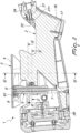
- the gun stock with adjustable comb comprises a stock body 2 provided with an adjustable comb 3.
- the comb 3 comprises a cheek rest member 4 which, by means of a locking screw 61, is associated to a supporting structure 5 in turn associated to the stock body 2.
- the supporting structure 5 comprises a hollow guide body 6, slidable on a pin 7 which is made integral with the stock body 2.
- the guide body 6 is slidable with respect to the pin 7 in contrast with a drive spring 8, coaxial to the pin 7.
- the guide body 6 comprises a set of teeth 9 configured to be engaged by a stop pin 10 by means of lugs 11.
- the stop pin 10 is hollow and contains a limit member 12 coaxial to a contrast spring 13.
- the stop pin 10 comprises a button 14 accessible from the outside of the stock body 2.
- the stop pin 10 further comprises a groove 110 adapted to receive a pin 111.
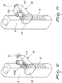
- the height of the comb 4 is adjusted by pressing the button 14 of the stop pin 10 which disengages the teeth 9 of the guide body 6, from the locking position, visible in figure 10 , to the free position, visible in figure 11 , thus allowing the guide body 6, and thus the comb 4, to raise or lower into the desired position, in contrast with the action of the drive spring 8 and the pin 7.
- the adjustable comb structure according to the invention allows such an adjustment to be made with just one hand since, by pressing the button 14, the drive spring 8 is allowed to force the component upwards.
- the user's cheek can be positioned on the comb 4 as it is moved until it reaches the desired height.
- the decompression of the contrast spring 13 allows the lugs 11 of the stop pin 10 to be positioned between the teeth 9 of the guide body 6, thus preventing any vertical movement.
- the system according to the invention allows a very rapid adjustment of the comb 4 without the need to use tools, and further allows it to be adjusted in different positions, each of which is marked on the stock.
- the stop pin 10 is provided with the limit member 12, positioned inside the spring 13, which increases the switching load only during the disassembly step of the comb and not during adjustment.
- Figures 12-14 show three comb positioning examples, respectively in a low position, in an intermediate position, and in a high position.
- the stock 1 comprises an interchangeable grip, identified by the reference number 16.
- the ergonomics of the grip can be modified, offering interchangeable grips fastened to the stock by means of a screw 17 on the lower side of the grip itself, as shown in figures 15 and 16 .
- Figures 17 and 18 show different configurations of the grip, respectively a more inclined grip 161 and a less inclined grip 162.
- the stock 1 further comprises a detachable bag rider 18, as visible in figures 19 and 21 .
- the bag rider 18 can be removed to expose a recess 19 of the stock body 2, as shown in figure 20 .
- the detachable bag rider 18 contributes to the modularity of the stock according to the invention, allowing it to meet to the different needs of the users who can configure the weapon according to their shooting styles and preferences.
- the recess 19 of the stock, without bag rider 18, called "palm hook" is used by many shooters to push, with the hand not used to shoot, the rear part of the weapon towards the shooter's shoulder.
- the recess 19 of the stock carries out a further function, i.e., that of allowing the locking in position of the bag rider 18 and thus its fastening to the stock body 2, simply by mounting the interchangeable grip 16.
- Figure 21 shows the bag rider 18 arranged in the stock body 2 before the grip 16 is fastened.
- Figure 22 shows the fastening system of the stock body 2 to the receiver 20 of the weapon.
- the stock fastening system comprises a screw 21 passing through a recess 22 formed in the stock body 2 and covered by a lid 23.
- the lid 23 has an aesthetic function and allows the user to access the head 211 of the screw 21 by means of a tool, through a small hole 231 of the lid 23.
- the lid 23 is fastened to the stock body 2 by means of a retaining screw 24, accessible through a hole 241 on the opposite side, so as to avoid any clearance and risk of the lid itself falling.
- this system prevents the screw 21 from falling and thus prevents the unintentional loss of useful parts for subsequent assembly.
- the stock 1 further comprises a drop and cast adjustment system.
- the receiver 20 comprises a thread reducer 201 fastened to the receiver itself.
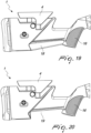
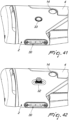
- the LOP adjustment system illustrated in figures 25-37 , comprises buttplates of different thicknesses, identified by the reference numbers 251 and 252.
- the system comprises pairs of spacers comprising a fixed spacer 26 and a movable spacer 27, adapted to operate with a recoil pad device, identified by the reference numeral 28 and visible in figure 2 , of the type described in patent EP2711660B1 , in the name of this same applicant.
- the spacers have been designed so that the fixed spacer 26 is integral with the stock body 2, while, during firing, the movable spacer 27 allows the movable unit of the recoil pad system to freely slide with respect to the stock body 2.
- the user can use various combinations of the above components to achieve the desired configuration.
- Figure 29 shows an example of a buttplate 251 assembled without spacers.
- Figure 30 shows an example of a buttplate 251 assembled with a fixed spacer 26 and a movable spacer 27.
- Figure 31 shows an example of a buttplate 251 assembled with two fixed spacers 26 and two respective movable spacers 27.
- the spacers are assembled incorporated in the comfort recoil pad system ( figures 29-31 ) and there is no risk of losing them while using the shotgun.
- the stock 1 further comprises a system for adjusting the trigger length of pull, i.e., the distance between the grip 16 and the trigger, of the type described in patent US11035644B2 , in the name of this same applicant.
- the position of the stock body 2 with respect to the body of the weapon 20, where the trigger is also located is adjusted by means of the use of special plates 29.
- the user can choose the number and/or thickness of the plates 29 to be assembled, thereby adjusting the trigger length of pull, as visible in figure 39 .
- the stock 1 further comprises an M-Lok ® slot, identified by the reference number 30.
- the M-Lok ® (Modular Lock) system comprises a rod which has a rectangular groove with rounded corners that act as a direct coupling point for compatible accessories.
- the system allows the user to mount any M-Lok ® -compatible accessory such as, for example, a monopod, used as a rear support.
- Figure 40 illustrates the M-Lok ® slot 30 fastened with two screws 31 to the stock body 2.
- the stock 1 further comprises a quick fastener device which allows the user to fasten a quick release sling ring 32, for example; the quick release sling ring 32 interfaces with a metal insert 33 which is located on both sides of the stock body 2.
- the position and profile of the inserts 33 allow both the assembly of any accessories and a 360-degree movement of the rotating part, without interfering with the user himself.
- the invention achieves the intended task and objects, by providing a gun stock with an adjustable comb having an adjustment mechanism integrated in the stock itself.
- the system according to the present invention allows to make a stock with an adjustable comb with a lower industrial cost with respect to the products present on the market.
- An advantage of the present invention is that the stock is designed to be highly modular, so as to meet the various needs of the users who can configure the weapon according to their shooting styles and preferences.
- the bag rider can be removed to expose the stock recess 19.
Landscapes
- Engineering & Computer Science (AREA)
- General Engineering & Computer Science (AREA)
- Aiming, Guidance, Guns With A Light Source, Armor, Camouflage, And Targets (AREA)
- Toys (AREA)
- Coating Apparatus (AREA)
Priority Applications (1)
| Application Number | Priority Date | Filing Date | Title |
|---|---|---|---|
| RS20250523A RS66878B1 (sr) | 2022-10-11 | 2023-10-03 | Kundak sa podesivom obrazinom |
Applications Claiming Priority (1)
| Application Number | Priority Date | Filing Date | Title |
|---|---|---|---|
| IT102022000020964A IT202200020964A1 (it) | 2022-10-11 | 2022-10-11 | Calcio con nasello regolabile, per armi da fuoco |
Publications (2)
| Publication Number | Publication Date |
|---|---|
| EP4354074A1 EP4354074A1 (en) | 2024-04-17 |
| EP4354074B1 true EP4354074B1 (en) | 2025-03-26 |
Family
ID=84943787
Family Applications (1)
| Application Number | Title | Priority Date | Filing Date |
|---|---|---|---|
| EP23201433.2A Active EP4354074B1 (en) | 2022-10-11 | 2023-10-03 | Gun stock with adjustable comb |
Country Status (8)
| Country | Link |
|---|---|
| US (1) | US12270624B2 (pl) |
| EP (1) | EP4354074B1 (pl) |
| CN (1) | CN117870454A (pl) |
| ES (1) | ES3030994T3 (pl) |
| FI (1) | FI4354074T3 (pl) |
| IT (1) | IT202200020964A1 (pl) |
| PL (1) | PL4354074T3 (pl) |
| RS (1) | RS66878B1 (pl) |
Families Citing this family (3)
| Publication number | Priority date | Publication date | Assignee | Title |
|---|---|---|---|---|
| USD1073845S1 (en) * | 2022-10-12 | 2025-05-06 | Benelli Armi S.P.A | Rifle |
| US12281872B2 (en) * | 2022-11-08 | 2025-04-22 | American Tactical, Inc. | Hybrid free-float handguard |
| US12339094B2 (en) * | 2023-10-23 | 2025-06-24 | Axts Inc. | Attaching a grip attachment or other attachment in a recoil environment at threadless region(s) |
Family Cites Families (28)
| Publication number | Priority date | Publication date | Assignee | Title |
|---|---|---|---|---|
| US737732A (en) | 1901-11-12 | 1903-09-01 | Joseph Gaut | Adjustable head-rest for firearms. |
| US1651299A (en) * | 1927-01-26 | 1927-11-29 | Roy V Stansel | Adjustable gunstock |
| US3710496A (en) * | 1970-09-08 | 1973-01-16 | Mershon Co | Firearm adjustable cheek piece |
| US4122623A (en) * | 1977-09-28 | 1978-10-31 | Stice Eldon C | Adjustable gun stock |
| US5031348A (en) * | 1990-10-01 | 1991-07-16 | Carey Donald C | Gun stock assembly with coordinated comb and recoil |
| IT1253058B (it) * | 1991-11-19 | 1995-07-10 | Perazzi Armi Spa | Calcio per fucili con guanciale a posizione regolabile |
| US5970642A (en) * | 1998-01-29 | 1999-10-26 | Martin; Billy B. | Ergonomic adjustable gun stock |
| US6607094B2 (en) | 2001-08-03 | 2003-08-19 | Macdonald Nathan Hollis | Apparatus and method for dispensing medication |
| IL177109A0 (en) | 2005-07-26 | 2007-07-04 | Tdi Arms Ltd | Telescoping stock |
| DE102006059914A1 (de) | 2005-12-23 | 2007-07-05 | Rappenhöner, Hans Richard | Schaft einer Schusswaffe sowie Schaftkappe und Wangenkappe für einen solchen Schaft |
| US7647719B2 (en) * | 2007-01-11 | 2010-01-19 | Magpul Industries Corp. | Gunstocks and adapters |
| DE202009017766U1 (de) | 2009-02-02 | 2010-09-02 | Scherpf, Christian | Schaftbackenverstellung |
| US20100307042A1 (en) * | 2009-06-05 | 2010-12-09 | Michael Brent Jarboe | Modular firearm stock system |
| TWM410210U (en) | 2010-10-29 | 2011-08-21 | Guay Guay Trading Co Ltd | Structure for adjustable butts |
| US8453365B1 (en) | 2012-01-23 | 2013-06-04 | Brookshire Tool & Mfg Co., Inc. | Firearm with movable cheek riser |
| ITMI20121551A1 (it) | 2012-09-19 | 2014-03-20 | Benelli Armi Spa | Dispositivo ammortizzatore del rinculo, per armi da fuoco portatili |
| US8984790B2 (en) | 2013-01-11 | 2015-03-24 | Sig Sauer, Inc. | Adjustable cheek rest |
| RU2546757C1 (ru) | 2014-02-25 | 2015-04-10 | Общество С Ограниченной Ответственностью "Промтехнология" | Механизм регулировки щеки и затылка приклада стрелкового оружия |
| EP3163248B1 (en) | 2015-10-30 | 2018-04-11 | I Chih Shivan Enterprise Co., Ltd. | Buttstock for a gun comprising an adjustable butt member and an adjustable cheek rest |
| USD804602S1 (en) * | 2016-01-12 | 2017-12-05 | Magpul Industries Corp. | Firearm stock |
| US10317165B2 (en) * | 2016-09-15 | 2019-06-11 | Randall J. Saltzman | Modular chassis/stock system for a firearm |
| TR201702475U (tr) | 2017-02-20 | 2017-07-21 | Plasmarket Plastik Ve Metal Kalip Makine Sanayi Ticaret Ltd Sirketi | Teleskobik Dipçik Yanaklık Ayar Mekanizması |
| US10458746B2 (en) | 2017-08-21 | 2019-10-29 | Sig Sauer, Inc. | Adjustable cheek riser |
| NO346779B1 (en) * | 2017-12-29 | 2022-12-27 | GRS Riflestocks AS | A modular stock for a firearm |
| WO2019190439A2 (en) | 2018-03-02 | 2019-10-03 | Plasmarket Plasti̇k Ve Metal Kalip Maki̇ne Sanayi̇ Ti̇caret Li̇mi̇ted Şi̇rketi̇ | Stock with cheek rest and butt adjustment |
| DE102019101228A1 (de) | 2019-01-17 | 2020-07-23 | Blaser Group Gmbh | Vorrichtung zur Verstellung eines Schaftteils an einem Gewehrschaft und Gewehrschaft mit einer derartigen Vorrichtung |
| IT201900007998A1 (it) | 2019-06-04 | 2020-12-04 | Benelli Armi Spa | Calcio per arma |
| US11365952B2 (en) * | 2019-08-16 | 2022-06-21 | Sig Sauer, Inc. | Firearm stock with adjustable butt plate and locking comb assembly |
-
2022
- 2022-10-11 IT IT102022000020964A patent/IT202200020964A1/it unknown
-
2023
- 2023-10-03 EP EP23201433.2A patent/EP4354074B1/en active Active
- 2023-10-03 ES ES23201433T patent/ES3030994T3/es active Active
- 2023-10-03 PL PL23201433.2T patent/PL4354074T3/pl unknown
- 2023-10-03 RS RS20250523A patent/RS66878B1/sr unknown
- 2023-10-03 FI FIEP23201433.2T patent/FI4354074T3/fi active
- 2023-10-09 CN CN202311306340.2A patent/CN117870454A/zh active Pending
- 2023-10-10 US US18/483,583 patent/US12270624B2/en active Active
Also Published As
| Publication number | Publication date |
|---|---|
| US20240118053A1 (en) | 2024-04-11 |
| RS66878B1 (sr) | 2025-07-31 |
| ES3030994T3 (en) | 2025-07-03 |
| EP4354074A1 (en) | 2024-04-17 |
| CN117870454A (zh) | 2024-04-12 |
| FI4354074T3 (fi) | 2025-05-27 |
| PL4354074T3 (pl) | 2025-09-01 |
| IT202200020964A1 (it) | 2024-04-11 |
| US12270624B2 (en) | 2025-04-08 |
Similar Documents
| Publication | Publication Date | Title |
|---|---|---|
| EP4354074B1 (en) | Gun stock with adjustable comb | |
| EP3732431B1 (en) | Modular stock for a firearm | |
| US9410764B2 (en) | Buttstock assembly | |
| US10345074B1 (en) | Firearm chassis system | |
| US7428794B2 (en) | Telescoping stock | |
| US5519954A (en) | Ambidextrous magazine release mechanism for firearms | |
| US7610712B2 (en) | Adjustable rear pistol sight | |
| EP3189295B1 (en) | Automatic adjustable buttstock for small arms | |
| US10591246B2 (en) | Adjusting device for an adjustable rest for a rifle stock | |
| US8156677B2 (en) | Assemblies and firearms incorporating such assemblies | |
| US20160187099A1 (en) | Adjustable length slide-action rifle stock | |
| US10330432B2 (en) | Adjustable firearm stock | |
| US6561073B1 (en) | Device and method for carrying, loading and cocking a firearm | |
| US10876813B2 (en) | Rifle stock mounting rail system | |
| WO2008137187A2 (en) | Semi-automatic and automatic firearm | |
| EA050598B1 (ru) | Ружейный приклад с регулируемым гребнем приклада | |
| US12292256B2 (en) | Adjustable firearm balance weight system |
Legal Events
| Date | Code | Title | Description |
|---|---|---|---|
| PUAI | Public reference made under article 153(3) epc to a published international application that has entered the european phase |
Free format text: ORIGINAL CODE: 0009012 |
|
| STAA | Information on the status of an ep patent application or granted ep patent |
Free format text: STATUS: THE APPLICATION HAS BEEN PUBLISHED |
|
| AK | Designated contracting states |
Kind code of ref document: A1 Designated state(s): AL AT BE BG CH CY CZ DE DK EE ES FI FR GB GR HR HU IE IS IT LI LT LU LV MC ME MK MT NL NO PL PT RO RS SE SI SK SM TR |
|
| STAA | Information on the status of an ep patent application or granted ep patent |
Free format text: STATUS: REQUEST FOR EXAMINATION WAS MADE |
|
| 17P | Request for examination filed |
Effective date: 20240828 |
|
| RBV | Designated contracting states (corrected) |
Designated state(s): AL AT BE BG CH CY CZ DE DK EE ES FI FR GB GR HR HU IE IS IT LI LT LU LV MC ME MK MT NL NO PL PT RO RS SE SI SK SM TR |
|
| GRAP | Despatch of communication of intention to grant a patent |
Free format text: ORIGINAL CODE: EPIDOSNIGR1 |
|
| STAA | Information on the status of an ep patent application or granted ep patent |
Free format text: STATUS: GRANT OF PATENT IS INTENDED |
|
| RIC1 | Information provided on ipc code assigned before grant |
Ipc: F41C 23/14 20060101ALI20241016BHEP Ipc: F41C 23/08 20060101AFI20241016BHEP |
|
| INTG | Intention to grant announced |
Effective date: 20241029 |
|
| GRAS | Grant fee paid |
Free format text: ORIGINAL CODE: EPIDOSNIGR3 |
|
| GRAA | (expected) grant |
Free format text: ORIGINAL CODE: 0009210 |
|
| STAA | Information on the status of an ep patent application or granted ep patent |
Free format text: STATUS: THE PATENT HAS BEEN GRANTED |
|
| AK | Designated contracting states |
Kind code of ref document: B1 Designated state(s): AL AT BE BG CH CY CZ DE DK EE ES FI FR GB GR HR HU IE IS IT LI LT LU LV MC ME MK MT NL NO PL PT RO RS SE SI SK SM TR |
|
| REG | Reference to a national code |
Ref country code: GB Ref legal event code: FG4D |
|
| REG | Reference to a national code |
Ref country code: CH Ref legal event code: EP |
|
| REG | Reference to a national code |
Ref country code: DE Ref legal event code: R096 Ref document number: 602023002594 Country of ref document: DE |
|
| REG | Reference to a national code |
Ref country code: IE Ref legal event code: FG4D |
|
| REG | Reference to a national code |
Ref country code: FI Ref legal event code: FGE |
|
| REG | Reference to a national code |
Ref country code: SE Ref legal event code: TRGR |
|
| REG | Reference to a national code |
Ref country code: ES Ref legal event code: FG2A Ref document number: 3030994 Country of ref document: ES Kind code of ref document: T3 Effective date: 20250703 |
|
| REG | Reference to a national code |
Ref country code: LT Ref legal event code: MG9D |
|
| PG25 | Lapsed in a contracting state [announced via postgrant information from national office to epo] |
Ref country code: HR Free format text: LAPSE BECAUSE OF FAILURE TO SUBMIT A TRANSLATION OF THE DESCRIPTION OR TO PAY THE FEE WITHIN THE PRESCRIBED TIME-LIMIT Effective date: 20250326 |
|
| PG25 | Lapsed in a contracting state [announced via postgrant information from national office to epo] |
Ref country code: LV Free format text: LAPSE BECAUSE OF FAILURE TO SUBMIT A TRANSLATION OF THE DESCRIPTION OR TO PAY THE FEE WITHIN THE PRESCRIBED TIME-LIMIT Effective date: 20250326 |
|
| PG25 | Lapsed in a contracting state [announced via postgrant information from national office to epo] |
Ref country code: BG Free format text: LAPSE BECAUSE OF FAILURE TO SUBMIT A TRANSLATION OF THE DESCRIPTION OR TO PAY THE FEE WITHIN THE PRESCRIBED TIME-LIMIT Effective date: 20250326 |
|
| REG | Reference to a national code |
Ref country code: NL Ref legal event code: MP Effective date: 20250326 |
|
| PG25 | Lapsed in a contracting state [announced via postgrant information from national office to epo] |
Ref country code: NL Free format text: LAPSE BECAUSE OF FAILURE TO SUBMIT A TRANSLATION OF THE DESCRIPTION OR TO PAY THE FEE WITHIN THE PRESCRIBED TIME-LIMIT Effective date: 20250326 |
|
| REG | Reference to a national code |
Ref country code: GR Ref legal event code: EP Ref document number: 20250401127 Country of ref document: GR Effective date: 20250707 |
|
| PG25 | Lapsed in a contracting state [announced via postgrant information from national office to epo] |
Ref country code: SM Free format text: LAPSE BECAUSE OF FAILURE TO SUBMIT A TRANSLATION OF THE DESCRIPTION OR TO PAY THE FEE WITHIN THE PRESCRIBED TIME-LIMIT Effective date: 20250326 |
|
| PG25 | Lapsed in a contracting state [announced via postgrant information from national office to epo] |
Ref country code: PT Free format text: LAPSE BECAUSE OF FAILURE TO SUBMIT A TRANSLATION OF THE DESCRIPTION OR TO PAY THE FEE WITHIN THE PRESCRIBED TIME-LIMIT Effective date: 20250728 |
|
| PGFP | Annual fee paid to national office [announced via postgrant information from national office to epo] |
Ref country code: FI Payment date: 20250923 Year of fee payment: 3 |
|
| PGFP | Annual fee paid to national office [announced via postgrant information from national office to epo] |
Ref country code: GR Payment date: 20250923 Year of fee payment: 3 |
|
| PGFP | Annual fee paid to national office [announced via postgrant information from national office to epo] |
Ref country code: TR Payment date: 20250924 Year of fee payment: 3 Ref country code: PL Payment date: 20250925 Year of fee payment: 3 |
|
| PGFP | Annual fee paid to national office [announced via postgrant information from national office to epo] |
Ref country code: BE Payment date: 20250923 Year of fee payment: 3 |
|
| PGFP | Annual fee paid to national office [announced via postgrant information from national office to epo] |
Ref country code: FR Payment date: 20250923 Year of fee payment: 3 |
|
| PGFP | Annual fee paid to national office [announced via postgrant information from national office to epo] |
Ref country code: SE Payment date: 20250924 Year of fee payment: 3 |
|
| PG25 | Lapsed in a contracting state [announced via postgrant information from national office to epo] |
Ref country code: EE Free format text: LAPSE BECAUSE OF FAILURE TO SUBMIT A TRANSLATION OF THE DESCRIPTION OR TO PAY THE FEE WITHIN THE PRESCRIBED TIME-LIMIT Effective date: 20250326 |
|
| PGFP | Annual fee paid to national office [announced via postgrant information from national office to epo] |
Ref country code: CZ Payment date: 20250909 Year of fee payment: 3 Ref country code: IE Payment date: 20250924 Year of fee payment: 3 Ref country code: RS Payment date: 20250924 Year of fee payment: 3 |
|
| PGFP | Annual fee paid to national office [announced via postgrant information from national office to epo] |
Ref country code: RO Payment date: 20250930 Year of fee payment: 3 |
|
| PG25 | Lapsed in a contracting state [announced via postgrant information from national office to epo] |
Ref country code: SK Free format text: LAPSE BECAUSE OF FAILURE TO SUBMIT A TRANSLATION OF THE DESCRIPTION OR TO PAY THE FEE WITHIN THE PRESCRIBED TIME-LIMIT Effective date: 20250326 |
|
| PG25 | Lapsed in a contracting state [announced via postgrant information from national office to epo] |
Ref country code: IS Free format text: LAPSE BECAUSE OF FAILURE TO SUBMIT A TRANSLATION OF THE DESCRIPTION OR TO PAY THE FEE WITHIN THE PRESCRIBED TIME-LIMIT Effective date: 20250726 |
|
| PGFP | Annual fee paid to national office [announced via postgrant information from national office to epo] |
Ref country code: DE Payment date: 20250923 Year of fee payment: 3 |
|
| PGFP | Annual fee paid to national office [announced via postgrant information from national office to epo] |
Ref country code: NO Payment date: 20251001 Year of fee payment: 3 |
|
| PG25 | Lapsed in a contracting state [announced via postgrant information from national office to epo] |
Ref country code: DK Free format text: LAPSE BECAUSE OF FAILURE TO SUBMIT A TRANSLATION OF THE DESCRIPTION OR TO PAY THE FEE WITHIN THE PRESCRIBED TIME-LIMIT Effective date: 20250326 |
|
| PGFP | Annual fee paid to national office [announced via postgrant information from national office to epo] |
Ref country code: AT Payment date: 20260113 Year of fee payment: 3 |
|
| PGFP | Annual fee paid to national office [announced via postgrant information from national office to epo] |
Ref country code: IT Payment date: 20251031 Year of fee payment: 3 |
|
| PGFP | Annual fee paid to national office [announced via postgrant information from national office to epo] |
Ref country code: ES Payment date: 20251224 Year of fee payment: 3 |
|
| PLBE | No opposition filed within time limit |
Free format text: ORIGINAL CODE: 0009261 |
|
| STAA | Information on the status of an ep patent application or granted ep patent |
Free format text: STATUS: NO OPPOSITION FILED WITHIN TIME LIMIT |
|
| REG | Reference to a national code |
Ref country code: CH Ref legal event code: L10 Free format text: ST27 STATUS EVENT CODE: U-0-0-L10-L00 (AS PROVIDED BY THE NATIONAL OFFICE) Effective date: 20260211 |