EP4354024A1 - Procédé de commande d'un dispositif d'évacuation de vapeurs de cuisson, en particulier pour commander une hotte de cuisson, dispositif de commande, dispositif de cuisson et système de table de cuisson - Google Patents
Procédé de commande d'un dispositif d'évacuation de vapeurs de cuisson, en particulier pour commander une hotte de cuisson, dispositif de commande, dispositif de cuisson et système de table de cuisson Download PDFInfo
- Publication number
- EP4354024A1 EP4354024A1 EP23202786.2A EP23202786A EP4354024A1 EP 4354024 A1 EP4354024 A1 EP 4354024A1 EP 23202786 A EP23202786 A EP 23202786A EP 4354024 A1 EP4354024 A1 EP 4354024A1
- Authority
- EP
- European Patent Office
- Prior art keywords
- fan
- control signal
- operating state
- signal
- control
- Prior art date
- Legal status (The legal status is an assumption and is not a legal conclusion. Google has not performed a legal analysis and makes no representation as to the accuracy of the status listed.)
- Pending
Links
- 238000010411 cooking Methods 0.000 title claims abstract description 62
- 239000003517 fume Substances 0.000 title claims abstract description 50
- 238000000034 method Methods 0.000 title claims abstract description 35
- 238000005259 measurement Methods 0.000 claims abstract description 79
- 238000007620 mathematical function Methods 0.000 claims description 9
- 238000010438 heat treatment Methods 0.000 claims description 5
- 230000006870 function Effects 0.000 description 21
- 230000001276 controlling effect Effects 0.000 description 17
- 238000000605 extraction Methods 0.000 description 17
- 238000009434 installation Methods 0.000 description 15
- 230000007423 decrease Effects 0.000 description 5
- 238000005265 energy consumption Methods 0.000 description 5
- 238000004590 computer program Methods 0.000 description 4
- 230000001419 dependent effect Effects 0.000 description 4
- 239000004519 grease Substances 0.000 description 4
- 238000011144 upstream manufacturing Methods 0.000 description 4
- OKTJSMMVPCPJKN-UHFFFAOYSA-N Carbon Chemical class [C] OKTJSMMVPCPJKN-UHFFFAOYSA-N 0.000 description 3
- 230000006698 induction Effects 0.000 description 3
- 230000005855 radiation Effects 0.000 description 3
- 229920006395 saturated elastomer Polymers 0.000 description 3
- 241001122767 Theaceae Species 0.000 description 2
- 230000003213 activating effect Effects 0.000 description 2
- 238000007664 blowing Methods 0.000 description 2
- 239000007789 gas Substances 0.000 description 2
- 230000005484 gravity Effects 0.000 description 2
- 238000012423 maintenance Methods 0.000 description 2
- 238000011056 performance test Methods 0.000 description 2
- 238000012545 processing Methods 0.000 description 2
- 230000001105 regulatory effect Effects 0.000 description 2
- 238000013459 approach Methods 0.000 description 1
- 230000006399 behavior Effects 0.000 description 1
- 230000033228 biological regulation Effects 0.000 description 1
- 238000001514 detection method Methods 0.000 description 1
- 230000007613 environmental effect Effects 0.000 description 1
- 239000002241 glass-ceramic Substances 0.000 description 1
- 230000001771 impaired effect Effects 0.000 description 1
- 238000003780 insertion Methods 0.000 description 1
- 230000037431 insertion Effects 0.000 description 1
- 230000002123 temporal effect Effects 0.000 description 1
- 230000000007 visual effect Effects 0.000 description 1
Images

Classifications
-
- F—MECHANICAL ENGINEERING; LIGHTING; HEATING; WEAPONS; BLASTING
- F24—HEATING; RANGES; VENTILATING
- F24C—DOMESTIC STOVES OR RANGES ; DETAILS OF DOMESTIC STOVES OR RANGES, OF GENERAL APPLICATION
- F24C15/00—Details
- F24C15/20—Removing cooking fumes
- F24C15/2021—Arrangement or mounting of control or safety systems
-
- F—MECHANICAL ENGINEERING; LIGHTING; HEATING; WEAPONS; BLASTING
- F04—POSITIVE - DISPLACEMENT MACHINES FOR LIQUIDS; PUMPS FOR LIQUIDS OR ELASTIC FLUIDS
- F04D—NON-POSITIVE-DISPLACEMENT PUMPS
- F04D25/00—Pumping installations or systems
- F04D25/02—Units comprising pumps and their driving means
- F04D25/08—Units comprising pumps and their driving means the working fluid being air, e.g. for ventilation
-
- F—MECHANICAL ENGINEERING; LIGHTING; HEATING; WEAPONS; BLASTING
- F04—POSITIVE - DISPLACEMENT MACHINES FOR LIQUIDS; PUMPS FOR LIQUIDS OR ELASTIC FLUIDS
- F04D—NON-POSITIVE-DISPLACEMENT PUMPS
- F04D27/00—Control, e.g. regulation, of pumps, pumping installations or pumping systems specially adapted for elastic fluids
- F04D27/004—Control, e.g. regulation, of pumps, pumping installations or pumping systems specially adapted for elastic fluids by varying driving speed
-
- F—MECHANICAL ENGINEERING; LIGHTING; HEATING; WEAPONS; BLASTING
- F04—POSITIVE - DISPLACEMENT MACHINES FOR LIQUIDS; PUMPS FOR LIQUIDS OR ELASTIC FLUIDS
- F04D—NON-POSITIVE-DISPLACEMENT PUMPS
- F04D29/00—Details, component parts, or accessories
- F04D29/26—Rotors specially for elastic fluids
- F04D29/28—Rotors specially for elastic fluids for centrifugal or helico-centrifugal pumps for radial-flow or helico-centrifugal pumps
- F04D29/281—Rotors specially for elastic fluids for centrifugal or helico-centrifugal pumps for radial-flow or helico-centrifugal pumps for fans or blowers
Definitions
- the invention relates to a method for controlling a device for extracting cooking fumes, in particular for controlling a cooktop extractor.
- the invention also relates to a control device for controlling a device for extracting cooking fumes, in particular for controlling a cooktop extractor.
- the invention also relates to a device with such a control device and a cooktop system with such a device.
- a method for controlling a device for extracting cooking fumes is known.
- a control signal for operating a fan of the device is determined based on a proportional relationship between the volume flow and a speed of the fan.
- the proportional relationship only applies to an ideal system.
- the volume flow delivered by the device therefore differs from the predetermined volume flow, the energy consumption of the device is increased and the user-friendliness of the device is impaired by increased noise emissions.
- a second operating state of a fan for conveying cooking fumes can be set particularly precisely if a second control signal for operating the fan in the second operating state is determined using a first control signal, a first measurement signal and fan characteristics, the fan characteristics comprising the operating states of the fan present for various control signals and for various measurement signals. Because the first measurement signal resulting from the first control signal is taken into account when determining the second control signal, the second operating state of the fan to be brought about with the second control signal can be achieved particularly reliably and precisely, in particular the operating conditions actually present in the device can be taken into account, in particular a momentary flow resistance of the device that varies over time can be taken into account.
- the fan characteristics comprise the operating states of the fan present for several control signals and for several measurement signals
- the second control signal intended to bring about the second operating state can be determined precisely in a wide range of different operating conditions.
- the second operating state is preferably an operating state to which the fan, in particular the device for extracting cooking fumes, is to be set, in particular a target operating state.
- the first operating state preferably differs from the second operating state.
- the second operating state is set based on the second control signal.
- the first operating state is set based on the first control signal.
- the operating state preferably corresponds to the extraction performance of the device, in particular the fan.
- the operating state can correlate with a pressure, in particular in a flow channel of the device and/or at an inflow opening of the device and/or at an outflow opening of the device, and/or with a pressure difference, in particular between the inflow opening and the outflow opening and/or across the fan, and/or with a speed of the fan, in particular a fan motor and/or a fan wheel, and/or with a performance of the fan, in particular an electrical power consumed by the fan motor.
- This advantageously ensures that the extraction of cooking fumes can be set particularly precisely to a target value. This reliably ensures the desired extraction performance and avoids excessive energy consumption and excessive noise emissions.
- the control signal is understood to be a signal for controlling the fan.
- the first control signal preferably differs from the second control signal.
- the second control signal is designed to bring about the second operating state, in particular the target operating state, of the fan, in particular the device.
- the device, in particular the fan can be designed to set the operating state based on the control signal.
- the device, in particular the fan can have an interface for receiving the control signal.
- the interface is preferably a data interface, in particular a wired data interface, and/or a power interface.
- the control signal can be a digital signal and/or a power signal.
- the control signal can set a speed of the fan, in particular the fan motor and/or the fan wheel, and/or the electrical power supplied to the fan motor, in particular correspond to this.
- the control signal preferably corresponds to a speed to be achieved and/or an electrical power actually supplied to the fan motor.
- the respective measurement signal preferably correlates with the respective operating state, in particular with the pressure and/or the pressure difference and/or the volume flow caused by the fan, and/or with the speed of the fan and/or with the electrical power supplied to the fan.
- the measurement signal can be a digital or analog signal.
- the measurement signal is preferably determined in that it is dependent on a predetermined control signal, in particular variable, in relation to different installation situations of the fan, in particular dependent on a flow resistance connected upstream and/or downstream of the fan. This advantageously ensures that the measurement signal includes information about the actual operating state, in particular the extraction performance, of the device, in particular the fan. This allows the extraction performance of the device to be adjusted taking into account the actual installation situation of the fan.
- Correlating information in particular signals, in particular measurement signals correlating with the operating state of the fan, are if there is a definable, in particular a mathematically describable, relationship between this information, in particular if there is a known, for example a proportional, relationship between this information.
- the correlating information can correspond to one another.
- the measurement signal and the operating state are different, in particular they relate to different state variables for describing the operating properties of the device, in particular of the fan.
- the first control signal is preferably a predetermined control signal, in particular a control signal that is predetermined, in particular approximately, to bring about the second operating state.
- a difference can arise between the first operating state brought about by the first control signal and the second operating state, in particular the target operating state.
- the second control signal is preferably determined in relation to the first control signal in such a way that the difference between the first operating state and the second operating state, in particular the target operating state, is reduced, in particular becomes zero.
- the device in particular the at least one fan, can be designed to be operated based on power levels, in particular those selectable by a user.
- Each power level of the fan, in particular of the device can be assigned a target operating state, to which a predetermined first control signal is preferably assigned.
- a target operating state and a first control signal are predetermined for a plurality of adjustable power levels.
- the first control signal can be assigned to the respective target operating state and/or the respective power level in an unchangeable or changeable manner.
- the first control signal assigned to a specific power level and/or a specific target operating state can be changed, in particular replaced, in particular overwritten in a memory unit, preferably by the second control signal, which correlates in particular with the second operating state, in particular the target operating state.
- the fan is preferably a component of a device for extracting cooking fumes.
- the fan can be connected to a flow channel of the device, in particular during operation of the fan based on the first control signal and/or during detection of the first measurement signal correlating with the first operating state of the fan.
- the fan characteristics include status data of the fan in several, in particular in at least two, in particular in at least 10, in particular in at least 15, in particular in at least 20, operating points of the fan.
- the status data preferably include the control signal and the measurement signal and the operating state in the respective operating point, in particular the status data consists of these.
- An operating point is understood to be a state of the fan in which the status data converge, in particular do not change over time, in particular in that with a constant control signal the measuring signal and the operating state are constant, in particular are constant over time.
- the fan characteristics include the status data, in particular the control signal and/or the measurement signal and/or the operating state, at the respective operating point, preferably for different flow resistances acting on the fan, in particular flow resistances upstream and/or downstream of the fan.
- the fan characteristics correspond to a fan characteristic and/or a fan characteristic map.
- the fan characteristics preferably relate the resulting operating state to the underlying control signal and/or to the measurement signal associated with the respective operating state.
- the fan characteristics include the status data for different operating points.
- the operating points preferably comprise the operating states resulting for constant control signals at different flow resistances.
- the fan characteristics preferably comprise the status data for a specific control signal for at least two, in particular at least three, in particular at least four, in particular at least five, in particular at least eight, in particular at least 10, and/or a maximum of 50 flow resistances of the fan.
- An operating point of the fan described by the fan characteristics is preferably determined when the fan is operating without resistance, in particular when the fan is freely sucking in and freely blowing out.
- a further operating point can be determined for a fan whose intake opening and/or blowing out opening is completely blocked.
- the fan characteristics include the status data for different, in particular at least two, in particular at least four, in particular at least six, in particular at least eight, and/or a maximum of 20, control signals.
- the fan characteristics preferably include the status data for a number of operating points which corresponds to the product of the number of different control signals and the number of different flow resistances.
- the fan characteristics contain information about the operating states of the fan resulting from different control signals at different flow resistances.
- the measurement signal preferably correlates with the flow resistance of the device, in particular the fan. Such a measurement signal can, for example, correlate with the speed of the fan, in particular the fan motor and/or the fan wheel, and/or the electrical power supplied to the fan, in particular correspond to these.
- a cooktop extractor is understood to mean a device for extracting cooking fumes downwards.
- the inflow opening of the device in particular the cooktop extractor, preferably penetrates a food support, in particular a cooktop plate, of a cooktop.
- the inflow opening can be completely surrounded by the food support, in particular the cooktop plate.
- the inflow opening is preferably arranged parallel to a cooktop plane, in particular in the cooktop plane.
- the inflow opening is preferably oriented horizontally, in particular oriented vertically downwards to extract cooking fumes.
- the inflow opening can overlap a geometric center of gravity of the cooktop in a plan view, in particular in an orthogonal projection onto the cooktop plane.
- a characteristic value is determined based on the first control signal and/or the first measurement signal, which correlates with the throttling state of the fan or with the air resistance of the at least one flow channel connected to the fan and/or with the installation situation of the fan.
- the characteristic value can be evaluated in particular to determine whether there is a good installation situation with low air resistance, an installation situation that is still sufficient and/or an inadequate installation situation, with too high air resistance or with too high throttling of the fan.
- the characteristic value is also referred to below as the device characteristic value.
- the device characteristic value and/or the first control signal and/or the first measurement signal can be transmitted, in particular retrieved, via a network, in particular via the Internet, in particular for remote maintenance.
- these can be transmitted to a computer program product, in particular to a computer app and/or a mobile device app.
- the computer program product can be designed to determine the quality of the installation situation based on the device characteristic value and/or the first control signal and/or the first measurement signal and/or to output it to the service personnel and/or the user via a suitable user interface, in particular to display it on a display.
- a message about the quality of the installation situation can be sent when the extractor device is first put into operation and/or when the flow resistance changes during operation, for example due to a object, especially a tea towel. This allows the cause of insufficient exhaust air to be identified and eliminated quickly and cost-effectively.
- the volume flow conveyed and/or the power level can be set automatically, in particular by means of a suitably designed control device, depending on which cookware is being used, which recipe is being cooked, in particular what is currently being displayed to the user, and/or what temperature the cookware is at.
- the cookware can be designed with sensors, in particular with temperature sensors and/or with pressure sensors, and/or with a radio module for transmitting information between the cookware and a control device of the extractor hood.
- the operating state in particular the first operating state and/or the second operating state, comprises a volume flow conveyed by the fan, in particular the operating state corresponds to the volume flow.
- the fan characteristics comprise the operating state, in particular the volume flow, preferably for the different control signals and/or the different throttle states of the fan.
- the volume flow is particularly important for the resulting extraction performance of the device. Because the second control signal is designed to bring about the second operating state present as a volume flow, the extraction performance can be set particularly precisely and reliably.
- the measurement signal correlates with a speed of the fan and/or with an electrical power supplied to the fan and/or with a pressure difference caused by the fan, in particular a pressure difference generated by the fan.
- a speed sensor and/or a power sensor and/or a pressure sensor can be provided to detect the measurement signal.
- the measurement signal preferably correlates with a throttle state of the fan, in particular a flow resistance arranged in particular in the device, in particular in the flow channel, in particular upstream and/or downstream of the fan.
- the speed can be the speed of the fan motor and/or the fan wheel.
- the electrical power supplied to the fan is preferably the electrical power consumed by the fan motor.
- the pressure difference is preferably determined as the pressure difference generated by the fan, in particular the difference between the total pressures and/or the absolute pressures, in particular between an area immediately before the fan and an area immediately after the fan.
- the control signal corresponds to a signal for power control by means of pulse width modulation, in particular the ratio of a pulse duration and a pulse period duration.
- the control signal can be a PWM signal.
- the control signal can be a power signal for transmitting the electrical power required to operate the fan.
- the control signal is an information signal which is designed to transmit information, but not to supply the fan with electrical power.
- the control signal differs from the measurement signal.
- the control signal is specified for operating the fan.
- the measurement signal results from the operating point of the fan, which is set depending on the control signal and/or the operating conditions.
- the measurement signal is particularly dependent on the throttle state of the fan, in particular the flow resistance of the device.
- the first operating state is determined based on the combination of the first control signal and the first measurement signal, in particular by means of the fan characteristics. Determining the first operating state enables the determination of a deviation of the first operating state from the second operating state, in particular the target operating state. This makes it possible to deduce the second control signal for bringing about the second operating state, in particular the target operating state. Because the first operating state is determined taking into account the first measurement signal, the first operating state can be determined particularly precisely, in particular taking into account the throttle state of the fan, in particular taking into account the flow resistance of the device.
- the operating state is controlled based on the control signal, the measurement signal and the fan characteristics.
- the second control signal for controlling the fan to the second operating state is determined based on the first operating state.
- the operating state preferably forms the controlled variable.
- the controlled variable can be determined based on the first control signal, the first measurement signal and the fan characteristics.
- the control signal preferably forms the manipulated variable. The difference between the current operating state, in particular the first operating state, in particular the actual operating state, and the desired operating state, in particular the second operating state, in particular the target operating state, can be determined.
- a new control signal in particular the second control signal, can be determined, which is designed to bring about the second operating state, in particular the target operating state.
- the control can be designed as a P controller or as a PI controller or as a PD controller or as a PID controller. This advantageously ensures that the second operating state, in particular the target operating state, can be reliably achieved even under unknown, in particular changing, operating conditions.
- a device characteristic value correlating with the flow resistance of the device is determined based on the combination of the first control signal and the first measurement signal.
- the device characteristic value preferably corresponds to the flow resistance. Due to the dependence of the measurement signal on the flow resistance, the device characteristic value can be reliably determined.
- the measurement signal preferably corresponds to the speed and/or the electrical power supplied to the fan and/or the pressure difference.
- the device characteristic value, in particular the flow resistance can be different, in particular variable, over time, in particular for different operating conditions, in particular installation situations, of the device, in particular the fan.
- the second control signal for bringing about the second operating state can preferably be determined based on the device characteristic value.
- the determination of the second control signal during operation of the fan is repeated, in particular repeated automatically, in particular at predetermined time intervals, in particular with a repetition rate of at least 0.01 Hz, in particular at least 0.1 Hz, in particular 1 Hz.
- the determination of the second control signal during operation of the fan can be continuous and/or initiated by one, in particular each, selection of a power level for operating the device by the user.
- the method for controlling the device for extracting cooking fumes is carried out repeatedly in an automated manner such that the second operating state gradually, in particular iteratively, approaches the target operating state.
- a new first measurement signal can be recorded for this purpose, which correlates with the first operating state of the fan.
- a new second control signal for bringing about the second operating state can be determined based on the new first control signal, the new first measurement signal and the fan characteristics.
- the original second control signal can be used as the new first control signal.
- the fan can be operated based on the new second control signal.
- the method is preferably continued continuously based on the above iterative procedure.
- the fan characteristics are determined experimentally.
- the experimental determination of the fan characteristics is preferably carried out when the fan is operating at different operating points, in particular in a fan performance test bench.
- the fan can be installed in the device, in particular in the flow channel, or alone, without other components of the device, in particular without the flow channel, can be operated, in particular built into the fan performance test bench.
- the fan can be operated with different upstream and/or downstream flow resistances.
- the fan characteristics, in particular the operating status and/or the measurement signal can be recorded by sensors, in particular the operating status determined by the volume flow conveyed can be recorded by sensors, in particular using a volume flow sensor.
- the fan characteristics are available in tabular form and/or in the form of at least one mathematical function.
- the tabular fan characteristics preferably correspond to the experimentally determined fan characteristics.
- interpolation can be carried out between the tabular values, in particular the tabular state data, and/or the tabular data can be extrapolated.
- the at least one mathematical function is preferably an analytical function, in particular a function that approximately describes the experimentally determined state data.
- the mathematical function is preferably a polynomial function of at least the first degree, in particular at least the second degree, in particular at least the third degree, in particular at least the fourth degree, in particular at least the fifth degree, and/or a maximum of the fifth degree, in particular a maximum of the third degree.
- the mathematical function is preferably continuously differentiable, in particular it is free of kinks and/or jump-free.
- the at least one mathematical function can describe the relationship between the operating state and the measurement signal, in particular the speed and/or the electrical power supplied to the fan.
- the at least one mathematical function can describe the relationship between the operating state and the control signal and/or the device characteristic value, in particular the flow resistance of the device.
- the control signal required to bring about the second operating state is assigned to a power level of the device that can be selected by the user.
- the user can preferably select several, in particular at least two, in particular at least three, in particular at least five, in particular at least eight, in particular at least 10, power levels for operating the device, in particular the fan, in particular selectable by means of a user interface.
- a control signal is stored for each power level, in particular stored at the factory, in particular stored in a memory unit of a control device.
- the respective power level preferably corresponds to a specific operating state, in particular a target operating state, which is preferably stored in the memory unit together with the associated control signal.
- power level 6 of 10 can correspond to a volume flow of 400 m 3 /h.
- the respective power level is preferably assigned a control signal that is required to achieve the associated operating state.
- a control signal of 60% in the form of a PWM signal is stored.
- the control signal stored for the respective power level can be replaced by the second control signal determined to determine the second operating state, in particular overwritten. This has the advantage that when the user selects the corresponding power level again, the second operating state, in particular the target operating state, can be set particularly reliably and time-efficiently.
- control signal stored for each individual power level can be replaced, in particular overwritten, in particular by the second control signal determined to determine the second operating state.
- a permanently stored control signal, in particular a non-replaceable, in particular overwritable, control signal can be provided for at least one power level.
- the lowest power level and/or the highest power level can be linked to a fixed control signal.
- certain power levels are linked to fixed control signals.
- the control signal is determined in such a way that the measurement signal and/or the control signal do not exceed a predetermined limit value.
- the limit value can be determined by an operating range of the device, in particular the fan.
- the device, in particular the fan is preferably approved and/or certified for this operating range.
- the device, in particular the fan preferably operates in a particularly energy-efficient and/or low-noise and/or low-wear manner.
- the control signal and/or the measurement signal can be determined in such a way that they assume the limit value but cannot exceed it. The device, in particular the fan, can thus continue to operate reliably.
- a warning signal in particular an acoustic and/or a visual warning signal
- the operation of the device, in particular the fan can be set. For example, this can be used to detect a flow obstacle, in particular an undesirable flow obstacle, in the device, in particular in the flow channel.
- a flow obstacle can be caused by a saturated filter, in particular a saturated grease filter and/or a saturated activated carbon filter, and/or a foreign body sucked into the device, for example a tea towel. Because the device detects this flow resistance and alerts the user to it and/or stops the operation of the device, in particular the fan, damage and/or reduced performance of the device, in particular the fan, can be reliably avoided.
- the second control signal for bringing about the second operating state, in particular the target operating state is determined on the basis of at least one measurement signal, in particular on the basis of at least two, in particular at least three, in particular at least four, measurement signals, in particular comprising the rotational speed and/or the electrical power supplied to the fan and/or the pressure difference.
- the at least one measurement signal, in particular the at least two measurement signals preferably correlate with a flow resistance, in particular they depend on the flow resistance of the device.
- at least one of the measurement signals, in particular the rotational speed increases with increasing flow resistance, in particular with a constant control signal.
- At least one of the measurement signals in particular the electrical power supplied to the fan, in particular with a constant control signal, decreases with increasing flow resistance. Because the at least two measurement signals run in opposite directions with increasing flow resistance, in particular increase and decrease, the determination of the second control signal, in particular the control to the target operating state, can be carried out particularly precisely and time-efficiently.
- the method described above advantageously ensures that the volume flow caused by the device can be precisely adjusted, in particular kept constant, regardless of the installation situation.
- the power levels of the device preferably do not correspond to a fixed control signal, in particular not to a fixed PWM signal, but rather to a fixed operating state, in particular a fixed volume flow.
- a measurement signal is recorded which correlates with the operating state, but is preferably easier to record than the operating state.
- the device can therefore be manufactured particularly economically. Using fan characteristics, the operating state is deduced from the measurement signal, in particular taking the control signal into account.
- the operating state in particular the volume flow extracted by the device
- the required extraction flow can be reliably adjusted, whereby excessive flow velocities, unnecessarily high energy consumption and increased noise emissions can be avoided.
- the assembly and commissioning of the device, in particular the fan can be carried out particularly economically. Measuring the individual installation situation at the customer's site, for example using an anemometer, to adjust the device can be avoided. The individual installation situation at the customer's site and/or installation situations that vary over time can be determined by the device itself using the method described above.
- the invention further relates to a computer program product for carrying out the method described above.
- the invention also relates to a storage unit with such a computer program product.
- a further object of the invention is to provide an improved control device for controlling a device for extracting cooking fumes, which in particular ensures the extraction of cooking fumes in a particularly reliable, energy-efficient and low-noise manner.
- a control device for controlling a device for extracting cooking fumes having at least one interface which is designed to output a control signal to a fan for conveying the cooking fumes and to receive a measurement signal correlating with an operating state of the fan, a storage unit with fan characteristics stored thereon which include the operating states of the fan present for various control signals and measurement signals, and a computing unit which is designed to determine a second control signal for bringing about a second operating state based on a first control signal, a first measurement signal and the fan characteristics.
- the advantages of the control device correspond to the advantages of the method described above.
- the control device is preferably further developed with at least one of the features described above in connection with the method.
- the computing unit preferably comprises an electronic computing unit, in particular a processor and/or a microcontroller.
- the storage unit is preferably designed to store digital data. The fan characteristics can accordingly be present in the form of digital data.
- a further object of the invention is to provide an improved device for extracting cooking fumes, in particular a cooktop extractor, which in particular ensures the extraction of cooking fumes in a particularly reliable manner and is energy-efficient and quiet in operation.
- a device for extracting cooking vapors in particular a cooktop extractor, having a flow channel for guiding the cooking vapors, at least one fan for conveying the cooking vapors through the flow channel, and a control device as described above.
- the advantages of the device correspond to the advantages of the method and/or the control device.
- the device is preferably further developed with at least one of the features described above in connection with the method and/or the control device.
- the flow channel preferably has a negative pressure channel section and/or a positive pressure channel section.
- the negative pressure channel section can extend between the inflow opening and the fan.
- the positive pressure channel section is preferably connected to the fan downstream of the latter.
- the device preferably has at least one filter, in particular a filter insert, in particular a grease filter and/or an odor filter.
- the at least one filter can be arranged in the negative pressure channel section and/or in the positive pressure channel section.
- the grease filter and/or the odor filter are preferably arranged in the negative pressure channel section.
- the total height of the device is preferably a maximum of 250 mm, in particular a maximum of 200 mm, in particular a maximum of 150 mm.
- the at least one fan is preferably a radial fan and/or an axial fan and/or a cross-flow fan.
- the control device can be integrated into the device or designed as a separate component.
- the control device is preferably designed to control the device and a hob.
- a further object of the invention is to provide an improved hob system which in particular ensures the extraction of cooking fumes in a particularly reliable manner and is energy efficient and quiet in operation.
- a hob system with at least one hob for heating food and at least one device for extracting cooking fumes according to the above description.
- the advantages of the hob system correspond to the advantages of the method and/or the control device and/or the device described above.
- the hob system is preferably further developed with at least one of the features described above in connection with the method and/or the control device and/or the device.
- the hob system is preferably designed as an assembly unit.
- the at least one hob and the at least one device combined into a structural unit.
- the hob system is preferably designed to be inserted, in particular as an assembly unit, into a corresponding recess in a kitchen worktop.
- the hob system preferably has a maximum height of 250 mm, in particular a maximum of 200 mm, in particular a maximum of 150 mm.
- the at least one hob system preferably comprises a radiant hob and/or a gas hob and/or an induction hob.
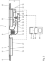
- a hob system 1 with a device 2 for extracting cooking fumes, in particular with a hob extractor, and a method for controlling such a device 2 are described.
- the hob system 1 comprises at least one such device 2 and at least one hob 3 for heating food.
- the at least one hob 3 can be designed as a radiant hob and/or as an induction hob and/or as a mass hob and/or as a gas hob.
- the at least one hob 3 preferably has at least two, in particular at least three, in particular at least four, and/or a maximum of seven, in particular a maximum of six, in particular a maximum of four, cooking zones 4.
- the hob system 1 further comprises a control device 5.
- the control device 5 is designed as a common control device 5 for controlling both the at least one hob 3 and the device 2.
- the device 2 and the at least one hob 3 can comprise separately designed control devices.
- the hob system 1 with the device 2 and the hob 3 is designed as an assembly unit.
- the hob system 1 is designed in particular for insertion into a kitchen worktop 6.
- the kitchen worktop 6 is a component of a kitchen furniture item 7.
- the kitchen worktop 6 is arranged on a kitchen base cabinet 8.
- the device 2 has an inflow opening 9 for the cooking vapors to flow into the device 2.
- An inflow grille 10 is arranged at the inflow opening 9.
- the inflow opening 9 penetrates a food support 11, in particular a hob plate, of the hob 3.
- the inflow opening overlaps a geometric center of gravity of the hob 3, in particular of the food support 11, in an orthogonal projection onto a hob plane 12.
- a user interface 13 of the control device 5 is arranged on the hob 3.
- the hob 3 in particular the food support 11, overlaps the user interface 13 in an orthogonal projection onto the hob plane 12 at least partially, in particular completely.
- the user interface 13 comprises a display means 14, in particular a screen, and/or an input means, in particular a touch-sensitive sensor, in particular a touch-sensitive screen 14.
- the at least one hob 3 has a hob housing 15.
- several energy converters 16 for converting electrical energy into heat radiation, in particular into induction radiation, are arranged.
- the food support 11, in particular the hob plate, is designed as a glass-ceramic plate.
- the at least one device 2 and the at least one hob 3 are attached to the food support 11, in particular glued to it.
- the hob system 1 is attached to the kitchen worktop 6 by means of the food support 11, in particular the food support 11 rests on the kitchen worktop 6.
- the device 2 comprises a flow channel 17 for guiding the cooking fumes and a fan 18 for conveying the cooking fumes through the flow channel 17.
- the fan 18 is a cooking fume fan, in particular a radial fan.
- the flow channel 17 comprises a negative pressure channel section 19 and a positive pressure channel section (not shown).
- the negative pressure channel section extends between the inlet opening 9 and the fan 18, in particular a suction side of the fan 18.
- the negative pressure channel section 19 penetrates the food carrier 11 and/or the kitchen worktop 6.
- the hob system 1 designed as an assembly unit comprises in particular the at least one hob 3 with the food support 11 and the at least one device 2 with the negative pressure channel section 19 and the fan 18.
- the fan 18 has a fan wheel 20 and a fan motor 21.
- the fan wheel 20 is arranged in a fan housing 22, which is preferably spiral-shaped.
- the fan housing 22 can be formed integrally with the flow channel 17 or separately from it.
- the fan 18 has a speed sensor 23 for detecting the speed of the fan 18, in particular the fan motor 21.
- the device 2 has a first filter 24.
- the first filter 24 is designed as a grease filter insert.
- the first filter 24 can be removed reversibly, in particular without tools, from the flow channel 17, in particular from the negative pressure channel section 19, in particular through the inflow opening 9.
- the device 2 can have a second filter (not shown), in particular an odor filter, in particular an activated carbon filter, which is arranged in the flow channel 17, in particular in the negative pressure channel section 19 and/or in the positive pressure channel section.
- the hob system 1, in particular with the at least one hob 3 and the at least one device 2, in particular comprising the negative pressure channel section 19 and the fan 18, has a total height H of 150 mm.
- the control device 5 has a computing unit 25 for processing electronic signals, in particular a processor for processing digital data, and a memory unit 26 for storing digital data.
- the computing unit 25 is in signal connection with the user interface 13 and the memory unit 26.
- the control device 5, in particular the computing unit 25, is in signal connection with the at least one hob 3, in particular with at least one power unit 27 of the hob 3, and/or with the at least one fan 18.
- the device 2, in particular the fan 18, comprises a power sensor 28 for detecting a power signal P that correlates with the electrical power supplied to the fan 18.
- the hob system 1, the device 2 and the control device 5 function as follows:
- the hob system 1 is initially out of operation, in particular the device 2 is out of operation.
- the computing unit 25 provides a signal for heating the food arranged on the cooking surface 4, in particular for activating the at least one power unit 27 and for emitting the heat radiation to the associated energy converter 16.
- the food is heated. Cooking fumes develop on the heated food.
- a user input for activating the device 2 for extracting cooking fumes is detected by means of the user interface 13. Based on the user input, the control device 5 provides a first control signal ⁇ 1 for operating the fan 18, in particular the fan motor 21.
- the user input for controlling the extraction power of the device 2 preferably corresponds to a power level.
- the user can preferably choose between a finite number of power levels.
- the number of selectable power levels, in particular offered to the user via the user interface 13, is preferably in a range from three to twenty, in particular from four to sixteen, in particular from eight to twelve, in particular the number of power levels is ten.
- the memory unit 26 preferably stores control data which link the respective power level with a specific control signal ⁇ for controlling the fan 18, in particular the fan motor 21.
- the control data for each of the power levels comprise a pair of values which link the respective power level with a specific control signal ⁇ .
- a the control signal ⁇ corresponding to the power level selected by the user is determined.
- the computing unit 25 provides the first control signal ⁇ 1 corresponding to the power level to the fan 18, in particular to the fan motor 21.
- the fan 18 is operated according to the first control signal ⁇ 1 .
- the control signal ⁇ in particular the first control signal ⁇ 1 , is preferably a PWM signal.
- a first operating state Qi of the fan 18 is established.
- the first operating state Qi brought about by the first control signal ⁇ 1 depends on the air conveying properties of the fan 18 and on the operating conditions under which the fan 18 is operated.
- the operating conditions are particularly dependent on the flow resistance R of the device 2, in particular of the flow channel 17 and/or of the at least one filter 24, and on the environment of the device 2, in particular on whether the room, in particular a kitchen room, in which the device 2 is arranged is largely hermetically sealed or whether a window, in particular arranged near the device 2, is open, in particular when the device 2 is operated in an exhaust air mode.
- the flow resistance R varies in particular due to a variable saturation of the at least one filter 24 and/or due to changed environmental conditions. Consequently, the first operating state Q 1 , which is established due to the first control signal ⁇ 1 , is not constant over time, but rather variable.
- a first measurement signal n 1 is recorded that correlates with the first operating state Qi of the fan 18.
- the first measurement signal n 1 corresponds to the speed n of the fan 18, in particular of the fan motor 21 and/or the fan wheel 20.
- the volume flow Q conveyed by the fan 18 is decisive for the extraction of cooking fumes.
- the greater the volume flow Q the greater the amount of air and, accordingly, cooking fumes that can be extracted by the device 2 per unit of time.
- the energy consumption of the fan 18 and the noise emission of the device 2 also increase.
- the operating state, in particular the volume flow Q is controlled, in particular regulated, to a predetermined second operating state Q 2 , in particular a target operating state Qs.
- the variable flow resistance R must be taken into account.
- Fan characteristics are stored in the memory unit 26.
- the fan characteristics indicate the resulting operating state Q, in particular the resulting volume flow Q, of the fan 18 for various combinations of the control signal ⁇ , in particular the PWM signal, and the measurement signal, in particular the speed n.
- the PWM signal ⁇ corresponds to a duty cycle in percent, in particular the percentage ratio between the pulse duration and a pulse period duration of the control signal ⁇ .
- the PWM signal ⁇ is also referred to as the PWM ratio ⁇ .
- the control signal ⁇ preferably controls the power, in particular the electrical power P, with which the fan 18 is operated.
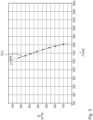
- the operating state Q of the fan 18, in particular the volume flow Q conveyed by the fan 18, is shown against the speed n of the fan motor 21.
- the fan characteristics shown were determined experimentally for the fan 18. For the experimental determination of these fan characteristics, the fan 18 was measured alone, in particular without a flow channel 17.
- the resulting speeds n and the resulting volume flow Q were determined for different flow resistances R. Different flow resistances R can be achieved for the experimental determination of the fan characteristics by throttling the fan 18, i.e. for different throttling states, for example by means of a throttle valve.
- the individual measuring points are marked with crosses. These measuring points are operating points of the fan 18.
- a function F approximately reflects the course of the volume flow Q over the speed n.
- the function F can, for example, be a polynomial function, in particular a third-order polynomial function, which on average comes closest to the experimentally determined measurement data.
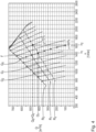
- the Fig.4 shows that the fan characteristics which arise with different measurement signals n, in particular with different speeds n, are operating states Q, in particular volume flows Q, for different control signals ⁇ , in particular PWM signals ⁇ .
- the course of the volume flow Q over the speed n is shown for different PWM ratios ⁇ , in particular from 30% to 100%, in particular in 5% steps.
- the fan characteristics can be available for any other step sizes and ranges, in particular from 0% to 100%, of PWM ratios ⁇ .
- the step sizes of the PWM ratios ⁇ preferably correlate with the number of power levels which can be set, in particular by a user.
- the speed n decreases for a constant PWM signal ⁇ with increasing flow resistance R, i.e. increasing throttling.
- the volume flow Q decreases with increasing throttling.
- an individual mathematical function F can be determined, which indicates the volume flow Q as a function of the speed n.
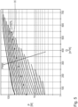
- the flow resistance R 0 is present when the fan 18 is operated with free air flow, in particular without the flow channel 17.
- the flow resistance R 1 is present when the fan 18 is arranged in the flow channel 17, the device 2 being operated in an exhaust air mode, with an open window and with a fresh filter 24.
- the flow resistance R 1 is greater than the flow resistance R 0 .
- the flow resistance R 2 is present when the fan 18 is in an exhaust air mode, with the window closed and with at least partially saturated filters 24.
- the flow resistance R 2 is greater than the flow resistance R 1 .
- the course of the volume flow Q over the speed n at constant flow resistance R is preferably determined using the experimentally determined data regarding the volume flow Q over the speed n at constant control signal ⁇ , in particular PWM ratio ⁇ .
- the course of the volume flow Q over the speed n can be described for the respective constant flow resistances R 0 , R 1 , R 2 .
- control device 5 is preconfigured for operating the device 2, in particular the fan 18.
- Fixed control signals ⁇ are stored for the power levels 1 of 10 and 10 of 10.
- the power levels that can be selected by the user for operating the fan 18 are each linked to a control signal ⁇ based on control data stored in the memory unit 26.
- the control data includes, for example, the value for the PWM signal ⁇ of 60%.
- the volume flow Q resulting from this power level or from this PWM signal ⁇ depends on the current operating conditions of the fan 18, which vary over time, in particular on the flow resistance R, in particular on the geometry of the flow channel 17 and the flow properties of the filters 24, which vary over time.
- the device 2 in particular the fan 18, is controlled by a power level selected by the user, in particular with the associated PWM signal ⁇ , in particular the first control signal ⁇ 1 .
- a first measurement signal n 1 is recorded in the form of the first speed n.
- the measurement signal n correlates with the operating state Q, in particular with the flow resistance R.
- the fan characteristics are stored in the memory unit 26 using the functions F for the different PWM signals ⁇ .
- the resulting first volume flow Qi is determined based on the first speed n 1 .
- a target operating state Q S in particular a target volume flow Q 2 , Qs , is also stored in the memory unit 26 for the respective power level.
- the operating state Q of the fan 18 is set, in particular regulated, to the target operating state Q 2 , Qs using the fan characteristics.
- the target operating state Q 2 , Qs is compared with the current operating state Qi. Based on the comparison result, a second control signal ⁇ 2 is generated to operate the fan 18 in the target operating state Q 2 , Qs .
- a difference between the target volume flow Q 2 , Qs and the current actual volume flow Qi is determined.
- the difference is used to determine the required control signal ⁇ 2 , in particular the required PWM signal ⁇ 2 , which is required to achieve the target volume flow Q 2 , Q S.
- the control signal ⁇ in particular the second control signal ⁇ 2 , can be determined using the function G 2 .
- the function G can in particular be an interpolation between two functions F.
- the function G can be completely or incompletely continuous, in particular only continuous between two neighboring functions F.
- the function G can be defined as an interpolation between two neighboring functions F and/or as an interpolation between all functions F.
- control signal ⁇ 2 required to achieve the second operating state Q 2 in particular the target operating state Q S , can be determined using a control system which is based on the volume flow Q as the controlled variable, wherein the volume flow Q is determined using the fan characteristics on the basis of the first speed n 1 and the first control signal ⁇ 1 .
- control signal ⁇ 2 required to achieve the desired operating state Q 2 , Qs can be determined by interpolation of the experimentally determined characteristics.
- the fan 18 is operated with the second control signal ⁇ 2 in the second operating state Q 2 , in particular for conveying the second volume flow Q 2 .
- the control data stored in the storage unit 26 are overwritten based on the newly acquired knowledge about the PWM ratio ⁇ 2 required for the target operating state Q 2 , Qs.
- the resulting volume flow Q then corresponds to the Target volume flow Q S , which is stored in the control data, in particular on the storage unit 26, for this power level.
- control data can only be done for the selected performance level.
- a new control signal ⁇ can be stored for each of the power levels that can be selected by the user, which corresponds to the target volume flow Qs associated with the respective power level.
- the control signal can be determined for the respective target volume flow Qs using the function G and/or by interpolating the experimentally determined fan characteristics.
- the control signals ⁇ required for various target operating states Qs can be determined using a single measurement signal n for a given control signal ⁇ .
- a change in the control signal ⁇ is limited by at least one limit value.
- the limit value can be a limit value for the resulting speed n or a limit value for the control signal ⁇ . This advantageously ensures that the device 2, in particular the fan 18, can be operated in a range which is particularly energy efficient and/or in which the noise emission of the device 2 is particularly low.
- the device 2 By comparing the control signal ⁇ and/or the measurement signal n with the respective limit value, it can be determined whether the device 2, in particular the fan 18, is operated within a permissible range. For example, the presence of a fault condition can be detected, when the control signal ⁇ and/or the measurement signal n reach the limit value specified in this regard. A warning signal can be issued to the user when such a fault condition exists.
- a fault condition can exist, for example, when the at least one filter 24 has reached a certain saturation and/or when an object, for example a dish towel, has entered the device 2 and blocked the flow channel 17.
- Such a method promotes the maintenance of the device 2.
- the device 2 is therefore particularly reliable in operation.
- the measurement signal can be detected in the form of the electrical power P consumed by the fan motor 21.
- the volume flow Q can equally be determined based on the detected electrical power P or based on both measurement signals n, P.
- the device 2, in particular the fan 18, can be adjusted particularly precisely to a predetermined operating state Q 2 , Q S can be set.
- the predetermined operating state Q 2 , Q S can be precisely set independently of the operating conditions, in particular the installation situation, of the device 2, in particular of the fan 18, in particular independently of a temporal change in the flow resistance R of the device 2 or its surroundings. Because the operating state Q can be precisely set, inadequate extraction of the cooking fumes can be reliably prevented. Likewise, an excessive volume flow Q can be prevented from leading to unnecessarily high energy consumption or unnecessarily loud noise.
- the method described above ensures that the device 2 for extracting cooking fumes is controlled in a particularly energy-efficient manner, whereby noise emissions are reduced and the extraction volume flow Q required for extracting the cooking fumes is provided particularly reliably.
Landscapes
- Engineering & Computer Science (AREA)
- Mechanical Engineering (AREA)
- General Engineering & Computer Science (AREA)
- Chemical & Material Sciences (AREA)
- Combustion & Propulsion (AREA)
- Ventilation (AREA)
Applications Claiming Priority (1)
| Application Number | Priority Date | Filing Date | Title |
|---|---|---|---|
| DE102022210727.6A DE102022210727A1 (de) | 2022-10-11 | 2022-10-11 | Verfahren zum Steuern einer Vorrichtung zum Abzug von Kochdünsten, insbesondere zum Steuern eines Kochfeldabzugs, Steuereinrichtung, Vorrichtung und Kochfeldsystem |
Publications (1)
| Publication Number | Publication Date |
|---|---|
| EP4354024A1 true EP4354024A1 (fr) | 2024-04-17 |
Family
ID=88315560
Family Applications (1)
| Application Number | Title | Priority Date | Filing Date |
|---|---|---|---|
| EP23202786.2A Pending EP4354024A1 (fr) | 2022-10-11 | 2023-10-10 | Procédé de commande d'un dispositif d'évacuation de vapeurs de cuisson, en particulier pour commander une hotte de cuisson, dispositif de commande, dispositif de cuisson et système de table de cuisson |
Country Status (2)
| Country | Link |
|---|---|
| EP (1) | EP4354024A1 (fr) |
| DE (1) | DE102022210727A1 (fr) |
Families Citing this family (1)
| Publication number | Priority date | Publication date | Assignee | Title |
|---|---|---|---|---|
| DE102022210727A1 (de) | 2022-10-11 | 2024-04-11 | BORA - Vertriebs GmbH & Co KG | Verfahren zum Steuern einer Vorrichtung zum Abzug von Kochdünsten, insbesondere zum Steuern eines Kochfeldabzugs, Steuereinrichtung, Vorrichtung und Kochfeldsystem |
Citations (6)
| Publication number | Priority date | Publication date | Assignee | Title |
|---|---|---|---|---|
| DE102005045137A1 (de) * | 2005-09-22 | 2007-04-05 | Minebea Co., Ltd., Kitasaku | Lüftereinheit mit einer vorgegebenen künstlichen Kennlinie und Verfahren zu dessen Betrieb |
| GB2432015A (en) | 2005-10-19 | 2007-05-09 | Ebm Papst Uk Ltd | A method for comissioning a fan |
| GB2457534A (en) * | 2008-01-16 | 2009-08-26 | Ebm Papst Uk Ltd | Electric-motor driven fan speed control |
| WO2013156922A2 (fr) * | 2012-04-17 | 2013-10-24 | Indesit Company S.P.A. | Hotte et procédé pour son exploitation |
| DE202017104349U1 (de) * | 2017-07-20 | 2017-10-16 | Ebm-Papst Mulfingen Gmbh & Co. Kg | Vorrichtung zum Regeln von wenigstens zwei Ventilatoren |
| DE102022210727A1 (de) | 2022-10-11 | 2024-04-11 | BORA - Vertriebs GmbH & Co KG | Verfahren zum Steuern einer Vorrichtung zum Abzug von Kochdünsten, insbesondere zum Steuern eines Kochfeldabzugs, Steuereinrichtung, Vorrichtung und Kochfeldsystem |
Family Cites Families (1)
| Publication number | Priority date | Publication date | Assignee | Title |
|---|---|---|---|---|
| CN112752926B (zh) | 2018-07-24 | 2024-03-29 | 威廉·布鲁克鲍尔 | 炉灶系统和用于向下排出烹饪烟气的烟气排出装置 |
-
2022
- 2022-10-11 DE DE102022210727.6A patent/DE102022210727A1/de active Pending
-
2023
- 2023-10-10 EP EP23202786.2A patent/EP4354024A1/fr active Pending
Patent Citations (6)
| Publication number | Priority date | Publication date | Assignee | Title |
|---|---|---|---|---|
| DE102005045137A1 (de) * | 2005-09-22 | 2007-04-05 | Minebea Co., Ltd., Kitasaku | Lüftereinheit mit einer vorgegebenen künstlichen Kennlinie und Verfahren zu dessen Betrieb |
| GB2432015A (en) | 2005-10-19 | 2007-05-09 | Ebm Papst Uk Ltd | A method for comissioning a fan |
| GB2457534A (en) * | 2008-01-16 | 2009-08-26 | Ebm Papst Uk Ltd | Electric-motor driven fan speed control |
| WO2013156922A2 (fr) * | 2012-04-17 | 2013-10-24 | Indesit Company S.P.A. | Hotte et procédé pour son exploitation |
| DE202017104349U1 (de) * | 2017-07-20 | 2017-10-16 | Ebm-Papst Mulfingen Gmbh & Co. Kg | Vorrichtung zum Regeln von wenigstens zwei Ventilatoren |
| DE102022210727A1 (de) | 2022-10-11 | 2024-04-11 | BORA - Vertriebs GmbH & Co KG | Verfahren zum Steuern einer Vorrichtung zum Abzug von Kochdünsten, insbesondere zum Steuern eines Kochfeldabzugs, Steuereinrichtung, Vorrichtung und Kochfeldsystem |
Also Published As
| Publication number | Publication date |
|---|---|
| DE102022210727A1 (de) | 2024-04-11 |
Similar Documents
| Publication | Publication Date | Title |
|---|---|---|
| EP4354024A1 (fr) | Procédé de commande d'un dispositif d'évacuation de vapeurs de cuisson, en particulier pour commander une hotte de cuisson, dispositif de commande, dispositif de cuisson et système de table de cuisson | |
| EP1712844B1 (fr) | Procédé et dispositif de commande de la température d'un four de cuisson | |
| EP2880368B1 (fr) | Hotte aspirante et procédé d'activation d'un moteur de ventilateur | |
| EP1732357A2 (fr) | Dispositif de chauffage pour appareils de cuisson à induction | |
| DE102013110489B4 (de) | Gargerät sowie Verfahren zur Erkennung des Verschmutzungsgrades einer Filtereinheit | |
| EP1278993A1 (fr) | Hotte aspirante | |
| WO2001014798A1 (fr) | Systeme de commande ou de reglage d'une cuisiniere | |
| DE102019210976B4 (de) | Kochfeldsystem | |
| DE102019202088A1 (de) | Kochfeldsystem | |
| CH705766A2 (de) | Backofen mit klimagesteuerter Temperaturbegrenzung. | |
| EP1452804A1 (fr) | Dispositif d aspiration de gaz d un appareil de chauffage électrique et procédé pour son fonctionnement | |
| EP2971978B1 (fr) | Procédé pour déterminer un état de fonctionnement d'un système de hotte aspirante | |
| DE102013015122A1 (de) | Verfahren zum Überwachen eines Luftstroms in einem Luftströmungskanal | |
| EP3255348A1 (fr) | Plaque de cuisson équipée d'une hotte aspirante et adaptation des étapes de puissance en fonction de l'état de fonctionnement de la hotte aspirante d'un distributeur d'énergie et procédé de fonctionnement d'une telle plaque de cuisson | |
| EP3082378B1 (fr) | Plaque de cuisson | |
| DE102015109053B4 (de) | Kochfeldeinrichtung und Verfahren zum Betreiben | |
| EP4075067A1 (fr) | Procédé et système de détermination d'un moment de remplacement d'un filtre à odeurs et hotte aspirante | |
| EP3772620A1 (fr) | Système de traitement de l'air permettant d'améliorer une qualité de l'air d'un air intérieur dans une pièce et son procédé de fonctionnement | |
| EP3573737A1 (fr) | Dispositif et procédé de détection d'un colmatage de filtre | |
| DE102007011634A1 (de) | Abluftsystem für Großküchen und Schnellrestaurants | |
| DE102008039316B4 (de) | Verfahren zum Reduzieren einer Rauchentstehung beim Garen und Gargerät hierfür | |
| DE102015115325A1 (de) | Dunstabzugsvorrichtung und Dunstabzugssystem sowie Verfahren zum Betreiben | |
| DE102020115654A1 (de) | Dunstabzugshaube und an einem Gaskochfeld angeordneter oder anordenbarer Durchflussmesser, sowie Verfahren zum Betreiben der Dunstabzugshaube und des Durchflussmessers | |
| EP3427632B1 (fr) | Procédé de fonctionnement pour un lave-vaisselle doté d'un circuit de pompe à chaleur et lave-vaisselle doté d'un circuit de pompe à chaleur | |
| BE1029515B1 (de) | Kochsystem und Verfahren zum Betreiben |
Legal Events
| Date | Code | Title | Description |
|---|---|---|---|
| PUAI | Public reference made under article 153(3) epc to a published international application that has entered the european phase |
Free format text: ORIGINAL CODE: 0009012 |
|
| STAA | Information on the status of an ep patent application or granted ep patent |
Free format text: STATUS: THE APPLICATION HAS BEEN PUBLISHED |
|
| AK | Designated contracting states |
Kind code of ref document: A1 Designated state(s): AL AT BE BG CH CY CZ DE DK EE ES FI FR GB GR HR HU IE IS IT LI LT LU LV MC ME MK MT NL NO PL PT RO RS SE SI SK SM TR |