EP4353644A1 - Handrail and elevator - Google Patents
Handrail and elevator Download PDFInfo
- Publication number
- EP4353644A1 EP4353644A1 EP21945037.6A EP21945037A EP4353644A1 EP 4353644 A1 EP4353644 A1 EP 4353644A1 EP 21945037 A EP21945037 A EP 21945037A EP 4353644 A1 EP4353644 A1 EP 4353644A1
- Authority
- EP
- European Patent Office
- Prior art keywords
- sliding
- section
- posts
- switch
- handrail
- Prior art date
- Legal status (The legal status is an assumption and is not a legal conclusion. Google has not performed a legal analysis and makes no representation as to the accuracy of the status listed.)
- Pending
Links
Images





Classifications
-
- B—PERFORMING OPERATIONS; TRANSPORTING
- B66—HOISTING; LIFTING; HAULING
- B66B—ELEVATORS; ESCALATORS OR MOVING WALKWAYS
- B66B5/00—Applications of checking, fault-correcting, or safety devices in elevators
- B66B5/0043—Devices enhancing safety during maintenance
- B66B5/005—Safety of maintenance personnel
- B66B5/0081—Safety of maintenance personnel by preventing falling by means of safety fences or handrails, being operable or not, mounted on top of the elevator car
Definitions
- the present invention relates to a handrail and an elevator including the handrail.
- Patent Literature 1 discloses a car handrail that is foldably disposed on an upper section of a car of an elevator.
- the car handrail includes one side section and the other side section arranged along the car side section.
- One side section is fixed to one arm section arranged along one car side section, and the other side section is fixed to the other arm section arranged along the other car side section.
- one side section is connected to the other arm section.
- a force generated when a door is opened and closed is received by both the one arm section and the other arm section.
- Patent Literature 1 JP 2016-147727 A
- an object of the present invention is to provide a handrail capable of easily performing assembly work at an upper section of an elevator car, and an elevator including the handrail.
- a handrail of the present invention includes a plurality of support posts, a plurality of sliding posts, a rail section, a first switch section, and a second switch section.
- the plurality of support posts is fixed to an upper section of an elevator car.
- the plurality of sliding posts are slidably engaged with each of the plurality of support posts, and can protrude further upward than the upper sections of the plurality of supports.
- the rail section is fixed to the plurality of sliding posts.
- an elevator of the present invention includes an elevator car moving up and down in a hoist-way, and a handrail provided on an upper section of the elevator car.
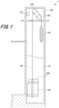
- Fig. 1 is a schematic configuration diagram illustrating a configuration example of an elevator of the present example.
- the elevator 1 of the present example moves up and down in a hoist-way 110 formed in a building structure.
- the elevator 1 includes an elevator car 120 on which people and luggage are loaded, a rope 130, a counterweight 140, and a hoisting machine 100.
- the hoist-way 110 is formed in a building structure, and a machine room 160 is provided at a top section of the hoist-way.
- the hoisting machine 100 is disposed in the machine room 160 and raises and lowers the elevator car 120 by winding the rope 130.
- a deflector wheel 150 is provided in the vicinity of the hoisting machine 100.
- the rope 130 is mounted on the deflector wheel 150.
- the counterweight 140 is set to have substantially the same mass as the mass of the elevator car 120 at the time of no load. Therefore, when no object or person is loaded in the elevator car 120, a tension ratio between the rope 130 on the elevator car 120 side and the rope 130 on the counterweight 140 side is 1. As a result, it is possible to suppress the output of the hoisting machine 100 at the time of no load.
- the elevator car 120 is connected to the counterweight 140 via the rope 130 and moves up and down in the hoist-way 110.
- a handrail 200 is provided on an upper section of the elevator car 120.
- a control board 170 illustrating a specific example of a control section according to the present invention is disposed. The control board 170 controls driving of the hoisting machine 100 and controls the lifting/lowering operation of the elevator car 120.
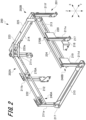
- Fig. 2 is a perspective view illustrating a reduced state of the handrail 200.
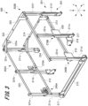
- Fig. 3 is a perspective view illustrating an expanded state of the handrail.
- the handrail 200 installed on the upper section of the elevator car 120 can be in the reduced state illustrated in Fig. 2 and the expanded state illustrated in Fig. 3 .
- the handrail 200 is brought into the reduced state.
- the handrail 200 can be prevented from interfering with the machine room 160 of the hoist-way 110.
- the handrail 200 is brought into an expanded state.
- a worker can hold the handrail 200 when working in the upper section of the elevator car 120.
- an X-axis direction indicates an entrance/exit direction of the elevator
- a Y-axis direction indicates a width direction of an entrance of the elevator
- a Z-axis direction indicates a height direction of the elevator.
- the X-axis direction and the Y-axis direction correspond to horizontal biaxial directions which are two axial directions parallel to a horizontal plane
- the Z-axis direction corresponds to a vertical direction which is a direction orthogonal to the horizontal plane.
- the entrance/exit direction of the elevator corresponds to a depth direction when the hoist-way is viewed from the elevator landing, that is, the direction in which a person enters and exits
- the width direction of the entrance of the elevator corresponds to a direction in which a door of the elevator opens and closes.
- the handrail 200 includes a support unit 201 fixed to an upper section of the elevator car 120 (see Fig. 1 ), and a first movable unit 202A and a second movable unit 202B movably connected to the support unit 201.
- the support unit 201 includes six support posts 211a, 211b, 211c, 211d, 211e, and 211f, two reinforcing sections 212 and 213, and a reinforcing connection section 214 that connects the two reinforcing sections 212 and 213.
- the support unit 201 also includes a post connection section 215 that connects the support post 211a and the support post 211d.
- the support posts 211a, 211b, and 211c are arranged at appropriate intervals in the X-axis direction.
- the support posts 211d, 211e, and 211f are arranged at appropriate intervals in the X-axis direction.
- a side of the support post 211b as viewed from the support post 211a is referred to as a back side in the X-axis direction
- a side opposite to the support post 211b as viewed from the support post 211a is referred to as a front side in the X-axis direction.
- the support post 211a faces the support post 211d
- the support post 211b faces the support post 211e
- the support post 211c faces the support post 211f.
- a side of the support post 211d as viewed from the support post 211a is defined as a right side in the Y-axis direction
- a side opposite to the support post 211d as viewed from the support post 211a is defined as a left side in the Y-axis direction.
- Each of the support posts 211a to 211f is formed in a rectangular cylindrical shape.
- One of the four side surfaces of each of the support posts 211a to 211f is opened, and a cross section thereof parallel to the horizontal plane is formed in a substantially C shape.
- the opening surfaces of the support posts 211a to 211f face the back side in the X-axis direction.
- the support posts 211a to 211f extend along the Z-axis direction.
- a fixing member 217 is provided at a lower section which is one end of each of the support posts 211a to 211f in the Z-axis direction.
- the fixing member 217 of each of the support posts 211b, 211c, 211e, and 211f is fixed to the upper section of the elevator car 120.
- a reinforcing base 218 is attached to each of the fixing members 217 of the support posts 211a and 211d.
- the reinforcing base 218 is formed of a plate body bent in a substantially L shape.
- the reinforcing base 218 includes a mounting plate section having a plane substantially perpendicular to the Y-axis direction and a reinforcement plate section having a plane substantially perpendicular to the X-axis direction.
- the fixing members 217 of the support posts 211a and 211d are fixed to the upper section of the elevator car 120 via the post connection section 215.
- the post connection section 215 is formed of a rectangular plate body elongated in the Y-axis direction and a side piece rising substantially perpendicularly from a long side of the plate body.
- the support posts 211a and 211d are integrally assembled using the post connection section 215.
- a switch unit 240A is attached to the support post 211a.
- the switch unit 240A detects the position of the first movable unit 202A in the Z-axis direction.
- the switch unit 240B is attached to the support post 211d.
- the switch unit 240B detects the position of the second movable unit 202B in the Z-axis direction. Configurations of the switch units 240A and 240B will be described later with reference to Fig. 4 .
- the support post 211b is provided with a temporary fixing mechanism 270A.
- the support post 211e is provided with a temporary fixing mechanism 270B.
- the temporary fixing mechanisms 270A and 270B respectively instruct sliding posts 221b and 221e to be described later at predetermined positions. Accordingly, the first movable unit 202A and the second movable unit 202B are held at the temporary fixing positions.
- the configurations of the temporary fixing mechanisms 270A and 270B will be described later with reference to Figs. 10 to 12 .
- the reinforcing sections 212 and 213 are formed in an elongated shape extending in the X-axis direction.
- the reinforcing section 212 is fixed to an intermediate portion of each of the support posts 211a, 211b, and 211c in the Z-axis direction.
- One end portion of the reinforcing section 212 in the X-axis direction is fixed to the support post 211a.
- the reinforcing section 213 is fixed to an intermediate portion of each of the support posts 211c, 211d, and 211f in the Z-axis direction.
- One end portion of the reinforcing section 213 in the X-axis direction is fixed to the support post 211c.
- the reinforcing connection section 214 is formed in an elongated shape extending in the Y-axis direction. Both end portions of the reinforcing connection section 214 in the Y-axis direction are respectively connected to the other end portions of the reinforcing sections 212 and 213 in the X-axis direction.
- the first movable unit 202A is movably connected to the support posts 211a, 211b, and 211c of the support unit 201. As illustrated in Fig. 3 , the first movable unit 202A includes sliding posts 221a, 221b, and 221c, a side rail section 222, and a back rail section 223.
- the sliding posts 221a, 221b, and 221c are slidably connected to the insides of the support posts 211a, 211b, and 211c. As a result, the sliding posts 221a, 221b, 221c move in the Z-axis direction along support posts 211a, 211b, 211c.
- the sliding posts 221a, 221b, and 221c are retracted into the support posts 211a, 211b, and 211c. Meanwhile, in the expanded state of the handrail 200, the sliding posts 221a, 221b, and 221c are extended out from the upper sections of the support posts 211a, 211b, and 211c.
- the sliding posts 221a, 221b, and 221c are formed in a rectangular cylindrical shape smaller than the support post 211a.
- One of the four side surfaces of each of the sliding posts 221a, 221b, and 221c is opened, and the cross section thereof parallel to the horizontal plane is formed in a substantially C shape. Opening surfaces of the sliding posts 221a, 221b, and 221c face the right side in the Y-axis direction.
- the side rail section 222 is fixed to the upper sections of the sliding posts 221a, 221b, and 221c.
- the side rail section 222 is formed in an elongated shape extending in the X-axis direction.
- the upper surface of the side rail section 222 is formed in a plane substantially perpendicular to the Z-axis direction.
- the upper surface of the side rail section 222 is set at substantially the same height as the upper ends of the sliding posts 221a, 221b, and 221c.
- the side rail section 222 faces the reinforcing section 212 of the support unit 201 in the Z-axis direction.
- the back rail section 223 is connected to a back end portion of the side rail section 222 in the X-axis direction. As a result, the back rail section 223 moves in the Z-axis direction together with the side rail section 222.
- the back rail section 223 is formed in an elongated shape extending in the Y-axis direction.
- the upper surface of the back rail section 223 is formed in a plane substantially perpendicular to the Z-axis direction.
- the upper surface of the back rail section 223 is set at substantially the same height as the upper surface of the side rail section 222.
- the back rail section 223 faces the reinforcing connection section 214 of the support unit 201 in the Z-axis direction.
- the length of the back rail section 223 in the Y-axis direction is set to about 1/2 of the length of the reinforcing connection section 214 in the Y-axis direction.
- the back rail section 223 has a stopper piece 223a. In the reduced state of the handrail 200, the stopper piece 223a abuts on the upper surface of the reinforcing connection section 214. In the expanded state of the handrail 200, the side rail section 222 and the back rail section 223 are disposed at a predetermined height at which the worker can easily hold.
- the second movable unit 202B is formed to be bilaterally symmetrical with the first movable unit 202A. That is, the second movable unit 202B includes sliding posts 221d, 221e, and 221f, a side rail section 224, and a back rail section 225. The second movable unit 202B is movably connected to the support posts 211d, 211e, and 211f of the support unit 201.
- the sliding posts 221d, 221e, and 221f are slidably connected to the insides of the support posts 211d, 211e, and 211f. As a result, the sliding posts 221d, 221e, and 221f move in the Z-axis direction along the support posts 211d, 211e, and 211f.
- the opening surfaces of the sliding posts 221d, 221e, and 221f face the left side in the Y-axis direction.
- the sliding posts 221d, 221e, and 221f are retracted into the support posts 211d, 211e, and 211f. Meanwhile, in the expanded state of the handrail 200, the sliding posts 221d, 221e, and 221f are extended out from the upper sections of the support posts 211d, 211e, and 211f.
- the side rail section 224 faces the reinforcing section 213 of the support unit 201 in the Z-axis direction.
- the back rail section 225 moves in the Z-axis direction together with the side rail section 224.
- the back rail section 225 faces the reinforcing connection section 214 of the support unit 201 in the Z-axis direction.
- the length of the back rail section 225 in the Y-axis direction is set to about 1/2 of the length of the reinforcing connection section 214 in the Y-axis direction.
- the stopper piece (not illustrated) of the back rail section 225 abuts on the upper surface of the reinforcing connection section 214.
- the back rail section 225 faces the back rail section 223. That is, the end surface on the left side in the Y-axis direction of the back rail section 225 faces the end surface on the right side in the Y-axis direction of the back rail section 223.
- the side rail section 224 and the back rail section 225 are disposed at the same height as the side rail section 222 and the back rail section 223 of the first movable unit 202A.
- the upper ends of the sliding posts 221a to 221f in the first movable unit 202A and the second movable unit 202B are substantially at the same height as the upper ends of the support posts 211a to 211f in the support unit 201.
- the first movable unit 202A and the second movable unit 202B are fixed to the support unit 201 using a fixing mechanism 300 to be described later.
- the first movable unit 202A and the second movable unit 202B are moved in the Z-axis direction (upward), and the side rail sections 222 and 224 and the back rail sections 223 and 225 are disposed at a predetermined height.
- the first movable unit 202A and the second movable unit 202B are fixed to the support unit 201 by using the fixing mechanism 300 to be described later.
- the handrail 200 is in the expanded state illustrated in Fig. 3 .
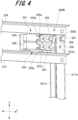
- Fig. 4 is a perspective view illustrating the switch unit 240B of the handrail 200.
- the switch units 240A and 240B have the same configuration. Therefore, here, the configuration of the switch section according to the present invention will be described by taking the switch unit 240B as an example.
- the switch unit 240B includes a first switch 251 section and a second switch section 252.
- the first switch section 251 and the second switch section 252 are attached to a switch base 219 provided on the support post 211d.
- the first switch 251 section is disposed above the second switch section 252.
- the first switch section 251 includes a normal switch 254 and a first actuator 255.
- the normal switch 254 and the first actuator 255 face each other in the X-axis direction.
- the side of the first actuator 255 opposite to the normal switch 254 faces the sliding post 221d.
- An actuator (not illustrated) of the switch unit 240A faces the sliding post 221a.
- the sliding posts 221a and 221d correspond to the sliding posts for switching according to the present invention.
- the second switch section 252 includes a maintenance switch 256 and a second actuator 257.
- the maintenance switch 256 and the second actuator 257 face each other in the X-axis direction.
- the side of the second actuator 257 opposite to the maintenance switch 256 faces the sliding post 221d.
- the normal switch 254 and the maintenance switch 256 face each other in the Z-axis direction.
- the first actuators 255 and 257 face each other in the Z-axis direction.
- the normal switch 254 and the maintenance switch 256 are fixed to the switch base 219.
- the normal switch 254 and the maintenance switch 256 are so-called momentary switches.
- the normal switch 254 and the maintenance switch 256 are turned off when buttons 254a and 256a are pressed, and are turned on when buttons 254a and 256a are not pressed.
- the first actuator 255 is formed of a rectangular plate body elongated in the X-axis direction.
- An end surface 255a of the first actuator 255 on the side of the normal switch 254 faces the button 254a of the normal switch 254 in the X-axis direction.
- An inclined surface 255b facing downward is formed on the opposite side of the first actuator 255 from the normal switch 254.
- the inclined surface 255b faces the sliding post 221d via the opening surface of the support post 211d.
- the switch base 219 supports the first actuator 255 so as to be movable in the X-axis direction.
- the first actuator 255 is movable to a first position at which the first actuator does not interfere with the sliding post 221d and a second position on the front side (sliding post 221d) in the X-axis direction with respect to the first position.
- the normal switch 254 is turned off. Meanwhile, when the first actuator 255 is disposed at the second position, the end surface 255a of the first actuator 255 does not press the button 254a of the normal switch 254. As a result, the normal switch 254 is turned on.
- the second actuator 257 is formed of a rectangular plate body elongated in the X-axis direction.
- the end surface 257a of the second actuator 257 on the maintenance switch 256 side faces the button 256a of the maintenance switch 256 in the X-axis direction.
- An inclined surface 257b facing upward is formed on the side of the second actuator 257 opposite to the maintenance switch 256.
- the inclined surface 257b faces the sliding post 221d via the opening surface of the support post 211d.
- the switch base 219 supports the second actuator 257 so as to be movable in the X-axis direction.
- the second actuator 257 is movable to a first position at which the second actuator does not interfere with the sliding post 221d and a second position on the front side (sliding post 221d) in the X-axis direction with respect to the first position.
- the maintenance switch 256 When the second actuator 257 is disposed at the first position, the end surface 257a of the second actuator 257 presses the button 256a of the maintenance switch 256. As a result, the maintenance switch 256 is turned off. Meanwhile, when the second actuator 257 is disposed at the second position, the end surface 257a of the second actuator 257 does not press the button 256a of the maintenance switch 256. As a result, the maintenance switch 256 is turned on.
- the sliding post 221d has a notch 228.
- the notch 228 is provided on a side piece of the sliding post 221d exposed from the opening surface of the support post 211d.
- the notch is formed in a quadrangular shape larger than the side section where the inclined surface 255b of the first actuator 255 is formed.
- the notch 228 faces the inclined surface 255b of the first actuator 255.
- the first actuator 255 does not interfere with the sliding post 221d and can be disposed at the second position.
- the notch 228 does not face the inclined surface 255b of the first actuator 255, the first actuator 255 interferes with the sliding post 221d. As a result, the first actuator 255 cannot be disposed at the second position.
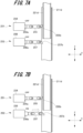
- Fig. 5 is an explanatory view illustrating ON/OFF of the switch section in the reduced state of the handrail 200.
- the handrail 200 When the elevator 1 is normally operated, the handrail 200 is brought into the reduced state. As illustrated in Fig. 5 , in the reduced state of the handrail 200, the handrail faces the notch 228 of the sliding post 221d. Therefore, the first actuator 255 of the first switch section 251 can be disposed at the second position. Meanwhile, since the second actuator 257 of the second switch section 252 interferes with the sliding post 221d, the second actuator cannot be disposed at the second position.
- the first actuator 255 When the handrail 200 is brought into the reduced state, the first actuator 255 is disposed at the second position. Accordingly, the first actuator 255 does not press the button 254a of the normal switch 254. As a result, the normal switch 254 is turned on. Meanwhile, since the second actuator 257 cannot be disposed at the second position, the button 256a of the maintenance switch 256 is pressed. As a result, the maintenance switch 256 cannot be turned on. Therefore, the maintenance switch 256 is turned off.
- Figs. 6A and 6B are explanatory views illustrating ON/OFF of the switch unit 240B during the expansion of the handrail 200.
- the handrail 200 is shifted from the reduced state to the expanded state.
- the first movable unit 202A and the second movable unit 202B are raised.
- the sliding posts 221d to 221f move upward in the Z-axis direction along the support posts 211d to 211f.
- the lower end of the notch 288 in the sliding post 221d presses the inclined surface 255b of the first actuator 255.
- the first actuator 255 moves in a direction (toward the back side in the X-axis direction) approaching the normal switch 254.
- the notch 288 of the sliding post 221d is located above the first actuator 255, and the distal end of the first actuator 255 on the inclined surface 255b side comes into contact with the side surface of the sliding post 221d.
- the first actuator 255 is disposed at the first position and presses the button 254a of the normal switch 254.
- the normal switch 254 is turned off.
- Figs. 7A and 7B are explanatory views illustrating ON/OFF of the switch unit 240B in the expanded state of the handrail 200.
- the lower end of the sliding post 221d is positioned above the second actuator 257 of the second switch section 252.
- the second actuator 257 of the second switch section 252 does not interfere with the sliding post 221d and can be disposed at the second position.
- the first actuator 255 of the first switch section 251 cannot be disposed at the second position because the first actuator interferes with the sliding post 221d.
- the second actuator 257 When the handrail 200 is brought into the expanded state, the second actuator 257 is disposed at the second position as illustrated in Fig. 7B . As a result, the second actuator 257 does not press the button 256a of the maintenance switch 256. As a result, the maintenance switch 256 is turned on. Meanwhile, since the first actuator 255 cannot be disposed at the second position, the first actuator presses the button 254a of the normal switch 254. As a result, the normal switch 254 cannot be turned on. Therefore, the normal switch 254 is turned off.
- Figs. 8A and 8B are explanatory views illustrating ON/OFF of the switch unit 240B during contraction of the handrail 200.
- the handrail 200 When the elevator 1 is normally operated after the maintenance and inspection of the elevator 1, the handrail 200 is shifted from the expanded state to the reduced state. In order to put the handrail 200 in the reduced state, the first movable unit 202A and the second movable unit 202B (see Fig. 2 ) are lowered.
- the sliding posts 221d to 221f move downward in the Z-axis direction along the support posts 211d to 211f.
- the lower end of the sliding post 221d presses the inclined surface 257b of the second actuator 257.
- the second actuator 257 moves in a direction (toward the back side in the X-axis direction) approaching the maintenance switch 256.
- Fig. 9 is a table illustrating ON/OFF patterns of the switch unit 240B and operation conditions of the elevator 1.
- the control board 170 When the normal switch 254 and the maintenance switch 256 are ON, the control board 170 disables the operation of the elevator 1. As illustrated in Figs. 5 to 8 , a situation in which the normal switch 254 and the maintenance switch 256 are turned on together cannot normally occur. Therefore, the control board 170 detects that an abnormality has occurred in the handrail 200 or the switch units 240A and 240B. Then, the control board 170 notifies that an abnormality has occurred. Examples of occurrence of abnormality include lighting of a lamp, output of a buzzer, and display by a video, an image, or the like.
- the control board 170 When the normal switch 254 and the maintenance switch 256 are OFF, the control board 170 disables the operation of the elevator 1. As illustrated in Figs. 6B and 7A , during expansion or reduction of the handrail 200, the normal switch 254 and the maintenance switch 256 may be turned off together. The handrail 200 at this time is neither in the reduced state nor in the expanded state. Therefore, the control board 170 determines that the handrail 200 is expanding or reducing, and disables the operation of the elevator 1.
- Fig. 10 is an enlarged perspective view illustrating the temporary fixing mechanism 270B.
- Fig. 11 is an explanatory view illustrating the temporary fixing mechanism 270B in the reduced state of the handrail 200.
- Fig. 12 is an explanatory view illustrating a state in which the sliding post 221e is temporarily fixed by the temporary fixing mechanism 270B of the handrail 200.
- the temporary fixing mechanisms 270A and 270B have the same configuration. Therefore, here, the configuration of the temporary fixing mechanism according to the present invention will be described by taking the temporary fixing mechanism 270B as an example.
- the temporary fixing mechanism 270B includes a stopper 281 and a shaft section 282 that rotatably supports the stopper 281.
- the stopper 281 includes a base section 285 and a hook section 286 continuous with the base section 285.
- the shaft section 282 is fixed to a hook base 220 provided on the support post 211e.
- the base section 285 is formed of a substantially rectangular plate body.
- the hook section 286 protrudes from one long side of the base section 285.
- the hook section 286 is formed of a plate body having a substantially L-shaped planar shape.
- the hook section 286 faces the sliding post 221e via the opening surface of the support post 211e (see Fig. 11 ).
- the shaft section 282 passes through the upper side of the base section 285 above the hook section 286.
- the stopper 281 is stabilized in a posture in which two long sides of the base section 285 are substantially parallel to the Z-axis direction by its own weight.
- the hook section 286 abuts on the side surface of the sliding post 221e before the two long sides of the base section 285 become substantially parallel to the Z-axis direction.
- the stopper 281 is leaned against the side surface of the sliding post 221e in a posture in which the two long sides of the base section 285 are inclined with respect to the Z-axis direction.
- the hook section 286 of the stopper 281 abuts on the side surface of the sliding post 221e.
- the sliding post 221e moves upward in the Z-axis direction along the support post 211e while being in contact with the hook section 286.
- the sliding post 221e is moved further upward than the temporarily fixed position. As a result, the hook section 286 and the sliding post 221e are disengaged. Next, the stopper 281 is rotated to separate the hook section 286 from the sliding post 221e. As a result, the temporary fixing of the second movable unit 202B is released.
- the stopper 281 may be rotated until the hook section 286 is positioned above the shaft section 282 to bring the base section 285 into contact with the side surface of the sliding post 221e.
- the stopper 281 cannot return to a stable posture due to its own weight, and the hand can be released from the stopper 281 when the sliding post 221e is moved downward.
- a protrusion section may be provided on the side surface of the sliding post 221e, and the sliding post 221e may be brought into contact with the base section 285 when moving downward.
- the stopper 281 rotates, and the state can be returned to the state (the state illustrated in Fig. 10 ) where the hook section 286 is in contact with the side surface of the sliding post 221e below the shaft section 282.
- Fig. 13 is an enlarged perspective view illustrating the fixing mechanism 300.
- One fixing mechanism 300 is provided for each pair of the support post and the sliding post. That is, the handrail 200 includes six fixing mechanisms 300.
- the fixing mechanism 300 provided in a set of the support post 211d and the sliding post 221d will be described as an example.
- the fixing mechanism 300 includes a bolt 301, a welding nut 302 to which the bolt 301 is screwed, and a fitting section 303 to which a tip portion of the bolt 301 is fitted.
- the bolt 301 and the welding nut 302 are attached to the support post 211d.
- the fitting section 303 is attached to the sliding post 221d.
- the support post 211d includes a left plate 401 forming a left side surface in the Y-axis direction, a right plate 402 forming a right side surface in the Y-axis direction, and a front plate 403 forming a front side surface in the X-axis direction.
- the sliding post 221d includes a right plate 412 forming a right side surface in the Y-axis direction, a front plate 413 forming a front side surface in the X-axis direction, and a back plate 414 forming a back side surface in the X-axis direction.
- the welding nut 302 is welded to the left plate 401 of the support post 211d.
- the bolt 301 is screwed into the welding nut 302 and passes through the left plate 401 of the support post 211d.
- a head section of the bolt 301 is disposed outside the support post 211d.
- the tip portion of the bolt 301 on the side opposite to the head section is disposed inside the support post 211d and faces the right plate 412 of the sliding post 221d.
- the fitting section 303 is fixed to the right plate 412 of the sliding post 221d.
- the fitting section 303 is formed of a quadrangular plate body. One plane of the fitting section 303 abuts on the inner surface of the right plate 412.
- the fitting section 303 has a bolt fitting hole 303a (see Fig. 15 ) into which the tip portion of the bolt 301 is fitted.
- the diameter of the bolt fitting hole 303a is slightly larger than the diameter of the tip portion of the bolt 301.
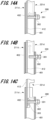
- Fig. 14A is a view illustrating a state in which the second movable unit 202B is fixed by the fixing mechanism 300 in the reduced state of the handrail 200.
- Fig. 14B is a view illustrating a state in which the fixing of the second movable unit 202B by the fixing mechanism 300 is released.
- Fig. 14C is a view illustrating a state in which the second movable unit 202B is fixed by the fixing mechanism 300 in the expanded state of the handrail 200.
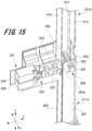
- Fig. 15 is an enlarged perspective view illustrating the fixing mechanism 300 in the temporarily fixed state of the handrail 200.
- the sliding post 221d (second movable unit 202B) can move in the Z-axis direction. Since the bolt 301 is screwed into the welding nut 302, the pressing can be loosened without being detached from the support post 211d. Then, the sliding post 221d (second movable unit 202B) is moved upward in the Z-axis direction.
- the bolt fitting hole 303a of the fitting section 303 fixed to the sliding post 221d faces the tip portion of the bolt 301.
- the tip portion of the bolt 301 is fitted into the bolt fitting hole 303a.
- the sliding post 221d (second movable unit 202B) is locked to move in the Z-axis direction.
- the sliding post 221d (second movable unit 202B) is fixed.
- the sliding post 221d (second movable unit 202B) is supported and temporarily fixed by the stopper 281 of the temporary fixing mechanism 270B.
- the position of the sliding post 221d (second movable unit 202B) fully fixed by the fixing mechanism 300 in the expanded state in the Z-axis direction is set higher than the temporarily fixed position of the sliding post 221d (second movable unit 202B) .
- Fig. 16 is an enlarged perspective view illustrating the slide guide mechanism 320 of the handrail 200.
- One slide guide mechanism 320 is provided for each pair of the support post and the sliding post. That is, the handrail 200 includes six slide guide mechanisms 320.
- the slide guide mechanism 320 provided in a set of the support post 211d and the sliding post 221d will be described as an example.
- the slide guide mechanism 320 includes a slit 331 provided in the support post 211d and an engagement pin 332 attached to the sliding post 221d.
- the slit 331 is formed in the right plate 402 of the support post 211d.
- the slit 331 extends in the Z-axis direction.
- the engagement pin 332 is fixed to the right plate 412 of the sliding post 221d.
- the engagement pin 332 movably engages with the slit 331.
- the engagement pin 332 has a shaft section passing through the slit 331 of the support post 211d and a head section disposed outside the support post 211d.
- the head section of the engagement pin 332 is formed in a disk shape having a diameter longer than the length of the slit 331 in the width direction.
- the engagement pin 332 engages with the lower end of the slit 331.
- the sliding post 221d is locked to move downward in the Z-axis direction.
- the engagement pin 332 engages with the upper end of the slit 331.
- the sliding post 221d is locked to move upward in the Z-axis direction.
- the slit 331 is provided in the support post 211d, and the engagement pin 332 is attached to the sliding post 221d.
- the slide guide mechanism according to the present invention may have a configuration in which a slit is provided in a sliding post and an engagement pin is attached to a support post.
- the handrail 200 includes the plurality of support posts 211a to 211f, the plurality of sliding posts 221a to 221f, the side rail section 222 and the back rail section 223 (rail section), and the first switch section 251 and the second switch section 252.
- the plurality of support posts 211a to 211f is fixed to an upper section of the elevator car 120.
- the plurality of sliding posts 221a to 221f are slidably engaged with the plurality of support posts 211a to 211f, respectively, and can protrude upward from upper sections of the plurality of support posts 211a to 211f.
- the side rail section 222 and the back rail section 223 are fixed to the plurality of sliding posts 221a to 221f.
- the first switch section 251 and the second switch section 252 cannot be turned on by interfering with a sliding post 221d (sliding post for switching) which is one of the plurality of sliding posts 221a to 221f.
- a sliding post 221d sliding post for switching
- the first switch section 251 interferes with the sliding post 221d which is one of the plurality of sliding posts 221a to 221f
- the second switch section 252 avoids interference with the sliding post 221d. Accordingly, the handrail 200 can be easily assembled in the expanded state. As a result, the assembly work of the handrail 200 can be easily performed at the upper section of the elevator car 120. Further, the expanded state of the handrail 200 can be easily detected.
- the first switch section 251 is prevented from interfering with the sliding post 221d (sliding post for switch), and the second switch section 252 interferes with the sliding post 221d.
- the reduced state of the handrail 200 can be easily detected.
- the first switch section 251 is disposed above the second switch section 252, and the sliding post 221d (sliding post for switching) has the notch 288 that avoids interference with the first switch section 251 in the reduced state. Accordingly, it is possible to easily realize a structure in which the sliding post 221d in the reduced state does not interfere with the first switch section 251.
- the first switch section 251 includes the normal switch 254 and the first actuator 255 that moves in a direction orthogonal to the up-down direction and presses the normal switch 254.
- the first actuator 255 has the inclined surface 255b in contact with the sliding post 221d (sliding post for switching) rising from the reduced state. Thus, by raising the sliding post 221d, the first actuator 255 can be moved to a position not interfering with the sliding post 221d.
- the normal switch 254 can be pressed by raising the sliding post 221d.
- the lower end of the sliding post 221d (sliding post for switching) is located above the second switch section 252.
- the sliding post 221d in the expanded state does not interfere with the second switch section 252.
- the second switch section 252 includes the maintenance switch 256 and the second actuator 257 that moves in a direction orthogonal to the up-down direction and presses the maintenance switch 256.
- the second actuator 257 has the inclined surface 257b in contact with the lower end of the sliding post 221d (sliding post for switching) descending from the expanded state. As a result, by raising the sliding post 221d, the second actuator 257 can be moved to the position not interfering with the sliding post 221d.
- the maintenance switch 256 can be pressed by lowering the sliding post 221d.
- the temporary fixing mechanism 270B that supports at least one (sliding post 221e) of the plurality of sliding posts 221a to 221f raised from the reduced state to the temporary fixing position is provided.
- the positions of the plurality of sliding posts 221a to 221f in the up-down direction in the expanded state are set higher than the positions of the plurality of sliding posts 221a to 221f in the up-down direction arranged at the temporary fixing positions. Accordingly, at the temporary fixing position, the second switch section 252 is not prevented from interfering with the sliding post 221d.
- the expanded state can be prevented from being detected. Therefore, it is possible to prevent the maintenance operation of the elevator 1 in a state where the plurality of sliding posts 221a to 221f is temporarily fixed.
- the temporary fixing mechanism 270B includes the stopper 281 rotatably connected to at least one (support post 211e) of the plurality of support posts 211a to 211f.
- the stopper 281 supports the lower end of at least one (support post 211e) of the plurality of sliding posts.
- the stopper 281 is stable in a posture supporting at least one of the plurality of sliding posts 221a to 221f (support post 211e) by its own weight.
- the plurality of sliding posts 221a to 221f are raised and moved above the stopper 281, so that the stopper 281 can be easily brought into a posture of supporting the sliding post 221e.
- the plurality of sliding posts 221a to 221f can be temporarily fixed easily.
- At least one of the plurality of support posts 211a to 211f has the slit 331 extending in the Z-axis direction (up-down direction).
- the sliding post engaged with at least one of the plurality of support posts 211a to 211f has an engagement pin 332 engaged with the slit 331.
- the elevator 1 includes the elevator car 120 that moves up and down in the hoist-way 110, the control board 170 (control section) that controls the raising and lowering operation of the elevator car 120, and the above-described handrail 200 provided on the upper section of the elevator car 120.
- the control board 170 control section
- the above-described handrail 200 provided on the upper section of the elevator car 120.
- the first switch section 251 is prevented from interfering with the sliding post 221d (sliding post for switch), and the second switch section 252 interferes with the sliding post 221d.
- the reduced state of the handrail 200 can be easily detected.
- the control board 170 (control section) permits the normal operation when the first switch section 251 is ON and the second switch section 252 is OFF.
- the maintenance operation which is an operation for performing maintenance and inspection work, is permitted.
- the normal operation of the elevator 1 can be performed.
- the maintenance operation of the elevator 1 can be performed.
- the control board 170 detects that an abnormality has occurred in the handrail 200.
- the operation failure can be detected, and the operation of the elevator 1 can be stopped. As a result, the elevator 1 can be operated safely.
- the first movable unit 202A and the second movable unit 202B are provided.
- the handrail according to the present invention may have a configuration in which the first movable unit 202A and the second movable unit 202B are integrally joined.
- the worker since the movable unit is divided into the first movable unit 202A and the second movable unit 202B, the worker can easily lift each of the movable units 202A and 202B alone when the handrail 200 is brought into the reduced state or the expanded state.
- the first movable unit 202A and the second movable unit 202B are integrally joined, and the length of the handrail 200 in the Y-axis direction is longer than the length in which both arms of the worker are expanded.
- the side rail section 222 (see Fig. 2 ) or the side rail section 224 is gripped and the entire movable unit is lifted.
- the weight may become equal to or more than the weight that can be lifted by one worker, and the workability of the assembly work is deteriorated.
- the switch section according to the present invention may include a biasing member that biases the actuators 255 and 257 toward the second position.
- the first actuator 255 is automatically disposed at the second position, and the normal switch 254 is turned on.
- the second actuator 257 is automatically disposed at the second position, and the maintenance switch 256 is turned on.
- a tension coil spring can be adopted as the biasing member that biases the actuators 255 and 257.
- the stopper 281 is stabilized in a posture supporting the sliding post 221e by its own weight.
- the temporary fixing mechanism according to the present invention may include a biasing member that biases the stopper 281 so as to be in a posture of supporting the sliding post 221e.
- a biasing member that biases the stopper 281 for example, a torsion coil spring can be adopted.
- the fixing mechanisms 300 are provided one by one in each pair of the support post and the sliding post.
- the number of fixing mechanisms according to the present invention can be appropriately set as long as the first movable unit 202A and the second movable unit 202B can be fixed in the reduced state and the expanded state of the handrail 200.
- the number of the temporary fixing mechanisms according to the present invention can also be set as appropriate.
- one slide guide mechanism 320 is provided for each pair of the support post and the sliding post.
- at least one slide guide mechanism according to the present invention may be provided in each of the first movable unit 202A and the second movable unit 202B.
Landscapes
- Maintenance And Inspection Apparatuses For Elevators (AREA)
- Cage And Drive Apparatuses For Elevators (AREA)
- Indicating And Signalling Devices For Elevators (AREA)
Abstract
Description
- The present invention relates to a handrail and an elevator including the handrail.
- When inspecting a device installed in a hoist-way of an elevator, a worker may get on an upper section of an elevator car to perform work. Therefore, a handrail for ensuring the safety of the worker is provided on the upper section of the elevator car. The handrail provided on the upper section of the elevator car is described in
Patent Literature 1, for example. -
Patent Literature 1 discloses a car handrail that is foldably disposed on an upper section of a car of an elevator. The car handrail includes one side section and the other side section arranged along the car side section. One side section is fixed to one arm section arranged along one car side section, and the other side section is fixed to the other arm section arranged along the other car side section. In a state where the car handrail is folded, one side section is connected to the other arm section. As a result, a force generated when a door is opened and closed is received by both the one arm section and the other arm section. - Patent Literature 1:
JP 2016-147727 A - However, in the car handrail described in
Patent Literature 1, it is difficult to secure a space in which a worker rides in the upper section of the elevator car when the car is assembled from the folded state. Therefore, it is necessary to perform the assembly work of the car handrail without getting on the upper section of the elevator car until the space for the worker to get on can be secured, and the assembly work is complicated. - In consideration of the above problems, an object of the present invention is to provide a handrail capable of easily performing assembly work at an upper section of an elevator car, and an elevator including the handrail.
- In order to solve the above problems and achieve the present object, a handrail of the present invention includes a plurality of support posts, a plurality of sliding posts, a rail section, a first switch section, and a second switch section. The plurality of support posts is fixed to an upper section of an elevator car. The plurality of sliding posts are slidably engaged with each of the plurality of support posts, and can protrude further upward than the upper sections of the plurality of supports. The rail section is fixed to the plurality of sliding posts. As a result of a first switch section and a second switch section interfering with a sliding post for switching which is one of the plurality of sliding posts, it becomes impossible to turn the first switch section and the second switch section on. When in an expanded state in which the plurality of sliding posts are extended out from the upper sections of the plurality of support posts, the first switch section interferes with the sliding post for switching, and interference between the second switch section and the sliding post for switching is avoided.
- In addition, an elevator of the present invention includes an elevator car moving up and down in a hoist-way, and a handrail provided on an upper section of the elevator car.
- According to the handrail having the above configuration, assembly work can be easily performed in the upper section of the elevator car.
-
-
Fig. 1 is a schematic configuration diagram illustrating an elevator according to one embodiment. -
Fig. 2 is a perspective view illustrating a reduced state of a handrail according to one embodiment. -
Fig. 3 is a perspective view illustrating an expanded state of the handrail according to one embodiment. -
Fig. 4 is a perspective view illustrating a switch section of the handrail according to one embodiment. -
Fig. 5 is an explanatory view illustrating ON/OFF of a switch unit in the reduced state of the handrail according to one embodiment. -
Fig. 6 is an explanatory view illustrating ON/OFF of the switch unit during expansion of the handrail according to one embodiment. -
Fig. 7 is an explanatory view illustrating ON/OFF of the switch unit in the expanded state of the handrail according to one embodiment. -
Fig. 8 is an explanatory view illustrating ON/OFF of the switch unit during reduction of the handrail according to one embodiment. -
Fig. 9 is a table illustrating ON/OFF patterns of the switch unit according to one embodiment and operation conditions of an elevator. -
Fig. 10 is an enlarged perspective view illustrating a temporary fixing mechanism of the handrail according to one embodiment. -
Fig. 11 is an explanatory view illustrating the temporary fixing mechanism in the reduced state of the handrail according to one embodiment. -
Fig. 12 is an explanatory view illustrating a state in which a sliding post is temporarily fixed by the temporary fixing mechanism of the handrail according to one embodiment. -
Fig. 13 is an enlarged perspective view illustrating a fixing mechanism of the handrail according to one embodiment. -
Fig. 14 is an explanatory view illustrating a fixing work by the fixing mechanism of the handrail according to one embodiment. -
Fig. 15 is an enlarged perspective view illustrating the fixing mechanism in the temporarily fixed state of the handrail according to one embodiment. -
Fig. 16 is an enlarged perspective view illustrating the slide guide mechanism of the handrail according to one embodiment. - Hereinafter, an elevator according to one embodiment will be described with reference to
Figs. 1 to 16 . In the drawings, the same members are denoted by the same reference numerals. - First, a configuration of an elevator according to one embodiment (hereinafter, referred to as "present example") of the present invention will be described with reference to
Fig. 1 . -
Fig. 1 is a schematic configuration diagram illustrating a configuration example of an elevator of the present example. - As illustrated in
Fig. 1 , theelevator 1 of the present example moves up and down in a hoist-way 110 formed in a building structure. Theelevator 1 includes anelevator car 120 on which people and luggage are loaded, arope 130, acounterweight 140, and a hoistingmachine 100. The hoist-way 110 is formed in a building structure, and amachine room 160 is provided at a top section of the hoist-way. - The hoisting
machine 100 is disposed in themachine room 160 and raises and lowers theelevator car 120 by winding therope 130. In addition, adeflector wheel 150 is provided in the vicinity of the hoistingmachine 100. Therope 130 is mounted on thedeflector wheel 150. - The
counterweight 140 is set to have substantially the same mass as the mass of theelevator car 120 at the time of no load. Therefore, when no object or person is loaded in theelevator car 120, a tension ratio between therope 130 on theelevator car 120 side and therope 130 on thecounterweight 140 side is 1. As a result, it is possible to suppress the output of the hoistingmachine 100 at the time of no load. - The
elevator car 120 is connected to thecounterweight 140 via therope 130 and moves up and down in the hoist-way 110. Ahandrail 200 is provided on an upper section of theelevator car 120. In themachine room 160, acontrol board 170 illustrating a specific example of a control section according to the present invention is disposed. Thecontrol board 170 controls driving of the hoistingmachine 100 and controls the lifting/lowering operation of theelevator car 120. - Next, a configuration of the
handrail 200 will be described with reference toFigs. 2 and3 . -
Fig. 2 is a perspective view illustrating a reduced state of thehandrail 200.Fig. 3 is a perspective view illustrating an expanded state of the handrail. - The
handrail 200 installed on the upper section of the elevator car 120 (seeFig. 1 ) can be in the reduced state illustrated inFig. 2 and the expanded state illustrated inFig. 3 . When theelevator 1 is normally operated, thehandrail 200 is brought into the reduced state. As a result, thehandrail 200 can be prevented from interfering with themachine room 160 of the hoist-way 110. Meanwhile, when theelevator 1 is maintained and inspected, thehandrail 200 is brought into an expanded state. As a result, a worker can hold thehandrail 200 when working in the upper section of theelevator car 120. - In
Figs. 2 and3 , an X-axis direction indicates an entrance/exit direction of the elevator, a Y-axis direction indicates a width direction of an entrance of the elevator, and a Z-axis direction indicates a height direction of the elevator. The X-axis direction and the Y-axis direction correspond to horizontal biaxial directions which are two axial directions parallel to a horizontal plane, and the Z-axis direction corresponds to a vertical direction which is a direction orthogonal to the horizontal plane. In addition, the entrance/exit direction of the elevator corresponds to a depth direction when the hoist-way is viewed from the elevator landing, that is, the direction in which a person enters and exits, and the width direction of the entrance of the elevator corresponds to a direction in which a door of the elevator opens and closes. - The
handrail 200 includes asupport unit 201 fixed to an upper section of the elevator car 120 (seeFig. 1 ), and a firstmovable unit 202A and a secondmovable unit 202B movably connected to thesupport unit 201. - The
support unit 201 includes sixsupport posts sections connection section 214 that connects the two reinforcingsections support unit 201 also includes apost connection section 215 that connects thesupport post 211a and thesupport post 211d. - The support posts 211a, 211b, and 211c are arranged at appropriate intervals in the X-axis direction. The support posts 211d, 211e, and 211f are arranged at appropriate intervals in the X-axis direction. Hereinafter, a side of the
support post 211b as viewed from thesupport post 211a is referred to as a back side in the X-axis direction, and a side opposite to thesupport post 211b as viewed from thesupport post 211a is referred to as a front side in the X-axis direction. - In the Y-axis direction, the
support post 211a faces thesupport post 211d, thesupport post 211b faces thesupport post 211e, and thesupport post 211c faces thesupport post 211f. Hereinafter, a side of thesupport post 211d as viewed from thesupport post 211a is defined as a right side in the Y-axis direction, and a side opposite to thesupport post 211d as viewed from thesupport post 211a is defined as a left side in the Y-axis direction. - Each of the
support posts 211a to 211f is formed in a rectangular cylindrical shape. One of the four side surfaces of each of thesupport posts 211a to 211f is opened, and a cross section thereof parallel to the horizontal plane is formed in a substantially C shape. The opening surfaces of thesupport posts 211a to 211f face the back side in the X-axis direction. - The support posts 211a to 211f extend along the Z-axis direction. A fixing
member 217 is provided at a lower section which is one end of each of thesupport posts 211a to 211f in the Z-axis direction. The fixingmember 217 of each of the support posts 211b, 211c, 211e, and 211f is fixed to the upper section of theelevator car 120. - A reinforcing
base 218 is attached to each of the fixingmembers 217 of thesupport posts base 218 is formed of a plate body bent in a substantially L shape. The reinforcingbase 218 includes a mounting plate section having a plane substantially perpendicular to the Y-axis direction and a reinforcement plate section having a plane substantially perpendicular to the X-axis direction. - The fixing
members 217 of thesupport posts elevator car 120 via thepost connection section 215. Thepost connection section 215 is formed of a rectangular plate body elongated in the Y-axis direction and a side piece rising substantially perpendicularly from a long side of the plate body. The support posts 211a and 211d are integrally assembled using thepost connection section 215. - A
switch unit 240A is attached to thesupport post 211a. Theswitch unit 240A detects the position of the firstmovable unit 202A in the Z-axis direction. Theswitch unit 240B is attached to thesupport post 211d. Theswitch unit 240B detects the position of the secondmovable unit 202B in the Z-axis direction. Configurations of theswitch units Fig. 4 . - The
support post 211b is provided with atemporary fixing mechanism 270A. Thesupport post 211e is provided with atemporary fixing mechanism 270B. Thetemporary fixing mechanisms posts movable unit 202A and the secondmovable unit 202B are held at the temporary fixing positions. The configurations of thetemporary fixing mechanisms Figs. 10 to 12 . - The reinforcing
sections section 212 is fixed to an intermediate portion of each of thesupport posts section 212 in the X-axis direction is fixed to thesupport post 211a. The reinforcingsection 213 is fixed to an intermediate portion of each of the support posts 211c, 211d, and 211f in the Z-axis direction. One end portion of the reinforcingsection 213 in the X-axis direction is fixed to thesupport post 211c. - The reinforcing
connection section 214 is formed in an elongated shape extending in the Y-axis direction. Both end portions of the reinforcingconnection section 214 in the Y-axis direction are respectively connected to the other end portions of the reinforcingsections - The first
movable unit 202A is movably connected to thesupport posts support unit 201. As illustrated inFig. 3 , the firstmovable unit 202A includes slidingposts side rail section 222, and aback rail section 223. - The sliding
posts support posts posts support posts - In the reduced state of the
handrail 200, the slidingposts support posts handrail 200, the slidingposts support posts - The sliding
posts support post 211a. One of the four side surfaces of each of the slidingposts posts - The
side rail section 222 is fixed to the upper sections of the slidingposts side rail section 222 is formed in an elongated shape extending in the X-axis direction. The upper surface of theside rail section 222 is formed in a plane substantially perpendicular to the Z-axis direction. The upper surface of theside rail section 222 is set at substantially the same height as the upper ends of the slidingposts side rail section 222 faces the reinforcingsection 212 of thesupport unit 201 in the Z-axis direction. - The
back rail section 223 is connected to a back end portion of theside rail section 222 in the X-axis direction. As a result, theback rail section 223 moves in the Z-axis direction together with theside rail section 222. Theback rail section 223 is formed in an elongated shape extending in the Y-axis direction. The upper surface of theback rail section 223 is formed in a plane substantially perpendicular to the Z-axis direction. The upper surface of theback rail section 223 is set at substantially the same height as the upper surface of theside rail section 222. - The
back rail section 223 faces the reinforcingconnection section 214 of thesupport unit 201 in the Z-axis direction. The length of theback rail section 223 in the Y-axis direction is set to about 1/2 of the length of the reinforcingconnection section 214 in the Y-axis direction. Theback rail section 223 has astopper piece 223a. In the reduced state of thehandrail 200, thestopper piece 223a abuts on the upper surface of the reinforcingconnection section 214. In the expanded state of thehandrail 200, theside rail section 222 and theback rail section 223 are disposed at a predetermined height at which the worker can easily hold. - The second
movable unit 202B is formed to be bilaterally symmetrical with the firstmovable unit 202A. That is, the secondmovable unit 202B includes slidingposts side rail section 224, and aback rail section 225. The secondmovable unit 202B is movably connected to thesupport posts support unit 201. - The sliding
posts support posts posts support posts posts - In the reduced state of the
handrail 200, the slidingposts support posts handrail 200, the slidingposts support posts - The
side rail section 224 faces the reinforcingsection 213 of thesupport unit 201 in the Z-axis direction. Theback rail section 225 moves in the Z-axis direction together with theside rail section 224. Theback rail section 225 faces the reinforcingconnection section 214 of thesupport unit 201 in the Z-axis direction. The length of theback rail section 225 in the Y-axis direction is set to about 1/2 of the length of the reinforcingconnection section 214 in the Y-axis direction. - In the reduced state of the
handrail 200, the stopper piece (not illustrated) of theback rail section 225 abuts on the upper surface of the reinforcingconnection section 214. In the reduced state and the expanded state of thehandrail 200, theback rail section 225 faces theback rail section 223. That is, the end surface on the left side in the Y-axis direction of theback rail section 225 faces the end surface on the right side in the Y-axis direction of theback rail section 223. - In the reduced state and the expanded state of the
handrail 200, theside rail section 224 and theback rail section 225 are disposed at the same height as theside rail section 222 and theback rail section 223 of the firstmovable unit 202A. - As illustrated in
Fig. 2 , in the reduced state of thehandrail 200, the upper ends of the slidingposts 221a to 221f in the firstmovable unit 202A and the secondmovable unit 202B are substantially at the same height as the upper ends of thesupport posts 211a to 211f in thesupport unit 201. In the reduced state of thehandrail 200, the firstmovable unit 202A and the secondmovable unit 202B are fixed to thesupport unit 201 using afixing mechanism 300 to be described later. - To switch the
handrail 200 from the reduced state to the expanded state, the firstmovable unit 202A and the secondmovable unit 202B are moved in the Z-axis direction (upward), and theside rail sections back rail sections movable unit 202A and the secondmovable unit 202B are fixed to thesupport unit 201 by using thefixing mechanism 300 to be described later. As a result, thehandrail 200 is in the expanded state illustrated inFig. 3 . - Next, configurations of the
switch units Fig. 4 . -
Fig. 4 is a perspective view illustrating theswitch unit 240B of thehandrail 200. - The
switch units switch unit 240B as an example. - As illustrated in
Fig. 4 , theswitch unit 240B includes afirst switch 251 section and asecond switch section 252. Thefirst switch section 251 and thesecond switch section 252 are attached to aswitch base 219 provided on thesupport post 211d. Thefirst switch 251 section is disposed above thesecond switch section 252. - The
first switch section 251 includes anormal switch 254 and afirst actuator 255. Thenormal switch 254 and thefirst actuator 255 face each other in the X-axis direction. The side of thefirst actuator 255 opposite to thenormal switch 254 faces the slidingpost 221d. An actuator (not illustrated) of theswitch unit 240A faces the slidingpost 221a. The slidingposts - The
second switch section 252 includes amaintenance switch 256 and asecond actuator 257. Themaintenance switch 256 and thesecond actuator 257 face each other in the X-axis direction. The side of thesecond actuator 257 opposite to themaintenance switch 256 faces the slidingpost 221d. Thenormal switch 254 and themaintenance switch 256 face each other in the Z-axis direction. Thefirst actuators - The
normal switch 254 and themaintenance switch 256 are fixed to theswitch base 219. Thenormal switch 254 and themaintenance switch 256 are so-called momentary switches. Thenormal switch 254 and themaintenance switch 256 are turned off whenbuttons buttons - The
first actuator 255 is formed of a rectangular plate body elongated in the X-axis direction. Anend surface 255a of thefirst actuator 255 on the side of thenormal switch 254 faces thebutton 254a of thenormal switch 254 in the X-axis direction. Aninclined surface 255b facing downward is formed on the opposite side of thefirst actuator 255 from thenormal switch 254. Theinclined surface 255b faces the slidingpost 221d via the opening surface of thesupport post 211d. - The
switch base 219 supports thefirst actuator 255 so as to be movable in the X-axis direction. Thefirst actuator 255 is movable to a first position at which the first actuator does not interfere with the slidingpost 221d and a second position on the front side (slidingpost 221d) in the X-axis direction with respect to the first position. - When the
first actuator 255 is disposed at the first position, theend surface 255a of thefirst actuator 255 presses thebutton 254a of thenormal switch 254. As a result, thenormal switch 254 is turned off. Meanwhile, when thefirst actuator 255 is disposed at the second position, theend surface 255a of thefirst actuator 255 does not press thebutton 254a of thenormal switch 254. As a result, thenormal switch 254 is turned on. - The
second actuator 257 is formed of a rectangular plate body elongated in the X-axis direction. Theend surface 257a of thesecond actuator 257 on themaintenance switch 256 side faces thebutton 256a of themaintenance switch 256 in the X-axis direction. Aninclined surface 257b facing upward is formed on the side of thesecond actuator 257 opposite to themaintenance switch 256. Theinclined surface 257b faces the slidingpost 221d via the opening surface of thesupport post 211d. - The
switch base 219 supports thesecond actuator 257 so as to be movable in the X-axis direction. Thesecond actuator 257 is movable to a first position at which the second actuator does not interfere with the slidingpost 221d and a second position on the front side (slidingpost 221d) in the X-axis direction with respect to the first position. - When the
second actuator 257 is disposed at the first position, theend surface 257a of thesecond actuator 257 presses thebutton 256a of themaintenance switch 256. As a result, themaintenance switch 256 is turned off. Meanwhile, when thesecond actuator 257 is disposed at the second position, theend surface 257a of thesecond actuator 257 does not press thebutton 256a of themaintenance switch 256. As a result, themaintenance switch 256 is turned on. - As illustrated in
Fig. 4 , the slidingpost 221d has anotch 228. Thenotch 228 is provided on a side piece of the slidingpost 221d exposed from the opening surface of thesupport post 211d. The notch is formed in a quadrangular shape larger than the side section where theinclined surface 255b of thefirst actuator 255 is formed. - In the reduced state of the
handrail 200, thenotch 228 faces theinclined surface 255b of thefirst actuator 255. As a result, thefirst actuator 255 does not interfere with the slidingpost 221d and can be disposed at the second position. Meanwhile, when thenotch 228 does not face theinclined surface 255b of thefirst actuator 255, thefirst actuator 255 interferes with the slidingpost 221d. As a result, thefirst actuator 255 cannot be disposed at the second position. - Next, the
switch unit 240B in the reduced state of thehandrail 200 will be described with reference toFig. 5 . -
Fig. 5 is an explanatory view illustrating ON/OFF of the switch section in the reduced state of thehandrail 200. - When the
elevator 1 is normally operated, thehandrail 200 is brought into the reduced state. As illustrated inFig. 5 , in the reduced state of thehandrail 200, the handrail faces thenotch 228 of the slidingpost 221d. Therefore, thefirst actuator 255 of thefirst switch section 251 can be disposed at the second position. Meanwhile, since thesecond actuator 257 of thesecond switch section 252 interferes with the slidingpost 221d, the second actuator cannot be disposed at the second position. - When the
handrail 200 is brought into the reduced state, thefirst actuator 255 is disposed at the second position. Accordingly, thefirst actuator 255 does not press thebutton 254a of thenormal switch 254. As a result, thenormal switch 254 is turned on. Meanwhile, since thesecond actuator 257 cannot be disposed at the second position, thebutton 256a of themaintenance switch 256 is pressed. As a result, themaintenance switch 256 cannot be turned on. Therefore, themaintenance switch 256 is turned off. - Next, the
switch unit 240B during expansion of thehandrail 200 will be described with reference toFigs. 6A and 6B . -
Figs. 6A and 6B are explanatory views illustrating ON/OFF of theswitch unit 240B during the expansion of thehandrail 200. - When the
elevator 1 is maintained and inspected, thehandrail 200 is shifted from the reduced state to the expanded state. In order to put thehandrail 200 in the expanded state, the firstmovable unit 202A and the secondmovable unit 202B (seeFig. 2 ) are raised. - When the second
movable unit 202B is raised, the slidingposts 221d to 221f move upward in the Z-axis direction along the support posts 211d to 211f. In this case, as illustrated inFig. 6A , the lower end of thenotch 288 in the slidingpost 221d presses theinclined surface 255b of thefirst actuator 255. As a result, thefirst actuator 255 moves in a direction (toward the back side in the X-axis direction) approaching thenormal switch 254. - When the sliding
posts 221d to 221f further move upward in the Z-axis direction, as illustrated inFig. 6B , thenotch 288 of the slidingpost 221d is located above thefirst actuator 255, and the distal end of thefirst actuator 255 on theinclined surface 255b side comes into contact with the side surface of the slidingpost 221d. As a result, thefirst actuator 255 is disposed at the first position and presses thebutton 254a of thenormal switch 254. As a result, thenormal switch 254 is turned off. - As illustrated in
Figs. 6A and 6B , while the slidingpost 221d moves upward, the distal end of thesecond actuator 257 on theinclined surface 257b side is always in contact with the side surface of the slidingpost 221d. As a result, thesecond actuator 257 does not move from the first position and maintains the state of pressing thebutton 256a of themaintenance switch 256. As a result,maintenance switch 256 does not change from OFF. - Next, the
switch unit 240B in the reduced state of thehandrail 200 will be described with reference toFigs. 7A and 7B . -
Figs. 7A and 7B are explanatory views illustrating ON/OFF of theswitch unit 240B in the expanded state of thehandrail 200. - When the
handrail 200 is brought into the expanded state, as illustrated inFig. 7A , the lower end of the slidingpost 221d is positioned above thesecond actuator 257 of thesecond switch section 252. As a result, thesecond actuator 257 of thesecond switch section 252 does not interfere with the slidingpost 221d and can be disposed at the second position. Meanwhile, thefirst actuator 255 of thefirst switch section 251 cannot be disposed at the second position because the first actuator interferes with the slidingpost 221d. - When the
handrail 200 is brought into the expanded state, thesecond actuator 257 is disposed at the second position as illustrated inFig. 7B . As a result, thesecond actuator 257 does not press thebutton 256a of themaintenance switch 256. As a result, themaintenance switch 256 is turned on. Meanwhile, since thefirst actuator 255 cannot be disposed at the second position, the first actuator presses thebutton 254a of thenormal switch 254. As a result, thenormal switch 254 cannot be turned on. Therefore, thenormal switch 254 is turned off. - Next, the
switch unit 240B during the reduction of thehandrail 200 will be described with reference toFigs. 8A and 8B . -
Figs. 8A and 8B are explanatory views illustrating ON/OFF of theswitch unit 240B during contraction of thehandrail 200. - When the
elevator 1 is normally operated after the maintenance and inspection of theelevator 1, thehandrail 200 is shifted from the expanded state to the reduced state. In order to put thehandrail 200 in the reduced state, the firstmovable unit 202A and the secondmovable unit 202B (seeFig. 2 ) are lowered. - When the second
movable unit 202B is lowered, the slidingposts 221d to 221f move downward in the Z-axis direction along the support posts 211d to 211f. In this case, as illustrated inFig. 8 A , the lower end of the slidingpost 221d presses theinclined surface 257b of thesecond actuator 257. As a result, thesecond actuator 257 moves in a direction (toward the back side in the X-axis direction) approaching themaintenance switch 256. - When the sliding
posts 221d to 221f further move downward in the Z-axis direction, as illustrated inFig. 8B , the lower end of the slidingpost 221d is positioned below thesecond actuator 257, and the distal end of thesecond actuator 257 on theinclined surface 257b side comes into contact with the side surface of the slidingpost 221d. As a result, thesecond actuator 257 is disposed at the first position and presses thebutton 256a of themaintenance switch 256. As a result, themaintenance switch 256 is turned off. - As illustrated in
Figs. 8A and 8B , while the slidingpost 221d moves downward, the distal end of thefirst actuator 255 on theinclined surface 255b side is always in contact with the side surface of the slidingpost 221d. As a result, thefirst actuator 255 does not move from the first position and maintains the state of pressing thebutton 254a of thenormal switch 254. As a result, thenormal switch 254 does not change from OFF. - Next, an ON/OFF pattern of the
switch unit 240B and an operation condition of theelevator 1 will be described with reference toFig. 9 . -
Fig. 9 is a table illustrating ON/OFF patterns of theswitch unit 240B and operation conditions of theelevator 1. - As illustrated in
Fig. 9 , when thenormal switch 254 is ON and themaintenance switch 256 is OFF, thehandrail 200 is in a reduced state (seeFig. 5 ). Therefore, the control board 170 (seeFig. 1 ) enables normal operation of theelevator 1. Meanwhile, when thenormal switch 254 is OFF and themaintenance switch 256 is ON, thehandrail 200 is in the expanded state (seeFig. 7B ). Therefore, thecontrol board 170 enables a maintenance operation of theelevator 1. - When the
normal switch 254 and themaintenance switch 256 are ON, thecontrol board 170 disables the operation of theelevator 1. As illustrated inFigs. 5 to 8 , a situation in which thenormal switch 254 and themaintenance switch 256 are turned on together cannot normally occur. Therefore, thecontrol board 170 detects that an abnormality has occurred in thehandrail 200 or theswitch units control board 170 notifies that an abnormality has occurred. Examples of occurrence of abnormality include lighting of a lamp, output of a buzzer, and display by a video, an image, or the like. - When the
normal switch 254 and themaintenance switch 256 are OFF, thecontrol board 170 disables the operation of theelevator 1. As illustrated inFigs. 6B and7A , during expansion or reduction of thehandrail 200, thenormal switch 254 and themaintenance switch 256 may be turned off together. Thehandrail 200 at this time is neither in the reduced state nor in the expanded state. Therefore, thecontrol board 170 determines that thehandrail 200 is expanding or reducing, and disables the operation of theelevator 1. - Next, configurations of the
temporary fixing mechanisms Figs. 10 to 12 . -
Fig. 10 is an enlarged perspective view illustrating thetemporary fixing mechanism 270B.Fig. 11 is an explanatory view illustrating thetemporary fixing mechanism 270B in the reduced state of thehandrail 200.Fig. 12 is an explanatory view illustrating a state in which the slidingpost 221e is temporarily fixed by thetemporary fixing mechanism 270B of thehandrail 200. - The
temporary fixing mechanisms temporary fixing mechanism 270B as an example. - As illustrated in
Fig. 10 , thetemporary fixing mechanism 270B includes astopper 281 and ashaft section 282 that rotatably supports thestopper 281. Thestopper 281 includes abase section 285 and ahook section 286 continuous with thebase section 285. Theshaft section 282 is fixed to ahook base 220 provided on thesupport post 211e. - The
base section 285 is formed of a substantially rectangular plate body. Thehook section 286 protrudes from one long side of thebase section 285. Thehook section 286 is formed of a plate body having a substantially L-shaped planar shape. Thehook section 286 faces the slidingpost 221e via the opening surface of thesupport post 211e (seeFig. 11 ). - The
shaft section 282 passes through the upper side of thebase section 285 above thehook section 286. Thestopper 281 is stabilized in a posture in which two long sides of thebase section 285 are substantially parallel to the Z-axis direction by its own weight. In the reduced state of thehandrail 200, thehook section 286 abuts on the side surface of the slidingpost 221e before the two long sides of thebase section 285 become substantially parallel to the Z-axis direction. As a result, thestopper 281 is leaned against the side surface of the slidingpost 221e in a posture in which the two long sides of thebase section 285 are inclined with respect to the Z-axis direction. - As illustrated in
Fig. 11 , in the reduced state of thehandrail 200, thehook section 286 of thestopper 281 abuts on the side surface of the slidingpost 221e. When the secondmovable unit 202B is raised in a case where thehandrail 200 is switched from the reduced state to the expanded state, the slidingpost 221e moves upward in the Z-axis direction along thesupport post 211e while being in contact with thehook section 286. - As illustrated in
Fig. 12 , when the lower end of slidingpost 221e moving upward in the Z-axis direction is located above thehook section 286, thehook section 286 rotates by its own weight to take a stable posture. Accordingly, thehook section 286 supports the lower end of the slidingpost 221e. As a result, the secondmovable unit 202B is temporarily fixed. - To release the temporary fixing of the second
movable unit 202B, the slidingpost 221e is moved further upward than the temporarily fixed position. As a result, thehook section 286 and the slidingpost 221e are disengaged. Next, thestopper 281 is rotated to separate thehook section 286 from the slidingpost 221e. As a result, the temporary fixing of the secondmovable unit 202B is released. - When the temporary fixing of the second
movable unit 202B is released, thestopper 281 may be rotated until thehook section 286 is positioned above theshaft section 282 to bring thebase section 285 into contact with the side surface of the slidingpost 221e. As a result, thestopper 281 cannot return to a stable posture due to its own weight, and the hand can be released from thestopper 281 when the slidingpost 221e is moved downward. In addition, a protrusion section may be provided on the side surface of the slidingpost 221e, and the slidingpost 221e may be brought into contact with thebase section 285 when moving downward. As a result, thestopper 281 rotates, and the state can be returned to the state (the state illustrated inFig. 10 ) where thehook section 286 is in contact with the side surface of the slidingpost 221e below theshaft section 282. - Next, a configuration of the
fixing mechanism 300 will be described with reference toFig. 13 . -
Fig. 13 is an enlarged perspective view illustrating thefixing mechanism 300. - One
fixing mechanism 300 is provided for each pair of the support post and the sliding post. That is, thehandrail 200 includes six fixingmechanisms 300. Here, thefixing mechanism 300 provided in a set of thesupport post 211d and the slidingpost 221d will be described as an example. - As illustrated in
Fig. 13 , thefixing mechanism 300 includes abolt 301, awelding nut 302 to which thebolt 301 is screwed, and afitting section 303 to which a tip portion of thebolt 301 is fitted. Thebolt 301 and thewelding nut 302 are attached to thesupport post 211d. Thefitting section 303 is attached to the slidingpost 221d. - As illustrated in
Fig. 13 , thesupport post 211d includes aleft plate 401 forming a left side surface in the Y-axis direction, aright plate 402 forming a right side surface in the Y-axis direction, and afront plate 403 forming a front side surface in the X-axis direction. The slidingpost 221d includes aright plate 412 forming a right side surface in the Y-axis direction, afront plate 413 forming a front side surface in the X-axis direction, and aback plate 414 forming a back side surface in the X-axis direction. - The
welding nut 302 is welded to theleft plate 401 of thesupport post 211d. Thebolt 301 is screwed into thewelding nut 302 and passes through theleft plate 401 of thesupport post 211d. A head section of thebolt 301 is disposed outside thesupport post 211d. The tip portion of thebolt 301 on the side opposite to the head section is disposed inside thesupport post 211d and faces theright plate 412 of the slidingpost 221d. - The
fitting section 303 is fixed to theright plate 412 of the slidingpost 221d. Thefitting section 303 is formed of a quadrangular plate body. One plane of thefitting section 303 abuts on the inner surface of theright plate 412. Thefitting section 303 has a boltfitting hole 303a (seeFig. 15 ) into which the tip portion of thebolt 301 is fitted. The diameter of the boltfitting hole 303a is slightly larger than the diameter of the tip portion of thebolt 301. - Next, the fixing work by the
fixing mechanism 300 will be described with reference toFigs. 14 and15 . -
Fig. 14A is a view illustrating a state in which the secondmovable unit 202B is fixed by thefixing mechanism 300 in the reduced state of thehandrail 200.Fig. 14B is a view illustrating a state in which the fixing of the secondmovable unit 202B by thefixing mechanism 300 is released.Fig. 14C is a view illustrating a state in which the secondmovable unit 202B is fixed by thefixing mechanism 300 in the expanded state of thehandrail 200.Fig. 15 is an enlarged perspective view illustrating thefixing mechanism 300 in the temporarily fixed state of thehandrail 200. - First, the fixing of the second
movable unit 202B in the reduced state of thehandrail 200 will be described. As illustrated inFig. 14A , in the reduced state of thehandrail 200, the tip portion of thebolt 301 in thefixing mechanism 300 is pressed against theright plate 412 of the slidingpost 221d. As a result, the slidingpost 221d (secondmovable unit 202B) is locked to move in the Z-axis direction. As a result, in the reduced state of thehandrail 200, the slidingpost 221d (secondmovable unit 202B) is fixed. - When the
handrail 200 is shifted from the reduced state to the expanded state, as illustrated inFig. 14B , the pressing of thefixing mechanism 300 against the slidingpost 221d by thebolt 301 is loosened. Accordingly, the slidingpost 221d (secondmovable unit 202B) can move in the Z-axis direction. Since thebolt 301 is screwed into thewelding nut 302, the pressing can be loosened without being detached from thesupport post 211d. Then, the slidingpost 221d (secondmovable unit 202B) is moved upward in the Z-axis direction. - When the
handrail 200 is brought into the expanded state, the boltfitting hole 303a of thefitting section 303 fixed to the slidingpost 221d faces the tip portion of thebolt 301. Next, the tip portion of thebolt 301 is fitted into the boltfitting hole 303a. As a result, the slidingpost 221d (secondmovable unit 202B) is locked to move in the Z-axis direction. As a result, in the expanded state of thehandrail 200, the slidingpost 221d (secondmovable unit 202B) is fixed. - When the
handrail 200 is brought into the expanded state, the slidingpost 221d (secondmovable unit 202B) is supported and temporarily fixed by thestopper 281 of thetemporary fixing mechanism 270B. The position of the slidingpost 221d (secondmovable unit 202B) fully fixed by thefixing mechanism 300 in the expanded state in the Z-axis direction is set higher than the temporarily fixed position of the slidingpost 221d (secondmovable unit 202B) . - As illustrated in
Fig. 15 , in a state where the slidingpost 221d (secondmovable unit 202B) is temporarily fixed, the boltfitting hole 303a of thefitting section 303 is located below the tip portion of thebolt 301. Therefore, the slidingpost 221d (secondmovable unit 202B) cannot be fully fixed by fixingmechanism 300 at the temporarily fixed position. - As illustrated in
Fig. 15 , in a state where the slidingpost 221d (secondmovable unit 202B) is temporarily fixed, the lower end of the slidingpost 221d is located below thesecond actuator 257 of thesecond switch section 252. As a result, thesecond actuator 257 interferes with theback plate 414 of the slidingpost 221d, and thus cannot be disposed at the second position. As a result, themaintenance switch 256 cannot be turned on. Therefore, the maintenance operation of theelevator 1 cannot be performed in a state where the slidingpost 221d (secondmovable unit 202B) is temporarily fixed. - As illustrated in
Fig. 13 , in a state where the slidingpost 221d (secondmovable unit 202B) is fully fixed by thefixing mechanism 300, the lower end of the slidingpost 221d is located above thesecond actuator 257 of thesecond switch section 252. As a result, thesecond actuator 257 does not interfere with theback plate 414 of the slidingpost 221d, and thus can be disposed at the second position. As a result, themaintenance switch 256 can be turned on. Therefore, when the slidingpost 221d (secondmovable unit 202B) is fully fixed and thehandrail 200 is in the expanded state, it is possible to perform maintenance operation of theelevator 1. - Next, the
slide guide mechanisms 320 of the firstmovable unit 202A and the secondmovable unit 202B will be described with reference toFig. 16 . -
Fig. 16 is an enlarged perspective view illustrating theslide guide mechanism 320 of thehandrail 200. - One
slide guide mechanism 320 is provided for each pair of the support post and the sliding post. That is, thehandrail 200 includes sixslide guide mechanisms 320. Here, theslide guide mechanism 320 provided in a set of thesupport post 211d and the slidingpost 221d will be described as an example. - As illustrated in
Fig. 16 , theslide guide mechanism 320 includes aslit 331 provided in thesupport post 211d and anengagement pin 332 attached to the slidingpost 221d. Theslit 331 is formed in theright plate 402 of thesupport post 211d. Theslit 331 extends in the Z-axis direction. - The
engagement pin 332 is fixed to theright plate 412 of the slidingpost 221d. Theengagement pin 332 movably engages with theslit 331. Theengagement pin 332 has a shaft section passing through theslit 331 of thesupport post 211d and a head section disposed outside thesupport post 211d. The head section of theengagement pin 332 is formed in a disk shape having a diameter longer than the length of theslit 331 in the width direction. - In the reduced state of the
handrail 200, theengagement pin 332 engages with the lower end of theslit 331. As a result, in the reduced state of thehandrail 200, the slidingpost 221d is locked to move downward in the Z-axis direction. In the expanded state of thehandrail 200, theengagement pin 332 engages with the upper end of theslit 331. As a result, in the expanded state of thehandrail 200, the slidingpost 221d is locked to move upward in the Z-axis direction. - By providing the
slide guide mechanism 320 described above, rattling of the slidingposts 221a to 221f can be suppressed when the firstmovable unit 202A and the secondmovable unit 202B are moved in the Z-axis direction. As a result, the firstmovable unit 202A and the secondmovable unit 202B can smoothly move in the Z-axis direction. - In the present embodiment, the
slit 331 is provided in thesupport post 211d, and theengagement pin 332 is attached to the slidingpost 221d. However, the slide guide mechanism according to the present invention may have a configuration in which a slit is provided in a sliding post and an engagement pin is attached to a support post. - As described above, the
handrail 200 according to the present embodiment includes the plurality ofsupport posts 211a to 211f, the plurality of slidingposts 221a to 221f, theside rail section 222 and the back rail section 223 (rail section), and thefirst switch section 251 and thesecond switch section 252. The plurality ofsupport posts 211a to 211f is fixed to an upper section of theelevator car 120. The plurality of slidingposts 221a to 221f are slidably engaged with the plurality ofsupport posts 211a to 211f, respectively, and can protrude upward from upper sections of the plurality ofsupport posts 211a to 211f. Theside rail section 222 and theback rail section 223 are fixed to the plurality of slidingposts 221a to 221f. Thefirst switch section 251 and thesecond switch section 252 cannot be turned on by interfering with a slidingpost 221d (sliding post for switching) which is one of the plurality of slidingposts 221a to 221f. In the expanded state in which the plurality of slidingposts 221a to 221f are extended out from the upper sections of the plurality ofsupport posts 211a to 211f, thefirst switch section 251 interferes with the slidingpost 221d which is one of the plurality of slidingposts 221a to 221f, and thesecond switch section 252 avoids interference with the slidingpost 221d. Accordingly, thehandrail 200 can be easily assembled in the expanded state. As a result, the assembly work of thehandrail 200 can be easily performed at the upper section of theelevator car 120. Further, the expanded state of thehandrail 200 can be easily detected. - In the reduced state in which the plurality of sliding
posts 221a to 221f are retracted into the plurality ofsupport posts 211a to 211f, thefirst switch section 251 is prevented from interfering with the slidingpost 221d (sliding post for switch), and thesecond switch section 252 interferes with the slidingpost 221d. As a result, the reduced state of thehandrail 200 can be easily detected. - The
first switch section 251 is disposed above thesecond switch section 252, and the slidingpost 221d (sliding post for switching) has thenotch 288 that avoids interference with thefirst switch section 251 in the reduced state. Accordingly, it is possible to easily realize a structure in which the slidingpost 221d in the reduced state does not interfere with thefirst switch section 251. - The
first switch section 251 includes thenormal switch 254 and thefirst actuator 255 that moves in a direction orthogonal to the up-down direction and presses thenormal switch 254. Thefirst actuator 255 has theinclined surface 255b in contact with the slidingpost 221d (sliding post for switching) rising from the reduced state. Thus, by raising the slidingpost 221d, thefirst actuator 255 can be moved to a position not interfering with the slidingpost 221d. Thenormal switch 254 can be pressed by raising the slidingpost 221d. - In the expanded state, the lower end of the sliding
post 221d (sliding post for switching) is located above thesecond switch section 252. As a result, it is possible to easily realize a structure in which the slidingpost 221d in the expanded state does not interfere with thesecond switch section 252. - The
second switch section 252 includes themaintenance switch 256 and thesecond actuator 257 that moves in a direction orthogonal to the up-down direction and presses themaintenance switch 256. Thesecond actuator 257 has theinclined surface 257b in contact with the lower end of the slidingpost 221d (sliding post for switching) descending from the expanded state. As a result, by raising the slidingpost 221d, thesecond actuator 257 can be moved to the position not interfering with the slidingpost 221d. Themaintenance switch 256 can be pressed by lowering the slidingpost 221d. - In addition, the
temporary fixing mechanism 270B that supports at least one (slidingpost 221e) of the plurality of slidingposts 221a to 221f raised from the reduced state to the temporary fixing position is provided. The positions of the plurality of slidingposts 221a to 221f in the up-down direction in the expanded state are set higher than the positions of the plurality of slidingposts 221a to 221f in the up-down direction arranged at the temporary fixing positions. Accordingly, at the temporary fixing position, thesecond switch section 252 is not prevented from interfering with the slidingpost 221d. As a result, when the plurality of slidingposts 221a to 221f are at the temporary fixing positions, the expanded state can be prevented from being detected. Therefore, it is possible to prevent the maintenance operation of theelevator 1 in a state where the plurality of slidingposts 221a to 221f is temporarily fixed. - The
temporary fixing mechanism 270B includes thestopper 281 rotatably connected to at least one (support post 211e) of the plurality ofsupport posts 211a to 211f. Thestopper 281 supports the lower end of at least one (support post 211e) of the plurality of sliding posts. As a result, the plurality of slidingposts 221a to 221f can be temporarily fixed with a simple structure. - In addition, the
stopper 281 is stable in a posture supporting at least one of the plurality of slidingposts 221a to 221f (support post 211e) by its own weight. As a result, the plurality of slidingposts 221a to 221f are raised and moved above thestopper 281, so that thestopper 281 can be easily brought into a posture of supporting the slidingpost 221e. As a result, the plurality of slidingposts 221a to 221f can be temporarily fixed easily. - At least one of the plurality of
support posts 211a to 211f has theslit 331 extending in the Z-axis direction (up-down direction). The sliding post engaged with at least one of the plurality ofsupport posts 211a to 211f has anengagement pin 332 engaged with theslit 331. As a result, rattling of the slidingposts 221a to 221f can be suppressed. As a result, the slidingposts 221a to 221f can be smoothly moved in the Z-axis direction. - In addition, the
elevator 1 according to the present embodiment includes theelevator car 120 that moves up and down in the hoist-way 110, the control board 170 (control section) that controls the raising and lowering operation of theelevator car 120, and the above-describedhandrail 200 provided on the upper section of theelevator car 120. As a result, when the maintenance and inspection of theelevator 1 are performed, the assembly work of thehandrail 200 can be easily performed at the upper section of theelevator car 120. - In the reduced state in which the plurality of sliding
posts 221a to 221f are retracted into the plurality ofsupport posts 211a to 211f, thefirst switch section 251 is prevented from interfering with the slidingpost 221d (sliding post for switch), and thesecond switch section 252 interferes with the slidingpost 221d. As a result, the reduced state of thehandrail 200 can be easily detected. - The control board 170 (control section) permits the normal operation when the
first switch section 251 is ON and thesecond switch section 252 is OFF. In addition, when thefirst switch section 251 is OFF and thesecond switch section 252 is ON, the maintenance operation, which is an operation for performing maintenance and inspection work, is permitted. As a result, when it is detected that thehandrail 200 is in the reduced state, the normal operation of theelevator 1 can be performed. When it is detected that thehandrail 200 is in the expanded state, the maintenance operation of theelevator 1 can be performed. - In addition, when the
first switch section 251 and thesecond switch section 252 are ON, the control board 170 (control section) detects that an abnormality has occurred in thehandrail 200. As a result, when an operation failure occurs in thefirst switch section 251 or thesecond switch section 252, the operation failure can be detected, and the operation of theelevator 1 can be stopped. As a result, theelevator 1 can be operated safely. - The present invention is not limited to the embodiments described above and illustrated in the drawings, and various modifications can be made without departing from the gist of the invention described in the claims.
- In the above-described embodiment, the first
movable unit 202A and the secondmovable unit 202B are provided. However, the handrail according to the present invention may have a configuration in which the firstmovable unit 202A and the secondmovable unit 202B are integrally joined. In the present embodiment, since the movable unit is divided into the firstmovable unit 202A and the secondmovable unit 202B, the worker can easily lift each of themovable units handrail 200 is brought into the reduced state or the expanded state. - For example, it is assumed that the first
movable unit 202A and the secondmovable unit 202B are integrally joined, and the length of thehandrail 200 in the Y-axis direction is longer than the length in which both arms of the worker are expanded. In this case, the side rail section 222 (seeFig. 2 ) or theside rail section 224 is gripped and the entire movable unit is lifted. As a result, it is difficult to lift the entire movable unit in the Z-axis direction in a well-balanced manner. In addition, when the firstmovable unit 202A and the secondmovable unit 202B are integrally joined, the weight may become equal to or more than the weight that can be lifted by one worker, and the workability of the assembly work is deteriorated. - In the embodiment described above, the
first actuator 255 and thesecond actuator 257 are manually moved to the second position (the position at which the pushbutton switch is turned on). However, the switch section according to the present invention may include a biasing member that biases theactuators handrail 200 is brought into the reduced state, thefirst actuator 255 is automatically disposed at the second position, and thenormal switch 254 is turned on. When thehandrail 200 is brought into the expanded state, thesecond actuator 257 is automatically disposed at the second position, and themaintenance switch 256 is turned on. As the biasing member that biases theactuators - Further, in the above-described embodiment, the
stopper 281 is stabilized in a posture supporting the slidingpost 221e by its own weight. However, the temporary fixing mechanism according to the present invention may include a biasing member that biases thestopper 281 so as to be in a posture of supporting the slidingpost 221e. As the biasing member that biases thestopper 281, for example, a torsion coil spring can be adopted. - In addition, in the above-described embodiment, the fixing
mechanisms 300 are provided one by one in each pair of the support post and the sliding post. However, the number of fixing mechanisms according to the present invention can be appropriately set as long as the firstmovable unit 202A and the secondmovable unit 202B can be fixed in the reduced state and the expanded state of thehandrail 200. The number of the temporary fixing mechanisms according to the present invention can also be set as appropriate. - In the above-described embodiment, one
slide guide mechanism 320 is provided for each pair of the support post and the sliding post. However, at least one slide guide mechanism according to the present invention may be provided in each of the firstmovable unit 202A and the secondmovable unit 202B. - In the present specification, words such as "parallel" and "orthogonal" are used, but these do not strictly mean only "parallel" and "orthogonal", and may be in a state of "substantially parallel" or "substantially orthogonal" including "parallel" and "orthogonal" and in a range in which the function can be exhibited.
-
- 1 elevator
- 100 hoisting machine
- 110 hoist-way
- 120 elevator car
- 130 rope
- 140 counterweight
- 150 deflector wheel
- 160 machine room
- 170 control board
- 200 handrail
- 201 support unit
- 202A first movable unit
- 202B second movable unit
- 211a to 211f support post
- 219 switch base
- 220 hook base
- 221a to 221f sliding post
- 222, 224 side rail section
- 223, 225 back rail section
- 240A, 240B switch unit
- 251 first switch section
- 252 second switch section
- 254 normal switch
- 255 first actuator
- 255a end surface
- 255b inclined surface
- 256 maintenance switch
- 257 second actuator
- 257a end surface
- 257b inclined surface
- 270A, 270B temporary fixing mechanism
- 281 stopper
- 282 shaft section
- 285 base section
- 286 hook section
- 300 fixing mechanism
- 301 bolt
- 302 welding nut
- 303 fitting section
- 303a bolt fitting hole
- 320 slide guide mechanism
- 331 slit
- 332 engagement pin
Claims (14)
- A handrail comprising:a plurality of support posts fixed to an upper section of an elevator car;a plurality of sliding posts slidably engaged with each of the plurality of support posts and protruding further upward than upper sections of the plurality of support posts;a rail section is fixed to the plurality of sliding posts; anda first switch section and a second switch section interfering with a sliding post for switching which is one of the plurality of sliding posts so that it becomes impossible to turn the first switch section and the second switch section on,wherein in an expanded state in which the plurality of sliding posts are extended out from the upper sections of the plurality of support posts, the first switch section interferes with the sliding post for switching, and interference between the second switch section and the sliding post for switching is avoided.
- The handrail according to claim 1, wherein in a reduced state in which the plurality of sliding posts are retracted into the plurality of support posts, interference between the first switch section and the sliding post for switching is avoided, and the second switch section interferes with the sliding post for switching.
- The handrail according to claim 2, wherein the first switch section is disposed above the second switch section, and
the sliding post for switching has a notch that avoids interference with the first switch section in the reduced state. - The handrail according to claim 3, wherein the first switch section includes a first switch and a first actuator configured to move in a direction orthogonal to an up-down direction and press the first switch, and
the first actuator has an inclined surface in contact with the sliding post for switching rising from the reduced state. - The handrail according to claim 3, wherein a lower end of the sliding post for switching is positioned above the second switch section in the expanded state.
- The handrail according to claim 5, wherein the second switch section includes a second switch and a second actuator configured to move in a direction orthogonal to an up-down direction and press the second switch, and
the second actuator has an inclined surface in contact with a lower end of the sliding post for switching descending from the expanded state. - The handrail according to claim 2, further comprising a temporary fixing mechanism configured to support at least one of the plurality of sliding posts raised from the reduced state to a temporary fixing position,
wherein positions in the up-down direction of the plurality of sliding posts in the expanded state are set higher than positions in the up-down direction of the plurality of sliding posts arranged at the temporary fixing position. - The handrail according to claim 7, wherein the temporary fixing mechanism includes a stopper rotatably connected to at least one of the plurality of support posts, and
the stopper supports at least one lower end of the plurality of sliding posts. - The handrail according to claim 8, wherein the stopper is stable in a posture supporting at least one of the plurality of sliding posts by its own weight.
- The handrail according to claim 1, wherein one of at least one of the plurality of support posts and a sliding post engaged with at least one of the plurality of support posts has a slit extending in an up-down direction, and
the other of at least one of the plurality of support posts and the sliding post engaged with at least one of the plurality of support posts includes an engagement pin engaged with the slit. - An elevator comprising:an elevator car moving up and down in hoist-way;a control section configured to control a lifting/lowering operation of the elevator car; anda handrail provided on an upper section of the elevator car,wherein the handrail includesa plurality of support posts fixed to the upper section of the elevator car,a plurality of sliding posts slidably engaged with each of the plurality of support posts and protruding further upward than upper sections of the plurality of support posts,a rail section fixed to the plurality of sliding posts, anda first switch section and a second switch section interfering with a sliding post for switching which is one of the plurality of sliding posts so that it becomes impossible to turn the first switch section and the second switch section on, andin an expanded state in which the plurality of sliding posts are extended out from the upper sections of the plurality of support posts, the first switch section interferes with the sliding post for switching, and interference between the second switch section and the sliding post for switching is avoided.
- The elevator according to claim 11, wherein in a reduced state in which the plurality of sliding posts are retracted into the plurality of support posts, interference between the first switch section and the sliding post for switching is avoided, and the second switch section interferes with the sliding post for switching.
- The elevator according to claim 12, wherein the control section permits a normal operation when the first switch section is ON and the second switch section is OFF, and permits a maintenance operation that is operation when maintenance and inspection work is performed in a case where the first switch section is OFF and the second switch section is ON.
- The elevator according to claim 12, wherein the control section detects that an abnormality occurs in the handrail when the first switch section and the second switch section are ON.
Applications Claiming Priority (1)
| Application Number | Priority Date | Filing Date | Title |
|---|---|---|---|
| PCT/JP2021/021716 WO2022259359A1 (en) | 2021-06-08 | 2021-06-08 | Handrail and elevator |
Publications (2)
| Publication Number | Publication Date |
|---|---|
| EP4353644A1 true EP4353644A1 (en) | 2024-04-17 |
| EP4353644A4 EP4353644A4 (en) | 2025-04-23 |
Family
ID=84425031
Family Applications (1)
| Application Number | Title | Priority Date | Filing Date |
|---|---|---|---|
| EP21945037.6A Pending EP4353644A4 (en) | 2021-06-08 | 2021-06-08 | HANDRAIL AND ELEVATOR |
Country Status (4)
| Country | Link |
|---|---|
| EP (1) | EP4353644A4 (en) |
| JP (1) | JP7520232B2 (en) |
| CN (1) | CN117425612A (en) |
| WO (1) | WO2022259359A1 (en) |
Families Citing this family (1)
| Publication number | Priority date | Publication date | Assignee | Title |
|---|---|---|---|---|
| JP7718545B1 (en) * | 2024-06-20 | 2025-08-05 | フジテック株式会社 | Elevator safety fence unit and elevator safety fence |
Family Cites Families (10)
| Publication number | Priority date | Publication date | Assignee | Title |
|---|---|---|---|---|
| US20050230194A1 (en) * | 2002-05-09 | 2005-10-20 | Ryushu Nakamura | Safety fence at upper part of cab |
| EP2035315B1 (en) * | 2006-06-30 | 2012-09-05 | Otis Elevator Company | Elevator having a shallow pit and/or a low overhead |
| JP5962473B2 (en) * | 2012-12-05 | 2016-08-03 | 三菱電機ビルテクノサービス株式会社 | Elevator equipment |
| JP5951818B1 (en) | 2015-02-10 | 2016-07-13 | 東芝エレベータ株式会社 | Car handrail and a car equipped with it |
| KR101936010B1 (en) * | 2015-02-26 | 2019-01-07 | 미쓰비시덴키 가부시키가이샤 | Elevator device |
| CN108473275B (en) * | 2015-12-18 | 2020-09-15 | 因温特奥股份公司 | Elevator car with a reversible protective rail and control device for an elevator system having such an elevator car |
| DE112016007065T5 (en) * | 2016-07-15 | 2019-03-28 | Mitsubishi Electric Corporation | winder |
| JP6570754B2 (en) * | 2016-08-18 | 2019-09-04 | 三菱電機株式会社 | Elevator car handrail device |
| CN208327051U (en) * | 2018-03-08 | 2019-01-04 | 西继迅达(许昌)电梯有限公司 | A kind of elevator car top guardrail |
| CN212639602U (en) * | 2020-05-07 | 2021-03-02 | 苏州启元电梯系统有限公司 | Automatic telescopic guardrail device for lower top layer height |
-
2021
- 2021-06-08 WO PCT/JP2021/021716 patent/WO2022259359A1/en not_active Ceased
- 2021-06-08 JP JP2023527200A patent/JP7520232B2/en active Active
- 2021-06-08 EP EP21945037.6A patent/EP4353644A4/en active Pending
- 2021-06-08 CN CN202180099058.4A patent/CN117425612A/en active Pending
Also Published As
| Publication number | Publication date |
|---|---|
| JPWO2022259359A1 (en) | 2022-12-15 |
| WO2022259359A1 (en) | 2022-12-15 |
| CN117425612A (en) | 2024-01-19 |
| EP4353644A4 (en) | 2025-04-23 |
| JP7520232B2 (en) | 2024-07-22 |
Similar Documents
| Publication | Publication Date | Title |
|---|---|---|
| CN101652307B (en) | Handrail device above the elevator car | |
| JP5328267B2 (en) | Elevator car equipment | |
| JP2007063021A (en) | Lift cage with maintenance platform and maintenance method for lift facility | |
| KR20000022574A (en) | Swiching device of control board in elevator | |
| JP2009040570A (en) | Car locking device of elevator | |
| JP5217073B2 (en) | Car and elevator equipment | |
| JP5805499B2 (en) | Elevator equipment | |
| JP2011126628A (en) | Elevator inspection stand | |
| EP4353644A1 (en) | Handrail and elevator | |
| KR20040010787A (en) | On-cage handrail for elevator | |
| JP2003321174A (en) | Working fence of elevator car | |
| JP2888394B2 (en) | Elevator work floor | |
| JP2009057198A (en) | Elevator car, assembly method of elevator car, and lifting tool | |
| EP4286314A1 (en) | Elevator car with blocking member for foldable working platform | |
| JPWO2006129346A1 (en) | Elevator equipment | |
| JP2013018649A (en) | Elevator apparatus | |
| JP3170559B2 (en) | Elevator car fixing device | |
| JP6570764B2 (en) | Elevator car handrail device | |
| JP2569652Y2 (en) | Door equipment related to construction lifting equipment | |
| JP5972161B2 (en) | Elevator equipment | |
| KR100866193B1 (en) | Handrail device on the compartment of an elevator | |
| JP5581476B2 (en) | Lifting type moving scaffold | |
| CN111655603B (en) | Elevator work platform and elevator | |
| JP5673958B2 (en) | elevator | |
| JP2020125207A (en) | Jamb handle device for elevator |
Legal Events
| Date | Code | Title | Description |
|---|---|---|---|
| STAA | Information on the status of an ep patent application or granted ep patent |
Free format text: STATUS: THE INTERNATIONAL PUBLICATION HAS BEEN MADE |
|
| PUAI | Public reference made under article 153(3) epc to a published international application that has entered the european phase |
Free format text: ORIGINAL CODE: 0009012 |
|
| STAA | Information on the status of an ep patent application or granted ep patent |
Free format text: STATUS: REQUEST FOR EXAMINATION WAS MADE |
|
| 17P | Request for examination filed |
Effective date: 20231207 |
|
| AK | Designated contracting states |
Kind code of ref document: A1 Designated state(s): AL AT BE BG CH CY CZ DE DK EE ES FI FR GB GR HR HU IE IS IT LI LT LU LV MC MK MT NL NO PL PT RO RS SE SI SK SM TR |
|
| DAV | Request for validation of the european patent (deleted) | ||
| DAX | Request for extension of the european patent (deleted) | ||
| A4 | Supplementary search report drawn up and despatched |
Effective date: 20250325 |
|
| RIC1 | Information provided on ipc code assigned before grant |
Ipc: B66B 5/00 20060101AFI20250319BHEP |
|
| GRAP | Despatch of communication of intention to grant a patent |
Free format text: ORIGINAL CODE: EPIDOSNIGR1 |
|
| STAA | Information on the status of an ep patent application or granted ep patent |
Free format text: STATUS: GRANT OF PATENT IS INTENDED |
|
| RIC1 | Information provided on ipc code assigned before grant |
Ipc: B66B 5/00 20060101AFI20260302BHEP |
|
| INTG | Intention to grant announced |
Effective date: 20260312 |