EP4353582A1 - Liquefied carbon dioxide press-fitting system and liquefied carbon dioxide press-fitting method - Google Patents
Liquefied carbon dioxide press-fitting system and liquefied carbon dioxide press-fitting method Download PDFInfo
- Publication number
- EP4353582A1 EP4353582A1 EP22820301.4A EP22820301A EP4353582A1 EP 4353582 A1 EP4353582 A1 EP 4353582A1 EP 22820301 A EP22820301 A EP 22820301A EP 4353582 A1 EP4353582 A1 EP 4353582A1
- Authority
- EP
- European Patent Office
- Prior art keywords
- carbon dioxide
- dioxide gas
- liquefied carbon
- floating body
- pressure
- Prior art date
- Legal status (The legal status is an assumption and is not a legal conclusion. Google has not performed a legal analysis and makes no representation as to the accuracy of the status listed.)
- Pending
Links
Images

Classifications
-
- B—PERFORMING OPERATIONS; TRANSPORTING
- B63—SHIPS OR OTHER WATERBORNE VESSELS; RELATED EQUIPMENT
- B63B—SHIPS OR OTHER WATERBORNE VESSELS; EQUIPMENT FOR SHIPPING
- B63B27/00—Arrangement of ship-based loading or unloading equipment for cargo or passengers
- B63B27/30—Arrangement of ship-based loading or unloading equipment for transfer at sea between ships or between ships and off-shore structures
-
- B—PERFORMING OPERATIONS; TRANSPORTING
- B63—SHIPS OR OTHER WATERBORNE VESSELS; RELATED EQUIPMENT
- B63B—SHIPS OR OTHER WATERBORNE VESSELS; EQUIPMENT FOR SHIPPING
- B63B27/00—Arrangement of ship-based loading or unloading equipment for cargo or passengers
- B63B27/24—Arrangement of ship-based loading or unloading equipment for cargo or passengers of pipe-lines
Definitions
- the present invention relates to an injection system and an injection method for liquefied carbon dioxide gas (liquefied CO 2 ) in carbon capture and storage (CCS).
- liquefied CO 2 liquefied CO 2
- CCS carbon capture and storage
- Carbon capture and storage recovers CO 2 from a CO 2 generation source (for example, combustion exhaust gas from a coal-fired power plant) by a chemical absorption method or the like, compresses and liquefies the CO 2 , and injects and stores the CO 2 in a supercritical state in an underground aquifer (reservoir) shielded by a rock or the like, which is one of global warming countermeasures.
- a CO 2 generation source for example, combustion exhaust gas from a coal-fired power plant
- a chemical absorption method or the like compresses and liquefies the CO 2 , and injects and stores the CO 2 in a supercritical state in an underground aquifer (reservoir) shielded by a rock or the like, which is one of global warming countermeasures.
- CCS liquefied carbon dioxide gas transport and injection method
- the separated and recovered CO 2 is compressed and liquefied, temporarily stored in a tank on land in the form of liquefied carbon dioxide gas, loaded on a liquefied carbon dioxide gas transport ship from the tank, and shipped to a storage point.
- the liquefied carbon dioxide gas is injected from the liquefied carbon dioxide gas transport ship into the aquifer under the seabed (see, for example, Patent Literature 1) .
- Patent Literature 1 JP2016-84630 A
- the liquefied carbon dioxide gas When the liquefied carbon dioxide gas is injected into the reservoir (aquifer), the liquefied carbon dioxide gas (for example, of -10°C/2.289 MPa to -50°C/0.684 MPa) is pressurized to a predetermined pressure (10 MPa or more), and then the temperature of the gas is raised to 0°C or more to perform injection in order to prevent freezing of surrounding water and to prevent blockage due to CO 2 hydrate formation.
- a predetermined pressure 10 MPa or more
- the present invention has been made in view of such a situation, and an object of the present invention is to provide a liquefied carbon dioxide gas injection system and a liquefied carbon dioxide gas injection method capable of injecting liquefied carbon dioxide gas into the seabed at low cost.
- a liquefied carbon dioxide gas injection system includes a floating body moored offshore, a temperature raising and pressure raising facility structured to raise a temperature and a pressure of liquefied carbon dioxide gas, the temperature raising and pressurizing facility being mounted on the floating body, a loading hose structured to send liquefied carbon dioxide gas from a liquefied carbon dioxide gas storage tank in a liquefied carbon dioxide gas transport ship to the temperature raising and pressure raising facility of the floating body, and a flexible riser pipe structured to send and inject the liquefied carbon dioxide gas whose temperature and pressure are raised by the temperature raising and pressure raising facility to a seabed, the flexible riser pipe being connected to the floating body.
- the floating does not have a storage tank for liquefied carbon dioxide gas, and the injection system is under unmanned operation through remotely control from the transport ship.
- Another aspect of the present invention is a liquefied carbon dioxide gas injection method.
- the method includes approaching a floating body moored offshore by a liquefied carbon dioxide gas transport ship, connecting a gangway provided in the liquefied carbon dioxide gas transport ship to the floating body and transferring a worker from the liquefied carbon dioxide gas transport ship to the floating body, connecting a liquefied carbon dioxide gas storage tank in the liquefied carbon dioxide gas transport ship and a temperature raising and pressure raising facility mounted on the floating body with a loading hose, sending liquefied carbon dioxide gas from the liquefied carbon dioxide gas storage tank to the temperature raising and pressure raising facility via the loading hose, raising the temperature and the pressure of the liquefied carbon dioxide gas with the temperature raising and pressure raising facility, and sending and injecting the liquefied carbon dioxide gas whose temperature and pressure are raised to a seabed with a flexible riser pipe.
- the present invention can provide a liquefied carbon dioxide gas injection system and a liquefied carbon dioxide gas injection method capable of injecting liquefied carbon dioxide gas into the seabed at low cost.
- Fig. 1 is a diagram illustrating a schematic flow of CCS in which a liquefied carbon dioxide gas injection system according to an embodiment of the present invention is used.
- Fig. 1 illustrates CCS of a liquefied carbon dioxide gas transport and injection system.
- CO 2 is separated and recovered from a CO 2 generation source such as combustion exhaust gas of a coal-fired power plant by using a chemical absorption method or the like, for example. Thereafter, the CO 2 recovered by a compression/liquefaction device 101 is compressed and liquefied, then stored in a tank 102 on land in the form of liquefied carbon dioxide gas.
- the liquefied carbon dioxide gas is loaded onto a liquefied carbon dioxide gas transport ship 100 from the tank 102 by using a loading arm 103, and is transported by ship to a floating body 12 moored on an ocean 110.
- the liquefied carbon dioxide gas loaded on the liquefied carbon dioxide gas transport ship 100 is sent to a temperature raising and pressure raising facility mounted on the floating body 12 by a loading hose 14.
- the liquefied carbon dioxide gas whose temperature and pressure have been raised by the temperature raising and pressure raising facility is sent to a wellhead facility 104 installed on a seabed 112 via a flexible riser pipe 16.
- the liquefied carbon dioxide gas is injected into a reservoir 114 below the seabed by the wellhead facility 104.
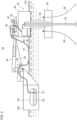
- Fig. 2 is a schematic view of a liquefied carbon dioxide gas injection system 10 according to an embodiment of the present invention.
- the liquefied carbon dioxide gas injection system 10 includes the floating body 12 moored on the ocean 110, a temperature raising and pressure raising facility 18 mounted on the floating body 12, the loading hose 14 connecting the liquefied carbon dioxide gas transport ship 100 and the floating body 12, the flexible riser pipe 16 always connected to the floating body 12, and a gangway 24 bridged between the liquefied carbon dioxide gas transport ship 100 and the floating body 12.
- the liquefied carbon dioxide gas transport ship 100 includes a liquefied carbon dioxide gas storage tank 20 and the gangway 24.
- the liquefied carbon dioxide gas storage tank 20 stores liquefied carbon dioxide gas (liquefied CO 2 ).
- the temperature of the liquefied carbon dioxide gas may be, for example, -10°C to -50°C, and the pressure of the liquefied carbon dioxide gas may be, for example, 2.289 MPa to 0.684 MPa.
- the gangway 24 is a movable connection bridge (telescopic gangway) for allowing workers to come and go between the liquefied carbon dioxide gas transport ship 100 and the floating body 12, and it has moving, ascending, descending, and expanding and contracting functions.
- the gangway 24 is installed on the liquefied carbon dioxide gas transport ship 100.
- the gangway 24 is bridged from the liquefied carbon dioxide gas transport ship 100 to the floating body 12 when the liquefied carbon dioxide gas transport ship 100 approaches the floating body 12.
- the floating body 12 is a simple floating offshore base of an advanced spar (SPAR (cylinder)) type.
- the advanced spar type floating body is characterized by small size and low oscillation.
- the floating body 12 includes an upper hull 30 positioned on the sea, a lower hull 32 positioned in the sea, and a column 34 connecting the upper hull 30 and the lower hull 32.
- the upper hull 30 and the lower hull 32 cancel each other out the pressure of the wave to reduce the oscillation.
- the advanced spar type floating body since the advanced spar type floating body has a draft smaller than that of a normal spar type floating body, the advanced spar type floating body can be built and transported in an upright state and can be installed at a relatively shallow water depth.
- a mooring line 36 extending from the seabed is connected to the lower hull 32.
- the upper hull 30 is provided with a turntable 38 on its upper part, and a loading hose reel 40 and a mooring hose winch 42 are installed on the turntable 38.
- the upper hull 30 of the floating body 12 is provided with the temperature raising and pressure raising facility 18 and a power generation facility 19 that supplies power to the temperature raising and pressure raising facility 18.
- the temperature raising and pressure raising facility 18 is a facility that performs pressure raising for injecting liquefied carbon dioxide gas (for example, of - 10°C/2.289 MPa to -50°C/0.684 MPa) received via the loading hose 14 into the reservoir 114 (see Fig. 1 ) on the seabed, and temperature raising for preventing freezing of surrounding water and blockage due to CO 2 hydrate formation when the liquefied carbon dioxide gas is injected into the reservoir 114.
- liquefied carbon dioxide gas for example, of - 10°C/2.289 MPa to -50°C/0.684 MPa
- the injection pressure varies depending on the depth, permeability, and the like of the reservoir 114, but is typically indicated by "Static Head + 3 MPa to the pressure of the shielding layer" at the injection point.
- Static Head + 3 MPa to the pressure of the shielding layer at the injection point.
- a suitable injection pressure is about 10 MPa to 20 MPa in the wellhead facility 104 on the seabed (see Fig. 1 ).
- the injection temperature of the liquefied carbon dioxide gas is preferably 0°C or more.
- the loading hose 14 is a hose for sending the liquefied carbon dioxide gas 22 stored in the liquefied carbon dioxide gas storage tank 20 in the liquefied carbon dioxide gas transport ship 100 to the temperature raising and pressure raising facility 18 of the floating body 12.
- the loading hose 14 connects the liquefied carbon dioxide gas storage tank 20 and the temperature raising and pressure raising facility 18.
- a hose other than the loading hose 14 may be interposed between the liquefied carbon dioxide gas storage tank 20 and the temperature raising and pressure raising facility 18.
- the liquefied carbon dioxide gas 22 is transferred using a cargo pump 21.
- a drum (not illustrated) for temporarily storing the liquefied carbon dioxide gas 22 from the liquefied carbon dioxide gas storage tank 20 may be disposed in front of the temperature raising and pressure raising facility 18.
- the liquefied carbon dioxide gas whose temperature and pressure have been raised by the temperature raising and pressure raising facility 18 is sent to the wellhead facility 104 on the seabed via the flexible riser pipe 16 and is injected into the reservoir 114.
- One end of the flexible riser pipe 16 is always connected to the upper hull 30 of the floating body 12, and the other end of the flexible riser pipe 16 is connected to the wellhead facility 104 on the seabed (see Fig 1 ).
- a plurality of flexible riser pipes 16 may be disposed as illustrated in Fig. 1 .
- the liquefied carbon dioxide gas transport ship 100 approaches the floating body 12 moored on the ocean. Then, the liquefied carbon dioxide gas transport ship 100 is brought close to a position about 30 m from the floating body 12 by using a mooring hawser 44.
- the gangway 24 provided in the liquefied carbon dioxide gas transport ship 100 is connected to the floating body 12.
- a worker moves from the liquefied carbon dioxide gas transport ship 100 to the floating body 12 via the gangway.
- the loading hose 14 wound around the loading hose reel 40 of the floating body 12 is unreeled and connected to a bow loading system 48 provided in the liquefied carbon dioxide gas transport ship 100.
- the worker who has moved to the floating body 12 activates the power generation facility 19 and the temperature raising and pressure raising facility 18 of the floating body 12.
- the liquefied carbon dioxide gas is sent from the liquefied carbon dioxide gas storage tank 20 to the temperature raising and pressure raising facility 18 via the loading hose 14.
- the temperature raising and pressure raising facility 18 performs temperature raising (about 0°C) and pressure raising (about 10 MPaG) of the received liquefied carbon dioxide gas.
- the liquefied carbon dioxide gas whose temperature and pressure have been raised by the temperature raising and pressure raising facility 18 is sent to the seabed by the flexible riser pipe 16, and injection of the gas into the reservoir 114 is started.
- the worker After the injection of liquefied carbon dioxide gas is started, the worker returns to the liquefied carbon dioxide gas transport ship 100 using the gangway 24.
- the floating body 12 becomes unmanned.
- the gangway 24 is moved away from the floating body 12.
- the liquefied carbon dioxide gas transport ship 100 is moved to a position away from the floating body 12.
- the liquefied carbon dioxide gas transport ship 100 is moored at a position about 100 m to 120 m away from the floating body 12 by the mooring hawser 44.
- the worker inspects the operation status of the facilities, devices, instruments, and the like of the floating body 12.
- the liquefied carbon dioxide gas transport ship 100 is brought close to the floating body, the gangway 24 is connected to the floating body 12, and the worker moves from the liquefied carbon dioxide gas transport ship 100 to the floating body 12 to perform inspection work.
- the worker returns from the floating body 12 to the liquefied carbon dioxide gas transport ship 100.
- the gangway 24 is then removed from the floating body 12 and the liquefied carbon dioxide gas transport ship 100 is moved and moored away from the floating body 12. The same applies to a case where a failure occurs in the facilities and the like of the floating body 12.
- a disengage work is started.
- the liquefied carbon dioxide gas transport ship 100 is brought close to the floating body, the gangway 24 is connected to the floating body 12, and the worker moves from the liquefied carbon dioxide gas transport ship 100 to the floating body 12 to stop the power generation facility 19 and the temperature raising and pressure raising facility 18, and stops the injection of liquefied carbon dioxide gas.
- the loading hose 14 is disconnected from the liquefied carbon dioxide gas transport ship 100 and wound up by the loading hose reel 40 on the turntable 38 of the floating body 12.
- the gangway 24 is moved away from the floating body 12.
- the liquefied carbon dioxide gas transport ship 100 disengages from the floating body 12 using a propulsion device.
- the mooring hawser 44 remains floating on the sea until the next liquefied carbon dioxide gas transport ship 100 arrives.
- the liquefied carbon dioxide gas injection system 10 has been described above.
- the liquefied carbon dioxide gas injection system 10 since the liquefied carbon dioxide gas is directly supplied from the liquefied carbon dioxide gas storage tank 20 of the liquefied carbon dioxide gas transport ship 100 to the temperature raising and pressure raising facility 18 of the floating body 12, it is not necessary to provide a tank for storing the liquefied carbon dioxide gas on the floating body 12.
- the liquefied carbon dioxide gas storage tank 20 originally provided in the liquefied carbon dioxide gas transport ship 100 is used as a storage tank.
- the size of the floating body 12 can be reduced, and the construction cost of the floating body 12 can be significantly reduced.
- an advanced spar type floating body is adopted because the floating body 12 can be downsized. Since the advanced spar type floating body has a characteristic of being less likely to shake in waves, the operation can stably continue with the advanced spar type floating body without stopping the operation of the temperature raising and pressure raising facility 18 even in ocean waves. In addition, since the advanced spar type floating body has low oscillation even in waves, the load applied to a connection portion between the flexible riser pipe 16 and the floating body 12 is reduced. As a result, the service life of the flexible riser pipe 16 can be increased.
- the worker moves from the liquefied carbon dioxide gas transport ship 100 to the floating body 12 using the gangway 24 only when necessary, such as at the time of activation of the temperature raising and pressure raising facility 18, and thus, it is not necessary for the worker to reside on the floating body 12, and it is possible to make the floating body 12 unmanned.
- the facility of the floating body 12 is monitored and operated remotely from the liquefied carbon dioxide gas transport ship 100.
- the construction cost of the floating body 12 can be reduced.
- the oscillation-absorbing gangway facility enables movement of workers without difficulty even in ocean waves.
- the gangway 24 is used for the worker to move from the liquefied carbon dioxide gas transport ship 100 to the floating body 12. Since the transfer under a high wave height is possible as compared with the movement of the worker by a small ship, the efficiency of the connection work of the loading hose and the operation rate of the entire injection work process can improve. In addition, since the risk that the worker is left in the floating body for a long period of time can be reduced, safety can improve.
- the pressure of the liquefied carbon dioxide gas when being transferred from the liquefied carbon dioxide gas transport ship 100 to the floating body 12 can be set to a low pressure (for example, 0.684 MPa to 2.289 MPa). This eliminates the need for attaching and detaching a high-pressure pipe, and thus, workability improves.
- the temperature raising and pressure raising facility 18 is mounted on the floating body 12, it is not necessary to mount a temperature raising and pressure raising facility on the liquefied carbon dioxide gas transport ship 100, and thus, the construction cost of the liquefied carbon dioxide gas transport ship 100 can be significantly reduced.
- the flexible riser pipe 16 which is a high-pressure pipe is always connected to the floating body 12. This eliminates the need for attaching and detaching the flexible riser pipe 16 at the time of starting or ending the injection work of the liquefied carbon dioxide gas into the seabed, and a special and expensive subsea system connecting a transport ship and the seabed is unnecessary, and the work efficiency can improve.
- an advanced spar type floating body is employed as the floating body, but the floating body is not limited to an advanced spar type, and it may be a normal spar type floating body.
- the present invention can be used for carbon capture and storage (CCS).
- CCS carbon capture and storage
Landscapes
- Chemical & Material Sciences (AREA)
- Engineering & Computer Science (AREA)
- Combustion & Propulsion (AREA)
- Mechanical Engineering (AREA)
- Ocean & Marine Engineering (AREA)
- Filling Or Discharging Of Gas Storage Vessels (AREA)
- Physical Or Chemical Processes And Apparatus (AREA)
- Carbon And Carbon Compounds (AREA)
Abstract
Description
- The present invention relates to an injection system and an injection method for liquefied carbon dioxide gas (liquefied CO2) in carbon capture and storage (CCS).
- Carbon capture and storage (CCS) recovers CO2 from a CO2 generation source (for example, combustion exhaust gas from a coal-fired power plant) by a chemical absorption method or the like, compresses and liquefies the CO2, and injects and stores the CO2 in a supercritical state in an underground aquifer (reservoir) shielded by a rock or the like, which is one of global warming countermeasures.
- There are various methods for CCS, and one of them is a liquefied carbon dioxide gas transport and injection method. In this method, the separated and recovered CO2 is compressed and liquefied, temporarily stored in a tank on land in the form of liquefied carbon dioxide gas, loaded on a liquefied carbon dioxide gas transport ship from the tank, and shipped to a storage point. At the storage point, the liquefied carbon dioxide gas is injected from the liquefied carbon dioxide gas transport ship into the aquifer under the seabed (see, for example, Patent Literature 1) .
- Patent Literature 1:
JP2016-84630 A - When the liquefied carbon dioxide gas is injected into the reservoir (aquifer), the liquefied carbon dioxide gas (for example, of -10°C/2.289 MPa to -50°C/0.684 MPa) is pressurized to a predetermined pressure (10 MPa or more), and then the temperature of the gas is raised to 0°C or more to perform injection in order to prevent freezing of surrounding water and to prevent blockage due to CO2 hydrate formation.
- When the liquefied carbon dioxide gas is injected into the seabed after the temperature and pressure are raised on the liquefied carbon dioxide gas transport ship, it is necessary to perform an operation of drawing and connecting a flexible riser pipe for guiding the high-pressure liquefied carbon dioxide gas to the seabed to the transport ship before the start of the injection and removing the pipe from the transport ship after completion of the injection every time the transport ship arrives. However, in the case of this method, there is a problem that the cost for producing, subsea installation, and maintenance of a special subsea system excellent in reliability and durability increases.
- The present invention has been made in view of such a situation, and an object of the present invention is to provide a liquefied carbon dioxide gas injection system and a liquefied carbon dioxide gas injection method capable of injecting liquefied carbon dioxide gas into the seabed at low cost.
- To solve the problem described above, a liquefied carbon dioxide gas injection system according to an aspect of the present invention includes a floating body moored offshore, a temperature raising and pressure raising facility structured to raise a temperature and a pressure of liquefied carbon dioxide gas, the temperature raising and pressurizing facility being mounted on the floating body, a loading hose structured to send liquefied carbon dioxide gas from a liquefied carbon dioxide gas storage tank in a liquefied carbon dioxide gas transport ship to the temperature raising and pressure raising facility of the floating body, and a flexible riser pipe structured to send and inject the liquefied carbon dioxide gas whose temperature and pressure are raised by the temperature raising and pressure raising facility to a seabed, the flexible riser pipe being connected to the floating body. The floating does not have a storage tank for liquefied carbon dioxide gas, and the injection system is under unmanned operation through remotely control from the transport ship.
- Another aspect of the present invention is a liquefied carbon dioxide gas injection method. The method includes approaching a floating body moored offshore by a liquefied carbon dioxide gas transport ship, connecting a gangway provided in the liquefied carbon dioxide gas transport ship to the floating body and transferring a worker from the liquefied carbon dioxide gas transport ship to the floating body, connecting a liquefied carbon dioxide gas storage tank in the liquefied carbon dioxide gas transport ship and a temperature raising and pressure raising facility mounted on the floating body with a loading hose, sending liquefied carbon dioxide gas from the liquefied carbon dioxide gas storage tank to the temperature raising and pressure raising facility via the loading hose, raising the temperature and the pressure of the liquefied carbon dioxide gas with the temperature raising and pressure raising facility, and sending and injecting the liquefied carbon dioxide gas whose temperature and pressure are raised to a seabed with a flexible riser pipe.
- The present invention can provide a liquefied carbon dioxide gas injection system and a liquefied carbon dioxide gas injection method capable of injecting liquefied carbon dioxide gas into the seabed at low cost.
-
- [
Fig. 1] Fig. 1 is a diagram illustrating a schematic flow of CCS in which a liquefied carbon dioxide gas injection system according to an embodiment of the present invention is used. - [
Fig. 2] Fig. 2 is a schematic view of a liquefied carbon dioxide gas injection system according to an embodiment of the present invention. - Hereinafter, the present invention will be described based on a preferred embodiment with reference to the drawings. The following configurations are intended to be illustrative for an understanding of the present disclosure, and the scope of the present disclosure is defined only by the appended claims. The same or equivalent components and members illustrated in the respective drawings are denoted by the same reference numerals, and redundant description will be omitted as appropriate. The dimensions of the members in each drawing are appropriately enlarged and reduced to facilitate understanding. In each drawing, some members that are not important for describing the embodiment are omitted.
-
Fig. 1 is a diagram illustrating a schematic flow of CCS in which a liquefied carbon dioxide gas injection system according to an embodiment of the present invention is used.Fig. 1 illustrates CCS of a liquefied carbon dioxide gas transport and injection system. - In CCS, CO2 is separated and recovered from a CO2 generation source such as combustion exhaust gas of a coal-fired power plant by using a chemical absorption method or the like, for example. Thereafter, the CO2 recovered by a compression/
liquefaction device 101 is compressed and liquefied, then stored in atank 102 on land in the form of liquefied carbon dioxide gas. The liquefied carbon dioxide gas is loaded onto a liquefied carbon dioxidegas transport ship 100 from thetank 102 by using aloading arm 103, and is transported by ship to a floatingbody 12 moored on anocean 110. - The liquefied carbon dioxide gas loaded on the liquefied carbon dioxide
gas transport ship 100 is sent to a temperature raising and pressure raising facility mounted on the floatingbody 12 by aloading hose 14. The liquefied carbon dioxide gas whose temperature and pressure have been raised by the temperature raising and pressure raising facility is sent to awellhead facility 104 installed on aseabed 112 via aflexible riser pipe 16. The liquefied carbon dioxide gas is injected into areservoir 114 below the seabed by thewellhead facility 104. -
Fig. 2 is a schematic view of a liquefied carbon dioxidegas injection system 10 according to an embodiment of the present invention. The liquefied carbon dioxidegas injection system 10 includes the floatingbody 12 moored on theocean 110, a temperature raising andpressure raising facility 18 mounted on the floatingbody 12, theloading hose 14 connecting the liquefied carbon dioxidegas transport ship 100 and the floatingbody 12, theflexible riser pipe 16 always connected to thefloating body 12, and agangway 24 bridged between the liquefied carbon dioxidegas transport ship 100 and the floatingbody 12. - The liquefied carbon dioxide
gas transport ship 100 includes a liquefied carbon dioxidegas storage tank 20 and thegangway 24. The liquefied carbon dioxidegas storage tank 20 stores liquefied carbon dioxide gas (liquefied CO2). The temperature of the liquefied carbon dioxide gas may be, for example, -10°C to -50°C, and the pressure of the liquefied carbon dioxide gas may be, for example, 2.289 MPa to 0.684 MPa. - The
gangway 24 is a movable connection bridge (telescopic gangway) for allowing workers to come and go between the liquefied carbon dioxidegas transport ship 100 and thefloating body 12, and it has moving, ascending, descending, and expanding and contracting functions. Thegangway 24 is installed on the liquefied carbon dioxidegas transport ship 100. Thegangway 24 is bridged from the liquefied carbon dioxidegas transport ship 100 to the floatingbody 12 when the liquefied carbon dioxidegas transport ship 100 approaches thefloating body 12. - The
floating body 12 is a simple floating offshore base of an advanced spar (SPAR (cylinder)) type. The advanced spar type floating body is characterized by small size and low oscillation. Thefloating body 12 includes anupper hull 30 positioned on the sea, alower hull 32 positioned in the sea, and acolumn 34 connecting theupper hull 30 and thelower hull 32. In the advanced spar type floating body, theupper hull 30 and thelower hull 32 cancel each other out the pressure of the wave to reduce the oscillation. In addition, since the advanced spar type floating body has a draft smaller than that of a normal spar type floating body, the advanced spar type floating body can be built and transported in an upright state and can be installed at a relatively shallow water depth. - As illustrated in
Fig. 2 , amooring line 36 extending from the seabed is connected to thelower hull 32. Theupper hull 30 is provided with aturntable 38 on its upper part, and aloading hose reel 40 and amooring hose winch 42 are installed on theturntable 38. - The
upper hull 30 of the floatingbody 12 is provided with the temperature raising andpressure raising facility 18 and apower generation facility 19 that supplies power to the temperature raising andpressure raising facility 18. The temperature raising andpressure raising facility 18 is a facility that performs pressure raising for injecting liquefied carbon dioxide gas (for example, of - 10°C/2.289 MPa to -50°C/0.684 MPa) received via theloading hose 14 into the reservoir 114 (seeFig. 1 ) on the seabed, and temperature raising for preventing freezing of surrounding water and blockage due to CO2 hydrate formation when the liquefied carbon dioxide gas is injected into thereservoir 114. - Here, the injection conditions of the liquefied carbon dioxide gas in the CCS will be described.
- The injection pressure varies depending on the depth, permeability, and the like of the
reservoir 114, but is typically indicated by "Static Head + 3 MPa to the pressure of the shielding layer" at the injection point. In the case of CCS in thereservoir 114 in the seabed, in consideration of the injection depth, the density of liquefied carbon dioxide gas, and the pressure loss in the wellbore, a suitable injection pressure is about 10 MPa to 20 MPa in thewellhead facility 104 on the seabed (seeFig. 1 ). - When the liquefied carbon dioxide gas is injected into the
reservoir 114, it is necessary to increase the temperature and perform the injection to prevent freezing of surrounding water (0°C or more) and blockage due to CO2 hydrate formation (5°C or less). Considering that blockage due to CO2 hydrate formation does not occur at the time of injection at 0°C in an actual example of the past CCS, the injection temperature of the liquefied carbon dioxide gas is preferably 0°C or more. - The
loading hose 14 is a hose for sending the liquefiedcarbon dioxide gas 22 stored in the liquefied carbon dioxidegas storage tank 20 in the liquefied carbon dioxidegas transport ship 100 to the temperature raising andpressure raising facility 18 of thefloating body 12. Theloading hose 14 connects the liquefied carbon dioxidegas storage tank 20 and the temperature raising andpressure raising facility 18. A hose other than theloading hose 14 may be interposed between the liquefied carbon dioxidegas storage tank 20 and the temperature raising andpressure raising facility 18. The liquefiedcarbon dioxide gas 22 is transferred using acargo pump 21. A drum (not illustrated) for temporarily storing the liquefiedcarbon dioxide gas 22 from the liquefied carbon dioxidegas storage tank 20 may be disposed in front of the temperature raising andpressure raising facility 18. - The liquefied carbon dioxide gas whose temperature and pressure have been raised by the temperature raising and
pressure raising facility 18 is sent to thewellhead facility 104 on the seabed via theflexible riser pipe 16 and is injected into thereservoir 114. One end of theflexible riser pipe 16 is always connected to theupper hull 30 of the floatingbody 12, and the other end of theflexible riser pipe 16 is connected to thewellhead facility 104 on the seabed (seeFig 1 ). Although oneflexible riser pipe 16 is illustrated inFig. 2 , a plurality offlexible riser pipes 16 may be disposed as illustrated inFig. 1 . - Next, a method for injecting liquefied carbon dioxide gas using the liquefied carbon dioxide
gas injection system 10 will be described. - First, the liquefied carbon dioxide
gas transport ship 100 approaches the floatingbody 12 moored on the ocean. Then, the liquefied carbon dioxidegas transport ship 100 is brought close to a position about 30 m from the floatingbody 12 by using amooring hawser 44. - Next, the gangway 24 provided in the liquefied carbon dioxide
gas transport ship 100 is connected to the floatingbody 12. A worker moves from the liquefied carbon dioxidegas transport ship 100 to the floatingbody 12 via the gangway. - Next, the
loading hose 14 wound around theloading hose reel 40 of the floatingbody 12 is unreeled and connected to abow loading system 48 provided in the liquefied carbon dioxidegas transport ship 100. This causes the liquefied carbon dioxidegas storage tank 20 in the liquefied carbon dioxidegas transport ship 100 to be connected to the temperature raising andpressure raising facility 18 mounted on the floatingbody 12. - The worker who has moved to the floating
body 12 activates thepower generation facility 19 and the temperature raising andpressure raising facility 18 of the floatingbody 12. The liquefied carbon dioxide gas is sent from the liquefied carbon dioxidegas storage tank 20 to the temperature raising andpressure raising facility 18 via theloading hose 14. The temperature raising andpressure raising facility 18 performs temperature raising (about 0°C) and pressure raising (about 10 MPaG) of the received liquefied carbon dioxide gas. The liquefied carbon dioxide gas whose temperature and pressure have been raised by the temperature raising andpressure raising facility 18 is sent to the seabed by theflexible riser pipe 16, and injection of the gas into thereservoir 114 is started. - After the injection of liquefied carbon dioxide gas is started, the worker returns to the liquefied carbon dioxide
gas transport ship 100 using thegangway 24. The floatingbody 12 becomes unmanned. After the worker returns to the liquefied carbon dioxidegas transport ship 100, thegangway 24 is moved away from the floatingbody 12. Then, the liquefied carbon dioxidegas transport ship 100 is moved to a position away from the floatingbody 12. The liquefied carbon dioxidegas transport ship 100 is moored at a position about 100 m to 120 m away from the floatingbody 12 by themooring hawser 44. - Thereafter, a steady injection operation of liquefied carbon dioxide gas is started. Until the injection of the liquefied
carbon dioxide gas 22 stored in the liquefied carbon dioxidegas storage tank 20 of the liquefied carbon dioxidegas transport ship 100 into the seabed is completed, thepower generation facility 19 and the temperature raising andpressure raising facility 18 of the floatingbody 12 are under unmanned operation, and they are monitored and operated remotely from the liquefied carbon dioxidegas transport ship 100. - At regular time intervals (8 to 12 hours), the worker inspects the operation status of the facilities, devices, instruments, and the like of the floating
body 12. At the time of inspection, the liquefied carbon dioxidegas transport ship 100 is brought close to the floating body, thegangway 24 is connected to the floatingbody 12, and the worker moves from the liquefied carbon dioxidegas transport ship 100 to the floatingbody 12 to perform inspection work. After completion of the inspection work, the worker returns from the floatingbody 12 to the liquefied carbon dioxidegas transport ship 100. The gangway 24 is then removed from the floatingbody 12 and the liquefied carbon dioxidegas transport ship 100 is moved and moored away from the floatingbody 12. The same applies to a case where a failure occurs in the facilities and the like of the floatingbody 12. - After completion of the injection of the entire amount of the liquefied
carbon dioxide gas 22 stored in the liquefied carbon dioxidegas storage tank 20 into the seabed, a disengage work is started. The liquefied carbon dioxidegas transport ship 100 is brought close to the floating body, thegangway 24 is connected to the floatingbody 12, and the worker moves from the liquefied carbon dioxidegas transport ship 100 to the floatingbody 12 to stop thepower generation facility 19 and the temperature raising andpressure raising facility 18, and stops the injection of liquefied carbon dioxide gas. Thereafter, theloading hose 14 is disconnected from the liquefied carbon dioxidegas transport ship 100 and wound up by theloading hose reel 40 on theturntable 38 of the floatingbody 12. After the worker returns to the liquefied carbon dioxidegas transport ship 100, thegangway 24 is moved away from the floatingbody 12. After themooring hawser 44 is disconnected from the liquefied carbon dioxidegas transport ship 100, the liquefied carbon dioxidegas transport ship 100 disengages from the floatingbody 12 using a propulsion device. Themooring hawser 44 remains floating on the sea until the next liquefied carbon dioxidegas transport ship 100 arrives. - The liquefied carbon dioxide
gas injection system 10 according to an embodiment of the present invention has been described above. In the liquefied carbon dioxidegas injection system 10 according to the present embodiment, since the liquefied carbon dioxide gas is directly supplied from the liquefied carbon dioxidegas storage tank 20 of the liquefied carbon dioxidegas transport ship 100 to the temperature raising andpressure raising facility 18 of the floatingbody 12, it is not necessary to provide a tank for storing the liquefied carbon dioxide gas on the floatingbody 12. In other words, the liquefied carbon dioxidegas storage tank 20 originally provided in the liquefied carbon dioxidegas transport ship 100 is used as a storage tank. Thus, the size of the floatingbody 12 can be reduced, and the construction cost of the floatingbody 12 can be significantly reduced. - In the liquefied carbon dioxide
gas injection system 10 according to the present embodiment, an advanced spar type floating body is adopted because the floatingbody 12 can be downsized. Since the advanced spar type floating body has a characteristic of being less likely to shake in waves, the operation can stably continue with the advanced spar type floating body without stopping the operation of the temperature raising andpressure raising facility 18 even in ocean waves. In addition, since the advanced spar type floating body has low oscillation even in waves, the load applied to a connection portion between theflexible riser pipe 16 and the floatingbody 12 is reduced. As a result, the service life of theflexible riser pipe 16 can be increased. - In addition, in the liquefied carbon dioxide
gas injection system 10 according to the present embodiment, the worker moves from the liquefied carbon dioxidegas transport ship 100 to the floatingbody 12 using the gangway 24 only when necessary, such as at the time of activation of the temperature raising andpressure raising facility 18, and thus, it is not necessary for the worker to reside on the floatingbody 12, and it is possible to make the floatingbody 12 unmanned. After the steady injection operation is started, the facility of the floatingbody 12 is monitored and operated remotely from the liquefied carbon dioxidegas transport ship 100. As a result, it is not necessary to provide a facility (living facility or the like) for the worker to reside on the floatingbody 12, and the construction cost of the floatingbody 12 can be reduced. In addition, since the necessity of a resident on the floatingbody 12 is eliminated, it is possible to reduce labor costs, and thus, it is possible to further reduce costs. The oscillation-absorbing gangway facility enables movement of workers without difficulty even in ocean waves. - In the liquefied carbon dioxide
gas injection system 10 according to the present embodiment, thegangway 24 is used for the worker to move from the liquefied carbon dioxidegas transport ship 100 to the floatingbody 12. Since the transfer under a high wave height is possible as compared with the movement of the worker by a small ship, the efficiency of the connection work of the loading hose and the operation rate of the entire injection work process can improve. In addition, since the risk that the worker is left in the floating body for a long period of time can be reduced, safety can improve. - In addition, in the liquefied carbon dioxide
gas injection system 10 according to the present embodiment, since the temperature raising andpressure raising facility 18 is mounted on the floatingbody 12, the pressure of the liquefied carbon dioxide gas when being transferred from the liquefied carbon dioxidegas transport ship 100 to the floatingbody 12 can be set to a low pressure (for example, 0.684 MPa to 2.289 MPa). This eliminates the need for attaching and detaching a high-pressure pipe, and thus, workability improves. In addition, since the temperature raising andpressure raising facility 18 is mounted on the floatingbody 12, it is not necessary to mount a temperature raising and pressure raising facility on the liquefied carbon dioxidegas transport ship 100, and thus, the construction cost of the liquefied carbon dioxidegas transport ship 100 can be significantly reduced. - In the liquefied carbon dioxide
gas injection system 10 according to the present embodiment, theflexible riser pipe 16 which is a high-pressure pipe is always connected to the floatingbody 12. This eliminates the need for attaching and detaching theflexible riser pipe 16 at the time of starting or ending the injection work of the liquefied carbon dioxide gas into the seabed, and a special and expensive subsea system connecting a transport ship and the seabed is unnecessary, and the work efficiency can improve. - The present invention has been described above based on an Example. It is to be understood by those skilled in the art that the Example is an example, various modifications can be made to the combination of each component and each processing process, and such modifications are also within the scope of the present invention.
- For example, in the above-described embodiment, an advanced spar type floating body is employed as the floating body, but the floating body is not limited to an advanced spar type, and it may be a normal spar type floating body.
- The present invention can be used for carbon capture and storage (CCS).
- 10 liquefied carbon dioxide gas injection system, 12 floating body, 14 loading hose, 16 flexible riser pipe, 18 temperature raising and pressure raising facility, 19 power generation facility, 20 liquefied carbon dioxide gas storage tank, 21 cargo pump, 22 liquefied carbon dioxide gas, 24 gangway, 30 upper hull, 32 lower hull, 34 column, 36 mooring line, 38 turntable, 40 loading hose reel, 42 mooring hawser winch, 44 mooring hawser, 48 bow loading system, 100 liquefied carbon dioxide gas transport ship, 101 compression/liquidation device, 102 tank, 103 loading arm, 104 wellhead facility
Claims (6)
- A liquefied carbon dioxide gas injection system comprising:a floating body moored offshore;a temperature raising and pressure raising facility structured to raise a temperature and a pressure of liquefied carbon dioxide gas, the temperature raising and pressurizing facility being mounted on the floating body;a loading hose structured to send liquefied carbon dioxide gas from a liquefied carbon dioxide gas storage tank in a liquefied carbon dioxide gas transport ship to the temperature raising and pressure raising facility of the floating body; anda flexible riser pipe structured to send and inject the liquefied carbon dioxide gas whose temperature and pressure are raised by the temperature raising and pressure raising facility to a seabed, the flexible riser pipe being connected to the floating body.
- The liquefied carbon dioxide gas injection system according to claim 1, wherein the floating body is an advanced spar type floating body and does not have a storage tank for liquefied carbon dioxide gas.
- The liquefied carbon dioxide gas injection system according to claim 1 or 2, wherein the temperature raising and pressure raising facility mounted on the floating body is under unmanned operation through remote control from the liquefied carbon dioxide gas transport ship, and the floating body is not provided with a residential facility for a worker.
- The liquefied carbon dioxide gas injection system according to any one of claims 1 to 3, further comprising a gangway that allows a worker to come and go between the liquefied carbon dioxide gas transport ship and the floating body.
- The liquefied carbon dioxide gas injection system according to any one of claims 1 to 4, wherein the flexible riser pipe is always connected to the floating body.
- A liquefied carbon dioxide gas injection method comprising:approaching a floating body moored offshore by a liquefied carbon dioxide gas transport ship;connecting a gangway provided in the liquefied carbon dioxide gas transport ship to the floating body and transferring a worker from the liquefied carbon dioxide gas transport ship to the floating body;connecting a liquefied carbon dioxide gas storage tank in the liquefied carbon dioxide gas transport ship and a temperature raising and pressure raising facility mounted on the floating body with a loading hose;sending liquefied carbon dioxide gas from the liquefied carbon dioxide gas storage tank to the temperature raising and pressure raising facility via the loading hose;raising the temperature and the pressure of the liquefied carbon dioxide gas with the temperature raising and pressure raising facility; andsending and injecting the liquefied carbon dioxide gas whose temperature and pressure are raised to a seabed with a flexible riser pipe.
Applications Claiming Priority (2)
| Application Number | Priority Date | Filing Date | Title |
|---|---|---|---|
| JP2021097626A JP7803657B2 (en) | 2021-06-10 | 2021-06-10 | Liquefied carbon dioxide gas injection system and liquefied carbon dioxide gas injection method |
| PCT/JP2022/023261 WO2022260122A1 (en) | 2021-06-10 | 2022-06-09 | Liquefied carbon dioxide press-fitting system and liquefied carbon dioxide press-fitting method |
Publications (2)
| Publication Number | Publication Date |
|---|---|
| EP4353582A1 true EP4353582A1 (en) | 2024-04-17 |
| EP4353582A4 EP4353582A4 (en) | 2025-07-30 |
Family
ID=84424570
Family Applications (1)
| Application Number | Title | Priority Date | Filing Date |
|---|---|---|---|
| EP22820301.4A Pending EP4353582A4 (en) | 2021-06-10 | 2022-06-09 | Press fitting system for liquefied carbon dioxide and press fitting process for liquefied carbon dioxide |
Country Status (4)
| Country | Link |
|---|---|
| EP (1) | EP4353582A4 (en) |
| JP (1) | JP7803657B2 (en) |
| AU (1) | AU2022289804B2 (en) |
| WO (1) | WO2022260122A1 (en) |
Families Citing this family (2)
| Publication number | Priority date | Publication date | Assignee | Title |
|---|---|---|---|---|
| EP4500069A1 (en) * | 2022-03-30 | 2025-02-05 | Stena Power & Lng Solutions As | Offshore carbon capture and injection method and system |
| CN119825302B (en) * | 2024-12-19 | 2026-01-23 | 大连船舶重工集团有限公司 | Marine carbon sealing method |
Family Cites Families (11)
| Publication number | Priority date | Publication date | Assignee | Title |
|---|---|---|---|---|
| JP2003072675A (en) | 2001-09-04 | 2003-03-12 | Mitsubishi Heavy Ind Ltd | Hydrogen recovery system with hydrogen production plant |
| US6973948B2 (en) * | 2003-09-19 | 2005-12-13 | Sbm-Imodco, Inc. | Gas offloading system |
| KR20110016250A (en) * | 2009-08-11 | 2011-02-17 | 한국해양연구원 | Liquefied CO2 Transporter Combines Pusher Vessel and Tank Pant Concept |
| KR20110072810A (en) * | 2009-12-23 | 2011-06-29 | 대우조선해양 주식회사 | CO2 capture and storage process by ship |
| JP2012132141A (en) | 2010-12-17 | 2012-07-12 | Mitsubishi Heavy Ind Ltd | Columnar structure and method of extending columnar structure at sea bottom |
| US20140299039A1 (en) * | 2011-08-18 | 2014-10-09 | Stamicarbon B.V. | Shipping method for co2 storage and import of cng |
| JP2016084630A (en) | 2014-10-27 | 2016-05-19 | 三菱重工業株式会社 | Riser pipe device, riser pipe lifting system and riser pipe lifting method |
| KR20160141532A (en) * | 2015-06-01 | 2016-12-09 | 대우조선해양 주식회사 | Natural gas incoming system of flng and incoming method of natural gas |
| KR20170139846A (en) * | 2016-06-10 | 2017-12-20 | 대우조선해양 주식회사 | Offshore plant |
| WO2018234721A1 (en) * | 2017-06-21 | 2018-12-27 | Mirade Consultants Ltd | METHOD AND APPARATUS FOR ASSISTED RECOVERY OF CO2 BASED OIL AT SEA |
| JP7266447B2 (en) | 2019-04-09 | 2023-04-28 | 三菱重工業株式会社 | Offshore installation method of wind turbine using semi-submersible floating body and semi-submersible floating body |
-
2021
- 2021-06-10 JP JP2021097626A patent/JP7803657B2/en active Active
-
2022
- 2022-06-09 WO PCT/JP2022/023261 patent/WO2022260122A1/en not_active Ceased
- 2022-06-09 EP EP22820301.4A patent/EP4353582A4/en active Pending
- 2022-06-09 AU AU2022289804A patent/AU2022289804B2/en active Active
Also Published As
| Publication number | Publication date |
|---|---|
| EP4353582A4 (en) | 2025-07-30 |
| AU2022289804B2 (en) | 2025-07-10 |
| AU2022289804A1 (en) | 2024-01-25 |
| WO2022260122A1 (en) | 2022-12-15 |
| JP7803657B2 (en) | 2026-01-21 |
| JP2022189193A (en) | 2022-12-22 |
Similar Documents
| Publication | Publication Date | Title |
|---|---|---|
| AU2007275960B2 (en) | System and vessel hydrocarbon production and method for intervention on subsea equipment | |
| AU2022289804A1 (en) | Liquefied carbon dioxide press-fitting system and liquefied carbon dioxide press-fitting method | |
| EP4240937B1 (en) | Subsea fluid handling system and method for long term storage of fluids in a subterranean void | |
| US12140001B2 (en) | Buoy for injecting fluid in a subterranean void and methods for connecting and disconnecting a fluid passage from a vessel to the buoy | |
| US7426963B2 (en) | Piggable flowline-riser system | |
| AU2021400933B2 (en) | A ship and a method for bringing liquified gas from an onshore terminal across a sea to a subsurface permanent storage reservoir | |
| KR20110123056A (en) | Liquefied Carbon Dioxide Transport with Underground Storage | |
| KR20100065828A (en) | Floating storage unit for storaging carbon dioxide and operating method of the unit | |
| EP4298311B1 (en) | Fluid injection system and related methods | |
| KR102426330B1 (en) | Movable subsea carbon dioxide storage system | |
| US6012530A (en) | Method and apparatus for producing and shipping hydrocarbons offshore | |
| KR20140130995A (en) | Installation Method Of Test Module For Ship | |
| CN217148567U (en) | Emergency rapid transportation system for shipborne liquid medium | |
| KR20140130996A (en) | Gas Test Method Of Ship On Near-shore | |
| NO347106B1 (en) | Buoy for Injecting Fluid in a Subterranean Void and Methods for Connecting and Disconnecting a Fluid Passage from a Vessel to the Buoy | |
| CA3197792C (en) | Subsea fluid handling system and method for long term storage of fluids in a subterranean void | |
| CN220436252U (en) | Offshore CO2 remote relay supercharging system | |
| JP2025529089A (en) | carbon dioxide injection | |
| JPH03213490A (en) | Crude oil storage and shipping equipment | |
| DeJong et al. | Development and Utilization of a Deepwater Pipeline Connector | |
| KR102130714B1 (en) | Test Method Of Liquefaction Process For Ship | |
| WO2024248620A1 (en) | An injection buoy, a system, and a method for preventing formation of an ice plug in an injection hose | |
| CN114348950A (en) | A shipborne liquid medium emergency quick transfer system | |
| English | ABOUT THE ONE-ATMOSPHERE MANIFOLD CENTER |
Legal Events
| Date | Code | Title | Description |
|---|---|---|---|
| STAA | Information on the status of an ep patent application or granted ep patent |
Free format text: STATUS: THE INTERNATIONAL PUBLICATION HAS BEEN MADE |
|
| PUAI | Public reference made under article 153(3) epc to a published international application that has entered the european phase |
Free format text: ORIGINAL CODE: 0009012 |
|
| STAA | Information on the status of an ep patent application or granted ep patent |
Free format text: STATUS: REQUEST FOR EXAMINATION WAS MADE |
|
| 17P | Request for examination filed |
Effective date: 20240110 |
|
| AK | Designated contracting states |
Kind code of ref document: A1 Designated state(s): AL AT BE BG CH CY CZ DE DK EE ES FI FR GB GR HR HU IE IS IT LI LT LU LV MC MK MT NL NO PL PT RO RS SE SI SK SM TR |
|
| DAV | Request for validation of the european patent (deleted) | ||
| DAX | Request for extension of the european patent (deleted) | ||
| A4 | Supplementary search report drawn up and despatched |
Effective date: 20250702 |
|
| RIC1 | Information provided on ipc code assigned before grant |
Ipc: B63B 35/44 20060101AFI20250626BHEP Ipc: B63B 27/30 20060101ALI20250626BHEP Ipc: B63B 27/24 20060101ALI20250626BHEP |