EP4353526A2 - Vorrichtung zur einschränkung der aktuatorbewegung während eines dynamischen ereignisses - Google Patents
Vorrichtung zur einschränkung der aktuatorbewegung während eines dynamischen ereignisses Download PDFInfo
- Publication number
- EP4353526A2 EP4353526A2 EP23201921.6A EP23201921A EP4353526A2 EP 4353526 A2 EP4353526 A2 EP 4353526A2 EP 23201921 A EP23201921 A EP 23201921A EP 4353526 A2 EP4353526 A2 EP 4353526A2
- Authority
- EP
- European Patent Office
- Prior art keywords
- actuator
- rotational motion
- clip
- seat
- dynamic event
- Prior art date
- Legal status (The legal status is an assumption and is not a legal conclusion. Google has not performed a legal analysis and makes no representation as to the accuracy of the status listed.)
- Pending
Links
Images


Classifications
-
- B—PERFORMING OPERATIONS; TRANSPORTING
- B60—VEHICLES IN GENERAL
- B60N—SEATS SPECIALLY ADAPTED FOR VEHICLES; VEHICLE PASSENGER ACCOMMODATION NOT OTHERWISE PROVIDED FOR
- B60N2/00—Seats specially adapted for vehicles; Arrangement or mounting of seats in vehicles
- B60N2/02—Seats specially adapted for vehicles; Arrangement or mounting of seats in vehicles the seat or part thereof being movable, e.g. adjustable
- B60N2/0224—Non-manual adjustments, e.g. with electrical operation
- B60N2/02246—Electric motors therefor
- B60N2/02253—Electric motors therefor characterised by the transmission between the electric motor and the seat or seat parts
-
- B—PERFORMING OPERATIONS; TRANSPORTING
- B60—VEHICLES IN GENERAL
- B60N—SEATS SPECIALLY ADAPTED FOR VEHICLES; VEHICLE PASSENGER ACCOMMODATION NOT OTHERWISE PROVIDED FOR
- B60N2/00—Seats specially adapted for vehicles; Arrangement or mounting of seats in vehicles
- B60N2/02—Seats specially adapted for vehicles; Arrangement or mounting of seats in vehicles the seat or part thereof being movable, e.g. adjustable
- B60N2/0224—Non-manual adjustments, e.g. with electrical operation
- B60N2/02246—Electric motors therefor
-
- B—PERFORMING OPERATIONS; TRANSPORTING
- B60—VEHICLES IN GENERAL
- B60N—SEATS SPECIALLY ADAPTED FOR VEHICLES; VEHICLE PASSENGER ACCOMMODATION NOT OTHERWISE PROVIDED FOR
- B60N2/00—Seats specially adapted for vehicles; Arrangement or mounting of seats in vehicles
- B60N2/02—Seats specially adapted for vehicles; Arrangement or mounting of seats in vehicles the seat or part thereof being movable, e.g. adjustable
- B60N2/22—Seats specially adapted for vehicles; Arrangement or mounting of seats in vehicles the seat or part thereof being movable, e.g. adjustable the back-rest being adjustable
- B60N2/23—Seats specially adapted for vehicles; Arrangement or mounting of seats in vehicles the seat or part thereof being movable, e.g. adjustable the back-rest being adjustable by linear actuators, e.g. linear screw mechanisms
- B60N2/233—Seats specially adapted for vehicles; Arrangement or mounting of seats in vehicles the seat or part thereof being movable, e.g. adjustable the back-rest being adjustable by linear actuators, e.g. linear screw mechanisms by linear screw mechanisms
-
- B—PERFORMING OPERATIONS; TRANSPORTING
- B60—VEHICLES IN GENERAL
- B60N—SEATS SPECIALLY ADAPTED FOR VEHICLES; VEHICLE PASSENGER ACCOMMODATION NOT OTHERWISE PROVIDED FOR
- B60N2/00—Seats specially adapted for vehicles; Arrangement or mounting of seats in vehicles
- B60N2/24—Seats specially adapted for vehicles; Arrangement or mounting of seats in vehicles for particular purposes or particular vehicles
- B60N2/42—Seats specially adapted for vehicles; Arrangement or mounting of seats in vehicles for particular purposes or particular vehicles the seat constructed to protect the occupant from the effect of abnormal g-forces, e.g. crash or safety seats
- B60N2/427—Seats or parts thereof displaced during a crash
- B60N2/42727—Seats or parts thereof displaced during a crash involving substantially rigid displacement
- B60N2/42745—Seats or parts thereof displaced during a crash involving substantially rigid displacement of the back-rest
-
- B—PERFORMING OPERATIONS; TRANSPORTING
- B60—VEHICLES IN GENERAL
- B60N—SEATS SPECIALLY ADAPTED FOR VEHICLES; VEHICLE PASSENGER ACCOMMODATION NOT OTHERWISE PROVIDED FOR
- B60N2/00—Seats specially adapted for vehicles; Arrangement or mounting of seats in vehicles
- B60N2/24—Seats specially adapted for vehicles; Arrangement or mounting of seats in vehicles for particular purposes or particular vehicles
- B60N2/42—Seats specially adapted for vehicles; Arrangement or mounting of seats in vehicles for particular purposes or particular vehicles the seat constructed to protect the occupant from the effect of abnormal g-forces, e.g. crash or safety seats
- B60N2/433—Safety locks for back-rests, e.g. with locking bars activated by inertia
Definitions
- the present disclosure relates generally to devices for reducing component deformation during a dynamic event, and more particularly to devices for constraining actuator motion during a dynamic event to minimize actuator deformation.
- Passenger seats such as aircraft passenger seats commonly include actuators for changing seat component angles as well as driving seat component extension and translation.
- actuators may be used to drive seat back recline, leg rest deployment, leg rest extension, lateral seat motion, etc.
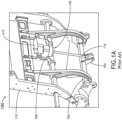
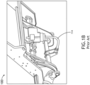
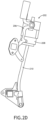
- an exemplary business class passenger seat frame 100 may include a linear actuator 102 configured to drive seat back recline.
- the actuator 102 is shown coupled at one end to a frame member 104 located in the seat pan 106 and at an opposing end to a frame member 108 located in the seat back 110.
- a stepper motor 112 is energized to drive rotation of a lead screw 114 or shaft, terms which are considered synonymous for purposes of this disclosure.
- the seat back 110 In use, rotating the lead screw 114 in a first direction causes the seat back 110 to pivot forward to incline the seat back, whereas rotating the lead screw 114 in a second direction, opposite the first direction, causes the seat back 110 to pivot rearward to recline the seat back 110.
- the seat back 110 under the control of the actuator 102, may adjust between an upright sitting position for taxi, takeoff, and landing (TTOL) and a fully reclined position during flight, through various intermediate sitting positions.
- TTOL taxi, takeoff, and landing
- the present disclosure provides a device for constraining rotational motion of an actuator during a dynamic event such as a high g-force event.
- the device includes a first part attachable to a frame member such as a seat pan frame member.
- the first part carries a first clip.
- the device further includes a second part attachable to an actuator proximate one end of the actuator.
- the second part carries a second clip.
- the first clip and the second clip are disengaged.
- the second clip is configured to engage the first clip to momentarily stop rotational motion of the actuator, for instance during rebound motion.
- the first part includes an opening configured to receive a transverse frame member therethrough and a mechanical stop configured to limit rotational motion of the actuator in a forward direction.
- the first clip includes a first hook extending in a first direction
- the second clip includes a second hook extending in a second direction opposite the first direction
- the first and second hooks are configured to pass each other during the dynamic event sufficient to cause actuator rotational motion.
- the second hook may move past the first hook during a first rotational movement of the actuator and the first and second hooks may momentarily engage during a second rotational movement of the actuator, wherein the first and second rotational movements are in opposite directions.
- the second part includes an annular collar configured to be received around a shaft of the actuator, and the second hook is formed on a radial extension of the annular collar.
- the dynamic event sufficient to cause actuator rotational motion is an event of predetermined magnitude, for instance at least a 2 g-force event, at least a 12 g-force event, at least a 16 g-force event, or at least a 20 g-force event.
- the present disclosure provides a passenger seat including a seat pan and a seat back rotationally coupled to the seat pan.
- An actuator coupled at a first end to the seat pan and at a second end to the seat back is operable to control rotational motion of the seat back relative to the seat pan.
- the actuator includes a shaft.
- a device configured to constrain rotational motion of the actuator during a dynamic event includes a first part attached to the seat pan carrying a first clip and a second part attached to the actuator proximate the first end and carrying a second clip. Prior to and following a dynamic event sufficient to cause actuator rotational motion the first clip and the second clip are disengaged. During a dynamic event sufficient to cause actuator rotational motion the second clip is configured to engage the first clip to momentarily stop rotational motion of the actuator such that load on the actuator can pass to the seat frame.
- the first part includes an opening receiving a transverse frame member of the seat pan therethrough, and a mechanical stop configured to limit rotational motion of the actuator in a forward direction relative to the seat pan.
- the first clip includes a first hook extending in a first direction
- the second clip includes a second hook extending in a second direction opposite the first direction
- the first and second hooks are configured to pass each other as the actuator rotates in a forward direction of the seat pan during the dynamic event sufficient to cause actuator rotational motion.
- the second part includes an annular collar configured to be received around the shaft of the actuator, and the second hook is formed on a radial extension of the annular collar.
- the dynamic event sufficient to cause actuator rotational motion is an event of magnitude sufficient to cause deformation to a seat element.
- the actuator is a linear actuator including a stepper motor and a lead screw, wherein the second clip surrounds a portion of the lead screw.
- the present disclosure provides a passenger seat including a seat pan including a transverse frame member and a seat back rotationally coupled to the seat pan.
- An actuator coupled at a first end to the seat pan and at a second end to the seat back is operable to control rotational motion of the seat back relative to the seat pan.
- the actuator includes a shaft.
- the seat further includes a device configured to constrain rotational motion of the seat back during a dynamic event.
- the device includes a brace pivotally attached at one end to the seat back and including a free end having a profile matching a profile of the transverse frame member, and a biasing member configured to bias the free end of the brace into contact with the transverse frame member.
- the free end of the brace Prior to a dynamic event sufficient to cause actuator rotational motion, the free end of the brace is disengaged from the transverse frame member. During a dynamic event sufficient to cause actuator rotational motion, the free end of the brace is configured to move into engagement with the transverse frame member to stop rotational motion of the seat back in a rearward direction relative to the seat pan.
- the seat back is configured to rotate forward relative to the seat pan thereby causing the link to follow along an outer surface of the transverse frame member until the free end of the link is cleared to engage the outer surface of the transverse frame member.
- each of the transverse frame member and the free end of the brace has a rectangular cross-section.
- a letter following a reference numeral is intended to reference an embodiment of the feature or element that may be similar, but not necessarily identical, to a previously described element or feature bearing the same reference numeral (e.g., 1, 1a, 1b).
- reference numeral e.g. 1, 1a, 1b
- Such shorthand notations are used for purposes of convenience only and should not be construed to limit the disclosure in any way unless expressly stated to the contrary.
- any reference to “one embodiment” or “some embodiments” means that a particular element, feature, structure, or characteristic described in connection with the embodiment is included in at least one embodiment disclosed herein.
- the appearances of the phrase “in some embodiments” in various places in the specification are not necessarily all referring to the same embodiment, and embodiments may include one or more of the features expressly described or inherently present herein, or any combination of sub-combination of two or more such features, along with any other features which may not necessarily be expressly described or inherently present in the instant disclosure.
- the present disclosure provides embodiments of devices for controlling motion of an actuator during a dynamic event such as a high g-force event causing abnormal seat frame motion.
- a dynamic event such as a high g-force event causing abnormal seat frame motion.
- the devices allow standard range of motion of the seat, for instance seat back adjustment between an upright sitting position and a reclined sitting position or horizontal bed.
- a dynamic event exceeding a predetermined threshold g-force for instance a 12G or 16G event
- movement of seat back forward of TTOL carries with it the coupled actuator causing rotational motion of the actuator.
- the initial rotational motion for instance in the forward direction of the seat, readies the devices for action.
- the readied devices During rebound of the seat back, for instance in the rearward direction of the seat, the readied devices briefly engage to momentarily stop rotational motion of the actuator such that a majority of load on the actuator is able to pass through the actuator shaft and into the seat frame. After the momentary stoppage of the rotational motion, the devices may or may not remain engaged. As discussed further below, device engagement constrains the actuator such that plastic deformation of the actuator is controlled and/or minimized during a dynamic event.
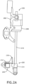
- FIGS. 2A-D illustrate a motion control device according to an embodiment of the present disclosure.
- the motion control device 200 is configured to be installed on a passenger seat having a seat back rotationally coupled to a seat pan, such as the seat frame shown in FIGS. 1A-1B .
- the seat is equipped with an actuator 202 coupled at one end to a frame member 204 located in the seat pan, and at an opposing end to a frame member 206 located in the seat back.
- the actuator 202 shown is a linear actuator generally including a stepper motor 208 and a shaft 210 in the form of a lead screw.
- the stepper motor 208 is energized to drive rotation of the lead screw.
- elongating the actuator 202 causes seat back rotation in the forward direction of the seat corresponding to seat back incline
- shortening the actuator 202 causes seat back rotation in the rearward direction of the seat corresponding to seat back recline.
- the motion control device 200 generally includes a first part 212 attachable to a frame member located in the seat pan and a second part 214 attachable to the actuator shaft 210.
- the first part 212 is attached to the transverse frame member 204 such as the tubular frame member shown.
- the first part 212 may be implemented as at least one plate 216 defining an attachment location for the first end of the actuator.
- the at least one plate 216 may further define an opening receiving the transverse frame member 204 therethrough.
- the at least one plate 216 may further include a mechanical stop 218 for stopping travel of the first end of the actuator shaft 210 in the forward direction of the seat.
- the first part 212 further includes a first clip 220 configured to interact with a second clip of the second part as discussed further below.
- the second part 214 is coupled to the actuator 202 proximate the first end of the actuator.
- the second part 214 includes an annular collar 222 positioned around the actuator shaft 210. A portion of the annular collar 222 extends radially outward toward the first part 212.
- the extension carries or forms a second clip 224 configured to interact with the first clip 220 as discussed further below.
- FIGS. 2A and 3A show the motion control device 200 during normal use of the seat (i.e., prior to a dynamic event).
- the first part 212 and the second part 214 are disengaged and do not interact.
- the first clip 220 includes a first hook 226 and the second clip 224 includes a second hook 228.
- the first and second hooks 226, 228 face each other and are ramped such that the hooks are able to pass one another to ready the motion control device 200 for engagement as discussed further below.
- the first clip 220 bends around the transverse frame member 204 for support.
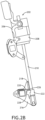
- FIG. 2B shows the motion control device 200 readied for engagement.
- the actuator 202 rotates forward carrying the second part 214 thereby causing the second hook 228 to move past the first hook 226.
- the actuator rotates forward until the shaft 210 engages the mechanical stop 218.
- the mechanical stop 218 prevents at least the first end of the shaft 210 from rotating further forward past a predetermined angle.
- the seat back and second end of the actuator may continue to rotate forward past the mechanical stop 218 thereby causing the shaft 210 to bend about the mechanical stop.
- the event threshold is an event sufficient to cause component deformation, for instance actuator shaft deformation.
- the event threshold may be a 2 g-force event, 3 g-force event, 4 g-force event, 5 g-force event... n g-force event.
- FIGS. 2C and 3B show engagement of the first and second hooks 226, 228 as the seat back rebounds following a transition from rotation in the forward direction to rotation in the rearward direction.
- the actuator 202 rotates in the rearward direction until the first and second hooks 226, 228 engage.
- Engagement of the first and second hooks 226, 228 momentarily stops rotation of the actuator 202 in the rearward direction long enough that a majority of load on the actuator 202 passes through the actuator shaft 210 and in the seat frame.
- the momentary rotational stop causes the actuator shaft 210 to bend slightly toward a forward direction of the seat (i.e., opposite the bending direction shown in FIG. 1B .
- FIGS. 2D and 3C show the disengagement of the first and second hooks 226, 228 after the dynamic event.
- the first and second hooks 226, 228 interact when the actuator shaft 210 rotates rearward to a certain point but permit the actuator shaft 210 to rotate forward. As the seat back ultimately comes to rest, the first and second hooks 226, 228 may engage to prevent further seat back rotation should the seat frame fail as a result of the dynamic event.
- the engagement position of the first and second hooks 226, 228 can be customized to determine the seat back angle following a dynamic event, considering the plastic deformation of the actuator shaft 210.
- the engagement position of the first and second clips 212, 214, length and/or angle of the mechanical stop 218, and combinations thereof may be customized to control bending in the actuator shaft 210 during a dynamic event.
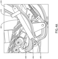
- FIGS. 4A and 4B illustrate a motion control device according to another embodiment of the present disclosure.
- the motion control device 400 generally includes a brace 402 rotatably coupled at one end to a frame member such as a seat back frame member 404.
- a detached end of the brace shown generally at 406 defines a profile matching a profile of another seat frame member, for instance a seat pan frame member 408.
- the seat pan frame member 408 is tubular and has a square cross section and the detached end 406 of the brace 402 has a matching square profile.
- a biasing member 410 for instance a tension spring, is configured to bias the detached end 406 toward the seat pan frame member 408 such that rotational movement of the seat back causes the brace 402 to drag along the seat pan frame member 408 without losing contact.
- FIG. 4A shows the brace 402 during normal use of the seat (e.g., seat movement between TTOL and reclined).
- the free end 406 is disengaged from the seat pan frame member 408.
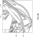
- FIG. 4B shows that as the seat back rotates forward past the TTOL position as the result of a dynamic event, the brace 402 drags along the outer surface of the seat pan frame member 408.
- FIG. 4C shows that as the seat back continues to rotate forward past TTOL the detached end 406 nears a transition point from detached to engaged.
- FIG. 4D sufficient rotational movement of the seat frame forward of TTOL clears the detached end 406 such that the detached end can move to engage the seat pan frame member 408.
- the seat back is prevented from rebounding past a certain angle thereby allowing a majority of the load to pass through the brace 402 and the actuator 202 to the seat frame.
Landscapes
- Engineering & Computer Science (AREA)
- Aviation & Aerospace Engineering (AREA)
- Transportation (AREA)
- Mechanical Engineering (AREA)
- Chairs For Special Purposes, Such As Reclining Chairs (AREA)
- Seats For Vehicles (AREA)
Applications Claiming Priority (1)
| Application Number | Priority Date | Filing Date | Title |
|---|---|---|---|
| US17/963,515 US12384280B2 (en) | 2022-10-11 | 2022-10-11 | Device for constraining actuator motion during a dynamic event |
Publications (2)
| Publication Number | Publication Date |
|---|---|
| EP4353526A2 true EP4353526A2 (de) | 2024-04-17 |
| EP4353526A3 EP4353526A3 (de) | 2024-06-26 |
Family
ID=88290923
Family Applications (1)
| Application Number | Title | Priority Date | Filing Date |
|---|---|---|---|
| EP23201921.6A Pending EP4353526A3 (de) | 2022-10-11 | 2023-10-05 | Vorrichtung zur einschränkung der aktuatorbewegung während eines dynamischen ereignisses |
Country Status (2)
| Country | Link |
|---|---|
| US (2) | US12384280B2 (de) |
| EP (1) | EP4353526A3 (de) |
Family Cites Families (11)
| Publication number | Priority date | Publication date | Assignee | Title |
|---|---|---|---|---|
| GB2269986B (en) * | 1992-07-30 | 1997-03-19 | Flight Equip & Eng | Vehicle seats |
| DE10044851C2 (de) | 2000-01-12 | 2002-10-24 | Faurecia Autositze Gmbh & Co | Kraftfahrzeugsitz |
| GB2434170B (en) | 2006-01-11 | 2008-12-10 | Saint Gobain Pipelines Plc | An access assembly |
| DE102012107036B4 (de) | 2012-08-01 | 2021-08-26 | Dr. Ing. H.C. F. Porsche Aktiengesellschaft | Kraftfahrzeugsitz |
| DE102012019810A1 (de) | 2012-10-10 | 2014-04-10 | Daimler Ag | Sitzanlage, insbesondere Fahrzeugsitz, für einen Kraftwagen |
| FR3016420B1 (fr) | 2014-01-10 | 2017-06-16 | Zodiac Actuation Systems | Actionneur et siege de cabine comprenant un tel actionneur |
| EP3347273B1 (de) * | 2015-09-11 | 2022-02-16 | Safran Seats USA LLC | Konsolidierter sitzlehnenkippmechanismus |
| DE102018119702B4 (de) | 2018-08-14 | 2020-06-04 | Adient Engineering and IP GmbH | Fahrzeugsitz, insbesondere Kraftfahrzeugsitz |
| FR3098192B1 (fr) | 2019-07-02 | 2022-09-09 | Zodiac Actuation Systems | Siège d’aéronef |
| CN114650929B (zh) | 2019-09-09 | 2025-01-07 | 安道拓美国有限责任公司 | 座椅组件 |
| US12330793B2 (en) * | 2022-09-19 | 2025-06-17 | Ami Industries, Inc. | Method for translating pins using a rotary actuator |
-
2022
- 2022-10-11 US US17/963,515 patent/US12384280B2/en active Active
-
2023
- 2023-10-05 EP EP23201921.6A patent/EP4353526A3/de active Pending
-
2025
- 2025-07-30 US US19/285,387 patent/US20250353413A1/en active Pending
Also Published As
| Publication number | Publication date |
|---|---|
| US20250353413A1 (en) | 2025-11-20 |
| EP4353526A3 (de) | 2024-06-26 |
| US20240116415A1 (en) | 2024-04-11 |
| US12384280B2 (en) | 2025-08-12 |
Similar Documents
| Publication | Publication Date | Title |
|---|---|---|
| US20080252112A1 (en) | Active material head restraint assembly | |
| US10773805B2 (en) | Consolidated seat back breakover mechanism | |
| CN111071117B (zh) | 车辆用座椅 | |
| EP4353526A2 (de) | Vorrichtung zur einschränkung der aktuatorbewegung während eines dynamischen ereignisses | |
| WO2017022492A1 (ja) | 乗物用シート | |
| US5738475A (en) | Adjustable expansion rivet | |
| EP3010766B1 (de) | Selbstausrichtend sicherheitsgurt | |
| WO2006093644A1 (en) | Energy absorption apparatus | |
| US9586503B1 (en) | Vehicle seat and torsion bar | |
| EP4339103B1 (de) | Verfahren zum verschieben von stiften mittels eines drehaktuators | |
| US11535138B2 (en) | Device for influencing a backward movement of a seat and seat | |
| EP4212434B1 (de) | Passagierpositionierungsvorrichtungen für flugzeugsitze zur einhaltung der regulierung | |
| WO2009091300A1 (en) | A seat comprising an anti- whiplash mechanism and a method for fitting such a mechanism to a seat | |
| US20240158086A1 (en) | System including seat pan assembly | |
| CN110789414B (zh) | 车辆座椅和组装方法 | |
| JP2013545660A (ja) | 航空機の座席用シートベルト取付装置 | |
| US20230302980A1 (en) | Cable sleeve for a foldable headrest | |
| EP4353593B1 (de) | Flugzeugsitz mit verschachteltem energiedämpfungsführungssystem | |
| CN114889550A (zh) | 一种人体坐姿综合约束装置 | |
| EP1859706A1 (de) | Liegesitz für kraftfahrzeuge | |
| US10252648B2 (en) | Inertia driven rotatable upper seat portion for rear passenger head clearance | |
| EP3604030B1 (de) | Lineare trägheitsverriegelung | |
| US20170240070A1 (en) | Release lever counterweight | |
| WO2022197675A3 (en) | Seating arrangement | |
| US20190299922A1 (en) | Adaptive belt for impact |
Legal Events
| Date | Code | Title | Description |
|---|---|---|---|
| PUAI | Public reference made under article 153(3) epc to a published international application that has entered the european phase |
Free format text: ORIGINAL CODE: 0009012 |
|
| STAA | Information on the status of an ep patent application or granted ep patent |
Free format text: STATUS: THE APPLICATION HAS BEEN PUBLISHED |
|
| AK | Designated contracting states |
Kind code of ref document: A2 Designated state(s): AL AT BE BG CH CY CZ DE DK EE ES FI FR GB GR HR HU IE IS IT LI LT LU LV MC ME MK MT NL NO PL PT RO RS SE SI SK SM TR |
|
| PUAL | Search report despatched |
Free format text: ORIGINAL CODE: 0009013 |
|
| RIC1 | Information provided on ipc code assigned before grant |
Ipc: B60N 2/433 20060101ALI20240508BHEP Ipc: B60N 2/23 20060101ALI20240508BHEP Ipc: B60N 2/02 20060101AFI20240508BHEP |
|
| AK | Designated contracting states |
Kind code of ref document: A3 Designated state(s): AL AT BE BG CH CY CZ DE DK EE ES FI FR GB GR HR HU IE IS IT LI LT LU LV MC ME MK MT NL NO PL PT RO RS SE SI SK SM TR |
|
| RIC1 | Information provided on ipc code assigned before grant |
Ipc: B60N 2/433 20060101ALI20240522BHEP Ipc: B60N 2/23 20060101ALI20240522BHEP Ipc: B60N 2/02 20060101AFI20240522BHEP |
|
| STAA | Information on the status of an ep patent application or granted ep patent |
Free format text: STATUS: REQUEST FOR EXAMINATION WAS MADE |
|
| 17P | Request for examination filed |
Effective date: 20241219 |