EP4353502A1 - Vehicular refrigeration cycle unit - Google Patents
Vehicular refrigeration cycle unit Download PDFInfo
- Publication number
- EP4353502A1 EP4353502A1 EP22928832.9A EP22928832A EP4353502A1 EP 4353502 A1 EP4353502 A1 EP 4353502A1 EP 22928832 A EP22928832 A EP 22928832A EP 4353502 A1 EP4353502 A1 EP 4353502A1
- Authority
- EP
- European Patent Office
- Prior art keywords
- flow passage
- secondary refrigerant
- refrigeration cycle
- flow
- unit
- Prior art date
- Legal status (The legal status is an assumption and is not a legal conclusion. Google has not performed a legal analysis and makes no representation as to the accuracy of the status listed.)
- Withdrawn
Links
Images





Classifications
-
- B—PERFORMING OPERATIONS; TRANSPORTING
- B60—VEHICLES IN GENERAL
- B60H—ARRANGEMENTS OF HEATING, COOLING, VENTILATING OR OTHER AIR-TREATING DEVICES SPECIALLY ADAPTED FOR PASSENGER OR GOODS SPACES OF VEHICLES
- B60H1/00—Heating, cooling or ventilating devices
- B60H1/00642—Control systems or circuits; Control members or indication devices for heating, cooling or ventilating devices
- B60H1/00814—Control systems or circuits characterised by their output, for controlling particular components of the heating, cooling or ventilating installation
- B60H1/00878—Control systems or circuits characterised by their output, for controlling particular components of the heating, cooling or ventilating installation the components being temperature regulating devices
- B60H1/00885—Controlling the flow of heating or cooling liquid, e.g. valves or pumps
-
- B—PERFORMING OPERATIONS; TRANSPORTING
- B60—VEHICLES IN GENERAL
- B60H—ARRANGEMENTS OF HEATING, COOLING, VENTILATING OR OTHER AIR-TREATING DEVICES SPECIALLY ADAPTED FOR PASSENGER OR GOODS SPACES OF VEHICLES
- B60H1/00—Heating, cooling or ventilating devices
- B60H1/32—Cooling devices
- B60H1/3204—Cooling devices using compression
- B60H1/3228—Cooling devices using compression characterised by refrigerant circuit configurations
- B60H1/32284—Cooling devices using compression characterised by refrigerant circuit configurations comprising two or more secondary circuits, e.g. at evaporator and condenser side
-
- B—PERFORMING OPERATIONS; TRANSPORTING
- B60—VEHICLES IN GENERAL
- B60H—ARRANGEMENTS OF HEATING, COOLING, VENTILATING OR OTHER AIR-TREATING DEVICES SPECIALLY ADAPTED FOR PASSENGER OR GOODS SPACES OF VEHICLES
- B60H1/00—Heating, cooling or ventilating devices
- B60H1/00642—Control systems or circuits; Control members or indication devices for heating, cooling or ventilating devices
- B60H1/00814—Control systems or circuits characterised by their output, for controlling particular components of the heating, cooling or ventilating installation
- B60H1/00878—Control systems or circuits characterised by their output, for controlling particular components of the heating, cooling or ventilating installation the components being temperature regulating devices
- B60H1/00899—Controlling the flow of liquid in a heat pump system
-
- B—PERFORMING OPERATIONS; TRANSPORTING
- B60—VEHICLES IN GENERAL
- B60H—ARRANGEMENTS OF HEATING, COOLING, VENTILATING OR OTHER AIR-TREATING DEVICES SPECIALLY ADAPTED FOR PASSENGER OR GOODS SPACES OF VEHICLES
- B60H1/00—Heating, cooling or ventilating devices
- B60H1/32—Cooling devices
- B60H2001/3236—Cooling devices information from a variable is obtained
- B60H2001/3255—Cooling devices information from a variable is obtained related to temperature
- B60H2001/3257—Cooling devices information from a variable is obtained related to temperature of the refrigerant at a compressing unit
-
- B—PERFORMING OPERATIONS; TRANSPORTING
- B60—VEHICLES IN GENERAL
- B60H—ARRANGEMENTS OF HEATING, COOLING, VENTILATING OR OTHER AIR-TREATING DEVICES SPECIALLY ADAPTED FOR PASSENGER OR GOODS SPACES OF VEHICLES
- B60H1/00—Heating, cooling or ventilating devices
- B60H1/32—Cooling devices
- B60H2001/3269—Cooling devices output of a control signal
- B60H2001/3276—Cooling devices output of a control signal related to a condensing unit
-
- B—PERFORMING OPERATIONS; TRANSPORTING
- B60—VEHICLES IN GENERAL
- B60H—ARRANGEMENTS OF HEATING, COOLING, VENTILATING OR OTHER AIR-TREATING DEVICES SPECIALLY ADAPTED FOR PASSENGER OR GOODS SPACES OF VEHICLES
- B60H1/00—Heating, cooling or ventilating devices
- B60H1/32—Cooling devices
- B60H2001/3269—Cooling devices output of a control signal
- B60H2001/328—Cooling devices output of a control signal related to an evaporating unit
Definitions
- a secondary refrigerant type heat pump system is used as a heat source for an air conditioner (heating).
- the secondary refrigerant type heat pump system mainly includes a vehicle exterior heat exchanger which is connected to an evaporator of a refrigeration cycle allowing a primary refrigerant to flow therethrough and through which a secondary refrigerant flows and a vehicle interior heat exchanger which is connected to a condenser side of the refrigeration cycle and through which the secondary refrigerant flows.
- the heat of the secondary refrigerant heated by the exterior air is transferred to the vehicle interior heat exchanger via the refrigeration cycle. Accordingly, it is possible to heat the interior air.
- a device according to Patent Document 1 below adopts a configuration in which a secondary refrigerant flowing through a vehicle interior heat exchanger (that is, a condenser side) flows while being mixed at an evaporator side of a refrigeration cycle. Accordingly, it is said that the pressure of a primary refrigerant heading to a compressor via the evaporator can be increased.
- Patent Document 1 Japanese Patent No. 6083304
- the present disclosure has been made to solve the above-described problems and an object thereof is to provide a vehicular refrigeration cycle unit capable of more precisely adjusting a temperature of a secondary refrigerant.
- a vehicular refrigeration cycle unit which is installed between a vehicle exterior heat exchanger and a vehicle interior heat exchanger and exchanging heat between secondary refrigerants respectively flowing through the vehicle exterior heat exchanger and the vehicle interior heat exchanger
- the vehicular refrigeration cycle unit including: a refrigeration cycle including a compressor, a condenser, an expansion valve, and an evaporator through which a primary refrigerant sequentially flows; an exterior flow passage through which the secondary refrigerant is circulated between the evaporator and the vehicle exterior heat exchanger; an interior flow passage through which the secondary refrigerant is circulated between the condenser and the vehicle interior heat exchanger; a pair of flow passage switching valves connecting the exterior flow passage and the interior flow passage to allow to switch a flow state of the second refrigerant between the exterior flow passage and the interior flow passage; a first bypass flow passage which is aside the exterior flow passage with bypassing the evaporator; and a first flow rate
- a vehicular refrigeration cycle unit capable of more precisely adjusting a temperature of a secondary refrigerant.
- FIGS. 1 to 5 a vehicular refrigeration cycle unit 1 according to a first embodiment of the present disclosure will be described with reference to FIGS. 1 to 5 .
- the vehicular refrigeration cycle unit 1 is air conditioning equipment installed in a transportation vehicle such as an electric vehicle that does not have an engine as a heat source during heating.
- the vehicular refrigeration cycle unit 1 is mounted to be interposed between a vehicle exterior heat exchanger 10 disposed on a vehicle exterior side and a vehicle interior heat exchanger 20 disposed on a vehicle interior side.
- the refrigerant (coolant) flowing through the vehicle exterior heat exchanger 10 and the vehicle interior heat exchanger 20 is hereinafter referred to as a "secondary refrigerant" and the refrigerant flowing through a refrigeration cycle 30 (described later) is referred to as a "primary refrigerant".
- the vehicular refrigeration cycle unit 1 includes the refrigeration cycle 30 through which the primary refrigerant flows, an exterior flow passage 40 which is disposed on an exterior side, an interior flow passage 50 which is disposed on an interior side, a pair of flow passage switching valves 60 which switches the mutual flow state of the exterior flow passage 40 and the interior flow passage 50, a first bypass flow passage 41 which is alongside the exterior flow passage 40, a first flow rate adjustment unit 42, a second bypass flow passage 51 which is alongside the interior flow passage 50, a second flow rate adjustment unit 52, a first pump 43 which is provided on the exterior flow passage 40, a second pump 53 which is provided on the interior flow passage 50, an exterior connection flow passage 44, a first switching valve 45, an interior connection flow passage 54, a second switching valve 55, a measurement unit 46, and a control unit 90.
- valves of the vehicular refrigeration cycle unit 1 are painted black, they are in a closed state and if these valves are painted white, they are in an open state. Further, the directions in which various refrigerants flow are indicated by arrows drawn along the circuits.
- the refrigeration cycle 30 is composed of a plurality of devices that realize a thermodynamic cycle.
- the refrigeration cycle 30 is a refrigerant circuit that allows the primary refrigerant as a heat medium to sequentially flow and circulate in a plurality of devices while repeatedly compressing, expanding, evaporating, and condensing the primary refrigerant in order to exchange heat between the primary refrigerant and the secondary refrigerant.
- the refrigeration cycle 30 includes a refrigeration cycle line 31 and a compressor 32, a condenser 33, an expansion valve 34, and an evaporator 35 sequentially arranged on this refrigeration cycle line 31.
- the evaporator 35 is a plate heat exchanger that evaporates (vaporizes) the primary refrigerant by exchanging heat between the primary refrigerant sequentially flows through the refrigeration cycle 30 and the secondary refrigerant introduced from the outside of the refrigeration cycle 30.
- the primary refrigerant inside the evaporator 35 absorbs heat from the secondary refrigerant and simultaneously cools the secondary refrigerant.
- the compressor 32 is a device that absorbs heat and compresses the vaporized primary refrigerant by passing through the evaporator 35.
- the pressure of the primary refrigerant introduced into the compressor 32 is increased to a predetermined pressure higher than before compression by the compression operation of the compressor 32. Accordingly, the temperature of the primary refrigerant becomes higher than before compression.
- the condenser 33 is a plate heat exchanger that condenses (liquefies) the primary refrigerant by exchanging heat between the primary refrigerant passing through the compressor 32 to have a temperature and a pressure higher than before compression and the secondary refrigerant introduced from the outside of the refrigeration cycle 30.
- the primary refrigerant inside the condenser 33 is cooled by the secondary refrigerant and simultaneously increases the temperature of the secondary refrigerant.
- the primary refrigerant in a gas state introduced into the condenser 33 is cooled by the secondary refrigerant, passes through a two-phase state of a gas-liquid mixture, and then transitions to a liquid state.
- the expansion valve 34 is a device that receives the primary refrigerant changing into a liquid state via the condenser 33 and adiabatically expands the primary refrigerant.
- the pressure of the primary refrigerant introduced to the expansion valve 34 is decreased to a predetermined pressure lower than before expansion due to the expansion action of the expansion valve 34. Accordingly, the temperature of the primary refrigerant becomes lower than before expansion.
- the exterior flow passage 40 is a flow passage that connects the evaporator 35 in the refrigeration cycle 30 and the vehicle exterior heat exchanger 10 in an annular shape.
- the secondary refrigerant flows through the exterior flow passage 40.
- the first pump 43, the first switching valve 45, and the exterior connection flow passage 44 are provided on the exterior flow passage 40.
- the first pump 43 pressure-feeds the secondary refrigerant flowing through the exterior flow passage 40.
- the first switching valve 45 is a three-way valve that can switch the flow state between three flow passages.
- the exterior connection flow passage 44 extends with bypassing the vehicle exterior heat exchanger 10 from the first switching valve 45 as a start point.
- the first switching valve 45 is electrically connected to the control unit 90 to be described later and the flow state of the secondary refrigerant is switched by the electric signal sent from the control unit 90.
- the first bypass flow passage 41 is provided alongside the exterior flow passage 40 and extends with bypassing the evaporator 35.
- a flow rate adjustment valve 70 is provided at one end of the first bypass flow passage 41 as the first flow rate adjustment unit 42.
- the flow rate adjustment valve 70 is a three-way valve. That is, the flow rate adjustment valve 70 can distribute the secondary refrigerant flowing from one flow passage into two flow passages and change the ratio of the flow rate of the secondary refrigerant between these two flow passages.
- the first flow rate adjustment unit 42 changes the ratio of the flow rate of the secondary refrigerant flowing into the evaporator 35 via the exterior flow passage 40 and the flow rate of the secondary refrigerant flowing into the first bypass flow passage 41.
- the ratio of the flow rate is realized by changing the internal structure of the valve of the flow rate adjustment valve 70.
- the flow rate adjustment valve 70 is electrically connected to the control unit 90 (to be described later). The internal structure of the valve is controlled based on the electric signal sent from the control unit 90.
- the interior flow passage 50 is a flow passage that connects the condenser 33 in the refrigeration cycle 30 and the vehicle interior heat exchanger 20 in an annular shape.
- the secondary refrigerant flows through the interior flow passage 50.
- the second pump 53, the second switching valve 55, and the interior connection flow passage 54 are provided on this interior flow passage 50.
- the second pump 53 pressure-feeds the secondary refrigerant flowing through the interior flow passage 50.
- the second switching valve 55 is a three-way valve similarly to the first switching valve 45.
- the second switching valve 55 is electrically connected to the control unit 90 to be described later and the flow state of the secondary refrigerant is switched by the electric signal sent from the control unit 90.
- the interior connection flow passage 54 extends with bypassing the vehicle interior heat exchanger 20 from the second switching valve 55 as a start point.
- the second bypass flow passage 51 is provided alongside the interior flow passage 50 and extends with bypassing the condenser 33.
- the flow rate adjustment valve 70 is provided at one end of the second bypass flow passage 51 as the second flow rate adjustment unit 52.
- the flow rate adjustment valve 70 is a three-way valve. That is, the flow rate adjustment valve 70 can distribute the secondary refrigerant flowing from one flow passage into two flow passages and change the ratio of the flow rate of the secondary refrigerant between these two flow passages.
- the second flow rate adjustment unit 52 changes the ratio of the flow rate of the secondary refrigerant flowing into the condenser 33 via the interior flow passage 50 and the flow rate of the secondary refrigerant flowing into the second bypass flow passage 51.
- the ratio of the flow rate is controlled based on the electric signal sent from the control unit 90 similarly to the first flow rate adjustment unit 42.
- the exterior flow passage 40 and the interior flow passage 50 are connected by the pair of flow passage switching valves 60 (a first flow passage switching valve 61 and a second flow passage switching valve 62). More specifically, the first flow passage switching valve 61 is provided between the vehicle exterior heat exchanger 10 in the exterior flow passage 40 and the first flow rate adjustment unit 42 and between the vehicle interior heat exchanger 20 in the interior flow passage 50 and the second flow rate adjustment unit 52. Further, the second flow passage switching valve 62 is provided between the first switching valve 45 in the exterior flow passage 40 and the first pump 43 and between the second switching valve 55 in the interior flow passage 50 and the second pump 53.
- the flow state of the secondary refrigerant between the exterior flow passage 40 and the interior flow passage 50 is mutually switched by providing the first flow passage switching valve 61 and the second flow passage switching valve 62.
- the first flow passage switching valve 61 and the second flow passage switching valve 62 are electrically connected to the control unit 90 (to be described later) and the flow state is switched based on the electric signal sent from the control unit 90.
- the measurement unit 46 measures a physical quantity related to the pressure of the primary refrigerant on the downstream side of the evaporator 35 in the refrigeration cycle line 31. Additionally, the physical quantity mentioned herein may be the pressure of the primary refrigerant itself or the temperature of the primary refrigerant. That is, the measurement unit 46 is a pressure gauge or a thermometer.
- the physical quantity measured by the measurement unit 46 is sent to the control unit 90 as the electric signal.
- the control unit 90 adjusts the flow state of the first flow rate adjustment unit 42 based on the measurement result of the measurement unit 46.
- step S100 it is determined whether or not the control using the control unit 90 is in an on state. In the case of an off state (step S100: No), the process ends. In the case of an on state (step S 100: Yes), the control unit 90 acquires a physical quantity p related to the pressure of the primary refrigerant from the measurement unit 46 in step S 101 below.
- step S 102 the control unit 90 determines the magnitude relationship between the physical quantity p and the threshold value. When it is determined that the physical quantity p is larger than the threshold value (step S 102: Yes), the process proceeds to step S 103.
- step S103 the control unit 90 sends an electric signal to the first flow rate adjustment unit 42 (the flow rate adjustment valve 70) so that the flow rate of the secondary refrigerant flowing into the evaporator 35 changes in a decrease direction.
- step S104 the control unit 90 sends an electric signal to the first flow rate adjustment unit 42 (the flow rate adjustment valve 70) so that the flow rate of the secondary refrigerant flowing into the evaporator 35 changes in an increase direction. In this way, the flow state of the first flow rate adjustment unit 42 is controlled based on the physical quantity of the primary refrigerant flowing out from the evaporator 35.
- the operation mode is appropriately selected between a heater mode that is used when the outside air temperature is particularly low (for example, about -20°C) and a heat pump mode that is used when the outside air temperature is higher than that of the heater mode.
- the flow state of the first flow passage switching valve 61 and the second flow passage switching valve 62 is switched so that the exterior flow passage 40 and the interior flow passage 50 are independent of each other in this mode. Further, the exterior connection flow passage 44 and the interior connection flow passage 54 are respectively closed by the first switching valve 45 and the second switching valve 55. The first bypass flow passage 41 and the second bypass flow passage 51 are respectively closed by the first flow rate adjustment unit 42 and the second flow rate adjustment unit 52.
- the secondary refrigerant flows through the path indicated by the arrow in FIG. 2 .
- the secondary refrigerant passing through the second flow passage switching valve 62 via the first pump 43 flows into the vehicle exterior heat exchanger 10 and then flows toward the first flow passage switching valve 61.
- the secondary refrigerant flows into the evaporator 35 via the first flow rate adjustment unit 42.
- the secondary refrigerant exchanging heat with the primary refrigerant of the refrigeration cycle 30 in the evaporator 35 is in a low temperature state.
- the secondary refrigerant flowing out from the evaporator 35 flows into the first pump 43 again. Such a flow occurs continuously.
- the secondary refrigerant passing through the second flow passage switching valve 62 via the second pump 53 exchanges heat with interior air in the vehicle interior heat exchanger 20. Accordingly, the secondary refrigerant becomes a low temperature state and flows toward the first flow passage switching valve 61. Then, the secondary refrigerant flows to the condenser 33 via the second flow rate adjustment unit 52. The secondary refrigerant exchanging heat with the primary refrigerant in the condenser 33 becomes a high temperature state. The secondary refrigerant flowing out from the condenser 33 flows into the second pump 53 again. Such a flow occurs continuously.
- heat is exchanged between the primary refrigerant and the secondary refrigerant. Specifically, heat is exchanged between the relatively high-temperature outside air and the relatively low-temperature secondary refrigerant in the vehicle exterior heat exchanger 10. The heat of the secondary refrigerant heated by heat exchange with the outside air is transferred to the secondary refrigerant in the interior flow passage 50 via the refrigeration cycle 30. The secondary refrigerant in the interior flow passage 50 exchanges heat with the interior air in the vehicle interior heat exchanger 20. Accordingly, the interior temperature increases.
- the open and close states of various valves and the flow state of the secondary refrigerant are as shown in FIG. 3 during a stationary operation of the heater mode.
- the exterior connection flow passage 44 is opened by the first switching valve 45 and the secondary refrigerant flows with bypassing the vehicle exterior heat exchanger 10.
- the flow state is switched so that the secondary refrigerant flowing through the interior flow passage 50 flows into the exterior flow passage 40 and the secondary refrigerant flowing through the exterior flow passage 40 flows into the interior flow passage 50.
- the second flow passage switching valve 62 the flow state is switched so that the secondary refrigerant discharged from the first pump 43 flows through the exterior flow passage 40 and the secondary refrigerant discharged from the second pump 53 flows through the interior flow passage 50.
- the secondary refrigerant which flows from the interior flow passage 50 into the exterior flow passage 40 via the first flow passage switching valve 61 is distributed to the side of the evaporator 35 and the side of the first bypass flow passage 41.
- the ratio of the flow rate of the secondary refrigerant flowing through the evaporator 35 and the flow rate of the secondary refrigerant flowing through the first bypass flow passage 41 is controlled by the above-described control flow.
- the secondary refrigerant which flows from the exterior flow passage 40 into the interior flow passage 50 via the first flow passage switching valve 61 is controlled to flow not to the second bypass flow passage 51 but to the condenser 33.
- the secondary refrigerant flows through the path indicated by the arrow in FIG. 3 .
- the secondary refrigerant discharged from the first pump 43 flows toward the first switching valve 45 via the second flow passage switching valve 62 on the side of the evaporator 35.
- the secondary refrigerant flowing into the exterior connection flow passage 44 via the first switching valve 45 flows into the interior flow passage 50 via the first flow passage switching valve 61.
- the secondary refrigerant flowing into the interior flow passage 50 flows into the condenser 33 via the second flow rate adjustment unit 52.
- the secondary refrigerant that exchanges heat with the primary refrigerant in the condenser 33 becomes a high temperature state and flows into the second pump 53.
- the secondary refrigerant discharged from the second pump 53 flows through the interior flow passage 50 again via the second flow passage switching valve 62 and heads toward the vehicle interior heat exchanger 20.
- the secondary refrigerant that exchanges heat with the interior air in the vehicle interior heat exchanger 20 becomes a low temperature state and heads toward the first flow passage switching valve 61 through the interior flow passage 50.
- the secondary refrigerant flowing into the exterior flow passage 40 via the first flow passage switching valve 61 is distributed to the flow toward the evaporator 35 and the flow toward the first bypass flow passage 41 via the first flow rate adjustment unit 42.
- the evaporator 35 heat is exchanged between the secondary refrigerant and the primary refrigerant. Accordingly, the secondary refrigerant becomes a low-temperature state. These two flows merge on the downstream side of the evaporator 35 and then heads toward the first pump 43. The above-described flow of the secondary refrigerant continuously occurs.
- the relatively high-temperature secondary refrigerant flows from the interior flow passage 50 into the evaporator 35. Accordingly, the temperature of the primary refrigerant in the refrigeration cycle 30 that exchanges heat with the secondary refrigerant increases. As the temperature increases, the pressure and density of the primary refrigerant also increase. Since the density of the primary refrigerant increases, the load of the compressor 32 also increases. In other words, the work amount of the compressor 32 increases. As a result, the amount of heat generated in accordance with the operation of the compressor 32 increases. This increased amount of heat is transferred to the primary refrigerant and then transferred to the secondary refrigerant flowing through the interior flow passage 50 in the condenser 33 on the downstream side of the compressor 32. Accordingly, the temperature of the secondary refrigerant increases. The heated secondary refrigerant exchanges heat with the interior air in the vehicle interior heat exchanger 20. As a result, the interior temperature increases (heating occurs).
- the compression ratio of the compressor 32 decreases. That is, the Mollier diagram in this case becomes the graph indicated by the solid line in FIG. 4 . Additionally, the dashed line in FIG. 4 indicates the Mollier diagram in the heat pump mode.
- the pressure shown on the vertical axis increases compared to the heat pump mode and the difference between the upper limit and the lower limit decreases compared to the heat pump mode. Accordingly, it is possible to operate the compressor 32 at a pressure close to the upper limit value of the discharge pressure of the compressor 32. As a result, the load of the compressor 32 further increases and more heat can be generated by the compressor 32.
- the heat generated by the compressor 32 is transferred to the primary refrigerant and then transferred to the secondary refrigerant flowing through the interior flow passage 50 in the condenser 33. Accordingly, the temperature of the secondary refrigerant increases.
- the heated secondary refrigerant exchanges heat with the interior air in the vehicle interior heat exchanger 20. As a result, it is possible to further improve the heating performance of the vehicular refrigeration cycle unit 1.
- the temperature of the primary refrigerant flowing through the evaporator 35 in the refrigeration cycle 30 by adjusting the flow rate of the secondary refrigerant flowing into the evaporator 35 using the first flow rate adjustment unit 42. Accordingly, since the pressure and density of the primary refrigerant change to desired values, it is possible to precisely adjust the load (work amount) of the compressor 32. That is, it is possible to precisely control the amount of heat transferred from the compressor 32 to the primary refrigerant. As a result, it is possible to precisely control the temperature of the secondary refrigerant during the heating operation.
- the control unit 90 appropriately adjusts the flow state of the first flow rate adjustment unit 42 based on the physical quantity related to the pressure of the secondary refrigerant on the downstream side of the evaporator 35. Accordingly, the ratio of the flow rates of the secondary refrigerants flowing into the evaporator 35 and the first bypass flow passage 41 changes autonomously. Thus, it is possible to more precisely control the amount of heat transferred from the compressor 32 to the primary refrigerant.
- the second flow rate adjustment unit 52 is controlled so that the secondary refrigerant flows not to the condenser 33 but to the second bypass flow passage 51 contrary to the above description. Accordingly, the pressure of the primary refrigerant flowing through the condenser 33 in the refrigeration cycle 30 increases. Then, when shifting to the above-described stationary operation, the second flow rate adjustment unit 52 is controlled so that the flow rate of the secondary refrigerant flowing into the condenser 33 gradually increases.
- the pressure and temperature of the primary refrigerant flowing through the condenser 33 in the refrigeration cycle 30 it is possible to control the pressure and temperature of the primary refrigerant flowing through the condenser 33 in the refrigeration cycle 30.
- the amount of the secondary refrigerant flowing through the condenser 33 is minimized and the main flow is allowed to flow through the second bypass flow passage 51. Accordingly, the flow amount of the low-temperature secondary refrigerant flowing from the exterior flow passage 40 toward the interior flow passage 50 to flow into the condenser 33 is reduced.
- the pressure and temperature of the primary refrigerant in the refrigeration cycle 30 increase quickly.
- the temperature of the secondary refrigerant exchanging heat with the primary refrigerant also increases quickly, it is possible to quickly heat the temperature of the interior air during the heating operation.
- the flow rate adjustment valve 70 is used as the first flow rate adjustment unit 42 and the second flow rate adjustment unit 52, it is possible to suppress an increase in the number of parts and avoid complicating the configuration. As a result, it is possible to more easily perform manufacturing and maintenance of the vehicular refrigeration cycle unit 1 at a lower cost.
- the first embodiment of the present disclosure has been described. Additionally, various changes and modifications can be made to each of the above configurations without departing from the gist of the present disclosure.
- the secondary refrigerant does not flow into the vehicle exterior heat exchanger 10 at all by switching the first switching valve 45 in the heater mode.
- the first switching valve 45 may be controlled so that a small flow rate of the secondary refrigerant flows through the vehicle exterior heat exchanger 10 depending on the outside air temperature or operation state.
- a second embodiment of the present disclosure will be described with reference to FIG. 6 . Additionally, the same configurations as those of the first embodiment are denoted by the same reference numerals and detailed descriptions are omitted.
- the configurations of a first flow rate adjustment unit 142 and a second flow rate adjustment unit 152 are different from those of the first embodiment.
- the first flow rate adjustment unit 142 and the second flow rate adjustment unit 152 are configured by on-off valves 80 and 81 instead of the flow rate adjustment valve 70.
- These on-off valves 80 and 81 are respectively provided on the first bypass flow passage 41 and the second bypass flow passage 51.
- the on-off valves 80 and 81 are electrically connected to the above-described control unit 90 and the opening and closing state is switched by the electric signal sent from the control unit 90.
- the confluence of the first bypass flow passage 41 and the exterior flow passage 40 is located on the downstream side of the first pump 43.
- the confluence of the second bypass flow passage 51 and the interior flow passage 50 is located on the downstream side of the second pump 53.
- the first pump 43 and the second pump 53 have variable rotation speeds and can change the discharge flow rate.
- the first pump 43 and the second pump 53 are electrically connected to the control unit 90 and the discharge flow rate is controlled by the electric signal sent from a drive unit 94 of the control unit 90.
- the first pump 43 constitutes part of the first flow rate adjustment unit 142 and the second pump 53 constitutes part of the second flow rate adjustment unit 152.
- FIG. 6 shows a state in which the vehicular refrigeration cycle unit 101 is operated in the heater mode.
- the on-off valve 80 which is part of the first flow rate adjustment unit 142 is kept open.
- the discharge flow rate of the first pump 43 which is a part of the first flow rate adjustment unit 142 in this state, the ratio of the flow rate of the secondary refrigerant flowing into the evaporator 35 and the flow rate of the secondary refrigerant flowing into the first bypass flow passage 41 is adjusted.
- the on-off valves 80 and 81 are used instead of the flow rate adjustment valve 70, it is possible to reduce the costs required for manufacturing and maintenance of the device. Further, since the flow rate of the secondary refrigerant is controlled by controlling the discharge flow rates of the first pump 43 and the second pump 53, it is possible to more precisely adjust the temperature of the secondary refrigerant compared to a condition where the same flow rate control is performed using the flow rate adjustment valve 70.
- FIGS. 7 to 10 a third embodiment of the present disclosure will be described with reference to FIGS. 7 to 10 . Additionally, the same configurations as those of the above-described embodiments are denoted by the same reference numerals and detailed descriptions are omitted.
- a vehicular refrigeration cycle unit 201 further includes a first temperature measurement unit 47, a second temperature measurement unit 48, a third temperature measurement unit 49, and a pressure measurement unit 83 in addition to each configuration described in the second embodiment.
- the first temperature measurement unit 47 measures the temperature of the secondary refrigerant on the downstream side of the confluence between the first bypass flow passage 41 and the exterior flow passage 40.
- the second temperature measurement unit 48 measures the temperature of the primary refrigerant at the inlet of the compressor 32.
- the third temperature measurement unit 49 measures the temperature of the secondary refrigerant on the downstream side of the confluence between the interior flow passage 50 and the second bypass flow passage 51.
- the first temperature measurement unit 47, the second temperature measurement unit 48, and the third temperature measurement unit 49 are temperature sensors or thermometers. Additionally, the first temperature measurement unit 47, the second temperature measurement unit 48, and the third temperature measurement unit 49 are not shown in FIG. 7 .
- the pressure measurement unit 83 measures the pressure (high pressure side pressure) of the primary refrigerant on the downstream side of the compressor 32.
- the pressure measurement unit 83 is a pressure sensor or pressure gauge. Further, in this embodiment, a blower 21 provided alongside the vehicle interior heat exchanger 20 is shown.
- the flow rate of the secondary refrigerant flowing into the condenser 33 is decreased as shown in FIG. 7 .
- step S21 it is determined whether or not the pressure of the primary refrigerant measured by the pressure measurement unit 83 is higher than the threshold value.
- step S21: Yes it is determined that the pressure is higher than the threshold value (step S21: Yes)
- step S21: No it is determined whether or not the pressure of the primary refrigerant measured by the pressure measurement unit 83 is lower than the threshold value in step S23.
- step S23 it is determined whether or not the pressure of the primary refrigerant measured by the pressure measurement unit 83 is lower than the threshold value in step S23.
- step S23 the condenser flow rate is decreased in step S24.
- the temperature of the primary refrigerant is increased for a temperature difference with the secondary refrigerant to radiate heat from the primary refrigerant in the condenser 33.
- the pressure and temperature of the primary refrigerant increase quickly. Accordingly, it is possible to quickly heat the interior air.
- the control unit 90 switches the flow state of the first switching valve 45 so that the secondary refrigerant flows into the exterior connection flow passage 44.
- the control unit switches the flow state of the first switching valve 45 so that the secondary refrigerant flows into the vehicle exterior heat exchanger 10.
- step S51 it is determined whether or not the temperature T1 of the secondary refrigerant measured by the first temperature measurement unit 47 is lower than the outside air temperature.
- step S51 it is determined whether or not the temperature T1 of the secondary refrigerant measured by the first temperature measurement unit 47 is lower than the outside air temperature.
- the flow state of the first switching valve 45 is switched so that the secondary refrigerant flows into the vehicle exterior heat exchanger 10 in step S52.
- step S51 is No
- the flow state of the first switching valve 45 is switched so that the secondary refrigerant flows into the exterior connection flow passage 44 with bypassing the vehicle exterior heat exchanger 10 in step S53.
- the secondary refrigerant bypasses the vehicle exterior heat exchanger 10 using the exterior connection flow passage 44 when the temperature of the secondary refrigerant is higher than the outside air temperature. Accordingly, it is possible to prevent a decrease in the heat amount of the secondary refrigerant and to prevent a decrease in the pressure (low pressure side pressure) of the primary medium on the side of the evaporator 35. Thus, it is possible to quickly obtain a heating effect when starting the vehicular refrigeration cycle unit 1.
- control unit 90 increases the flow rate of the secondary refrigerant flowing into the evaporator in a condition where the temperature T2 of the primary refrigerant at the inlet of the compressor 32 measured by the second temperature measurement unit 48 is lower than a predetermined first threshold value when starting the vehicular refrigeration cycle unit 1.
- step S31 it is determined whether or not the temperature of the primary refrigerant measured by the second temperature measurement unit 48 is higher than the first threshold value.
- step S31: Yes it is determined that the temperature is higher than the first threshold value (step S31: Yes)
- step S31: No it is determined whether or not the temperature of the primary refrigerant measured by the second temperature measurement unit 48 is lower than the threshold value in step S33.
- step S33 it is determined whether or not the temperature of the primary refrigerant measured by the second temperature measurement unit 48 is lower than the threshold value in step S33.
- the pressure and temperature of the primary refrigerant flowing through the evaporator 35 by adjusting the amount of the secondary refrigerant flowing into the evaporator 35.
- the pressure and temperature of the primary refrigerant increase quickly by allowing the secondary refrigerant to flow through the evaporator 35 at startup. Accordingly, it is possible to quickly heat the interior air.
- the flow rate of the secondary refrigerant flowing out from the condenser 33 and flowing through the evaporator 35 increases, the amount of heat absorbed from the secondary refrigerant to the primary refrigerant increases and the low pressure side pressure of the primary refrigerant increases.
- the low pressure side pressure of the primary refrigerant increases, the temperature of the primary refrigerant at the inlet of the compressor 32 increases and hence the refrigerant density of the primary refrigerant at the inlet of the compressor 32 also increases. Therefore, even when the rotation speed of the compressor is the same, the circulation amount of the primary refrigerant increases and hence the power of the compressor 32 increases.
- the power of the compressor 32 increases, the high pressure side pressure of the primary refrigerant also increases due to the heat generated in the compressor 32. Then, the temperature of the secondary refrigerant in the condenser 33 also increases and the temperature of the secondary refrigerant flowing out from the condenser 33 and supplied to the vehicle interior heat exchanger 20 also increases. As a result, it is possible to more quickly increase the temperature of the air supplied into the vehicle interior.
- the control unit 90 switches the flow state of the second switching valve 55 so that the secondary refrigerant flows into the interior connection flow passage 54.
- the control unit switches the flow state of the second switching valve 55 so that the secondary refrigerant flows into the vehicle interior heat exchanger 20.
- the control unit 90 stops the blower 21. That is, when the temperature of the secondary refrigerant is lower than the third threshold value, the supply of warm air to the vehicle interior is stopped. On the other hand, when the temperature of the secondary refrigerant increases and becomes higher than the third threshold value, the blower 21 is driven to start the supply of warm air to the vehicle interior.
- step S41 it is determined whether or not the temperature T3 of the secondary refrigerant measured by the third temperature measurement unit 49 is lower than the predetermined second threshold value.
- step S42 the flow state of the second switching valve 55 is switched so that the secondary refrigerant flows into the interior connection flow passage 54 with bypassing the vehicle interior heat exchanger 20.
- step S43 the flow state of the second switching valve 55 is switched so that the secondary refrigerant flows into the vehicle interior heat exchanger 20 in step S43.
- step S44 it is determined whether or not the temperature T3 of the secondary refrigerant measured by the third temperature measurement unit 49 is lower than the predetermined third threshold value.
- the determination in step S44 is Yes, the driving of the blower 21 is stopped in step S45.
- the determination in step S44 is No, the blower 21 is driven in step S46.
- the second switching valve 55 is switched so that the secondary refrigerant is not supplied to the vehicle interior heat exchanger 20 and flows into the interior connection flow passage 54. Accordingly, the amount of the secondary refrigerant to be heated by the condenser 33 can be reduced. As the heat capacity of the secondary refrigerant decreases, the temperature increases faster and hence the temperature of the secondary refrigerant increases faster. Thus, it is possible to quickly obtain a heating effect when starting the vehicular refrigeration cycle unit 1.
- the supply of air to the vehicle interior heat exchanger 20 using the blower 21 stops until the temperature of the secondary refrigerant on the downstream side of the confluence between the interior flow passage 50 and the second bypass flow passage 51 reaches the third threshold value. Accordingly, the heat exchange between the secondary refrigerant and air in the vehicle interior heat exchanger 20 is suppressed. As a result, the temperature of the secondary refrigerant increases quickly. Thus, it is possible to shorten the time until the temperature of the air finally supplied into the vehicle interior from the vehicle interior heat exchanger 20 reaches the set temperature.
- control unit 90 in each of the above-described embodiments may be performed by changing the process order in an appropriate process range.
- the "exterior flow passage 40" and the “interior flow passage 50" do not necessarily mean that they are provided only outside the vehicle interior or only inside the vehicle interior. That is, part of the exterior flow passage 40 may be provided inside the vehicle interior when necessary and a part of the interior flow passage 50 may be provided outside the vehicle interior.
- control flows described in the third embodiment may be implemented in the control unit 90 and all of them may be performed simultaneously or only four or less appropriately selected control flows may be implemented and performed.
- the vehicular refrigeration cycle unit 1 described in each embodiment is understood, for example, as below.
- the supply of air to the vehicle interior heat exchanger 20 using the blower 21 stops until the temperature of the secondary refrigerant on the downstream side of the confluence between the interior flow passage 50 and the second bypass flow passage 51 reaches the second threshold value. Accordingly, it is possible to more quickly increase the temperature of the air supplied from the vehicle interior heat exchanger 20 into the vehicle interior.
Landscapes
- Physics & Mathematics (AREA)
- Thermal Sciences (AREA)
- Engineering & Computer Science (AREA)
- Mechanical Engineering (AREA)
- Air-Conditioning For Vehicles (AREA)
Abstract
Description
- The present disclosure relates to a vehicular refrigeration cycle unit. Priority is claimed on
PCT/JP2022/008390, filed February 28, 2022 - In vehicles such as electric automobiles that are not equipped with generators (engines), a secondary refrigerant type heat pump system is used as a heat source for an air conditioner (heating). The secondary refrigerant type heat pump system mainly includes a vehicle exterior heat exchanger which is connected to an evaporator of a refrigeration cycle allowing a primary refrigerant to flow therethrough and through which a secondary refrigerant flows and a vehicle interior heat exchanger which is connected to a condenser side of the refrigeration cycle and through which the secondary refrigerant flows. The heat of the secondary refrigerant heated by the exterior air is transferred to the vehicle interior heat exchanger via the refrigeration cycle. Accordingly, it is possible to heat the interior air.
- Incidentally, in the heat pump system, sufficient pressure of the primary refrigerant cannot be obtained even when heat is absorbed from outside air under a condition that an outside air temperature is very low. As a result, there was a problem that a compressor of the refrigeration cycle was not able to generate a sufficient flow rate of the refrigerant. Here, a device according to
Patent Document 1 below adopts a configuration in which a secondary refrigerant flowing through a vehicle interior heat exchanger (that is, a condenser side) flows while being mixed at an evaporator side of a refrigeration cycle. Accordingly, it is said that the pressure of a primary refrigerant heading to a compressor via the evaporator can be increased. - Patent Document 1:
Japanese Patent No. 6083304 - However, it is difficult to precisely control the temperature of the secondary refrigerant only in the configuration in which the secondary refrigerant simply flows while being mixed at the evaporator side as described above.
- The present disclosure has been made to solve the above-described problems and an object thereof is to provide a vehicular refrigeration cycle unit capable of more precisely adjusting a temperature of a secondary refrigerant.
- In order to solve the above-described problems, a vehicular refrigeration cycle unit according to the present disclosure is a vehicular refrigeration cycle unit which is installed between a vehicle exterior heat exchanger and a vehicle interior heat exchanger and exchanging heat between secondary refrigerants respectively flowing through the vehicle exterior heat exchanger and the vehicle interior heat exchanger, the vehicular refrigeration cycle unit including: a refrigeration cycle including a compressor, a condenser, an expansion valve, and an evaporator through which a primary refrigerant sequentially flows; an exterior flow passage through which the secondary refrigerant is circulated between the evaporator and the vehicle exterior heat exchanger; an interior flow passage through which the secondary refrigerant is circulated between the condenser and the vehicle interior heat exchanger; a pair of flow passage switching valves connecting the exterior flow passage and the interior flow passage to allow to switch a flow state of the second refrigerant between the exterior flow passage and the interior flow passage; a first bypass flow passage which is aside the exterior flow passage with bypassing the evaporator; and a first flow rate adjustment unit adjusting a flow rate of the secondary refrigerant flowing into the first bypass flow passage and the evaporator, wherein the first flow rate adjustment unit is a flow passage switching valve distributing the secondary refrigerant flowing from one flow passage into two flow passages and is allowed to change a ratio of a flow rate of the secondary refrigerant between these two flow passages.
- According to the present disclosure, it is possible to provide a vehicular refrigeration cycle unit capable of more precisely adjusting a temperature of a secondary refrigerant.
-
-
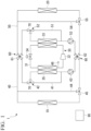
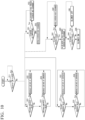
FIG. 1 is a circuit diagram showing a configuration of a vehicular refrigeration cycle unit according to a first embodiment of the present disclosure. -
FIG. 2 is a circuit diagram showing a configuration of the vehicular refrigeration cycle unit according to the first embodiment of the present disclosure and is a diagram showing an operation state in a heat pump mode. -
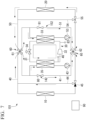
FIG. 3 is a circuit diagram showing a configuration of the vehicular refrigeration cycle unit according to the first embodiment of the present disclosure and is a diagram showing an operation state in a heater mode. -
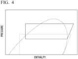
FIG. 4 is a graph showing a comparison of Mollier diagrams in a heater mode and a heat pump mode. -
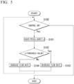
FIG. 5 is a flowchart showing a process flow of a control unit according to the first embodiment of the present disclosure. -
FIG. 6 is a circuit diagram showing a configuration of a vehicular refrigeration cycle unit according to a second embodiment of the present disclosure and is a diagram showing an operation state in a heater mode. -
FIG. 7 is a circuit diagram showing a configuration of a vehicular refrigeration cycle unit according to a third embodiment of the present disclosure and is a diagram showing one aspect of control when starting a heater mode. -
FIG. 8 is a circuit diagram showing a configuration of the vehicular refrigeration cycle unit according to the third embodiment of the present disclosure and is a diagram showing another aspect of control when starting a heater mode. -
FIG. 9 is a circuit diagram showing a configuration of the vehicular refrigeration cycle unit according to the third embodiment of the present disclosure and is a diagram showing still another aspect of control when operating a heater mode. -
FIG. 10 is a flowchart showing a process flow of a control unit according to the third embodiment of the present disclosure. - Hereinafter, a vehicular
refrigeration cycle unit 1 according to a first embodiment of the present disclosure will be described with reference toFIGS. 1 to 5 . - The vehicular
refrigeration cycle unit 1 according to this embodiment is air conditioning equipment installed in a transportation vehicle such as an electric vehicle that does not have an engine as a heat source during heating. The vehicularrefrigeration cycle unit 1 is mounted to be interposed between a vehicleexterior heat exchanger 10 disposed on a vehicle exterior side and a vehicleinterior heat exchanger 20 disposed on a vehicle interior side. The refrigerant (coolant) flowing through the vehicleexterior heat exchanger 10 and the vehicleinterior heat exchanger 20 is hereinafter referred to as a "secondary refrigerant" and the refrigerant flowing through a refrigeration cycle 30 (described later) is referred to as a "primary refrigerant". - As shown in
FIG. 1 , the vehicularrefrigeration cycle unit 1 includes therefrigeration cycle 30 through which the primary refrigerant flows, anexterior flow passage 40 which is disposed on an exterior side, aninterior flow passage 50 which is disposed on an interior side, a pair of flowpassage switching valves 60 which switches the mutual flow state of theexterior flow passage 40 and theinterior flow passage 50, a firstbypass flow passage 41 which is alongside theexterior flow passage 40, a first flowrate adjustment unit 42, a secondbypass flow passage 51 which is alongside theinterior flow passage 50, a second flowrate adjustment unit 52, afirst pump 43 which is provided on theexterior flow passage 40, asecond pump 53 which is provided on theinterior flow passage 50, an exteriorconnection flow passage 44, afirst switching valve 45, an interiorconnection flow passage 54, asecond switching valve 55, ameasurement unit 46, and acontrol unit 90. - Additionally, in the drawings, if various valves of the vehicular
refrigeration cycle unit 1 are painted black, they are in a closed state and if these valves are painted white, they are in an open state. Further, the directions in which various refrigerants flow are indicated by arrows drawn along the circuits. - The
refrigeration cycle 30 is composed of a plurality of devices that realize a thermodynamic cycle. Therefrigeration cycle 30 is a refrigerant circuit that allows the primary refrigerant as a heat medium to sequentially flow and circulate in a plurality of devices while repeatedly compressing, expanding, evaporating, and condensing the primary refrigerant in order to exchange heat between the primary refrigerant and the secondary refrigerant. - The
refrigeration cycle 30 includes arefrigeration cycle line 31 and acompressor 32, acondenser 33, anexpansion valve 34, and anevaporator 35 sequentially arranged on thisrefrigeration cycle line 31. - The
evaporator 35 is a plate heat exchanger that evaporates (vaporizes) the primary refrigerant by exchanging heat between the primary refrigerant sequentially flows through therefrigeration cycle 30 and the secondary refrigerant introduced from the outside of therefrigeration cycle 30. The primary refrigerant inside theevaporator 35 absorbs heat from the secondary refrigerant and simultaneously cools the secondary refrigerant. - The
compressor 32 is a device that absorbs heat and compresses the vaporized primary refrigerant by passing through theevaporator 35. The pressure of the primary refrigerant introduced into thecompressor 32 is increased to a predetermined pressure higher than before compression by the compression operation of thecompressor 32. Accordingly, the temperature of the primary refrigerant becomes higher than before compression. - The
condenser 33 is a plate heat exchanger that condenses (liquefies) the primary refrigerant by exchanging heat between the primary refrigerant passing through thecompressor 32 to have a temperature and a pressure higher than before compression and the secondary refrigerant introduced from the outside of therefrigeration cycle 30. - The primary refrigerant inside the
condenser 33 is cooled by the secondary refrigerant and simultaneously increases the temperature of the secondary refrigerant. - The primary refrigerant in a gas state introduced into the
condenser 33 is cooled by the secondary refrigerant, passes through a two-phase state of a gas-liquid mixture, and then transitions to a liquid state. - The
expansion valve 34 is a device that receives the primary refrigerant changing into a liquid state via thecondenser 33 and adiabatically expands the primary refrigerant. The pressure of the primary refrigerant introduced to theexpansion valve 34 is decreased to a predetermined pressure lower than before expansion due to the expansion action of theexpansion valve 34. Accordingly, the temperature of the primary refrigerant becomes lower than before expansion. - The
exterior flow passage 40 is a flow passage that connects theevaporator 35 in therefrigeration cycle 30 and the vehicleexterior heat exchanger 10 in an annular shape. The secondary refrigerant flows through theexterior flow passage 40. Thefirst pump 43, thefirst switching valve 45, and the exteriorconnection flow passage 44 are provided on theexterior flow passage 40. Thefirst pump 43 pressure-feeds the secondary refrigerant flowing through theexterior flow passage 40. Thefirst switching valve 45 is a three-way valve that can switch the flow state between three flow passages. The exteriorconnection flow passage 44 extends with bypassing the vehicleexterior heat exchanger 10 from thefirst switching valve 45 as a start point. Thefirst switching valve 45 is electrically connected to thecontrol unit 90 to be described later and the flow state of the secondary refrigerant is switched by the electric signal sent from thecontrol unit 90. - The first
bypass flow passage 41 is provided alongside theexterior flow passage 40 and extends with bypassing theevaporator 35. A flowrate adjustment valve 70 is provided at one end of the firstbypass flow passage 41 as the first flowrate adjustment unit 42. The flowrate adjustment valve 70 is a three-way valve. That is, the flowrate adjustment valve 70 can distribute the secondary refrigerant flowing from one flow passage into two flow passages and change the ratio of the flow rate of the secondary refrigerant between these two flow passages. - Specifically, the first flow
rate adjustment unit 42 changes the ratio of the flow rate of the secondary refrigerant flowing into theevaporator 35 via theexterior flow passage 40 and the flow rate of the secondary refrigerant flowing into the firstbypass flow passage 41. The ratio of the flow rate is realized by changing the internal structure of the valve of the flowrate adjustment valve 70. The flowrate adjustment valve 70 is electrically connected to the control unit 90 (to be described later). The internal structure of the valve is controlled based on the electric signal sent from thecontrol unit 90. - The
interior flow passage 50 is a flow passage that connects thecondenser 33 in therefrigeration cycle 30 and the vehicleinterior heat exchanger 20 in an annular shape. The secondary refrigerant flows through theinterior flow passage 50. Thesecond pump 53, thesecond switching valve 55, and the interiorconnection flow passage 54 are provided on thisinterior flow passage 50. Thesecond pump 53 pressure-feeds the secondary refrigerant flowing through theinterior flow passage 50. Thesecond switching valve 55 is a three-way valve similarly to thefirst switching valve 45. Thesecond switching valve 55 is electrically connected to thecontrol unit 90 to be described later and the flow state of the secondary refrigerant is switched by the electric signal sent from thecontrol unit 90. The interiorconnection flow passage 54 extends with bypassing the vehicleinterior heat exchanger 20 from thesecond switching valve 55 as a start point. - The second
bypass flow passage 51 is provided alongside theinterior flow passage 50 and extends with bypassing thecondenser 33. The flowrate adjustment valve 70 is provided at one end of the secondbypass flow passage 51 as the second flowrate adjustment unit 52. The flowrate adjustment valve 70 is a three-way valve. That is, the flowrate adjustment valve 70 can distribute the secondary refrigerant flowing from one flow passage into two flow passages and change the ratio of the flow rate of the secondary refrigerant between these two flow passages. - Specifically, the second flow
rate adjustment unit 52 changes the ratio of the flow rate of the secondary refrigerant flowing into thecondenser 33 via theinterior flow passage 50 and the flow rate of the secondary refrigerant flowing into the secondbypass flow passage 51. The ratio of the flow rate is controlled based on the electric signal sent from thecontrol unit 90 similarly to the first flowrate adjustment unit 42. - The
exterior flow passage 40 and theinterior flow passage 50 are connected by the pair of flow passage switching valves 60 (a first flowpassage switching valve 61 and a second flow passage switching valve 62). More specifically, the first flowpassage switching valve 61 is provided between the vehicleexterior heat exchanger 10 in theexterior flow passage 40 and the first flowrate adjustment unit 42 and between the vehicleinterior heat exchanger 20 in theinterior flow passage 50 and the second flowrate adjustment unit 52. Further, the second flowpassage switching valve 62 is provided between thefirst switching valve 45 in theexterior flow passage 40 and thefirst pump 43 and between thesecond switching valve 55 in theinterior flow passage 50 and thesecond pump 53. - As will be described later, the flow state of the secondary refrigerant between the
exterior flow passage 40 and theinterior flow passage 50 is mutually switched by providing the first flowpassage switching valve 61 and the second flowpassage switching valve 62. The first flowpassage switching valve 61 and the second flowpassage switching valve 62 are electrically connected to the control unit 90 (to be described later) and the flow state is switched based on the electric signal sent from thecontrol unit 90. - The
measurement unit 46 measures a physical quantity related to the pressure of the primary refrigerant on the downstream side of theevaporator 35 in therefrigeration cycle line 31. Additionally, the physical quantity mentioned herein may be the pressure of the primary refrigerant itself or the temperature of the primary refrigerant. That is, themeasurement unit 46 is a pressure gauge or a thermometer. The physical quantity measured by themeasurement unit 46 is sent to thecontrol unit 90 as the electric signal. Thecontrol unit 90 adjusts the flow state of the first flowrate adjustment unit 42 based on the measurement result of themeasurement unit 46. - Next, the process flow of the control of the first flow
rate adjustment unit 42 using thecontrol unit 90 will be described with reference toFIG. 5 . First, in step S100, it is determined whether or not the control using thecontrol unit 90 is in an on state. In the case of an off state (step S100: No), the process ends. In the case of an on state (step S 100: Yes), thecontrol unit 90 acquires a physical quantity p related to the pressure of the primary refrigerant from themeasurement unit 46 in step S 101 below. Next, in step S 102, thecontrol unit 90 determines the magnitude relationship between the physical quantity p and the threshold value. When it is determined that the physical quantity p is larger than the threshold value (step S 102: Yes), the process proceeds to step S 103. In step S103, thecontrol unit 90 sends an electric signal to the first flow rate adjustment unit 42 (the flow rate adjustment valve 70) so that the flow rate of the secondary refrigerant flowing into the evaporator 35 changes in a decrease direction. On the other hand, when it is determined that the physical quantity p is smaller than the threshold value (step S102: No), the process proceeds to step S104. In step S104, thecontrol unit 90 sends an electric signal to the first flow rate adjustment unit 42 (the flow rate adjustment valve 70) so that the flow rate of the secondary refrigerant flowing into the evaporator 35 changes in an increase direction. In this way, the flow state of the first flowrate adjustment unit 42 is controlled based on the physical quantity of the primary refrigerant flowing out from theevaporator 35. - Next, two operation modes during a heating operation among various operation modes of the vehicular
refrigeration cycle unit 1 will be described. During the heating operation, the operation mode is appropriately selected between a heater mode that is used when the outside air temperature is particularly low (for example, about -20°C) and a heat pump mode that is used when the outside air temperature is higher than that of the heater mode. - First, the operation of the heat pump mode during the heating operation will be described with reference to
FIG. 2 . As shown in the same drawing, the flow state of the first flowpassage switching valve 61 and the second flowpassage switching valve 62 is switched so that theexterior flow passage 40 and theinterior flow passage 50 are independent of each other in this mode. Further, the exteriorconnection flow passage 44 and the interiorconnection flow passage 54 are respectively closed by thefirst switching valve 45 and thesecond switching valve 55. The firstbypass flow passage 41 and the secondbypass flow passage 51 are respectively closed by the first flowrate adjustment unit 42 and the second flowrate adjustment unit 52. - Accordingly, the secondary refrigerant flows through the path indicated by the arrow in
FIG. 2 . Specifically, in theexterior flow passage 40, the secondary refrigerant passing through the second flowpassage switching valve 62 via thefirst pump 43 flows into the vehicleexterior heat exchanger 10 and then flows toward the first flowpassage switching valve 61. Then, the secondary refrigerant flows into theevaporator 35 via the first flowrate adjustment unit 42. The secondary refrigerant exchanging heat with the primary refrigerant of therefrigeration cycle 30 in theevaporator 35 is in a low temperature state. The secondary refrigerant flowing out from theevaporator 35 flows into thefirst pump 43 again. Such a flow occurs continuously. - In the
interior flow passage 50, the secondary refrigerant passing through the second flowpassage switching valve 62 via thesecond pump 53 exchanges heat with interior air in the vehicleinterior heat exchanger 20. Accordingly, the secondary refrigerant becomes a low temperature state and flows toward the first flowpassage switching valve 61. Then, the secondary refrigerant flows to thecondenser 33 via the second flowrate adjustment unit 52. The secondary refrigerant exchanging heat with the primary refrigerant in thecondenser 33 becomes a high temperature state. The secondary refrigerant flowing out from thecondenser 33 flows into thesecond pump 53 again. Such a flow occurs continuously. - With the above-described state, heat is exchanged between the primary refrigerant and the secondary refrigerant. Specifically, heat is exchanged between the relatively high-temperature outside air and the relatively low-temperature secondary refrigerant in the vehicle
exterior heat exchanger 10. The heat of the secondary refrigerant heated by heat exchange with the outside air is transferred to the secondary refrigerant in theinterior flow passage 50 via therefrigeration cycle 30. The secondary refrigerant in theinterior flow passage 50 exchanges heat with the interior air in the vehicleinterior heat exchanger 20. Accordingly, the interior temperature increases. - On the other hand, the open and close states of various valves and the flow state of the secondary refrigerant are as shown in
FIG. 3 during a stationary operation of the heater mode. Specifically, the exteriorconnection flow passage 44 is opened by thefirst switching valve 45 and the secondary refrigerant flows with bypassing the vehicleexterior heat exchanger 10. In the first flowpassage switching valve 61, the flow state is switched so that the secondary refrigerant flowing through theinterior flow passage 50 flows into theexterior flow passage 40 and the secondary refrigerant flowing through theexterior flow passage 40 flows into theinterior flow passage 50. In the second flowpassage switching valve 62, the flow state is switched so that the secondary refrigerant discharged from thefirst pump 43 flows through theexterior flow passage 40 and the secondary refrigerant discharged from thesecond pump 53 flows through theinterior flow passage 50. - In the first flow
rate adjustment unit 42, the secondary refrigerant which flows from theinterior flow passage 50 into theexterior flow passage 40 via the first flowpassage switching valve 61 is distributed to the side of theevaporator 35 and the side of the firstbypass flow passage 41. The ratio of the flow rate of the secondary refrigerant flowing through theevaporator 35 and the flow rate of the secondary refrigerant flowing through the firstbypass flow passage 41 is controlled by the above-described control flow. - In the second flow
rate adjustment unit 52, the secondary refrigerant which flows from theexterior flow passage 40 into theinterior flow passage 50 via the first flowpassage switching valve 61 is controlled to flow not to the secondbypass flow passage 51 but to thecondenser 33. - Accordingly, the secondary refrigerant flows through the path indicated by the arrow in
FIG. 3 . Specifically, the secondary refrigerant discharged from thefirst pump 43 flows toward thefirst switching valve 45 via the second flowpassage switching valve 62 on the side of theevaporator 35. The secondary refrigerant flowing into the exteriorconnection flow passage 44 via thefirst switching valve 45 flows into theinterior flow passage 50 via the first flowpassage switching valve 61. The secondary refrigerant flowing into theinterior flow passage 50 flows into thecondenser 33 via the second flowrate adjustment unit 52. The secondary refrigerant that exchanges heat with the primary refrigerant in thecondenser 33 becomes a high temperature state and flows into thesecond pump 53. The secondary refrigerant discharged from thesecond pump 53 flows through theinterior flow passage 50 again via the second flowpassage switching valve 62 and heads toward the vehicleinterior heat exchanger 20. - The secondary refrigerant that exchanges heat with the interior air in the vehicle
interior heat exchanger 20 becomes a low temperature state and heads toward the first flowpassage switching valve 61 through theinterior flow passage 50. The secondary refrigerant flowing into theexterior flow passage 40 via the first flowpassage switching valve 61 is distributed to the flow toward theevaporator 35 and the flow toward the firstbypass flow passage 41 via the first flowrate adjustment unit 42. In theevaporator 35, heat is exchanged between the secondary refrigerant and the primary refrigerant. Accordingly, the secondary refrigerant becomes a low-temperature state. These two flows merge on the downstream side of theevaporator 35 and then heads toward thefirst pump 43. The above-described flow of the secondary refrigerant continuously occurs. - With the above-described state, the relatively high-temperature secondary refrigerant flows from the
interior flow passage 50 into theevaporator 35. Accordingly, the temperature of the primary refrigerant in therefrigeration cycle 30 that exchanges heat with the secondary refrigerant increases. As the temperature increases, the pressure and density of the primary refrigerant also increase. Since the density of the primary refrigerant increases, the load of thecompressor 32 also increases. In other words, the work amount of thecompressor 32 increases. As a result, the amount of heat generated in accordance with the operation of thecompressor 32 increases. This increased amount of heat is transferred to the primary refrigerant and then transferred to the secondary refrigerant flowing through theinterior flow passage 50 in thecondenser 33 on the downstream side of thecompressor 32. Accordingly, the temperature of the secondary refrigerant increases. The heated secondary refrigerant exchanges heat with the interior air in the vehicleinterior heat exchanger 20. As a result, the interior temperature increases (heating occurs). - In this way, since it is possible to heat the primary refrigerant by the amount of heat due to the increased load of the
compressor 32, it is possible to secure heating capacity without exchanging heat between the outside air and the secondary refrigerant using the vehicleexterior heat exchanger 10. Thus, there is no need to exchange heat between the secondary refrigerant and the outside air while the outside air temperature is too low. In other words, there is no need to make the temperature of the secondary refrigerant flowing through theexterior flow passage 40 lower than the outside air temperature. As a result, it is possible to perform the heating operation beyond the restriction imposed by the minimum temperature determined by the physical property values of the primary refrigerant. - Furthermore, since the pressure of the primary refrigerant flowing into the
compressor 32 increases as described above, the compression ratio of thecompressor 32 decreases. That is, the Mollier diagram in this case becomes the graph indicated by the solid line inFIG. 4 . Additionally, the dashed line inFIG. 4 indicates the Mollier diagram in the heat pump mode. When operating in the heater mode, the pressure shown on the vertical axis increases compared to the heat pump mode and the difference between the upper limit and the lower limit decreases compared to the heat pump mode. Accordingly, it is possible to operate thecompressor 32 at a pressure close to the upper limit value of the discharge pressure of thecompressor 32. As a result, the load of thecompressor 32 further increases and more heat can be generated by thecompressor 32. The heat generated by thecompressor 32 is transferred to the primary refrigerant and then transferred to the secondary refrigerant flowing through theinterior flow passage 50 in thecondenser 33. Accordingly, the temperature of the secondary refrigerant increases. The heated secondary refrigerant exchanges heat with the interior air in the vehicleinterior heat exchanger 20. As a result, it is possible to further improve the heating performance of the vehicularrefrigeration cycle unit 1. - Additionally, according to the above-described configuration, it is possible to adjust the temperature of the primary refrigerant flowing through the
evaporator 35 in therefrigeration cycle 30 by adjusting the flow rate of the secondary refrigerant flowing into theevaporator 35 using the first flowrate adjustment unit 42. Accordingly, since the pressure and density of the primary refrigerant change to desired values, it is possible to precisely adjust the load (work amount) of thecompressor 32. That is, it is possible to precisely control the amount of heat transferred from thecompressor 32 to the primary refrigerant. As a result, it is possible to precisely control the temperature of the secondary refrigerant during the heating operation. - Particularly, according to the above-described configuration, the
control unit 90 appropriately adjusts the flow state of the first flowrate adjustment unit 42 based on the physical quantity related to the pressure of the secondary refrigerant on the downstream side of theevaporator 35. Accordingly, the ratio of the flow rates of the secondary refrigerants flowing into theevaporator 35 and the firstbypass flow passage 41 changes autonomously. Thus, it is possible to more precisely control the amount of heat transferred from thecompressor 32 to the primary refrigerant. - Additionally, when starting the heater mode, the second flow
rate adjustment unit 52 is controlled so that the secondary refrigerant flows not to thecondenser 33 but to the secondbypass flow passage 51 contrary to the above description. Accordingly, the pressure of the primary refrigerant flowing through thecondenser 33 in therefrigeration cycle 30 increases. Then, when shifting to the above-described stationary operation, the second flowrate adjustment unit 52 is controlled so that the flow rate of the secondary refrigerant flowing into thecondenser 33 gradually increases. - By performing the above-described control, it is possible to control the pressure and temperature of the primary refrigerant flowing through the
condenser 33 in therefrigeration cycle 30. Particularly, at startup, the amount of the secondary refrigerant flowing through thecondenser 33 is minimized and the main flow is allowed to flow through the secondbypass flow passage 51. Accordingly, the flow amount of the low-temperature secondary refrigerant flowing from theexterior flow passage 40 toward theinterior flow passage 50 to flow into thecondenser 33 is reduced. As a result, the pressure and temperature of the primary refrigerant in therefrigeration cycle 30 increase quickly. Thus, since the temperature of the secondary refrigerant exchanging heat with the primary refrigerant also increases quickly, it is possible to quickly heat the temperature of the interior air during the heating operation. - Furthermore, according to the above-described configuration, since the flow
rate adjustment valve 70 is used as the first flowrate adjustment unit 42 and the second flowrate adjustment unit 52, it is possible to suppress an increase in the number of parts and avoid complicating the configuration. As a result, it is possible to more easily perform manufacturing and maintenance of the vehicularrefrigeration cycle unit 1 at a lower cost. - As described above, the first embodiment of the present disclosure has been described. Additionally, various changes and modifications can be made to each of the above configurations without departing from the gist of the present disclosure. For example, in the above-described first embodiment, an example has been described in which the secondary refrigerant does not flow into the vehicle
exterior heat exchanger 10 at all by switching thefirst switching valve 45 in the heater mode. However, thefirst switching valve 45 may be controlled so that a small flow rate of the secondary refrigerant flows through the vehicleexterior heat exchanger 10 depending on the outside air temperature or operation state. - Next, a second embodiment of the present disclosure will be described with reference to
FIG. 6 . Additionally, the same configurations as those of the first embodiment are denoted by the same reference numerals and detailed descriptions are omitted. In a vehicularrefrigeration cycle unit 101 according to this embodiment, the configurations of a first flowrate adjustment unit 142 and a second flowrate adjustment unit 152 are different from those of the first embodiment. - Specifically, in this embodiment, the first flow
rate adjustment unit 142 and the second flowrate adjustment unit 152 are configured by on-offvalves rate adjustment valve 70. These on-offvalves bypass flow passage 41 and the secondbypass flow passage 51. The on-offvalves control unit 90 and the opening and closing state is switched by the electric signal sent from thecontrol unit 90. - Furthermore, the confluence of the first
bypass flow passage 41 and theexterior flow passage 40 is located on the downstream side of thefirst pump 43. Similarly, the confluence of the secondbypass flow passage 51 and theinterior flow passage 50 is located on the downstream side of thesecond pump 53. - The
first pump 43 and thesecond pump 53 have variable rotation speeds and can change the discharge flow rate. Thefirst pump 43 and thesecond pump 53 are electrically connected to thecontrol unit 90 and the discharge flow rate is controlled by the electric signal sent from a drive unit 94 of thecontrol unit 90. Thefirst pump 43 constitutes part of the first flowrate adjustment unit 142 and thesecond pump 53 constitutes part of the second flowrate adjustment unit 152. -
FIG. 6 shows a state in which the vehicularrefrigeration cycle unit 101 is operated in the heater mode. In the heater mode, the on-offvalve 80 which is part of the first flowrate adjustment unit 142 is kept open. By changing the discharge flow rate of thefirst pump 43 which is a part of the first flowrate adjustment unit 142 in this state, the ratio of the flow rate of the secondary refrigerant flowing into theevaporator 35 and the flow rate of the secondary refrigerant flowing into the firstbypass flow passage 41 is adjusted. - According to the above-described configuration, in addition to the operation and effect described in the first embodiment, since the on-off
valves rate adjustment valve 70, it is possible to reduce the costs required for manufacturing and maintenance of the device. Further, since the flow rate of the secondary refrigerant is controlled by controlling the discharge flow rates of thefirst pump 43 and thesecond pump 53, it is possible to more precisely adjust the temperature of the secondary refrigerant compared to a condition where the same flow rate control is performed using the flowrate adjustment valve 70. - As described above, the second embodiment of the present disclosure has been described. Additionally, various changes and modifications can be made to the above configuration without departing from the gist of the present disclosure.
- Next, a third embodiment of the present disclosure will be described with reference to
FIGS. 7 to 10 . Additionally, the same configurations as those of the above-described embodiments are denoted by the same reference numerals and detailed descriptions are omitted. - In this embodiment, various controls and configurations for accelerating the startup of the heater mode will be described. A vehicular
refrigeration cycle unit 201 according to this embodiment further includes a firsttemperature measurement unit 47, a secondtemperature measurement unit 48, a thirdtemperature measurement unit 49, and apressure measurement unit 83 in addition to each configuration described in the second embodiment. The firsttemperature measurement unit 47 measures the temperature of the secondary refrigerant on the downstream side of the confluence between the firstbypass flow passage 41 and theexterior flow passage 40. The secondtemperature measurement unit 48 measures the temperature of the primary refrigerant at the inlet of thecompressor 32. The thirdtemperature measurement unit 49 measures the temperature of the secondary refrigerant on the downstream side of the confluence between theinterior flow passage 50 and the secondbypass flow passage 51. The firsttemperature measurement unit 47, the secondtemperature measurement unit 48, and the thirdtemperature measurement unit 49 are temperature sensors or thermometers. Additionally, the firsttemperature measurement unit 47, the secondtemperature measurement unit 48, and the thirdtemperature measurement unit 49 are not shown inFIG. 7 . Thepressure measurement unit 83 measures the pressure (high pressure side pressure) of the primary refrigerant on the downstream side of thecompressor 32. Thepressure measurement unit 83 is a pressure sensor or pressure gauge. Further, in this embodiment, ablower 21 provided alongside the vehicleinterior heat exchanger 20 is shown. - In a condition where the pressure (high pressure side pressure) of the primary refrigerant measured by the
pressure measurement unit 83 is lower than a predetermined threshold value when starting the heater mode, the flow rate of the secondary refrigerant flowing into thecondenser 33 is decreased as shown inFIG. 7 . - The above-described control is realized by steps S21 to S24 in the control flow shown in
FIG. 10 . In step S21, it is determined whether or not the pressure of the primary refrigerant measured by thepressure measurement unit 83 is higher than the threshold value. When it is determined that the pressure is higher than the threshold value (step S21: Yes), the condenser flow rate is increased in step S22. When the determination in step S21 is No, it is determined whether or not the pressure of the primary refrigerant measured by thepressure measurement unit 83 is lower than the threshold value in step S23. When the determination in step S23 is Yes, the condenser flow rate is decreased in step S24. - Since the flow of the secondary refrigerant to the
condenser 33 when starting the vehicularrefrigeration cycle unit 201 is reduced in this way, the temperature of the primary refrigerant is increased for a temperature difference with the secondary refrigerant to radiate heat from the primary refrigerant in thecondenser 33. As a result, the pressure and temperature of the primary refrigerant increase quickly. Accordingly, it is possible to quickly heat the interior air. - In addition to the above, as shown in
FIG. 9 , in a condition where the temperature T1 of the secondary refrigerant measured by the firsttemperature measurement unit 47 is higher than the outside air temperature when starting the heater mode, thecontrol unit 90 switches the flow state of thefirst switching valve 45 so that the secondary refrigerant flows into the exteriorconnection flow passage 44. On the other hand, in another condition where the temperature of the secondary refrigerant measured by the firsttemperature measurement unit 47 is lower than the outside air temperature, the control unit switches the flow state of thefirst switching valve 45 so that the secondary refrigerant flows into the vehicleexterior heat exchanger 10. - The above-described control is realized by steps S51 to S53 in the control flow shown in
FIG. 10 . In step S51, it is determined whether or not the temperature T1 of the secondary refrigerant measured by the firsttemperature measurement unit 47 is lower than the outside air temperature. When the determination in step S51 is Yes, the flow state of thefirst switching valve 45 is switched so that the secondary refrigerant flows into the vehicleexterior heat exchanger 10 in step S52. On the other hand, when the determination in step S51 is No, the flow state of thefirst switching valve 45 is switched so that the secondary refrigerant flows into the exteriorconnection flow passage 44 with bypassing the vehicleexterior heat exchanger 10 in step S53. - Here, since the heating performance decreases in the condition where the heat amount of the secondary refrigerant decreases, the secondary refrigerant bypasses the vehicle
exterior heat exchanger 10 using the exteriorconnection flow passage 44 when the temperature of the secondary refrigerant is higher than the outside air temperature. Accordingly, it is possible to prevent a decrease in the heat amount of the secondary refrigerant and to prevent a decrease in the pressure (low pressure side pressure) of the primary medium on the side of theevaporator 35. Thus, it is possible to quickly obtain a heating effect when starting the vehicularrefrigeration cycle unit 1. - As another control for accelerating the startup of the heater mode, as shown in
FIG. 8 , thecontrol unit 90 increases the flow rate of the secondary refrigerant flowing into the evaporator in a condition where the temperature T2 of the primary refrigerant at the inlet of thecompressor 32 measured by the secondtemperature measurement unit 48 is lower than a predetermined first threshold value when starting the vehicularrefrigeration cycle unit 1. - The above-described control is realized by steps S31 to S34 in the control flow shown in
FIG. 10 . In step S31, it is determined whether or not the temperature of the primary refrigerant measured by the secondtemperature measurement unit 48 is higher than the first threshold value. When it is determined that the temperature is higher than the first threshold value (step S31: Yes), the evaporator flow rate is decreased in step S32. On the other hand, when the determination in step S31 is No, it is determined whether or not the temperature of the primary refrigerant measured by the secondtemperature measurement unit 48 is lower than the threshold value in step S33. When the determination in step S33 is Yes, the evaporator flow rate is increased in step S34. - According to the above-described configuration, it is possible to control the pressure and temperature of the primary refrigerant flowing through the
evaporator 35 by adjusting the amount of the secondary refrigerant flowing into theevaporator 35. In particular, the pressure and temperature of the primary refrigerant increase quickly by allowing the secondary refrigerant to flow through theevaporator 35 at startup. Accordingly, it is possible to quickly heat the interior air. - Specifically, when the flow rate of the secondary refrigerant flowing out from the
condenser 33 and flowing through theevaporator 35 increases, the amount of heat absorbed from the secondary refrigerant to the primary refrigerant increases and the low pressure side pressure of the primary refrigerant increases. When the low pressure side pressure of the primary refrigerant increases, the temperature of the primary refrigerant at the inlet of thecompressor 32 increases and hence the refrigerant density of the primary refrigerant at the inlet of thecompressor 32 also increases. Therefore, even when the rotation speed of the compressor is the same, the circulation amount of the primary refrigerant increases and hence the power of thecompressor 32 increases. Since the power of thecompressor 32 increases, the high pressure side pressure of the primary refrigerant also increases due to the heat generated in thecompressor 32. Then, the temperature of the secondary refrigerant in thecondenser 33 also increases and the temperature of the secondary refrigerant flowing out from thecondenser 33 and supplied to the vehicleinterior heat exchanger 20 also increases. As a result, it is possible to more quickly increase the temperature of the air supplied into the vehicle interior. - Furthermore, as shown in
FIG. 9 , in a condition where the temperature T3 of the secondary refrigerant measured by the thirdtemperature measurement unit 49 is lower than a predetermined second threshold value when starting the heater mode, thecontrol unit 90 switches the flow state of thesecond switching valve 55 so that the secondary refrigerant flows into the interiorconnection flow passage 54. On the other hand, in another condition where the temperature T3 of the secondary refrigerant measured by the thirdtemperature measurement unit 49 is higher than the predetermined second threshold value, the control unit switches the flow state of thesecond switching valve 55 so that the secondary refrigerant flows into the vehicleinterior heat exchanger 20. - Furthermore, when the temperature T3 of the secondary refrigerant measured by the third
temperature measurement unit 49 is lower than a predetermined third threshold value when starting the heater mode, thecontrol unit 90 stops theblower 21. That is, when the temperature of the secondary refrigerant is lower than the third threshold value, the supply of warm air to the vehicle interior is stopped. On the other hand, when the temperature of the secondary refrigerant increases and becomes higher than the third threshold value, theblower 21 is driven to start the supply of warm air to the vehicle interior. - The above-described control is realized by steps S41 to S46 in the control flow shown in
FIG. 10 . In step S41, it is determined whether or not the temperature T3 of the secondary refrigerant measured by the thirdtemperature measurement unit 49 is lower than the predetermined second threshold value. When the determination in step S41 is Yes, the process proceeds to step S42. In step S42, the flow state of thesecond switching valve 55 is switched so that the secondary refrigerant flows into the interiorconnection flow passage 54 with bypassing the vehicleinterior heat exchanger 20. On the other hand, when the determination in step S41 is No, the flow state of thesecond switching valve 55 is switched so that the secondary refrigerant flows into the vehicleinterior heat exchanger 20 in step S43. Further, in step S44, it is determined whether or not the temperature T3 of the secondary refrigerant measured by the thirdtemperature measurement unit 49 is lower than the predetermined third threshold value. When the determination in step S44 is Yes, the driving of theblower 21 is stopped in step S45. On the other hand, when the determination in step S44 is No, theblower 21 is driven in step S46. - According to the above-described configuration, in the condition where the temperature of the secondary refrigerant on the downstream side of the confluence between the
interior flow passage 50 and the secondbypass flow passage 51 is lower than the second threshold value when starting the vehicularrefrigeration cycle unit 1, thesecond switching valve 55 is switched so that the secondary refrigerant is not supplied to the vehicleinterior heat exchanger 20 and flows into the interiorconnection flow passage 54. Accordingly, the amount of the secondary refrigerant to be heated by thecondenser 33 can be reduced. As the heat capacity of the secondary refrigerant decreases, the temperature increases faster and hence the temperature of the secondary refrigerant increases faster. Thus, it is possible to quickly obtain a heating effect when starting the vehicularrefrigeration cycle unit 1. - Furthermore, according to the above-described configuration, the supply of air to the vehicle
interior heat exchanger 20 using theblower 21 stops until the temperature of the secondary refrigerant on the downstream side of the confluence between theinterior flow passage 50 and the secondbypass flow passage 51 reaches the third threshold value. Accordingly, the heat exchange between the secondary refrigerant and air in the vehicleinterior heat exchanger 20 is suppressed. As a result, the temperature of the secondary refrigerant increases quickly. Thus, it is possible to shorten the time until the temperature of the air finally supplied into the vehicle interior from the vehicleinterior heat exchanger 20 reaches the set temperature. - As described above, the embodiments of the present disclosure have been described. Additionally, various changes and modifications can be made to the above configuration without departing from the gist of the present disclosure. For example, the process flow of the
control unit 90 in each of the above-described embodiments may be performed by changing the process order in an appropriate process range. - Further, the "
exterior flow passage 40" and the "interior flow passage 50" do not necessarily mean that they are provided only outside the vehicle interior or only inside the vehicle interior. That is, part of theexterior flow passage 40 may be provided inside the vehicle interior when necessary and a part of theinterior flow passage 50 may be provided outside the vehicle interior. - Furthermore, all of the four control flows described in the third embodiment may be implemented in the
control unit 90 and all of them may be performed simultaneously or only four or less appropriately selected control flows may be implemented and performed. - The vehicular
refrigeration cycle unit 1 described in each embodiment is understood, for example, as below. - (1) The vehicular refrigeration cycle unit 1 according to a first aspect is the vehicular refrigeration cycle unit 1 which is installed between the vehicle exterior heat exchanger 10 and the vehicle interior heat exchanger 20 and exchanging heat between the secondary refrigerants respectively flowing through the vehicle exterior heat exchanger 10 and the vehicle interior heat exchanger 20, the vehicular refrigeration cycle unit including: the refrigeration cycle 30 including the compressor 32, the condenser 33, the expansion valve 34, and the evaporator 35 through which the primary refrigerant sequentially flows; the exterior flow passage 40 through which the secondary refrigerant is circulated between the evaporator 35 and the vehicle exterior heat exchanger 10; the interior flow passage 50 through which the secondary refrigerant is circulated between the condenser 33 and the vehicle interior heat exchanger 20; the pair of flow passage switching valves 60 connecting the exterior flow passage 40 and the interior flow passage 50 to allow to switch the flow state of the secondary refrigerant; the first bypass flow passage 41 which is installed aside the exterior flow passage 40 and with bypassing the evaporator 35; and the first flow rate adjustment unit 42 adjusting the flow rate of the secondary refrigerant flowing into the first bypass flow passage 41 and the evaporator 35, wherein the first flow rate adjustment unit 42 is the flow passage switching valve distributing the secondary refrigerant flowing from one flow passage into two flow passage and is allowed to change the ratio of the flow rate of the secondary refrigerant between these two flow passages.
According to the above-described configuration, it is possible to precisely adjust the load of thecompressor 32 by adjusting the amount of the secondary refrigerant flowing into theevaporator 35 using the first flowrate adjustment unit 42. Accordingly, it is possible to precisely control the amount of heat transferred from thecompressor 32 to the primary refrigerant. - (2) The vehicular
refrigeration cycle unit 1 according to a second aspect is the vehicularrefrigeration cycle unit 1 of (1), wherein the first flowrate adjustment unit 42 includes the on-offvalve 80 installed in the firstbypass flow passage 41 and thefirst pump 43 installed in theexterior flow passage 40.
According to the above-described configuration, it is possible to configure the device at a low cost by configuring the first flowrate adjustment unit 42 only with the on-offvalve 80 and thefirst pump 43. - (3) The vehicular
refrigeration cycle unit 1 according to a third aspect is the vehicularrefrigeration cycle unit 1 of (1) or (2) further including: thecontrol unit 90 switching the states of the pair of flowpassage switching valves 60 and the first flowrate adjustment unit 42, wherein the flow states of the flowpassage switching valves 60 are switched by thecontrol unit 90 so that the secondary refrigerant, which has flowed out from the vehicleinterior heat exchanger 20 via theinterior flow passage 50, is flowed into at least one of theevaporator 35 and the firstbypass flow passage 41 via theexterior flow passage 40.
According to the above-described configuration, the high-temperature secondary refrigerant flowing out from the vehicleinterior heat exchanger 20 flows into theevaporator 35. Accordingly, the temperature and density of the primary refrigerant heading to thecompressor 32 from theevaporator 35 increase. As a result, the load of thecompressor 32 increases and hence the amount of heat transferred from thecompressor 32 to the primary refrigerant can be increased. - (4) The vehicular
refrigeration cycle unit 1 according to a fourth aspect is the vehicularrefrigeration cycle unit 1 of (3) further including: themeasurement unit 46 measuring the physical quantity related to the pressure of the primary refrigerant on the downstream side of theevaporator 35 in therefrigeration cycle 30, wherein the flow state of the first flowrate adjustment unit 42 is adjusted by thecontrol unit 90 based on the measurement result of themeasurement unit 46.
According to the above-described configuration, since the flow state of the first flowrate adjustment unit 42 is adjusted based on the physical quantity related to the pressure of the primary refrigerant on the downstream side of theevaporator 35, the ratio of the flow rate of the secondary refrigerant flowing into theevaporator 35 and the firstbypass flow passage 41 changes. Accordingly, it is possible to more precisely control the amount of heat transferred from thecompressor 32 to the primary refrigerant. - (5) The vehicular
refrigeration cycle unit 1 according to a fifth aspect is the vehicularrefrigeration cycle unit 1 of any one aspect of (1) to (4) further including: the secondbypass flow passage 51 which is installed aside theinterior flow passage 50 with bypassing thecondenser 33; and the second flowrate adjustment unit 52 adjusting the flow rate of the secondary refrigerant flowing into the secondbypass flow passage 51 and thecondenser 33.
According to the above-described configuration, it is possible to control the pressure and temperature of the primary refrigerant flowing through thecondenser 33 by adjusting the amount of the secondary refrigerant flowing into thecondenser 33 using the second flowrate adjustment unit 52. - (6) The vehicular
refrigeration cycle unit 1 according to a sixth aspect is the vehicularrefrigeration cycle unit 1 of (5), wherein the second flowrate adjustment unit 52 is the flow passage switching valve distributing the secondary refrigerant flowing from one flow passage into two flow passages and is allowed to change the ratio of the flow rate of the secondary refrigerant between these two flow passages.
According to the above-described configuration, it is possible to more easily perform the manufacturing or maintenance of the device by using the flow rate adjustment valve. - (7) The vehicular
refrigeration cycle unit 1 according to a seventh aspect is the vehicularrefrigeration cycle unit 1 of (5), wherein the second flowrate adjustment unit 52 includes the on-offvalve 81 installed in the secondbypass flow passage 51 and thesecond pump 53 installed in theinterior flow passage 50.
According to the above-described configuration, it is possible to configure the device at a low cost by configuring the second flowrate adjustment unit 52 only with the on-offvalve 81 and thesecond pump 53. - (8) The vehicular
refrigeration cycle unit 1 according to an eighth aspect is the vehicularrefrigeration cycle unit 1 of any one aspect of (5) to (7) further including: thecontrol unit 90 switching the states of the pair of flowpassage switching valves 60 and the second flowrate adjustment unit 52, wherein, when starting the vehicularrefrigeration cycle unit 1, the flow states of the flowpassage switching valves 60 and the second flowrate adjustment unit 52 are switched by thecontrol unit 90 so that the secondary refrigerant passing through theexterior flow passage 40 flows into the secondbypass flow passage 51 via theinterior flow passage 50, and wherein, during a stationary operation of the vehicularrefrigeration cycle unit 1, the flow state of the second flowrate adjustment unit 52 is switched by thecontrol unit 90 so that the secondary refrigerant flows into thecondenser 33.
According to the above-described configuration, it is possible to control the pressure and temperature of the primary refrigerant flowing through thecondenser 33 by adjusting the amount of the secondary refrigerant flowing through thecondenser 33 using the second flowrate adjustment unit 52. Particularly, at startup, since the secondary refrigerant does not flow through thecondenser 33, the pressure and temperature of the primary refrigerant increase quickly. Accordingly, it is possible to quickly heat the interior air. - (9) The vehicular
refrigeration cycle unit 1 according to a ninth aspect is the vehicularrefrigeration cycle unit 1 of (3) or (4), wherein, when starting the vehicularrefrigeration cycle unit 1,the flow states of the flowpassage switching valves 60 and the first flowrate adjustment unit 42 are switched by thecontrol unit 90 so that the secondary refrigerant passing through theinterior flow passage 50 flows into theevaporator 35 through theexterior flow passage 40, and wherein, during a stationary operation of the vehicularrefrigeration cycle unit 1, the flow state of the first flowrate adjustment unit 42 is switched by thecontrol unit 90 so that the secondary refrigerant flows into the firstbypass flow passage 41.
According to the above-described configuration, it is possible to control the pressure and temperature of the primary refrigerant flowing through theevaporator 35 by adjusting the amount of the secondary refrigerant flowing into theevaporator 35 using the first flowrate adjustment unit 42. Particularly, at startup, since the secondary refrigerant flows through theevaporator 35, the pressure and temperature of the primary refrigerant increase quickly. Accordingly, it is possible to quickly heat the interior air. - (10) The vehicular
refrigeration cycle unit 1 according to a tenth aspect is the vehicularrefrigeration cycle unit 1 of (9) further including: the exteriorconnection flow passage 44 which is installed aside theexterior flow passage 40 with bypassing the vehicleexterior heat exchanger 10; thefirst switching valve 45 switching the flow state of the exteriorconnection flow passage 44; and the firsttemperature measurement unit 47 measuring the temperature of the secondary refrigerant on the downstream side of the confluence between the firstbypass flow passage 41 and theexterior flow passage 40, wherein, when starting the vehicularrefrigeration cycle unit 1, the flow state of thefirst switching valve 45 is switched by thecontrol unit 90 so that the secondary refrigerant flows into the exteriorconnection flow passage 44 in a condition where the temperature of the secondary refrigerant measured by the firsttemperature measurement unit 47 is higher than the outside air temperature, and the flow state of thefirst switching valve 45 is switched by thecontrol unit 90 so that the secondary refrigerant flows into the vehicleexterior heat exchanger 10 in another condition where the temperature of the secondary refrigerant measured by the firsttemperature measurement unit 47 is lower than the outside air temperature.
Since the heating performance decreases when the heat amount of the secondary refrigerant decreases, the secondary refrigerant bypasses the vehicleexterior heat exchanger 10 using the exteriorconnection flow passage 44 when the temperature of the secondary refrigerant is higher than the outside air temperature. Accordingly, it is possible to prevent a decrease in the heat amount of the secondary refrigerant and to prevent a decrease in the pressure (low pressure side pressure) of the primary refrigerant on the side of theevaporator 35. Thus, it is possible to quickly obtain a heating effect when starting the vehicularrefrigeration cycle unit 1. - (11) The vehicular
refrigeration cycle unit 1 according to an eleventh aspect is the vehicularrefrigeration cycle unit 1 of (9) or (10) further including: the interiorconnection flow passage 54 which is installed aside theinterior flow passage 50 and with bypassing the vehicleinterior heat exchanger 20; thesecond switching valve 55 switching the flow state of the interiorconnection flow passage 54; and the secondtemperature measurement unit 48 measuring the temperature of the primary refrigerant at the inlet of thecompressor 32 of therefrigeration cycle 30, wherein, when starting the vehicularrefrigeration cycle unit 1, the flow state of thesecond switching valve 55 is switched by thecontrol unit 90 so that the secondary refrigerant flows into the interiorconnection flow passage 54 in a condition where the temperature of the primary refrigerant measured by the secondtemperature measurement unit 48 is lower than the predetermined first threshold value, and the flow state of thesecond switching valve 55 is switched by thecontrol unit 90 so that the secondary refrigerant flows into the vehicleinterior heat exchanger 20 in another condition where the temperature of the primary refrigerant measured by the secondtemperature measurement unit 48 is higher than the first threshold value.
According to the above-described configuration, the amount of the secondary refrigerant to be heated by thecondenser 33 can be reduced. As the heat capacity of the secondary refrigerant decreases, the temperature increases faster and hence the temperature of the secondary refrigerant increases faster. Thus, it is possible to quickly obtain a heating effect when starting the vehicularrefrigeration cycle unit 1. - (12) The vehicular
refrigeration cycle unit 1 according to a twelfth aspect is the vehicularrefrigeration cycle unit 1 of (8) further including: theblower 21 which is installed aside the vehicleinterior heat exchanger 20 and supplying air exchanging heat in the vehicleinterior heat exchanger 20 into the vehicle interior; and the thirdtemperature measurement unit 49 measuring the temperature of the secondary refrigerant on the downstream side of the confluence between theinterior flow passage 50 and the secondbypass flow passage 51, wherein, when starting the vehicularrefrigeration cycle unit 1, theblower 21 is stopped by thecontrol unit 90 in a condition where the temperature of the secondary refrigerant measured by the thirdtemperature measurement unit 49 is lower than the predetermined second threshold value, and theblower 21 is driven by thecontrol unit 90 in another condition where the temperature of the secondary refrigerant measured by the thirdtemperature measurement unit 49 is higher than the second threshold value. - According to the above-described configuration, the supply of air to the vehicle
interior heat exchanger 20 using theblower 21 stops until the temperature of the secondary refrigerant on the downstream side of the confluence between theinterior flow passage 50 and the secondbypass flow passage 51 reaches the second threshold value. Accordingly, it is possible to more quickly increase the temperature of the air supplied from the vehicleinterior heat exchanger 20 into the vehicle interior. - In the vehicular refrigeration cycle unit, it is possible to more precisely adjust the temperature of the secondary refrigerant.
-
- 1 Vehicular refrigeration cycle unit
- 10 Vehicle exterior heat exchanger
- 20 Vehicle interior heat exchanger
- 21 Blower
- 30 Refrigeration cycle
- 31 Refrigeration cycle line
- 32 Compressor
- 33 Condenser
- 34 Expansion valve
- 35 Evaporator
- 40 Outdoor flow passage
- 41 First bypass flow passage
- 42 First flow rate adjustment unit
- 43 First pump
- 44 Outdoor connection flow passage
- 45 First switching valve
- 46 Measurement unit
- 47 First temperature measurement unit
- 48 Second temperature measurement unit
- 49 Third temperature measurement unit
- 50 Indoor flow passage
- 51 Second bypass flow passage
- 52 Second flow rate adjustment unit
- 53 Second pump
- 54 Interior connection flow passage
- 55 Second switching valve
- 60 Flow passage switching valve
- 61 First flow passage switching valve
- 62 Second flow passage switching valve
- 70 Flow rate adjustment valve
- 80 On-off valve
- 81 On-off valve
- 83 Pressure measurement unit
- 90 Control unit
- 101 Vehicular refrigeration cycle unit
- 142 First flow rate adjustment unit
- 152 Second flow rate adjustment unit
- 201 Vehicular refrigeration cycle unit
Claims (12)
- A vehicular refrigeration cycle unit which is installed between a vehicle exterior heat exchanger and a vehicle interior heat exchanger and exchanging heat between secondary refrigerants respectively flowing through the vehicle exterior heat exchanger and the vehicle interior heat exchanger, the vehicular refrigeration cycle unit comprising:a refrigeration cycle including a compressor, a condenser, an expansion valve, and an evaporator through which a primary refrigerant sequentially flows;an exterior flow passage through which the secondary refrigerant is circulated between the evaporator and the vehicle exterior heat exchanger;an interior flow passage through which the secondary refrigerant is circulated between the condenser and the vehicle interior heat exchanger;a pair of flow passage switching valves connecting the exterior flow passage and the interior flow passage to allow to switch a flow state of the secondary refrigerant between the exterior flow passage and the interior flow passage;a first bypass flow passage which is installed aside the exterior flow passage with bypassing the evaporator; anda first flow rate adjustment unit adjusting a flow rate of the secondary refrigerant flowing into the first bypass flow passage and the evaporator,wherein the first flow rate adjustment unit is a flow passage switching valve distributing the secondary refrigerant flowing from one flow passage into two flow passages and is allowed to change a ratio of a flow rate of the secondary refrigerant between these two flow passages.
- The vehicular refrigeration cycle unit according to claim 1,
wherein the first flow rate adjustment unit includes an on-off valve installed in the first bypass flow passage and a first pump installed in the exterior flow passage. - The vehicular refrigeration cycle unit according to claim 1 or 2, further comprising:a control unit switching states of the pair of flow passage switching valves and the first flow rate adjustment unit,wherein flow states of the flow passage switching valves are switched by the control unit so that the secondary refrigerant, which has flowed out from the vehicle interior heat exchanger via the interior flow passage, is flowed into at least one of the evaporator and the first bypass flow passage via the exterior flow passage.
- The vehicular refrigeration cycle unit according to claim 3, further comprising:a measurement unit measuring a physical quantity related to a pressure of the primary refrigerant on the downstream side of the evaporator in the refrigeration cycle,wherein a flow state of the first flow rate adjustment unit is adjusted by the control unit based on a measurement result of the measurement unit.
- The vehicular refrigeration cycle unit according to claim 1, further comprising:a second bypass flow passage which is installed aside the interior flow passage with bypassing the condenser; anda second flow rate adjustment unit adjusting a flow rate of the secondary refrigerant flowing into the second bypass flow passage and the condenser.
- The vehicular refrigeration cycle unit according to claim 5,
wherein the second flow rate adjustment unit is a flow passage switching valve distributing the secondary refrigerant flowing from one flow passage into two flow passages and is allowed to change a ratio of the flow rate of the secondary refrigerant between these two flow passages. - The vehicular refrigeration cycle unit according to claim 5,
wherein the second flow rate adjustment unit includes an on-off valve installed in the second bypass flow passage and a second pump installed in the interior flow passage. - The vehicular refrigeration cycle unit according to claim 5, further comprising:a control unit switching states of the pair of flow passage switching valves and the second flow rate adjustment unit,wherein, when starting the vehicular refrigeration cycle unit, flow states of the flow passage switching valves and the second flow rate adjustment unit are switched by the control unit so that the secondary refrigerant passing through the exterior flow passage flows into the second bypass flow passage via the interior flow passage, andwherein, during a stationary operation of the vehicular refrigeration cycle unit, the flow state of the second flow rate adjustment unit is switched by the control unit so that the secondary refrigerant flows into the condenser.
- The vehicular refrigeration cycle unit according to claim 3,wherein, when starting the vehicular refrigeration cycle unit, flow states of the flow passage switching valves and the first flow rate adjustment unit are switched by the control unit so that the secondary refrigerant passing through the interior flow passage flows into the evaporator through the exterior flow passage, andwherein, during a stationary operation of the vehicular refrigeration cycle unit, the flow state of the first flow rate adjustment unit is switched by the control unit so that the secondary refrigerant flows into the first bypass flow passage.
- The vehicular refrigeration cycle unit according to claim 9, further comprising:an exterior connection flow passage which is installed aside the exterior flow passage with bypassing the vehicle exterior heat exchanger;a first switching valve switching a flow state of the exterior connection flow passage; anda first temperature measurement unit measuring a temperature of the secondary refrigerant on the downstream side of a confluence between the first bypass flow passage and the exterior flow passage,wherein, when starting the vehicular refrigeration cycle unit, a flow state of the first switching valve is switched by the control unit so that the secondary refrigerant flows into the exterior connection flow passage in a condition where a temperature of the secondary refrigerant measured by the first temperature measurement unit is higher than an outside air temperature, and the flow state of the first switching valve is switched by the control unit so that the secondary refrigerant flows into the vehicle exterior heat exchanger in another condition where the temperature of the secondary refrigerant measured by the first temperature measurement unit is lower than the outside air temperature.
- The vehicular refrigeration cycle unit according to claim 9, further comprising:an interior connection flow passage which is installed aside the interior flow passage and with bypassing the vehicle interior heat exchanger;a second switching valve switching a flow state of the interior connection flow passage; anda second temperature measurement unit measuring a temperature of the primary refrigerant at an inlet of the compressor of the refrigeration cycle,wherein, when starting the vehicular refrigeration cycle unit, a flow state of the second switching valve is switched by the control unit so that the secondary refrigerant flows into the interior connection flow passage in a condition where a temperature of the primary refrigerant measured by the second temperature measurement unit is lower than a predetermined first threshold value, and the flow state of the second switching valve is switched by the control unit so that the secondary refrigerant flows into the vehicle interior heat exchanger in another condition where the temperature of the primary refrigerant measured by the second temperature measurement unit is higher than the first threshold value.
- The vehicular refrigeration cycle unit according to claim 8, further comprising:a blower which is installed aside the vehicle interior heat exchanger and supplying air exchanging heat in the vehicle interior heat exchanger into a vehicle interior; anda third temperature measurement unit measuring a temperature of the secondary refrigerant on the downstream side of a confluence between the interior flow passage and the second bypass flow passage,wherein, when starting the vehicular refrigeration cycle unit, the blower is stopped by the control unit in a condition where a temperature of the secondary refrigerant measured by the third temperature measurement unit is lower than a predetermined second threshold value, and the blower is driven by the control unit in another condition where the temperature of the secondary refrigerant measured by the third temperature measurement unit is higher than the second threshold value.
Applications Claiming Priority (2)
| Application Number | Priority Date | Filing Date | Title |
|---|---|---|---|
| PCT/JP2022/008390 WO2023162258A1 (en) | 2022-02-28 | 2022-02-28 | Vehicle cooling cycle unit |
| PCT/JP2022/034516 WO2023162311A1 (en) | 2022-02-28 | 2022-09-15 | Vehicular refrigeration cycle unit |
Publications (2)
| Publication Number | Publication Date |
|---|---|
| EP4353502A1 true EP4353502A1 (en) | 2024-04-17 |
| EP4353502A4 EP4353502A4 (en) | 2024-11-13 |
Family
ID=87765281
Family Applications (1)
| Application Number | Title | Priority Date | Filing Date |
|---|---|---|---|
| EP22928832.9A Withdrawn EP4353502A4 (en) | 2022-02-28 | 2022-09-15 | VEHICLE REFRIGERATION CYCLE UNIT |
Country Status (5)
| Country | Link |
|---|---|
| US (1) | US20240326562A1 (en) |
| EP (1) | EP4353502A4 (en) |
| JP (1) | JP7407334B1 (en) |
| CN (1) | CN117677511A (en) |
| WO (2) | WO2023162258A1 (en) |
Families Citing this family (1)
| Publication number | Priority date | Publication date | Assignee | Title |
|---|---|---|---|---|
| US20240227497A1 (en) * | 2023-01-06 | 2024-07-11 | Ford Global Technologies, Llc | Vehicle heating system |
Family Cites Families (26)
| Publication number | Priority date | Publication date | Assignee | Title |
|---|---|---|---|---|
| JPH11301254A (en) * | 1998-04-16 | 1999-11-02 | Tgk Co Ltd | Air conditioner for automobile |
| FR2812243B1 (en) * | 2000-07-28 | 2003-05-09 | Valeo Climatisation | DEVICE FOR HEATING AND AIR CONDITIONING THE INTERIOR OF A MOTOR VEHICLE |
| JP2006321389A (en) * | 2005-05-19 | 2006-11-30 | Denso Corp | Waste heat utilization equipment for vehicles |
| JP2011219048A (en) * | 2010-04-14 | 2011-11-04 | Calsonic Kansei Corp | Air conditioning apparatus for vehicle |
| JP2012011927A (en) * | 2010-07-02 | 2012-01-19 | Panasonic Corp | Vehicle water circulation system |
| JP5929372B2 (en) * | 2011-04-04 | 2016-06-08 | 株式会社デンソー | Refrigeration cycle equipment |
| JP6135256B2 (en) * | 2012-05-23 | 2017-05-31 | 株式会社デンソー | Thermal management system for vehicles |
| JP6083304B2 (en) | 2013-04-03 | 2017-02-22 | 株式会社デンソー | Thermal management system for vehicles |
| JP6064753B2 (en) * | 2013-04-05 | 2017-01-25 | 株式会社デンソー | Thermal management system for vehicles |
| JP6233009B2 (en) * | 2013-12-26 | 2017-11-22 | 株式会社デンソー | Air conditioner for vehicles |
| JP6197671B2 (en) * | 2014-01-29 | 2017-09-20 | 株式会社デンソー | Air conditioner |
| JP6390223B2 (en) * | 2014-07-09 | 2018-09-19 | 株式会社デンソー | Temperature control device for vehicles |
| JP6380455B2 (en) * | 2015-07-14 | 2018-08-29 | 株式会社デンソー | Refrigeration cycle equipment |
| US10343487B2 (en) * | 2017-04-27 | 2019-07-09 | Ford Global Technologies, Llc | Vehicle heating and cooling system and control method |
| US20200047591A1 (en) * | 2017-04-27 | 2020-02-13 | Ford Global Technologies, Llc | Vehicle heating and cooling system and control method |
| US10486494B2 (en) * | 2017-04-27 | 2019-11-26 | Ford Global Technologies, Llc | Vehicle heating and cooling system and control method |
| JP6838527B2 (en) * | 2017-08-31 | 2021-03-03 | 株式会社デンソー | Vehicle air conditioner |
| JP2019104394A (en) * | 2017-12-13 | 2019-06-27 | 株式会社デンソー | Heat management system |
| KR102510371B1 (en) * | 2018-04-27 | 2023-03-17 | 한온시스템 주식회사 | Heat exchange system for vehicle |
| DE102019207993A1 (en) * | 2018-06-08 | 2019-12-12 | Mahle International Gmbh | Thermal management system for a vehicle |
| JP7028079B2 (en) * | 2018-06-22 | 2022-03-02 | 株式会社デンソー | Refrigeration cycle device |
| JP7155771B2 (en) * | 2018-09-06 | 2022-10-19 | 株式会社デンソー | refrigeration cycle equipment |
| JP7377116B2 (en) * | 2020-01-31 | 2023-11-09 | 三菱重工サーマルシステムズ株式会社 | Vehicle air conditioner |
| WO2021261320A1 (en) * | 2020-06-23 | 2021-12-30 | 株式会社ヴァレオジャパン | Vehicle cooling device |
| JP7465788B2 (en) * | 2020-11-16 | 2024-04-11 | 三菱重工サーマルシステムズ株式会社 | Vehicle air conditioning system and vehicle air conditioning method |
| KR20250008316A (en) * | 2023-07-07 | 2025-01-14 | 현대자동차주식회사 | Vehicle hvac system |
-
2022
- 2022-02-28 WO PCT/JP2022/008390 patent/WO2023162258A1/en not_active Ceased
- 2022-09-15 CN CN202280050459.5A patent/CN117677511A/en not_active Withdrawn
- 2022-09-15 EP EP22928832.9A patent/EP4353502A4/en not_active Withdrawn
- 2022-09-15 WO PCT/JP2022/034516 patent/WO2023162311A1/en not_active Ceased
- 2022-09-15 JP JP2023508492A patent/JP7407334B1/en active Active
- 2022-09-15 US US18/574,113 patent/US20240326562A1/en active Pending
Also Published As
| Publication number | Publication date |
|---|---|
| EP4353502A4 (en) | 2024-11-13 |
| WO2023162258A1 (en) | 2023-08-31 |
| WO2023162311A1 (en) | 2023-08-31 |
| JPWO2023162311A1 (en) | 2023-08-31 |
| US20240326562A1 (en) | 2024-10-03 |
| JP7407334B1 (en) | 2023-12-28 |
| CN117677511A (en) | 2024-03-08 |
Similar Documents
| Publication | Publication Date | Title |
|---|---|---|
| CN111688432B (en) | Vehicle temperature control device | |
| US20220032732A1 (en) | Battery heating device for vehicle | |
| CN110962531B (en) | Thermal management system for a vehicle | |
| CN111688434A (en) | Vehicle-mounted temperature adjusting device | |
| US10052937B2 (en) | Vehicle air conditioning apparatus | |
| CN115366620B (en) | Car temperature control system | |
| WO2022070796A1 (en) | Vehicle heat management system | |
| CN113474936B (en) | Cooling system | |
| JP7783063B2 (en) | Vehicle air conditioning system | |
| KR102170462B1 (en) | Heat pump system for vehicle | |
| WO2006025397A1 (en) | Freezing apparatus | |
| EP3514460B1 (en) | Liquid temperature adjustment apparatus and temperature control system | |
| JP2017171245A (en) | Air conditioner for vehicle | |
| CN119894696A (en) | Temperature control system and temperature control method for vehicle | |
| CN103712369B (en) | Vehicle heat pump and control method | |
| WO2020175325A1 (en) | Cooling system | |
| JP2017013561A (en) | Heat pump system for vehicle | |
| US20240326562A1 (en) | Vehicular refrigeration cycle unit | |
| US20250206104A1 (en) | Thermal conditioning system | |
| JP7816992B2 (en) | Vehicle air conditioning system | |
| CN221794340U (en) | Refrigeration cycle unit for vehicle | |
| CN114074584B (en) | Thermal management system | |
| JP2020085382A (en) | Refrigeration cycle device | |
| KR101445550B1 (en) | Heat pump system for vehicle | |
| WO2022202307A1 (en) | Refrigeration cycle device |
Legal Events
| Date | Code | Title | Description |
|---|---|---|---|
| STAA | Information on the status of an ep patent application or granted ep patent |
Free format text: STATUS: THE INTERNATIONAL PUBLICATION HAS BEEN MADE |
|
| PUAI | Public reference made under article 153(3) epc to a published international application that has entered the european phase |
Free format text: ORIGINAL CODE: 0009012 |
|
| STAA | Information on the status of an ep patent application or granted ep patent |
Free format text: STATUS: REQUEST FOR EXAMINATION WAS MADE |
|
| 17P | Request for examination filed |
Effective date: 20240108 |
|
| AK | Designated contracting states |
Kind code of ref document: A1 Designated state(s): AL AT BE BG CH CY CZ DE DK EE ES FI FR GB GR HR HU IE IS IT LI LT LU LV MC MK MT NL NO PL PT RO RS SE SI SK SM TR |
|
| REG | Reference to a national code |
Ref country code: DE Ref legal event code: R079 Free format text: PREVIOUS MAIN CLASS: B60H0001220000 Ipc: B60H0001320000 |
|
| A4 | Supplementary search report drawn up and despatched |
Effective date: 20241014 |
|
| RIC1 | Information provided on ipc code assigned before grant |
Ipc: B60H 1/00 20060101ALI20241009BHEP Ipc: B60H 1/32 20060101AFI20241009BHEP |
|
| DAV | Request for validation of the european patent (deleted) | ||
| DAX | Request for extension of the european patent (deleted) | ||
| STAA | Information on the status of an ep patent application or granted ep patent |
Free format text: STATUS: THE APPLICATION HAS BEEN WITHDRAWN |
|
| 18W | Application withdrawn |
Effective date: 20260116 |