EP4353333A1 - Klappmechanismus für armlehnengriff eines laufbands - Google Patents
Klappmechanismus für armlehnengriff eines laufbands Download PDFInfo
- Publication number
- EP4353333A1 EP4353333A1 EP23192853.2A EP23192853A EP4353333A1 EP 4353333 A1 EP4353333 A1 EP 4353333A1 EP 23192853 A EP23192853 A EP 23192853A EP 4353333 A1 EP4353333 A1 EP 4353333A1
- Authority
- EP
- European Patent Office
- Prior art keywords
- hole
- limiting
- connecting rod
- diameter
- connecting plate
- Prior art date
- Legal status (The legal status is an assumption and is not a legal conclusion. Google has not performed a legal analysis and makes no representation as to the accuracy of the status listed.)
- Granted
Links
Images


Classifications
-
- A—HUMAN NECESSITIES
- A63—SPORTS; GAMES; AMUSEMENTS
- A63B—APPARATUS FOR PHYSICAL TRAINING, GYMNASTICS, SWIMMING, CLIMBING, OR FENCING; BALL GAMES; TRAINING EQUIPMENT
- A63B22/00—Exercising apparatus specially adapted for conditioning the cardio-vascular system, for training agility or co-ordination of movements
- A63B22/0046—Details of the support elements or their connection to the exercising apparatus, e.g. adjustment of size or orientation
-
- A—HUMAN NECESSITIES
- A63—SPORTS; GAMES; AMUSEMENTS
- A63B—APPARATUS FOR PHYSICAL TRAINING, GYMNASTICS, SWIMMING, CLIMBING, OR FENCING; BALL GAMES; TRAINING EQUIPMENT
- A63B21/00—Exercising apparatus for developing or strengthening the muscles or joints of the body by working against a counterforce, with or without measuring devices
- A63B21/40—Interfaces with the user related to strength training; Details thereof
- A63B21/4027—Specific exercise interfaces
- A63B21/4033—Handles, pedals, bars or platforms
- A63B21/4035—Handles, pedals, bars or platforms for operation by hand
-
- A—HUMAN NECESSITIES
- A63—SPORTS; GAMES; AMUSEMENTS
- A63B—APPARATUS FOR PHYSICAL TRAINING, GYMNASTICS, SWIMMING, CLIMBING, OR FENCING; BALL GAMES; TRAINING EQUIPMENT
- A63B22/00—Exercising apparatus specially adapted for conditioning the cardio-vascular system, for training agility or co-ordination of movements
- A63B22/02—Exercising apparatus specially adapted for conditioning the cardio-vascular system, for training agility or co-ordination of movements with movable endless bands, e.g. treadmills
-
- A—HUMAN NECESSITIES
- A63—SPORTS; GAMES; AMUSEMENTS
- A63B—APPARATUS FOR PHYSICAL TRAINING, GYMNASTICS, SWIMMING, CLIMBING, OR FENCING; BALL GAMES; TRAINING EQUIPMENT
- A63B2210/00—Space saving
- A63B2210/50—Size reducing arrangements for stowing or transport
-
- A—HUMAN NECESSITIES
- A63—SPORTS; GAMES; AMUSEMENTS
- A63B—APPARATUS FOR PHYSICAL TRAINING, GYMNASTICS, SWIMMING, CLIMBING, OR FENCING; BALL GAMES; TRAINING EQUIPMENT
- A63B69/00—Training appliances or apparatus for special sports
- A63B69/0057—Means for physically limiting movements of body parts
Definitions
- the present invention relates to the field of treadmills, and more particularly, to a folding mechanism for an armrest handle of a treadmill.
- Treadmills with armrests may enable functions such as placement of mobile phones and water bottles, which brings convenience to users.
- some treadmills have fixedly mounted armrests that cannot be folded and results in inconvenience for storage.
- the armrests need to be disengaged before transportation and then mounted again, which is troublesome.
- Some treadmills with folding armrests require operations at two sides of the armrests for folding, which is cumbersome.
- the addition of folding armrest handles may be complex in structure, and it is inconvenient for ordinary purchasers to mount the armrest handles.
- the present invention provides the following technical solution.
- a folding mechanism for an armrest handle of a treadmill includes: an armrest handle having left and right bottom ends that are configured to be connected to a treadmill; a rotational assembly, including: a connecting rod, a limiting member being provided on a left section of the connecting rod, and a diameter of the limiting member being greater than a diameter of the connecting rod; a first connecting plate, a first through hole being disposed on the first connecting plate, and a diameter of the first through hole being greater than the diameter of the limiting member; a second connecting plate, a second through hole being disposed on the second connecting plate, and a diameter of the second through hole being greater than the diameter of the connecting rod; and a rotation control plate, an arc-shaped sliding groove being disposed on the rotation control plate, one end of the sliding groove being provided with a limiting hole that is in communication with the sliding groove, a width of the sliding groove being greater than a width of the connecting rod and less than a width of the limiting member, and a diameter of the limiting hole being greater than the diameter of
- a limiting cap is provided at a lateral side of the second connecting plate, a right end of the connecting rod is fixedly connected to the limiting cap after passing through the second through hole, and a diameter of the limiting cap is greater than the diameter of the second through hole;
- a support sleeve is provided at a lateral side of the first connecting plate, a third through hole is disposed at one end of the support sleeve, a diameter of the third through hole is greater than the diameter of the limiting member, an abutting ring is provided at the other end of the support sleeve, a fourth through hole, which is in communication with the third through hole, is disposed at a center of the abutting ring, and a diameter of the fourth through hole is greater than the diameter of the connecting rod and less than the diameter of the limiting member; a left end of the connecting rod successively passes through the fourth through hole and the third through hole to be engaged to an eccentric cam handle; the limiting member is positioned in the limiting hole in
- a first spring is provided inside the support sleeve, with one end of the first spring abutting against an inner wall of the abutting ring, and the other end of the first spring abutting against the limiting member.
- a support sleeve is further provided at the lateral side of the second connecting plate, the diameter of the limiting cap is less than the diameter of the third through hole, and a second spring is provided inside the support sleeve, with one end of the second spring abutting against an inner wall of the abutting ring, and the other end of the second spring abutting against the limiting cap.
- a rotation control plate is further fixedly mounted at a medial side of the second connecting plate, and the limiting hole is mounted opposite to the second through hole; a limiting member is further provided on a right section of the connecting rod; the right limiting member on the connecting rod is positioned in the right limiting hole in the case that the eccentric cam handle is rotated to the closed state, and the right limiting member on the connecting rod is moved out of the right limiting hole in the case that the eccentric cam handle is rotated to the open state.
- a first mounting hole is disposed on the first connecting plate
- a second mounting hole is disposed on the rotation control plate
- a fastener successively passes through the left bottom end of the armrest handle, the first mounting hole, and the second mounting hole so as to fixedly connect the first connecting plate and the rotation control plate to a left end of the armrest handle.
- a third mounting hole is disposed on the second connecting plate
- a second mounting hole is disposed on the right rotation control plate
- a fastener successively passes through the third mounting hole, the second mounting hole, and the right bottom end of the armrest handle so as to fixedly connect the second connecting plate and the right rotation control plate to a right end of the armrest handle.
- the folding mechanism for an armrest handle of a treadmill disclosed herein enables the armrest handle to be folded through an operation at one side of the treadmill, so as to achieve an easy operation, a simple structure, and convenience in mounting.
- the technical solution of the present invention reduces the operational difficulty, the replacement time, and the working intensity, as well as costs.
- join used in the present invention shall be understood in a broad sense, for example, which may refer to a fixed connection or a detachable connection; which may refer to a direct connection or an indirect connection through intermediate components; which may refer to a wired electrical connection, a wireless electrical connection, or a wireless communication signal connection, and the specific meanings of the above terms may be understood by those of ordinary skill in the art according to a specific situation.
- a folding mechanism for an armrest handle of a treadmill including an armrest handle 1, two bottom ends of the armrest handle 1 being foldably mounted to a treadmill through a rotational assembly 2.
- the rotational assembly 2 includes a connecting rod 20, a first connecting plate 21, and a second connecting plate 28.
- the first connecting plate 21 and the second connecting plate 28 are fixedly mounted at medial sides of the two bottom ends, separately, of the armrest handle 1 opposite each other.
- a first mounting hole 211 is disposed on the first connecting plate 21 for fixed connection with the armrest handle 1, and a first through hole 212 is further disposed on the first connecting plate 21 for an end of the connecting rod 20 to pass through.
- a rotation control plate 22 is further provided between the first connecting plate 21 and the connecting rod 20, and a second mounting hole 221 is disposed on the rotation control plate 22.
- An arc-shaped sliding groove 222 is disposed below the second mounting hole 221 with the second mounting hole 221 as a center.
- a width of the sliding groove 222 matches with a diameter of the connecting rod 20 such that the connecting rod 20 can pass through the sliding groove 222 and slide within the sliding groove 222.
- Two ends of the connecting rod 20 are each provided with a column-shaped limiting member 201, and a diameter of the limiting member 201 is greater than the diameter of the connecting rod 20.
- the diameter of the limiting member 201 is greater than the width of the sliding groove 222, such that the limiting member 201 cannot pass through the sliding groove 222.
- a limiting hole 223 is disposed on the rotation control plate 22 at an end of the sliding groove 222, and the limiting hole 223 is in communication with the sliding groove 222.
- a diameter of the limiting hole 223 matches with the diameter of the limiting member 201, such that the limiting member 201 can pass through the limiting hole 223.
- a diameter of the first through hole 212 matches with the diameter of the limiting member 201, such that the limiting member 201 can pass through the first through hole 212.
- the first connecting plate 21 and the rotation control plate 22 are fixedly connected to an end at one side of the armrest handle 1 via a fastener 23 that successively passes through the bottom end of the armrest handle 1, the first mounting hole 211, and the second mounting hole 221 so as to fix the first connecting plate 21 and the rotation control plate 22 to the armrest handle 1.
- a third mounting hole 281 is disposed on the second connecting plate 28 for fixed connection with the armrest handle 1.
- a second through hole 282 is further disposed on the second connecting plate 28, and a diameter of the second through hole 282 is greater than the diameter of the connecting rod 20 and less than the diameter of the limiting member 201.
- a rotation control plate 22 is provided between the second connecting plate 28 and the connecting rod 20.
- a fastener 23 successively passes through the armrest handle 1, the third mounting hole 281, and the second mounting hole 221 so as to fixedly mount the second connecting plate 28 and the rotation control plate 22 to the end of the armrest handle 1.
- the left end of the connecting rod 20 successively passes through the limiting hole 223 and the first through hole 212 to be connected to the first connecting plate 21, and the right end of the connecting rod 20 successively passes through the limiting hole 223 and the second through hole 282 to be connected to the second connecting plate 28, thereby realizing the connection between the connecting rod 20 and the armrest handle 1.
- the connecting rod 20 is in a locked connection with the rotation control plate 22. As such, the connecting rod 20 cannot be moved into the sliding groove 222, and the armrest handle 1 is in a rotation-locked state.
- the connecting rod 20 When the limiting member 201 of the connecting rod 20 is moved out of the limiting hole 223, the connecting rod 20 is in a limited sliding connection with the rotation control plate 22, the connecting rod 20 can be moved into the sliding groove 222, and as such, the armrest handle 1 is in a rotation-unlocked state.
- one end of the connecting rod 20 successively passes through the first connecting plate 21 at one side of the armrest handle 1, the rotation control plate 22, the rotation control plate 22 at the other side of the armrest handle 1, and the second connecting plate 28 until the limiting member 201 at an extending end of the connecting rod 20 abuts against the second connecting plate 28.
- the two ends of the connecting rod 20 are separately provided with a first spring 25 and a second spring 29.
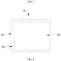
- the first spring 25 and the second spring 29 are of the same size and each sheathed within a support sleeve 26.
- a third through hole 261 with a diameter matching with the diameter of the limiting member 201 is disposed at an end of the support sleeve 26, such that the limiting member 201 can be moved into the support sleeve 26 through the third through hole 261.
- An abutting ring 262 is provided at the other end of the support sleeve 26 for abutting against the end of the first spring 25 or the second spring 29.
- a fourth through hole 263 is disposed at a center of the abutting ring 262. A diameter of the fourth through hole 263 matches with the diameter of the connecting rod 20 such that the end of the connecting rod 20 can pass through the fourth through hole 263.
- the end of the support sleeve 26 with the abutting ring 262 abuts against the second connecting plate 28.
- the connecting rod 20 successively passes through the limiting hole 223, the second through hole 282, the third through hole 261, and the second spring 29, the end of the connecting rod 20 is fixedly connected to a limiting cap 27.
- a diameter of the limiting cap 27 matches with a diameter of the third through hole 261 of the support sleeve 26 such that the limiting cap 27 can be moved into the support sleeve 26.
- One end of the second spring 29 abuts against the abutting ring 262, and the other end of the second spring 29 abuts against the limiting cap 27.
- the diameter of the first through hole 212 of the first connecting plate 21 is greater than an outer diameter of the support sleeve 26, such that the support sleeve 26 can pass through the first through hole 212.
- the end of the support sleeve 26 with the third through hole 261 passes through the first through hole 212 of the first connecting plate 21 and abuts against the rotation control plate 22.
- the connecting rod 20 successively passes through the limiting hole 223 of the rotation control plate 22, the first through hole 212 of the first connecting plate 21, the first spring 25, and the fourth through hole 263 of the support sleeve 26.
- the limiting member 201 successively passes through the limiting hole 223 and the first through hole 212 to abut against one end of the first spring 25, and the other end of the first spring 25 abuts against the abutting ring 262 at an inner side of the support sleeve 26.
- the end of the connecting rod 20, after passing through the support sleeve 26, is fixedly connected to an eccentric cam handle 24.
- the eccentric cam handle 24 is an eccentric cam operation handle, as shown in FIGs. 5 and 6 .
- a length of the connecting rod 20 that is pulled outwards can be adjusted, and the limiting member 201 can be moved out of the limiting hole 223, thereby enabling control of rotation-locked and rotation-unlocked states of the armrest handle 1 by the eccentric cam handle 24.
- the right limiting member 201 on the connecting rod 20 is positioned in the right limiting hole 223 when the eccentric cam handle 24 is rotated to the closed state, and the right limiting member 201 on the connecting rod 20 is moved out of the right limiting hole 223 when the eccentric cam handle 24 is rotated to the open state.
- the support sleeve 26 can also abut against the surface of the first connecting plate 21, such that the limiting member 201 can be moved into the support sleeve 26 through the limiting hole 223, the first through hole 212, and the third through hole 261, so as to abut against the first spring 25.
- the length of the support sleeve 26 or the length of the first spring 25 at this side may be further adjusted, such that the two ends of the connecting rod 20 are moved by the same amount, thereby enabling the limiting members 201 at the two ends of the connecting rod 20 to be synchronously moved out of corresponding limiting holes 223, which will not be described in detail in this embodiment.
- fourth mounting holes 101 are first disposed separately at symmetrical positions on treadmill frame tubes 100 at two sides of the treadmill.
- a fastener 23 successively passes through the through hole at the left bottom end of the armrest handle 1, the first mounting hole 211 of the first connecting plate 21, the second mounting hole 221 of the rotation control plate 22, and the left fourth mounting hole 101 on the treadmill so as to engage the left lower end of the armrest handle 1, the first connecting plate 21, and the rotation control plate 22 to the left treadmill frame tube 100 of the treadmill.
- a fastener 23 successively passes through the through hole at the right bottom end of the armrest handle 1, the third mounting hole 281 of the second connecting plate 28, the second mounting hole 221 of the rotation control plate 22, and the right fourth mounting hole 101 on the treadmill so as to engage the right bottom end of the armrest handle 1, the second connecting plate 28, and the rotation control plate 22 to the right treadmill frame tube 100 of the treadmill.
- the connecting rod 20 enters the left side of the armrest handle 1, successively passes through the first through hole 212 of the first connecting plate 21 and the limiting hole 223 of the rotation control plate 22, and then successively passes through the limiting hole 223 of the right rotation control plate 22 and the second through hole 282 of the second connecting plate 28, such that the end of the limiting member 201 at the right end of the connecting rod 20 abuts against the second connecting plate 28.
- the second spring 29, the support sleeve 26, and the limiting cap 27 at the right side of the armrest handle 1 are fixedly connected, and then the first spring 25, the support sleeve 26, and the eccentric cam handle 24 at the left side of the armrest handle 1 are fixedly mounted, thus completing mounting.
- the combination of the rotation control plate 22 with the limiting member 201 may be provided only at one side of the armrest handle, which may also achieve the rotation control of the armrest handle 1.
- the connecting rod 20 is provided with a limiting member 201 only on the left side, and a rotation control plate 22 is provided at the left end of the armrest handle 1.
- this embodiment requires reduced component parts and material costs, and achieves simplification in mounting.
- the folding mechanism for an armrest handle of a treadmill of the present invention enables the armrest handle to be folded through an operation at one side of the treadmill, so as to achieve an easy operation, a simple structure, and convenience in mounting.
Landscapes
- Health & Medical Sciences (AREA)
- General Health & Medical Sciences (AREA)
- Physical Education & Sports Medicine (AREA)
- Cardiology (AREA)
- Vascular Medicine (AREA)
- Life Sciences & Earth Sciences (AREA)
- Biophysics (AREA)
- Orthopedic Medicine & Surgery (AREA)
- Rehabilitation Tools (AREA)
Applications Claiming Priority (1)
| Application Number | Priority Date | Filing Date | Title |
|---|---|---|---|
| CN202322078544.7U CN220632898U (zh) | 2023-08-03 | 2023-08-03 | 跑步机扶手杆折叠机构 |
Publications (3)
| Publication Number | Publication Date |
|---|---|
| EP4353333A1 true EP4353333A1 (de) | 2024-04-17 |
| EP4353333B1 EP4353333B1 (de) | 2025-04-30 |
| EP4353333C0 EP4353333C0 (de) | 2025-04-30 |
Family
ID=87762455
Family Applications (1)
| Application Number | Title | Priority Date | Filing Date |
|---|---|---|---|
| EP23192853.2A Active EP4353333B1 (de) | 2023-08-03 | 2023-08-23 | Klappmechanismus für armlehnengriff eines laufbands |
Country Status (7)
| Country | Link |
|---|---|
| US (1) | US12370401B2 (de) |
| EP (1) | EP4353333B1 (de) |
| JP (1) | JP3244313U (de) |
| KR (1) | KR20250020250A (de) |
| CN (1) | CN220632898U (de) |
| ES (1) | ES3031422T3 (de) |
| PL (1) | PL4353333T3 (de) |
Families Citing this family (2)
| Publication number | Priority date | Publication date | Assignee | Title |
|---|---|---|---|---|
| CN115804931B (zh) * | 2022-12-27 | 2025-11-04 | 三羚(厦门)运动科技工业有限公司 | 一种实现跑台收折与坡度抬升的跑步机架 |
| CN221788036U (zh) * | 2023-12-15 | 2024-10-01 | 江西伊启实业有限公司 | 跑步机扶手折叠结构 |
Citations (4)
| Publication number | Priority date | Publication date | Assignee | Title |
|---|---|---|---|---|
| US20130237381A1 (en) * | 2012-03-06 | 2013-09-12 | Ming-Nan Chen | Collapsible mechanism for treadmill |
| EP3679991A1 (de) * | 2019-01-09 | 2020-07-15 | OMA Fitness Equipment Co., Ltd. | Elektrisches laufband |
| CN111388951B (zh) * | 2020-03-23 | 2021-08-27 | 成都清妙创意设计有限公司 | 一种便携式跑步机 |
| CN218485084U (zh) * | 2022-08-16 | 2023-02-17 | 杭州如泽电子商务有限公司 | 一种跑步机折叠机构 |
Family Cites Families (11)
| Publication number | Priority date | Publication date | Assignee | Title |
|---|---|---|---|---|
| TW566177U (en) | 2003-03-17 | 2003-12-11 | Huang-Dung Jang | Improved folding and power-saving structure for device for jogging treadmill |
| US7540829B1 (en) * | 2008-04-17 | 2009-06-02 | Michael Lin | Foldable mechanism for treadmills |
| US7637850B2 (en) * | 2008-05-12 | 2009-12-29 | Michael Lin | Treadmill having adjustable control panel |
| US7942788B2 (en) | 2009-07-27 | 2011-05-17 | Strength Master Fitness Tech. Co., Ltd. | Foldable treadmill |
| CN210644982U (zh) | 2019-08-19 | 2020-06-02 | 厦门帝玛斯健康科技有限公司 | 一种可折叠的跑步机 |
| CN211301913U (zh) * | 2019-10-29 | 2020-08-21 | 顶康科技有限公司 | 跑步机的立柱折叠机构 |
| CN110860063B (zh) * | 2019-10-29 | 2024-09-20 | 顶康科技有限公司 | 一种跑步机的立柱折叠机构 |
| CN111672060B (zh) * | 2020-06-24 | 2022-09-27 | 江西伊启实业有限公司 | 一种折叠跑步机及折叠方法 |
| CN113996007B (zh) | 2021-11-02 | 2022-10-18 | 江西伊启实业有限公司 | 一种跑步机 |
| CN216497270U (zh) * | 2021-12-13 | 2022-05-13 | 北京小米移动软件有限公司 | 运动设备 |
| DE202022106891U1 (de) * | 2022-12-08 | 2023-03-12 | Metotrade | Eine neue Art von Laufband |
-
2023
- 2023-08-03 CN CN202322078544.7U patent/CN220632898U/zh active Active
- 2023-08-23 PL PL23192853.2T patent/PL4353333T3/pl unknown
- 2023-08-23 ES ES23192853T patent/ES3031422T3/es active Active
- 2023-08-23 EP EP23192853.2A patent/EP4353333B1/de active Active
- 2023-08-23 US US18/454,453 patent/US12370401B2/en active Active
- 2023-08-24 KR KR1020230111601A patent/KR20250020250A/ko active Pending
- 2023-08-28 JP JP2023003109U patent/JP3244313U/ja active Active
Patent Citations (4)
| Publication number | Priority date | Publication date | Assignee | Title |
|---|---|---|---|---|
| US20130237381A1 (en) * | 2012-03-06 | 2013-09-12 | Ming-Nan Chen | Collapsible mechanism for treadmill |
| EP3679991A1 (de) * | 2019-01-09 | 2020-07-15 | OMA Fitness Equipment Co., Ltd. | Elektrisches laufband |
| CN111388951B (zh) * | 2020-03-23 | 2021-08-27 | 成都清妙创意设计有限公司 | 一种便携式跑步机 |
| CN218485084U (zh) * | 2022-08-16 | 2023-02-17 | 杭州如泽电子商务有限公司 | 一种跑步机折叠机构 |
Also Published As
| Publication number | Publication date |
|---|---|
| US20250041655A1 (en) | 2025-02-06 |
| PL4353333T3 (pl) | 2025-06-23 |
| ES3031422T3 (en) | 2025-07-08 |
| JP3244313U (ja) | 2023-10-25 |
| KR20250020250A (ko) | 2025-02-11 |
| US12370401B2 (en) | 2025-07-29 |
| EP4353333B1 (de) | 2025-04-30 |
| EP4353333C0 (de) | 2025-04-30 |
| CN220632898U (zh) | 2024-03-22 |
Similar Documents
| Publication | Publication Date | Title |
|---|---|---|
| EP4353333A1 (de) | Klappmechanismus für armlehnengriff eines laufbands | |
| US11291297B2 (en) | Portable and adjustable picnic table | |
| US11006755B2 (en) | Rocking chair | |
| US8313139B2 (en) | Portable table assemblies | |
| US7448581B2 (en) | Display apparatus | |
| US11241087B2 (en) | Adjustment mechanism and structure having same | |
| US7066438B2 (en) | Collapsible supporting device for a portable computer | |
| US6053851A (en) | Body exerciser | |
| CN210611640U (zh) | 一种折叠床架和折叠床 | |
| CN109043820A (zh) | 一种信息技术教学装置 | |
| AU2018100562A4 (en) | Collapsible grill | |
| EP4635580A1 (de) | Zusammenklappbarer hantelständer | |
| CN207644495U (zh) | 扶手结构及具有其的车辆 | |
| CN212698122U (zh) | 一种视频会议桌 | |
| CN211525892U (zh) | 脚架结构和自拍装置 | |
| US20250283378A1 (en) | Ladder with lifting and lowering handrail | |
| US10688011B1 (en) | Foldable walker | |
| US6871912B1 (en) | Highchair | |
| CN108890332A (zh) | 一种用于机械加工的自动夹具 | |
| CN208926828U (zh) | 一种铲式担架 | |
| CN221243883U (zh) | 一种可用于轮椅的手臂训练装置 | |
| CN223516436U (zh) | 一种具有升降调节角度功能的多用器械支撑架 | |
| US20260047681A1 (en) | Director chair | |
| CN220558479U (zh) | 一种可折叠跑步机 | |
| LU506802B1 (en) | Portable folding medical first-aid case |
Legal Events
| Date | Code | Title | Description |
|---|---|---|---|
| PUAI | Public reference made under article 153(3) epc to a published international application that has entered the european phase |
Free format text: ORIGINAL CODE: 0009012 |
|
| STAA | Information on the status of an ep patent application or granted ep patent |
Free format text: STATUS: REQUEST FOR EXAMINATION WAS MADE |
|
| 17P | Request for examination filed |
Effective date: 20230823 |
|
| AK | Designated contracting states |
Kind code of ref document: A1 Designated state(s): AL AT BE BG CH CY CZ DE DK EE ES FI FR GB GR HR HU IE IS IT LI LT LU LV MC ME MK MT NL NO PL PT RO RS SE SI SK SM TR |
|
| GRAP | Despatch of communication of intention to grant a patent |
Free format text: ORIGINAL CODE: EPIDOSNIGR1 |
|
| STAA | Information on the status of an ep patent application or granted ep patent |
Free format text: STATUS: GRANT OF PATENT IS INTENDED |
|
| INTG | Intention to grant announced |
Effective date: 20250217 |
|
| GRAS | Grant fee paid |
Free format text: ORIGINAL CODE: EPIDOSNIGR3 |
|
| GRAA | (expected) grant |
Free format text: ORIGINAL CODE: 0009210 |
|
| STAA | Information on the status of an ep patent application or granted ep patent |
Free format text: STATUS: THE PATENT HAS BEEN GRANTED |
|
| AK | Designated contracting states |
Kind code of ref document: B1 Designated state(s): AL AT BE BG CH CY CZ DE DK EE ES FI FR GB GR HR HU IE IS IT LI LT LU LV MC ME MK MT NL NO PL PT RO RS SE SI SK SM TR |
|
| REG | Reference to a national code |
Ref country code: CH Ref legal event code: EP Ref country code: GB Ref legal event code: FG4D |
|
| REG | Reference to a national code |
Ref country code: DE Ref legal event code: R096 Ref document number: 602023003175 Country of ref document: DE |
|
| REG | Reference to a national code |
Ref country code: IE Ref legal event code: FG4D |
|
| U01 | Request for unitary effect filed |
Effective date: 20250528 |
|
| REG | Reference to a national code |
Ref country code: ES Ref legal event code: FG2A Ref document number: 3031422 Country of ref document: ES Kind code of ref document: T3 Effective date: 20250708 |
|
| U07 | Unitary effect registered |
Designated state(s): AT BE BG DE DK EE FI FR IT LT LU LV MT NL PT RO SE SI Effective date: 20250605 |
|
| PGFP | Annual fee paid to national office [announced via postgrant information from national office to epo] |
Ref country code: CZ Payment date: 20250625 Year of fee payment: 3 |
|
| U20 | Renewal fee for the european patent with unitary effect paid |
Year of fee payment: 3 Effective date: 20250625 |
|
| PG25 | Lapsed in a contracting state [announced via postgrant information from national office to epo] |
Ref country code: NO Free format text: LAPSE BECAUSE OF FAILURE TO SUBMIT A TRANSLATION OF THE DESCRIPTION OR TO PAY THE FEE WITHIN THE PRESCRIBED TIME-LIMIT Effective date: 20250730 Ref country code: GR Free format text: LAPSE BECAUSE OF FAILURE TO SUBMIT A TRANSLATION OF THE DESCRIPTION OR TO PAY THE FEE WITHIN THE PRESCRIBED TIME-LIMIT Effective date: 20250731 |
|
| PGFP | Annual fee paid to national office [announced via postgrant information from national office to epo] |
Ref country code: PL Payment date: 20250702 Year of fee payment: 3 |
|
| PG25 | Lapsed in a contracting state [announced via postgrant information from national office to epo] |
Ref country code: HR Free format text: LAPSE BECAUSE OF FAILURE TO SUBMIT A TRANSLATION OF THE DESCRIPTION OR TO PAY THE FEE WITHIN THE PRESCRIBED TIME-LIMIT Effective date: 20250430 |
|
| PG25 | Lapsed in a contracting state [announced via postgrant information from national office to epo] |
Ref country code: RS Free format text: LAPSE BECAUSE OF FAILURE TO SUBMIT A TRANSLATION OF THE DESCRIPTION OR TO PAY THE FEE WITHIN THE PRESCRIBED TIME-LIMIT Effective date: 20250731 |
|
| PG25 | Lapsed in a contracting state [announced via postgrant information from national office to epo] |
Ref country code: IS Free format text: LAPSE BECAUSE OF FAILURE TO SUBMIT A TRANSLATION OF THE DESCRIPTION OR TO PAY THE FEE WITHIN THE PRESCRIBED TIME-LIMIT Effective date: 20250830 |
|
| PG25 | Lapsed in a contracting state [announced via postgrant information from national office to epo] |
Ref country code: SM Free format text: LAPSE BECAUSE OF FAILURE TO SUBMIT A TRANSLATION OF THE DESCRIPTION OR TO PAY THE FEE WITHIN THE PRESCRIBED TIME-LIMIT Effective date: 20250430 |
|
| PG25 | Lapsed in a contracting state [announced via postgrant information from national office to epo] |
Ref country code: SK Free format text: LAPSE BECAUSE OF FAILURE TO SUBMIT A TRANSLATION OF THE DESCRIPTION OR TO PAY THE FEE WITHIN THE PRESCRIBED TIME-LIMIT Effective date: 20250430 |
|
| PGFP | Annual fee paid to national office [announced via postgrant information from national office to epo] |
Ref country code: ES Payment date: 20251009 Year of fee payment: 3 |