EP3679991A1 - Elektrisches laufband - Google Patents
Elektrisches laufband Download PDFInfo
- Publication number
- EP3679991A1 EP3679991A1 EP19165529.9A EP19165529A EP3679991A1 EP 3679991 A1 EP3679991 A1 EP 3679991A1 EP 19165529 A EP19165529 A EP 19165529A EP 3679991 A1 EP3679991 A1 EP 3679991A1
- Authority
- EP
- European Patent Office
- Prior art keywords
- connecting member
- armrest
- hinge tooth
- tube
- base
- Prior art date
- Legal status (The legal status is an assumption and is not a legal conclusion. Google has not performed a legal analysis and makes no representation as to the accuracy of the status listed.)
- Withdrawn
Links
- 125000006850 spacer group Chemical group 0.000 claims description 3
- 230000004048 modification Effects 0.000 description 2
- 238000012986 modification Methods 0.000 description 2
- 230000009286 beneficial effect Effects 0.000 description 1
- 230000003993 interaction Effects 0.000 description 1
- 238000005457 optimization Methods 0.000 description 1
Images


Classifications
-
- A—HUMAN NECESSITIES
- A63—SPORTS; GAMES; AMUSEMENTS
- A63B—APPARATUS FOR PHYSICAL TRAINING, GYMNASTICS, SWIMMING, CLIMBING, OR FENCING; BALL GAMES; TRAINING EQUIPMENT
- A63B22/00—Exercising apparatus specially adapted for conditioning the cardio-vascular system, for training agility or co-ordination of movements
- A63B22/02—Exercising apparatus specially adapted for conditioning the cardio-vascular system, for training agility or co-ordination of movements with movable endless bands, e.g. treadmills
- A63B22/0235—Exercising apparatus specially adapted for conditioning the cardio-vascular system, for training agility or co-ordination of movements with movable endless bands, e.g. treadmills driven by a motor
- A63B22/0242—Exercising apparatus specially adapted for conditioning the cardio-vascular system, for training agility or co-ordination of movements with movable endless bands, e.g. treadmills driven by a motor with speed variation
- A63B22/025—Exercising apparatus specially adapted for conditioning the cardio-vascular system, for training agility or co-ordination of movements with movable endless bands, e.g. treadmills driven by a motor with speed variation electrically, e.g. D.C. motors with variable speed control
-
- A—HUMAN NECESSITIES
- A63—SPORTS; GAMES; AMUSEMENTS
- A63B—APPARATUS FOR PHYSICAL TRAINING, GYMNASTICS, SWIMMING, CLIMBING, OR FENCING; BALL GAMES; TRAINING EQUIPMENT
- A63B22/00—Exercising apparatus specially adapted for conditioning the cardio-vascular system, for training agility or co-ordination of movements
- A63B22/02—Exercising apparatus specially adapted for conditioning the cardio-vascular system, for training agility or co-ordination of movements with movable endless bands, e.g. treadmills
- A63B22/0235—Exercising apparatus specially adapted for conditioning the cardio-vascular system, for training agility or co-ordination of movements with movable endless bands, e.g. treadmills driven by a motor
-
- A—HUMAN NECESSITIES
- A63—SPORTS; GAMES; AMUSEMENTS
- A63B—APPARATUS FOR PHYSICAL TRAINING, GYMNASTICS, SWIMMING, CLIMBING, OR FENCING; BALL GAMES; TRAINING EQUIPMENT
- A63B22/00—Exercising apparatus specially adapted for conditioning the cardio-vascular system, for training agility or co-ordination of movements
- A63B22/0046—Details of the support elements or their connection to the exercising apparatus, e.g. adjustment of size or orientation
-
- A—HUMAN NECESSITIES
- A63—SPORTS; GAMES; AMUSEMENTS
- A63B—APPARATUS FOR PHYSICAL TRAINING, GYMNASTICS, SWIMMING, CLIMBING, OR FENCING; BALL GAMES; TRAINING EQUIPMENT
- A63B22/00—Exercising apparatus specially adapted for conditioning the cardio-vascular system, for training agility or co-ordination of movements
- A63B22/02—Exercising apparatus specially adapted for conditioning the cardio-vascular system, for training agility or co-ordination of movements with movable endless bands, e.g. treadmills
- A63B22/0235—Exercising apparatus specially adapted for conditioning the cardio-vascular system, for training agility or co-ordination of movements with movable endless bands, e.g. treadmills driven by a motor
- A63B22/0242—Exercising apparatus specially adapted for conditioning the cardio-vascular system, for training agility or co-ordination of movements with movable endless bands, e.g. treadmills driven by a motor with speed variation
- A63B22/0257—Mechanical systems therefor
-
- A—HUMAN NECESSITIES
- A63—SPORTS; GAMES; AMUSEMENTS
- A63B—APPARATUS FOR PHYSICAL TRAINING, GYMNASTICS, SWIMMING, CLIMBING, OR FENCING; BALL GAMES; TRAINING EQUIPMENT
- A63B2210/00—Space saving
- A63B2210/50—Size reducing arrangements for stowing or transport
Definitions
- the disclosure relates to the technical field of fitness instrument, in particular to an electric treadmill.
- the treadmill is common fitness equipment used at home and gyms, which is the simple one and the optimization of household fitness instruments.
- the treadmill includes a base supporting a user to run or walk thereon, and an armrest equipped with various electronic components to control the treadmill and to provide interactions.
- a length of the base needs to be larger than a stride length of the user.
- the length of the base ranges from 1.5 to 2 meters.
- the longer the length of the base the wider a width of the base. Therefore, the treadmill may take up more spaces.
- Embodiments of the present disclosure provide an electric treadmill to solve or alleviate one or more technical problems in the prior art, or at least provide an advantageous selection.
- an electric treadmill which includes:
- the connecting assembly includes a first connecting member, a second connecting member, two third connecting members, and a fourth connecting member, wherein one end of the first connecting member is connected to the front frame and the other end of the first connecting member is hinged with one end of each third connecting member; a middle portion of the second connecting member is hinged with a middle portion of each third connecting member; and one end of the fourth connecting member is hinged with one end of the second connecting member, and the other end of the fourth connecting member is connected to the rear frame.
- the first connecting member includes a head portion and a bottom portion; the head portion protrudes from an intermediate position of the bottom portion to form a a T shaped first connecting member; a first through hole is provided at one end of the bottom portion away from the head portion, to hinge the first connecting member with the base; a second through hole is provided at the head portion to hinge the first connecting member with each third connecting member, and a side of the bottom portion facing the second connecting member is provided with a first curved slot; wherein the second connecting member includes a front portion and a rear portion disposed at a predetermined angle with the front portion, one end of the front portion away from the rear portion is provided with a first curved surface corresponding to the first curved slot, a middle portion of the second connecting member is hinged with a middle portion of each third connecting member, and one end of the rear portion away from the front portion is hinged with the one end of the fourth connecting member; wherein the one end of each third connecting member is hinged with the head portion, the other end of each third connecting member is
- the connecting assembly includes a front mount, a rear mount, a first hinge tooth, a second hinge tooth, a third hinge tooth and a fourth hinge tooth;
- the first hinge tooth, the second hinge tooth, the third hinge tooth, and the fourth hinge tooth are all L-shaped with a short portion and a long portion;
- the front mount is fastened to the front frame and the rear mount is fastened to the rear frame;
- a joint between the short portion and the long portion of the first hinge tooth, a joint between the short portion and the long portion of the second hinge tooth, a joint of the short portion and the long portion of the third hinge tooth, and a joint between the short portion and the long portion of the fourth hinge tooth are hinged together by a first rotating shaft;
- front ends of the long portions of the first hinge tooth and the second hinge tooth are hinged together by a second rotating shaft;
- rear ends of the long portions of the third hinge tooth and the fourth hinge tooth are hinged together by a third rotating shaft;
- the third hinge tooth is disposed between the first hinge tooth and
- the vertical tube includes a hollow tube, an armrest tube, and a controllable gas spring, wherein the armrest tube is disposed in the hollow tube, one end of the controllable gas spring is connected to the armrest tube, and the other end of the controllable gas spring is connected to the hollow tube, and the armrest tube is telescoped relative to the hollow tube to adjust a length of the armrest.
- the electric treadmill further includes a side rest detachably connected with the armrest, and a connecting portion provided on the armrest tube, corresponding to the side rest; wherein the side rest comprises a main body; a tab is provided at an end of the main body; a slot is provided on the connecting portion; and the tab is inserted into the slot to connect the main body to the connecting portion.
- the electric treadmill further includes a spring provided at the end of the main body, and a ball connected to the spring; wherein the ball is abutted against the connecting portion by a force of the spring.
- the electric treadmill further includes a locking assembly, wherein the locking assembly includes a quick release lever, a pressing block, a positioning sleeve, a spring, and a spacer; the positioning sleeve is disposed at the joint between the hollow tube and the armrest tube; the quick release lever is hinged with the positioning sleeve, and the pressing block is disposed between the quick release lever and the positioning sleeve; and one end of the quick release lever connected to the positioning sleeve is provided with a cam structure so as to press the quick release lever against the pressing block to lock the armrest tube.
- the locking assembly includes a quick release lever, a pressing block, a positioning sleeve, a spring, and a spacer; the positioning sleeve is disposed at the joint between the hollow tube and the armrest tube; the quick release lever is hinged with the positioning sleeve, and the pressing block is disposed between the quick release lever and the positioning sleeve; and one end of the quick release lever connected
- the electric treadmill further includes a depressurizing lever, wherein one end of the depressurizing lever is connected to the armrest, and the other end of the depressurizing lever is connected to the base to slow down a speed of the armrest rotating toward the base.
- one end of the depressurizing lever is connected to the hollow tube, and the other end of the depressurizing lever is connected to the front frame, both ends of which are fastened by bolts and fasteners.
- the electric treadmill further includes a torsional spring, wherein one end of the torsional spring is connected to the vertical tube, and the other end of the torsional spring is connected to the front frame, to slow down a rotating speed of the vertical tube toward the front frame.
- an angle retaining plate, a stopper plate and a locking handle are provided at a joint between the vertical tube and the base, the angle retaining plate is provided with a curved retaining slot, and a retaining shaft corresponding to the curved retaining slot is provided at the base to cooperate with the angle retaining plate, so as to limit a rotating angle of the armrest, and wherein one end of the locking handle is provided with a cam structure so that the locking handle enables to limit a rotation of the vertical tube relative to the base, and the armrest is foldable over the base by pulling the locking handle and rotating the armrest for storage.
- an angle between the front frame and the rear frame varies between 0 and 180 degrees
- the tread board comprises a front tread board and a rear tread board, the front tread board is provided in the front frame and the rear tread board is provided in the rear frame; and the front tread board and the rear tread board are combined to support the user in case of the angle between the front frame and the rear frame being 180 degrees.
- the armrest comprises a plurality of vertical tubes disposed on two sides of the front frame respectively, the vertical tubes are connected with the cross tube to form a storage space for accommodating the base, and the front frame and the rear frame is accommodated in the storage space in case of the angle between the front frame and the rear frame being 0 degree.
- the front frame and the rear frame in the present disclosure may be folded with respect to each other, thus, reducing a length of the base for storage and improving the experience of users.
- the present disclosure provides an electric treadmill.
- the electric treadmill includes a base 10 and an armrest 20.
- the base 10 is provided with a drive motor, a drum, a running belt and other components, while the armrest 20 is provided with an operation switch and other control components.
- the base 10 presents a shape of a rectangular plate, and includes a front frame 11, a rear frame 12, and a connecting assembly 30, wherein tread boards 13 are provided within the front frame 11 and the rear frame 12.
- the front frame 11 and the rear frame 12 are hinged together by the connecting assembly 30 in order to fold the base 10 for storage.
- the connection between the front frame 11 and the rear frame 12 is not limited thereto, and the connection capable of folding and accommodating the base 10 may be applied thereto
- the armrest 20 includes a vertical tube 21 and a cross tube 22. One end of the vertical tube 21 is connected to the cross tube 22, and the other end of the vertical tube 21 is rotatably coupled to the base 10 to allow the armrest 20 to be folded with respect to the base 10. As shown in Fig. 3 , the front frame 11 and the rear frame 12 may be foldable with respect to each other. The armrest 20 and the base 10 may also be foldable with respect to each other. A length of the base 10 is greatly reduced for storage, thus, improving the experience of users.
- the connecting assembly 30 includes a first connecting member 31, a second connecting member 32, two third connecting members 33, and a fourth connecting member 34, wherein the second connecting member 32 is disposed between the two third connecting members 33.
- One end of the first connecting member 31 is hinged with the front frame 11, and the other end of the first connecting member 31 is hinged with one end of each third connecting member 33.
- the middle portion of the second connecting member 32 is hinged with the middle portion of each third connecting members 33.
- One end of the fourth connecting member 34 is hinged with one end of each second connecting member 32, and the other end of the fourth connecting member 34 is hinged with the rear frame 12.
- the first connecting member 31 includes a head portion 311 and a bottom portion 312.
- the head portion 311 protrudes from an intermediate position of the bottom portion 312 to form a T shaped first connecting member 31.
- a first through hole 71 is provided at one end of the bottom portion 312 away from the head portion 311, to hinge the first connecting member 31 with the base 10 by a rotating shaft 70.
- a second through hole 71 is provided at head portion 311 to hinge he first connecting member 31 with the third connecting members 33.
- a side of the bottom portion 312 facing the second connecting member 32 is provided with a first curved slot 313.
- the second connecting member 32 includes a front portion 321; and a rear portion 322 disposed at a predetermined angle with the front portion 321.
- One end of the front portion 321 away from the rear portion 322 is provided with a first curved surface 323 corresponding to the first curved slot 313.
- the middle portion of the second connecting member 32 that is, a joint between the front portion 321 and the rear portion 322, is hinged with the middle portion of each third connecting member 33.
- One end of the rear portion 322 away from the front portion 321 is hinged with the one end of the fourth connecting member 34.
- One end of the fourth connecting member 34 is hinged with the rear portion 322, and the other end of the fourth connecting member 34 is hinged with the rear frame 12.
- a second curved surface 341 facing the third connecting members 33 is provided with on the fourth connecting member 34, wherein the second curved surface 341 is fitted to the arcuate protrusion 331.
- the front frame and the rear frame When the front frame and the rear frame are in a folded state, that is, the front frame and the rear frame are at an angle of 0 degree as shown in Fig. 3 , the first curved surface 323 abuts the first curved slot 313 and the arcuate protrusion 331 abuts the second curved surface 341.
- the front frame and the rear frame When the front frame and the rear frame are in an unfolded state, that is, the front frame and the rear frame are at an angle of 180 degrees, the rear frame rotates relative to the front frame to separate the first curved surface 323 from the first curved slot 313, and separate the circular arcuate protrusion 331 from the second curved surface 341.
- the connecting assembly 30' includes a front mount 35, a rear mount 36, a first hinge tooth 371, a second hinge tooth 372, a third hinge tooth 373, a fourth hinge tooth 374, and a rotating shaft 90.
- the first hinge tooth 371, the second hinge tooth 372, the third hinge tooth 373, and the fourth hinge tooth 374 are all L-shaped with a short portion 375 and a long portion 376.
- a joint between the short portion 375 and the long portion 376 of the first hinge tooth 371, a joint between the short portion 375 and the long portion 376 of the second hinge tooth 372, a joint between the short portion 375 and the long portion 376 of the third hinge tooth 373 and a joint between the short portion 375 and the long portion 376 of the fourth hinge tooth 374 are hinged together by a first rotating shaft 90. Front ends of the long portions 376 of the first hinge tooth 371 and the second hinge tooth 372 are hinged together by a second rotating shaft 90. Rear ends of the long portions 376 of the third hinge tooth 373 and the fourth hinge tooth 374 are hinged together by a third rotating shaft 90.
- the third hinge tooth 373 is disposed between the first hinge tooth 371 and the second hinge tooth 372, and the second hinge tooth 372 is disposed between the third hinge tooth 373 and the fourth hinge tooth 374.
- the front mount 35 is provided with a front relief groove 351 for accommodating the first hinge tooth 371 and the second hinge tooth 372. Also, the front mount 35 is also provided with a front chute 352 extending in a front-rear direction.
- the rear mount 36 is provided with a rear relief groove 361 for accommodating the third hinge tooth 373 and the fourth hinge tooth 374. Also, the rear mount 36 is also provided with a rear chute 362 extending in the front-rear direction.
- the second rotating shaft 90 is slidably coupled to the front chute 352.
- the third rotating shaft 90 is slidably coupled to the rear chute 362.
- a front abutting surface 354 of the front mount 35 and a rear abutting surface 364 of the rear mount 36 changes from a state of being in contact with each other to a state of being at 180 degrees therebetween, the front abutting surface 354 and the rear abutting surface 364 form an angle with respect to each other.
- the first hinge tooth 371, the second hinge tooth 372, the third hinge tooth 373 and the fourth hinge tooth 374 rotate around the first rotating shaft 90, so that the second rotating shaft 90 may slide in the front chute 352 from front to rear, and the third rotating shaft 90 may slide in the rear chute 362 from rear to front.
- the front mount 35 and the rear mount 36 may be completely unfolded.
- the second rotating shaft 90 remains at the rear end of the front chute 352
- the third rotating shaft 90 remains at the front end of the rear chute 362.
- the front mount 35 and the rear mount 36 are folded, that is, the front abutting surface 354 and the rear abutting surface 364 changes from the state of being at 180 degrees to the state of being in contact with each other, the rear frame 12 rotates relative to the front frame 11.
- the rear mount 36 pushes the third rotating shaft 90 such that the second rotating shaft 90 may slide in the front chute 352 from rear to front.
- the front mount 35 pushes the second rotating shaft 90, so that the second rotating shaft 90 may slide in the rear chute 362 from front to rear.
- the front mount 35 and the rear mount 36 may be completely folded.
- the front abutting surface 354 and the rear abutting surface 364 are in contact with each other.
- the electric treadmill further includes a locking assembly 40 for locking and fastening the armrest tube 212, which specifically includes a quick release lever 41, a pressing block 42, a positioning sleeve 43, a spring 44 and the spacer 45.
- the positioning sleeve 43 is disposed at the joint between the hollow tube 211 and the armrest tube 212.
- the quick release lever 41 is hinged with the positioning sleeve 43, and the pressing block 42 is disposed between the quick release lever 41 and the positioning sleeve 43.
- a cam structure is provided at one end of the quick release lever 41 connected to the positioning sleeve 43, so as to press the quick release lever 41 against the pressing block 42 to lock the armrest tube 212.
- a side rest 214 is detachably is connected to the armrest tube 212.
- a connecting portion 216 corresponding to the side rest 214 is provided on the armrest tube 212.
- the side rest 214 includes a main body 215 with a tab 217 at an end.
- a slot 218 is provided on the connecting portion 216. Referring to Fig. 16 , the tab 217 may slide along a direction from up to down and insert into the slot 218, so that the main body 215 may be connected to the connecting portion 216.
- a spring 219 is provided at the end of main body 215.
- One end of the spring 219 is connected to the main body 215, and a ball 220 is provided at the other end of the spring 219.
- the ball 220 may contact a surface 221 of the connecting portion 216.
- the surface 221 may apply a force to ball 220 so as to compress the spring 219.
- the spring 219 may react a force on the ball 220 and the surface 221 to abut the ball 220 against the surface 221, thus fastening the tab 217 into the slot 218.
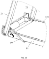
- the electric treadmill further includes a depressurizing lever 50.
- One end of the depressurizing lever 50 is connected to the armrest 20, and the other end of the depressurizing lever 50 is connected to the base 10, so as to slow down a speed of the armrest 20 rotating toward the base 10.
- one end of the depressurizing lever 50 is connected to the hollow tube 211, and the other end of the depressurizing lever 50 is connected to the front frame 11. Both ends of the depressurizing lever are fastened by bolts and fasteners.
- an angle retaining plate 23, a stopper plate 24 and a locking handle 25 are provided at a joint between the armrest 20 and the base 10.
- the angle retaining plate 23 is provided with a curved retaining slot 231.
- a retaining shaft 14 corresponding to the curved retaining slot 231 is provided at the base 10.
- the retaining shaft 14 and the angle retaining plate 23 cooperate to limit a rotating angle of the armrest 20.
- One end of the locking handle 25 is provided with a cam structure so that the locking handle 25 may limit a rotation of the armrest 20 relative to the base 10.
- the armrest 20 When being folded for storage, the armrest 20 may be folded over the base 10 by pulling the locking handle 25 and rotating the armrest 20, and it is very easy and convenient to operate.
- an angle between the front frame 11 and the rear frame 12 varies between 0 and 180 degrees.
- the tread board 13 comprises a front tread board 131 and a rear tread board 132.
- the front tread board 131 is provided in the front frame 11, and the rear tread board 132 is provided in the rear frame 12.
- the front tread board 131 and the rear tread board 132 are combined to support the user.
- the front tread board 131 and the rear tread board 132 are folded for storage.
- the armrest 20 includes a plurality of vertical tubes 21 disposed on two sides of the front frame 11 respectively.
- the vertical tube 21 is connected with the cross tube 22 to form a storage space 60 for accommodating the base 10.
- the front frame 11 and the rear frame 12 may be accommodated in the storage space 60.
- first and second are used for descriptive purposes only and are not to be construed as indicating or implying relative importance or implicitly indicating the number of indicated technical features. Thus, features defining “first” and “second” may explicitly or implicitly include at least one of the features. In the description of the present disclosure, "a plurality of” means two or more, unless expressly limited otherwise.
Landscapes
- Health & Medical Sciences (AREA)
- Cardiology (AREA)
- Vascular Medicine (AREA)
- General Health & Medical Sciences (AREA)
- Physical Education & Sports Medicine (AREA)
- Engineering & Computer Science (AREA)
- Mechanical Engineering (AREA)
- Rehabilitation Tools (AREA)
Applications Claiming Priority (1)
| Application Number | Priority Date | Filing Date | Title |
|---|---|---|---|
| CN201910020275.4A CN109701213A (zh) | 2019-01-09 | 2019-01-09 | 电动跑步机 |
Publications (1)
| Publication Number | Publication Date |
|---|---|
| EP3679991A1 true EP3679991A1 (de) | 2020-07-15 |
Family
ID=65995552
Family Applications (1)
| Application Number | Title | Priority Date | Filing Date |
|---|---|---|---|
| EP19165529.9A Withdrawn EP3679991A1 (de) | 2019-01-09 | 2019-03-27 | Elektrisches laufband |
Country Status (4)
| Country | Link |
|---|---|
| US (1) | US11027169B2 (de) |
| EP (1) | EP3679991A1 (de) |
| JP (1) | JP6903712B2 (de) |
| CN (1) | CN109701213A (de) |
Cited By (1)
| Publication number | Priority date | Publication date | Assignee | Title |
|---|---|---|---|---|
| EP4353333A1 (de) * | 2023-08-03 | 2024-04-17 | Shenzhen Yile Dynamic Technology Co., LTD | Klappmechanismus für armlehnengriff eines laufbands |
Families Citing this family (17)
| Publication number | Priority date | Publication date | Assignee | Title |
|---|---|---|---|---|
| CN107854807B (zh) * | 2017-11-27 | 2023-06-30 | 北京小米移动软件有限公司 | 跑板组件及跑步机 |
| CN107773913B (zh) * | 2017-11-27 | 2020-09-11 | 北京小米移动软件有限公司 | 跑板组件及跑步机 |
| CN110270052B (zh) * | 2019-07-03 | 2024-09-03 | 厦门奇品工业设计有限公司 | 一种折叠走步机 |
| CN110465045B (zh) * | 2019-08-09 | 2024-07-16 | 永康市浩道健身器材有限公司 | 一种四可控气弹簧结构调节扶手双模式的跑步机 |
| CN110559604B (zh) * | 2019-09-05 | 2025-01-10 | 乐歌人体工学科技股份有限公司 | 跑步机 |
| CN111589052A (zh) * | 2020-06-24 | 2020-08-28 | 叶菡 | 一种一键三折跑步机 |
| CN112973091A (zh) * | 2021-01-29 | 2021-06-18 | 北京金史密斯科技有限公司 | 可折叠架体结构及健身器材 |
| US11759672B2 (en) * | 2021-06-11 | 2023-09-19 | Landice, Inc. | Treadmill |
| CN113304436A (zh) * | 2021-06-25 | 2021-08-27 | 深圳市元智创科技有限公司 | 一种带跑步训练功能和力量训练功能的综合体育训练器械 |
| CN113384847B (zh) * | 2021-07-16 | 2024-11-12 | 北京小米移动软件有限公司 | 折叠式跑步机 |
| US11285361B1 (en) * | 2021-08-22 | 2022-03-29 | Andrew Kostadis | Automated assembly for storing/revealing a multi-segment treadmill |
| CN217511072U (zh) * | 2022-05-19 | 2022-09-30 | 永康市赛韩电子科技有限公司 | 一种立柱折叠机构及可折叠跑步机 |
| CN218392040U (zh) * | 2022-06-21 | 2023-01-31 | 永康市天天爱跑智能科技有限公司 | 一种跑步机用折叠机构及跑步机 |
| CN219307832U (zh) * | 2022-12-01 | 2023-07-07 | 浙江长荣工贸有限公司 | 一种跑步机跑台折叠机构 |
| CN117899417B (zh) * | 2023-04-25 | 2025-11-04 | 浙江大跑科技有限公司 | 手动折叠跑步机及其使用方法 |
| US20260014415A1 (en) * | 2024-07-15 | 2026-01-15 | Beijing Yihai Technology Co., Ltd. | Multifunctional sliding storage treadmill |
| US12465809B1 (en) * | 2025-06-18 | 2025-11-11 | Zhangjian Chen | Treadmill with adjustable armrest height |
Citations (8)
| Publication number | Priority date | Publication date | Assignee | Title |
|---|---|---|---|---|
| US20020103057A1 (en) * | 2001-02-01 | 2002-08-01 | Watterson Scott R. | Folding treadmill |
| WO2007061317A2 (en) * | 2005-11-25 | 2007-05-31 | Ziad Badarneh | Exercise apparatus |
| CN201486318U (zh) * | 2009-09-09 | 2010-05-26 | 董正洪 | 180度暗铰链 |
| US20150209610A1 (en) * | 2014-01-30 | 2015-07-30 | Icon Health & Fitness, Inc. | Low Profile Collapsible Treadmill |
| CN205019639U (zh) * | 2015-09-01 | 2016-02-10 | 宋显华 | 一种便携式折叠跑步机 |
| CN107349562A (zh) * | 2017-08-25 | 2017-11-17 | 北京小米移动软件有限公司 | 一种跑步机 |
| CN207769063U (zh) * | 2017-08-25 | 2018-08-28 | 北京小米移动软件有限公司 | 一种跑步机 |
| WO2018236945A1 (en) * | 2017-06-23 | 2018-12-27 | U Treadmill Llc | Foldable portable treadmill |
Family Cites Families (58)
| Publication number | Priority date | Publication date | Assignee | Title |
|---|---|---|---|---|
| US2178271A (en) * | 1937-08-05 | 1939-10-31 | Soss Joseph | Concealed hinge |
| US2608713A (en) * | 1949-07-30 | 1952-09-02 | Soss Mfg Company | Friction-catch hinge |
| US3001224A (en) * | 1960-05-16 | 1961-09-26 | Charles J Soss | Concealed hinge |
| US4842266A (en) * | 1986-08-27 | 1989-06-27 | Sweeney Sr James S | Physical exercise apparatus having motivational display |
| US5336146A (en) * | 1993-12-15 | 1994-08-09 | Piaget Gary D | Treadmill with dual reciprocating treads |
| US5419747A (en) * | 1994-01-27 | 1995-05-30 | Piaget; Gary D. | Striding-type exercise apparatus |
| US5971891A (en) * | 1996-07-29 | 1999-10-26 | Humphrey; Richard H. | Roller skating practice and exercise apparatus |
| JPH11128390A (ja) | 1997-10-27 | 1999-05-18 | Hitachi Ltd | 歩行訓練機 |
| CN2368551Y (zh) * | 1999-02-12 | 2000-03-15 | 张鸿均 | 电动跑步机的折收结构 |
| US6068579A (en) * | 1999-04-20 | 2000-05-30 | Conetex, Inc. | Treadmill with a Y-shaped yoke |
| US7357758B2 (en) * | 2001-08-08 | 2008-04-15 | Polk Iii Louis F | Treadmill |
| US6527678B1 (en) * | 2001-11-20 | 2003-03-04 | Leao Wang | Electric treadmill to whose console the weight of the operator is automatically sent |
| US7621850B2 (en) * | 2003-02-28 | 2009-11-24 | Nautilus, Inc. | Dual deck exercise device |
| FI114689B (fi) * | 2003-04-17 | 2004-12-15 | Tunturi Oy Ltd | Juoksumatto |
| US7004887B2 (en) * | 2004-02-27 | 2006-02-28 | Forhouse Corporation | Locking device to lock a collapsible treadmill deck in a folded position |
| US7674206B2 (en) * | 2004-07-09 | 2010-03-09 | The Gentle Walker, Llc | Compact physical rehabilitation device and method |
| US7141006B1 (en) * | 2005-01-12 | 2006-11-28 | Alatech Technology Limited | Treadmill having adjustable speed |
| CN2813000Y (zh) * | 2005-07-15 | 2006-09-06 | 王国梁 | 一种电动跑步机的直立式折收机构 |
| US7645215B2 (en) * | 2005-08-11 | 2010-01-12 | Gordon Joel D | Exercise device |
| JP2007268146A (ja) | 2006-03-31 | 2007-10-18 | Matsushita Electric Works Ltd | 運動補助装置 |
| US7727122B2 (en) * | 2007-02-06 | 2010-06-01 | Hai-Pin Kuo | Foldable treadmill |
| US20080234111A1 (en) * | 2007-03-20 | 2008-09-25 | David Austin Packham | Mid-deck hinged treadmill deck |
| US7717829B2 (en) * | 2007-12-21 | 2010-05-18 | Leao Wang | Engaging mechanism for a folding apparatus of a treadmill |
| US7569000B2 (en) * | 2008-01-03 | 2009-08-04 | Leao Wang | Integrated folding mechanism of a treadmill |
| US20090181830A1 (en) * | 2008-01-15 | 2009-07-16 | Super Made Products Co., Ltd. | Fitness treadmill |
| US7883448B2 (en) * | 2008-03-19 | 2011-02-08 | Leao Wang | Side-supporting type folding mechanism for a treadmill |
| US7794363B2 (en) * | 2008-08-25 | 2010-09-14 | Leao Wang | Rear drive type electric treadmill |
| US7942788B2 (en) * | 2009-07-27 | 2011-05-17 | Strength Master Fitness Tech. Co., Ltd. | Foldable treadmill |
| US7789807B1 (en) * | 2009-09-28 | 2010-09-07 | Leao Wang | Folding mechanism of a treadmill |
| TWM412784U (en) * | 2010-12-27 | 2011-10-01 | Healthstream Taiwan Inc | Positioning structure of foldable treadmill |
| US8801581B2 (en) * | 2011-05-03 | 2014-08-12 | American Motion Fitness Products Inc. | Treadmill foldable into a chair |
| ES2606008T3 (es) * | 2011-09-16 | 2017-03-17 | Koblenz S.P.A. | Una bisagra completamente oculta con dispositivo de cierre integrado para puertas y/o puertas de muebles |
| US20130092096A1 (en) * | 2011-10-12 | 2013-04-18 | Dog Pacer Llc | Apparatus for Foldable Treadmill for Pets |
| TWM441494U (en) * | 2012-03-03 | 2012-11-21 | Dyaco Int Inc | Table for fitness equipment and fitness equipment assembly using the same |
| TWI522140B (zh) * | 2012-03-06 | 2016-02-21 | Dyaco Int Inc | Treadmill upright folding device |
| CN102728024B (zh) * | 2012-07-11 | 2015-02-18 | 山东汇康运动器材有限公司 | 无外部电力登山机的速度调节方法及其装置 |
| WO2014153016A1 (en) * | 2013-03-14 | 2014-09-25 | Alterg, Inc. | Cantilevered unweighting systems |
| TWI488669B (zh) * | 2013-08-14 | 2015-06-21 | Dyaco Int Inc | 折疊式跑步機 |
| US9480874B2 (en) * | 2013-12-31 | 2016-11-01 | Icon Health & Fitness, Inc. | Locking mechanism for a vertically storable exercise machine |
| US9474928B1 (en) * | 2014-01-02 | 2016-10-25 | Joseph D Maresh | Treadmill with folding overhead handlebar assembly |
| US9682307B2 (en) * | 2014-03-10 | 2017-06-20 | Icon Health & Fitness, Inc. | Exercise equipment with integrated desk |
| US20160096064A1 (en) | 2014-10-03 | 2016-04-07 | Technogym S.P.A. | Treadmill with removable handles and relative assembly method |
| US20170095688A1 (en) * | 2014-11-14 | 2017-04-06 | Tyler Scott STILSON | Clamping Device |
| US9839807B2 (en) * | 2015-03-10 | 2017-12-12 | Foundation Fitness, LLC | Exercise machine with multi-function wheel brake actuator and over center locking mechanism |
| TWI603758B (zh) * | 2015-11-18 | 2017-11-01 | 力山工業股份有限公司 | 無框式跑步機 |
| CN206518814U (zh) * | 2017-01-16 | 2017-09-26 | 广州飞达运动按摩器材有限公司 | 一种跑步机 |
| CN207323940U (zh) * | 2017-08-16 | 2018-05-08 | 厦门奥业科技有限公司 | 一种跑步机或行走机的扶手折叠收纳装置 |
| CN207130884U (zh) | 2017-08-25 | 2018-03-23 | 多维联合集团有限公司 | 一种折叠房双轴铰链及折叠房 |
| CN107854807B (zh) * | 2017-11-27 | 2023-06-30 | 北京小米移动软件有限公司 | 跑板组件及跑步机 |
| CN107773913B (zh) * | 2017-11-27 | 2020-09-11 | 北京小米移动软件有限公司 | 跑板组件及跑步机 |
| US10561892B2 (en) * | 2017-12-29 | 2020-02-18 | Johnson Health Tech Co., Ltd. | Position adjusting device for exercising apparatus |
| CN108295424B (zh) * | 2018-03-26 | 2024-01-09 | 厦门任和运动器材有限公司 | 一种带可锁定功能的跑步机折叠装置及其使用方法 |
| CN208943362U (zh) * | 2018-09-21 | 2019-06-07 | 蓝世福 | 一种可折叠跑步机 |
| US10758776B2 (en) * | 2018-11-29 | 2020-09-01 | Ya-Chi CHEN | Column-type combination climbing exercise machine |
| CN209900574U (zh) * | 2019-04-22 | 2020-01-07 | 乐歌人体工学科技股份有限公司 | 具有跑台折叠机构的跑步机 |
| CN210409369U (zh) * | 2019-05-22 | 2020-04-28 | 宁波博孚电器有限公司 | 一种跑步机的折叠装置 |
| CN110180131B (zh) * | 2019-05-24 | 2025-09-30 | 永康市泰琪健身器材有限公司 | 跑步机推拉折叠式跑台架 |
| US10589147B1 (en) * | 2019-06-11 | 2020-03-17 | Andrew Kostadis | Office treadmill |
-
2019
- 2019-01-09 CN CN201910020275.4A patent/CN109701213A/zh active Pending
- 2019-03-27 EP EP19165529.9A patent/EP3679991A1/de not_active Withdrawn
- 2019-03-28 US US16/367,584 patent/US11027169B2/en active Active
- 2019-06-03 JP JP2019103882A patent/JP6903712B2/ja active Active
Patent Citations (8)
| Publication number | Priority date | Publication date | Assignee | Title |
|---|---|---|---|---|
| US20020103057A1 (en) * | 2001-02-01 | 2002-08-01 | Watterson Scott R. | Folding treadmill |
| WO2007061317A2 (en) * | 2005-11-25 | 2007-05-31 | Ziad Badarneh | Exercise apparatus |
| CN201486318U (zh) * | 2009-09-09 | 2010-05-26 | 董正洪 | 180度暗铰链 |
| US20150209610A1 (en) * | 2014-01-30 | 2015-07-30 | Icon Health & Fitness, Inc. | Low Profile Collapsible Treadmill |
| CN205019639U (zh) * | 2015-09-01 | 2016-02-10 | 宋显华 | 一种便携式折叠跑步机 |
| WO2018236945A1 (en) * | 2017-06-23 | 2018-12-27 | U Treadmill Llc | Foldable portable treadmill |
| CN107349562A (zh) * | 2017-08-25 | 2017-11-17 | 北京小米移动软件有限公司 | 一种跑步机 |
| CN207769063U (zh) * | 2017-08-25 | 2018-08-28 | 北京小米移动软件有限公司 | 一种跑步机 |
Cited By (1)
| Publication number | Priority date | Publication date | Assignee | Title |
|---|---|---|---|---|
| EP4353333A1 (de) * | 2023-08-03 | 2024-04-17 | Shenzhen Yile Dynamic Technology Co., LTD | Klappmechanismus für armlehnengriff eines laufbands |
Also Published As
| Publication number | Publication date |
|---|---|
| JP6903712B2 (ja) | 2021-07-14 |
| JP2020110567A (ja) | 2020-07-27 |
| CN109701213A (zh) | 2019-05-03 |
| US20200215380A1 (en) | 2020-07-09 |
| US11027169B2 (en) | 2021-06-08 |
Similar Documents
| Publication | Publication Date | Title |
|---|---|---|
| US11027169B2 (en) | Electric treadmill | |
| US7637850B2 (en) | Treadmill having adjustable control panel | |
| US7246813B2 (en) | Baby carriage folding mechanism for a folding baby carriage | |
| US4632386A (en) | Foldable exercise cycle | |
| CN103301599B (zh) | 跑步机立架收折装置 | |
| US12179879B2 (en) | Scooter | |
| CN104653974B (zh) | 一种多功能支架组件及显示设备套件 | |
| US20250033683A1 (en) | Carrier frame | |
| US7468020B2 (en) | Foldable trampoline | |
| KR20180001996A (ko) | 접이식 퍼스널 모빌리티 | |
| CN108904161B (zh) | 一种轮椅 | |
| CN112516530B (zh) | 一种多功能健身器材 | |
| CN108524124B (zh) | 一种折叠锁定机构、扶手装置及轮椅 | |
| US20250050164A1 (en) | Multifunctional fitness device | |
| TWI526884B (zh) | 無線滑鼠用電源產生器 | |
| CN221054715U (zh) | 脚架 | |
| CN220988395U (zh) | 一种折叠叉勺 | |
| CN219250005U (zh) | 一种搓背机 | |
| CN215995482U (zh) | 一种折叠式跑步机 | |
| CN223529149U (zh) | 支撑座联动折叠和展开机构以及拉力器 | |
| CN222783257U (zh) | 一种支架脚托收纳结构及移动终端支架 | |
| CN223803634U (zh) | 一种联动儿童手推车结构 | |
| CN223379390U (zh) | 一种led显示屏箱体用连接件 | |
| CN223257112U (zh) | 折叠走线结构及循环扇 | |
| CN213882098U (zh) | 带面板的内置式可弯折拉杆结构 |
Legal Events
| Date | Code | Title | Description |
|---|---|---|---|
| PUAI | Public reference made under article 153(3) epc to a published international application that has entered the european phase |
Free format text: ORIGINAL CODE: 0009012 |
|
| STAA | Information on the status of an ep patent application or granted ep patent |
Free format text: STATUS: REQUEST FOR EXAMINATION WAS MADE |
|
| 17P | Request for examination filed |
Effective date: 20190327 |
|
| AK | Designated contracting states |
Kind code of ref document: A1 Designated state(s): AL AT BE BG CH CY CZ DE DK EE ES FI FR GB GR HR HU IE IS IT LI LT LU LV MC MK MT NL NO PL PT RO RS SE SI SK SM TR |
|
| AX | Request for extension of the european patent |
Extension state: BA ME |
|
| GRAP | Despatch of communication of intention to grant a patent |
Free format text: ORIGINAL CODE: EPIDOSNIGR1 |
|
| STAA | Information on the status of an ep patent application or granted ep patent |
Free format text: STATUS: GRANT OF PATENT IS INTENDED |
|
| INTG | Intention to grant announced |
Effective date: 20230411 |
|
| RIN1 | Information on inventor provided before grant (corrected) |
Inventor name: XING, KAIBIN |
|
| STAA | Information on the status of an ep patent application or granted ep patent |
Free format text: STATUS: THE APPLICATION IS DEEMED TO BE WITHDRAWN |
|
| 18D | Application deemed to be withdrawn |
Effective date: 20230822 |