EP4352483B1 - Vorrichtung mit einer schnittstelle zur lösbaren kopplung eines sezierwerkzeugs - Google Patents
Vorrichtung mit einer schnittstelle zur lösbaren kopplung eines sezierwerkzeugs Download PDFInfo
- Publication number
- EP4352483B1 EP4352483B1 EP22732224.5A EP22732224A EP4352483B1 EP 4352483 B1 EP4352483 B1 EP 4352483B1 EP 22732224 A EP22732224 A EP 22732224A EP 4352483 B1 EP4352483 B1 EP 4352483B1
- Authority
- EP
- European Patent Office
- Prior art keywords
- tool
- interface
- lever arm
- engagement surface
- carrier
- Prior art date
- Legal status (The legal status is an assumption and is not a legal conclusion. Google has not performed a legal analysis and makes no representation as to the accuracy of the status listed.)
- Active
Links
Images


Classifications
-
- G—PHYSICS
- G01—MEASURING; TESTING
- G01N—INVESTIGATING OR ANALYSING MATERIALS BY DETERMINING THEIR CHEMICAL OR PHYSICAL PROPERTIES
- G01N1/00—Sampling; Preparing specimens for investigation
- G01N1/02—Devices for withdrawing samples
- G01N1/04—Devices for withdrawing samples in the solid state, e.g. by cutting
- G01N1/08—Devices for withdrawing samples in the solid state, e.g. by cutting involving an extracting tool, e.g. core bit
-
- G—PHYSICS
- G01—MEASURING; TESTING
- G01N—INVESTIGATING OR ANALYSING MATERIALS BY DETERMINING THEIR CHEMICAL OR PHYSICAL PROPERTIES
- G01N1/00—Sampling; Preparing specimens for investigation
- G01N1/02—Devices for withdrawing samples
- G01N1/04—Devices for withdrawing samples in the solid state, e.g. by cutting
-
- G—PHYSICS
- G01—MEASURING; TESTING
- G01N—INVESTIGATING OR ANALYSING MATERIALS BY DETERMINING THEIR CHEMICAL OR PHYSICAL PROPERTIES
- G01N1/00—Sampling; Preparing specimens for investigation
- G01N1/28—Preparing specimens for investigation including physical details of (bio-)chemical methods covered elsewhere, e.g. G01N33/50, C12Q
- G01N1/286—Preparing specimens for investigation including physical details of (bio-)chemical methods covered elsewhere, e.g. G01N33/50, C12Q involving mechanical work, e.g. chopping, disintegrating, compacting, homogenising
- G01N2001/2873—Cutting or cleaving
Definitions
- the invention relates to an apparatus for automated dissection of biological material disposed on a planar substrate, such as a glass slide, and is more particularly directed to an interface of the apparatus and a method for automated attachment and detachment of a dissection tool.
- a region of interest is typically defined as the sample to be dissected from a thin section of tissue disposed on a microscope slide.
- Manual methods of dissection are most common, in which a lab technician scrapes material from the ROI using e.g. a scalpel blade and transfers the scraped material into a collection tube.
- the device comprises a head assembly and a stage that can accommodate and collect samples from several tissue slides and enables automated filling and uploading of several milling tips into a plurality of corresponding sample collection vials.
- the stage includes a plurality of receptacles adapted to receive a corresponding number of spring-loaded milling tip holders, which are used for automatic loading of the milling tips by the head assembly.
- the stage further accommodates a fill station for filling the milling tips with a buffer solution.
- the stage supports a tray into which receptacles are formed for receiving the spring-loaded milling tip holders and sample collection vials.
- a threaded section of the milling tip can be threaded to the head assembly and automatically moved to the fill station for filling with buffer solution. After dissection, the used milling tip can then be reloaded into a holder or discarded to avoid cross-contamination.
- DE 19917855 discloses a device in which a lever is activated in order to push off a single pipette.
- the device is equipped with an electromagnet that is energized in order to pull up one end of the lever arm.
- the invention relates to an apparatus according to claim 1 for automated dissection of biological material from a tissue sample disposed on e.g. a glass slide, which comprises an interface for releasable attachment of a disposable dissection tool.
- the tool is attachable to the interface via at least one push fitting and is rotatable about a vertical rotation axis.
- the interface is equipped with one or more lever arms, each pivotably connected to a housing of the interface about a horizontal pivot axis and arranged at a radially outer location relative to the at least one push fitting.
- Each lever arm has first and second engagement surfaces at first and second ends thereof, whereby the first engagement surface is generally located at a greater radial distance from the vertical rotation axis than the second engagement surface.
- the tool has an upper collar, which in attached condition preferably bears against an underside of the interface housing.
- the tool upper collar and the one or more lever arms are configured such that when the tool is in attached condition, the first engagement surface of each lever arm lies radially outside of the outer collar, and such that the second engagement surface will make contact with and exert a disengaging force on an upper surface of the tool collar when the first end of each lever arm is displaced in upward direction by a sufficient amount.
- the apparatus is configured to detach the tool simply by lowering the interface relative to a surface that surrounds an opening of sufficient depth to receive a main body of the tool.
- the upward displacement of each lever arm is effected by contact between said surrounding surface and each lever first engagement surface.
- the attachment between the tool and the interface therefore preferably comprises one or more conical connections.
- the interface may comprise a number of conical pins that engage in corresponding conical recesses provided at an upper end of the tool.
- the tool may comprise a number of conical pins that engage in corresponding conical recesses in the housing.
- the push fitting that provides a locking force between the tool and the interface may be achieved via an interference fit between the one or more conical connections.
- the locking force is mainly provided via a snap-fit connection.
- the interface comprises one central conical protrusion that extends from an underside of the interface housing and the tool comprises a central conical recess that is surrounded by the upper collar.
- the tool may be provided with a number of snap-fit joints arranged at an entrance to the conical recess and the interface protrusion may be provided with an annular ridge that engages in the snap-fit joints when the protrusion is pushed into the recess.
- the one or more lever arms on the interface are adapted to exert a force that is greater than the locking force between the tool and the interface.
- the interface may be provided with at least two lever arms arranged with an even angular spacing relative to the vertical rotation axis.
- the interface comprises three lever arms.
- each lever arm is located farther from the first end than the second end, to maximise the effective length of the lever.
- the first engagement surface preferably lies in a first horizontal plane that is lower than a generally horizontal plane of the housing underside.
- the first end of each lever arm comprises a vertical extension and the housing underside comprises a suitable opening through which it extends. When the tool is attached, the vertical extension and first engagement surface then lies below the upper surface of the tool collar.
- each lever arm is located in a second horizontal plane, which preferably lies relatively higher than the first when the lever arm is in a non-activated position.
- the second engagement surface may lie in the same plane as the underside of the housing, or somewhat higher.
- a further opening is provided, or a longitudinal slot may be provided in the underside that permits both ends of the relevant lever to protrude.
- activation of the levers is possible via a downward movement of the tool and the application of a relatively low force.
- the downward movement can also be used to pick up a tool.
- the apparatus of the invention suitably comprises an assembly of actuators that are used to move the tool from a tool docking and undocking station to a dissection station, where the slides comprising e.g. thin sections of paraffin-embedded tumour tissue are located, and to perform the X- and Y-translations and rotational movements needed to dissect material from an identified region of interest.
- the actuator assembly permits the use of a lightweight and compact actuator for performing the movements needed to dock and undock a dissection tool.
- the interface is fixed connection with a rotary actuator that enables the interface and attached tool to be rotated about the vertical rotation axis and with a linear actuator that permits movement of the interface and tool in vertical direction.
- the rotary actuator and the linear actuator are also used during dissection to control an orientation of the blade and to bring the scraping blade into contact with the glass slide with a controlled downward force.
- a stack of linear actuators may be used, which are in connection with each other, comprising an x-stage, a y-stage for the translational motions during dissection and a z-stage for the vertical motions.
- the rotary actuator is connected to the z-stage.
- the rotary actuator may comprise a stepper motor or a linear drive motor with a hollow axis for allowing a pneumatic connection with the interface and tool, such that suction may be applied during dissection.
- the z-stage may comprise a hinge bearing for position control, to ensure a constant and precise downward force during dissection.
- the z-stage may be equipped with a force feedback control to maintain the downward force at a desired level.
- the apparatus comprises a tool carrier having a main recess that is shaped to receive a dissection tool as described above.
- the main recess is surrounded by an upper surface which contains a number of relatively higher portions and a number of relatively lower portions, at least equal to the number of lever arms of the tool interface.
- the position of the relatively lower portions coincides with the position of the first engagement surface of each lever arm.
- the relatively higher portions of the carrier surface are formed by essentially flat sections and the relatively lower portions are formed by indentations in alignment with each first engagement surface.
- the apparatus comprises a tray containing a plurality of such tool carriers for receiving a plurality of dissection tools.
- the apparatus comprises a number of such trays arranged on moveable carriers for automated insertion and removal of the trays.
- a tool can be picked up by lowering the interface relative to a tool held in a tool carrier by an amount sufficient to engage the at least one push fitting, without engaging the first end of each lever arm.
- the tool may be disposed of in a separate receptacle with an opening of suitable diameter such that the first end each lever arm is activated when the tool is lowered into the opening and makes contact with the surrounding surface.
- the apparatus is configured to deposit a used tool back into the same carrier.
- the actuator rotates the interface to a second angular position, being a position in which the first end of each lever arm is in alignment with the aforementioned relatively higher portions of the carrier surface, such that lowering the tool into the shaped recess of the carrier brings the first end of each lever arm into contact therewith, causing it to pivot and displace the second end, which releases the tool from the interface.
- docking and undocking of a dissection tool can be performed in an automated manner that requires the application of minimal force.
- an apparatus for dissection according to the invention is configured for use in conjunction with suction.
- the tool then comprises an internal passageway that extends through the tool in vertical direction and has an orifice at one end where a scraping blade is arranged.
- the scraping blade is preferably made of a metal having a high yield stress.
- An air-permeable filter element is arranged in the internal passageway and a section of the internal passageway between the filter element and the orifice serves as a suction nozzle.
- the interface housing is similarly provided with an internal passageway that extends in vertical direction through the interface and which connects with the tool internal passage in an airtight manner when the tool is in attached condition.
- the housing internal passageway extends through the conical protrusion and engagement with the tool conical recess provides the airtight connection.
- a seal may be provided at the connection between the interface internal passageway and the tool internal passageway.
- the internal passageway of the interface is connectable via suitable tubing and optional valves to a vacuum generator, such that during dissection, an underpressure is generated an attachment end of the dissection tool. This creates an uplifting airstream at the tool orifice, which suctions material dissected by the scraping blade into the nozzle, where it is held at an underside of the filter element.
- the apparatus may suitably comprise a further station where collection tubes are held. After use, the dissected material can be ejected straight into a collection tube, by applying a pressure pulse, thereby minimising the risk of contamination.
- the tool is then disposed of into a waste receptacle or is returned to the docking/undocking station where it is deposited in a tool carrier and a fresh tool is picked up in the manner described above.
- the interface comprises:
- first engagement surface of each lever arm generally lies in a first horizonal plane
- second engagement surface is generally arranged in a second horizonal plane which lies upward of the first horizonal plane
- the means for enabling a push fitting and the means for enabling an airtight connection with the tool comprise a hollow, central conical protrusion that extends from an underside of the housing.
- an outer surface of the central conical protrusion may comprise an annular ridge, at a location between the underside of the housing and a conically shaped end portion of the protrusion.
- the annular ridge forms part of the push fitting and is adapted for snap-fit engagement with the tool.
- the invention relates to a method of detaching a dissection tool from an apparatus according to claim 13, the apparatus comprising a tool interface as defined above, whereby the tool is attached to the interface via at least one push fitting.
- the method of attachment includes a step of:
- the method of detachment includes a step of:
- the method of detachment comprises returning a tool to the same tool carrier and includes a further step of:
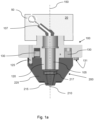
- Fig. 1a schematically shows a cut view of a dissection tool 200 attached to a tool interface 100 which form part of a dissection apparatus according to an embodiment of the invention.
- a first end of the dissection tool comprises a blade 210 for scraping off biological material from a tissue sample disposed on a slide.
- the apparatus further comprises an actuator 20 to which the tool interface 100 is fixed, which forms part of an assembly of actuators which are suitably controlled and moved in order to bring the scraping blade 210 into contact with a slide surface and detach biological material from an identified region of interest ROI of a tissue sample.
- the actuator 20 is movable in vertical direction and permits rotation about a vertical axis 150 and is used both during dissection and for automated attachment and detachment of the dissection tool, which will be explained in detail later.
- the depicted dissection tool is adapted to work in combination with suction.
- the tool thus comprises a nozzle 215 having an orifice where the blade 210 is arranged and an internal passageway that extends through the tool and connects with an internal passageway 105 through the tool interface 100.
- the internal passageways are connectable to a vacuum generator 50, via suitable tubing 107, so that during use of the tool, biological material dissected by the blade 210 is suctioned into the nozzle 215, where it is caught at the underside of an air-permeable filter element 217 arranged to span the tool internal passageway.
- the tool 200 is designed for single use.
- the tool 200 At the end of the dissection process, the tool 200 must be detached from the interface 100.
- the actuator 20 To enable high-resolution and high-precision dissection at relatively high speed, it is important that the actuator 20 is lightweight and compact.
- the tool 200 can be detached from the interface 100 and a new tool attached in an automated manner that does not add to the complexity and the weight of the assembly of actuators.
- the attachment interface 100 of the invention is thus designed to enable precise, stable and airtight attachment of the tool 200, followed by detachment, in a straightforward, automated manner that requires the actuator 20 to exert minimal force.
- Fig. 1b shows a perspective view of the underside of the inventive tool interface 100
- Fig. 1c shows a cross-sectional view of the dissection tool 200.
- the interface 100 comprises a housing 110 which has a generally planar underside 115 from which a central conical protrusion 120 extends.
- the protrusion 120 is hollow and forms part of the internal passageway 105 explained above.
- a body 225 of the tool comprises a corresponding conical recess 220.
- the conical protrusion 120 and the conical recess 220 have a common centre axis, which coincides with the vertical rotation axis 150 (refer Fig. 1a ). This provides a self-aligning, airtight connection between the tool and the interface.
- the interface may comprise an alignment pin 125 that fits into a corresponding hole that extends into the tool body 225. The geometry of the interface and the tool thus enables the tool to be attached with a precise location, which is necessary to enable the blade 210 to perform high-precision dissection.
- the locking force between the tool and the interface is realized via a press fit between the conical protrusion 120 and the conical recess 220.
- the locking force may be provided via a snap-fit connection.
- the conical protrusion 220 may comprise an annular ridge (not shown) which engages with snap-fit joints on the tool.
- the tool 200 comprises an upper collar 230 having an essentially flat upper surface 232, which surrounds an entrance to the conical recess 220.
- a number of snap-fit joints 235 - three in the depicted embodiment - are provided at the entrance to the conical recess, which engage with the annular ridge on the conical protrusion 120 when the interface protrusion is pushed into the tool recess.
- the snap-fit joints are cantilever arms that extend within a corresponding indentation 237 in the tool body 225 at the entrance to the conical recess 220.
- a gap between each arm 235 and a radially outer wall of the indentation 237 permits flexure of the arm needed for engagement and disengagement with the annular ridge on the interface conical protrusion 220.
- the snap fit joints 235 are arranged at even angular intervals around the entrance to the conical recess 220 and are adapted to provide a stable locking force that is sufficiently large to enable precise dissection using the tool, yet small enough to permit relatively low-force disengagement.
- the interface is provided with at least one lever arm that is pivotably connected to the interface 100 about a horizontal pivot axis and is moveable within the interface housing 110.
- the interface comprises three lever arms 130 which are arranged within the housing, at a radially outer location relative to the conical protrusion 120.
- a first end of each lever arm has a first engagement surface 131 that extends beyond the generally planar underside 115 of the housing 110.
- a second end of each lever arm has a second engagement surface (not visible in Fig. 1b ) which can extend beyond the housing underside 115 when the lever arm is pivoted.
- the housing underside may comprise slots 117 that permit protrusion of the first and second engagement surface of each lever arm beyond the housing underside.
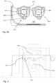
- Fig. 2 shows a side view of the tool 200 attached to the interface 100, whereby part of the housing 110 is cut away to show one of the three lever arms 130.
- the lever arm is pivotable about pivot axis 135, which axis is located closer to the second end of the lever arm than the first end.
- the first end of the lever arm has a vertical extension 133, which is generally located at a radial distance x, relative to the centre axis 150 of the interface conical protrusion, whereby x is larger than an outer radius of the tool upper collar 230.
- the vertical extension 133 thus lies radially outside of the tool upper collar 230 such the first engagement surface 131 makes no contact with the tool.
- the vertical extension 133 is sufficiently long to extend beyond an underside of the tool collar 230.
- the second end of the pivot arm is generally located at a shorter radial distance y relative to the centre axis 150 than the first end of the lever arm.
- the distance y is such that when the tool is in attached condition, the second engagement surface 132 of the lever arm 130 lies above the upper surface 232 of the upper collar 230.
- the second engagement surface may be in contact with the collar upper surface or there may be a small gap.
- Displacement of the first engagement surface 131 of the lever arm 130 in an upward direction brings the second engagement surface 132 into contact with the collar upper surface 232 and exerts a force on the tool.
- the lever force exerted by the three lever arms is sufficient to overcome the locking force between the tool and the interface. In the embodiment where the tool is secured to the interface via snap fit joints, the combined lever force pushes the tool out of the engaged locking position.
- the tool is deposited into a tool carrier tray 300, an example of which is shown in Fig. 3a .
- the tray comprises a number of tool carriers each of which comprises a recess 305 that is shaped to receive a tool body.
- a tool is picked up from a tool carrier and replaced in the same carrier after use.
- Fig. 3b shows a top view of two adjacent tool carriers 310, 320 in the carrier tray 300.
- Each tool carrier comprises an identically shaped main recess 305 for accommodating a tool.
- each carrier is shaped such that when a tool is held therein, the upper surface 232 of the tool upper collar does not protrude beyond an upper surface 315 of the tray.
- Each carrier further comprises three indentations 311, 312, 313 relative to the tray upper surface 315, which are located radially outwards of the main recess 305 and which are adapted to the receive the first engagement surface 131 of each lever arm 130 of the tool interface 100. Let us assume that the interface will pick up a tool arranged in the first carrier 310.
- the actuator lowers the conical protrusion of the interface into the first carrier 310, when the interface 100 is in a first angular position, being a pickup position in which the first engagement surface 131 of each lever arm is in alignment with the corresponding indentations 311, 312, 313 in the carrier.
- Fig. 4 shows the tool interface 100 after it has been lowered into the first carrier 310 for picking up a tool.
- the conical protrusion of the tool interface 100 can be lowered into the first carrier 310 without engagement of the lever arm 130 because the first engagement surface 131 is in alignment with the first indentation 311 of the first carrier 310.
- the first engagement surface of the second and third lever arms are in alignment with the second and third indentations 312, 313 respectively.
- the indentations have a sufficient depth to enable the conical protrusion 120 to be lowered until the annular ridge engages with the snap joints 235 at the entrance to the tool conical recess 220.
- the tray of carriers is able to flex somewhat, such that the tool can be displaced in the X-Y plane while being held in the recess 305, to enhance alignment.
- the actuator rotates the interface 100 about the vertical axis 150 to a second angular position, in which the first engagement surface of each lever arm is out of alignment with the indentations and will make contact with the upper surface 315 of the tray.
- the second angular position is a half turn from the first angular position, given that the tool body, and shaped recess 305, has two degrees of rotational symmetry.
- Other configurations are of course possible.
- the actuator raises the interface 100 until the conical protrusion 120 is above the tray and can be moved to pick up a new tool that is arranged in an adjacent tool carrier of the carrier tray.
- the only necessary actions of the actuator 20 to perform automated tool pickup and depositing are rotation about a vertical axis, free from load, and downward movement involving the application of low force. This can be achieved using a compact and lightweight actuator.
- any reference signs placed between parentheses shall not be construed as limiting the claim.
- Use of the verb "comprise” and its conjugations does not exclude the presence of elements or steps other than those stated in a claim.
- the article "a” or “an” preceding an element does not exclude the presence of a plurality of such elements.
- the invention may be implemented by means of hardware comprising several distinct elements, and by means of a suitably programmed computer. In the device claim enumerating several means, several of these means may be embodied by one and the same item of hardware. The mere fact that certain measures are recited in mutually different dependent claims does not indicate that a combination of these measures cannot be used to advantage.
Landscapes
- Physics & Mathematics (AREA)
- Health & Medical Sciences (AREA)
- Life Sciences & Earth Sciences (AREA)
- Chemical & Material Sciences (AREA)
- Analytical Chemistry (AREA)
- Biochemistry (AREA)
- General Health & Medical Sciences (AREA)
- General Physics & Mathematics (AREA)
- Immunology (AREA)
- Pathology (AREA)
- Surgical Instruments (AREA)
- Sampling And Sample Adjustment (AREA)
Claims (15)
- Die Einrichtung zum Sezieren von biologischem Material aus einer Probe, die auf einem ebenen Substrat angeordnet ist, das eine Werkzeugschnittstelle (100) zum freigebbaren Anbringen eines Sezierwerkzeugs (200), das über mindestens einen Schiebeanschluss (120, 220) mit der Schnittstelle verbindbar und um eine vertikale Drehachse (150) drehbar ist, umfasst, das weiter eine Betätigungsvorrichtung (20) in fester Verbindung mit der Schnittstelle (100) umfasst, wobei die Betätigungsvorrichtung (20) in vertikaler Richtung bewegbar und zwischen einer ersten Winkelposition und einer zweiten Winkelposition um die vertikale Drehachse (150) drehbar ist;dadurch gekennzeichnet, dass die Schnittstelle (100) weiter einen oder mehrere Hebelarme (130) umfasst, die jeweils über eine horizontale Schwenkachse (135) schwenkbar mit einem Gehäuse (110) der Schnittstelle verbunden sind, wodurch:- jeder Hebelarm (130) an einer radial äußeren Stelle relativ zu dem mindestens einen Schiebeanschluss eingerichtet ist und ein erstes und ein zweites Ende mit einer jeweiligen ersten und zweiten Eingriffsoberfläche (131, 132) aufweist, wobei die erste Eingriffsoberfläche (131) in einem größeren radialen Abstand von der vertikalen Achse (150) eingerichtet ist als die zweite Eingriffsoberfläche (132); und- das Werkzeug (200) einen oberen Bund (230) aufweist, der derart bemessen ist, dass, wenn das Werkzeug an der Schnittstelle (100) angebracht ist, die erste Eingriffsoberfläche (131) jedes Hebelarms (130) außerhalb einer Außenabmessung des oberen Bundes liegt und keinen Kontakt mit diesem hat, und weiter derart bemessen ist, dass die zweite Eingriffsoberfläche (132) jedes Hebelarms mit einer oberen Oberfläche (232) des Bundes in Kontakt kommt, wenn das erste Ende des Hebelarms nach oben verlagert wird,und dadurch, dass- die Einrichtung weiter einen Behälter (310) umfasst, der eine Öffnung (305) von ausreichender Tiefe aufweist, um einen Hauptkörper (225) des Werkzeugs aufzunehmen, und dazu konfiguriert ist, das Werkzeug durch Senken der Schnittstelle (100) in Richtung der Öffnung zu lösen, bis die erste Eingriffsoberfläche (131) jedes Hebelarms mit einer Oberfläche (315) in Kontakt kommt, die die Öffnung umgibt, und nach oben verlagert wird, wodurch die zweite Eingriffsoberfläche (132) eine Kraft auf den Bund (230), die den mindestens einen Schiebeanschluss ausrückt, ausübt.
- Die Einrichtung nach Anspruch 1, wobei der Behälter ein Werkzeugträger (310) ist, der eine Hauptvertiefung (305) aufweist, die dazu geformt ist, den Hauptkörper (225) des Sezierwerkzeugs (200) aufzunehmen, und eine obere Oberfläche (315), die die Hauptvertiefung umgibt, wodurch:- die obere Oberfläche des Trägers eine Anzahl relativ höherer Abschnitte und relativ niedrigerer Abschnitte (311, 312, 313) einschließt, die mindestens gleich der Anzahl der Hebelarme (130) der Werkzeugschnittstelle ist; und- die Position der relativ niedrigeren Abschnitte mit der Position der ersten Eingriffsoberfläche (131) jedes Hebelarms übereinstimmt, wenn sich die Schnittstelle in der ersten Winkelposition befindet.
- Die Einrichtung nach Anspruch 2, das eine Schale (300) umfasst, in der eine Vielzahl von Werkzeugträgern (310, 320) zum Halten einer Vielzahl von Sezierwerkzeugen eingebaut ist.
- Die Einrichtung nach Anspruch 2 oder 3, wobei die Einrichtung weiter dazu konfiguriert ist, ein in einem Werkzeugträger (310) eingerichtetes Sezierwerkzeug (200) anzubringen, wenn sich die Schnittstelle in der ersten Winkelposition befindet, indem die Schnittstelle relativ zu dem Werkzeugträger (310) nach unten bewegt wird, bis der mindestens eine Schiebeanschluss eingreift, wodurch eine Tiefe der relativ unteren Abschnitte (311, 312, 313) derart ist, dass dieser Eingriff auftritt, ohne durch den Kontakt zwischen der ersten Eingriffsoberfläche (131) jedes Hebelarms (130) und dem Werkzeugträger (310) beeinträchtigt zu werden.
- Die Einrichtung nach Anspruch 4, wobei die Einrichtung nach der Verwendung eines Werkzeugs weiter dazu konfiguriert ist, das Werkzeug zu dem Werkzeugträger (310) zurückzubringen und das Werkzeug von der Schnittstelle (100) zu lösen, durch:- Drehen der Schnittstelle in die zweite Winkelposition, die eine Position ist, in der die erste Eingriffsoberfläche (131) jedes Hebelarms mit den relativ höheren Abschnitten der oberen Trägeroberfläche (315) ausgerichtet ist; und- Senken des Werkzeugs in den Werkzeugträger (310) um eine Menge, die ausreicht, um die erste Eingriffsoberfläche (131) jedes Hebelarms mit den relativ höheren Abschnitten der oberen Oberfläche (315) des Trägers in Kontakt zu bringen und jeden Arm zum Schwenken zu veranlassen, so dass die Verlagerung der zweiten Eingriffsoberfläche (132) gegen die Werkzeugbundoberfläche (232) eine Kraft ausübt, die ausreicht, um den mindestens einen Schiebeanschluss auszurücken.
- Die Einrichtung nach einem vorstehenden Anspruch, wobei der mindestens eine Schiebeanschluss mindestens teilweise durch eine Schnappverbindung zwischen der Schnittstelle (100) und dem Werkzeug (200) gebildet ist.
- Die Einrichtung nach einem vorstehenden Anspruch, wobei:- die Schnittstelle (100) einen oder mehrere konische Vorsprünge (120), die sich von einer Unterseite (115) des Gehäuses (110) erstrecken, umfasst,- das Werkzeug (100) eine oder mehrere konische Vertiefungen (220) umfasst, die dazu geformt sind, den einen oder die mehreren konischen Vorsprünge aufzunehmen, und- der mindestens eine Schiebeanschluss mindestens teilweise durch das Eingreifen eines oder mehrerer konischer Vorsprünge (120) in die entsprechenden konischen Vertiefungen (220) gebildet ist.
- Die Einrichtung nach Anspruch 7, wobei der eine oder die mehreren konischen Vorsprünge (120) einen ringförmigen Grat umfassen und ein Eingang zu der einen oder den mehreren konischen Werkzeugvertiefungen (220) mit einer oder mehreren Schnappverbindungen (235) versehen ist, die in den ringförmigen Grat eingreifen, wenn ein Endteilabschnitt des konischen Vorsprungs in die entsprechende konische Vertiefung gedrückt wird.
- Die Einrichtung nach Anspruch 7 oder 8, wobei die Schnittstelle (100) einen zentralen konischen Vorsprung (120) umfasst, der zum Eingreifen in eine zentrale konische Vertiefung (220) des Werkzeugs (200) angepasst ist.
- Die Einrichtung nach einem vorstehenden Anspruch, wobei:- die Schnittstelle (100) einen inneren Durchgang (105) umfasst, der sich in vertikaler Richtung durch die Schnittstelle erstreckt und mit einem Anschlussstück versehen ist, um eine luftdichte Verbindung mit einem Vakuumgenerator (50) zu ermöglichen,- das Werkzeug (200) einen inneren Durchgang umfasst, der sich in vertikaler Richtung durch das Werkzeug erstreckt, und- wenn das Werkzeug in angebrachtem Zustand ist, die inneren Durchgänge des Werkzeugs und der Schnittstelle luftdicht verbunden sind.
- Die Einrichtung nach einem vorstehenden Anspruch, wobei:
die Schnittstelle zwei oder mehr Hebelarme umfasst, die in gleichmäßigem Winkelabstand um die vertikale Achse (150) eingerichtet sind. - Die Einrichtung nach einem er vorstehenden Anspruch, wobei in einer Ruheposition die erste Eingriffsoberfläche (131) jedes Hebelarms in einer ersten horizontalen Ebene liegt und die entsprechende zweite Eingriffsoberfläche (132) in einer zweiten horizontalen Ebene liegt, die höher ist als die erste horizontale Ebene.
- Das Verfahren zum Lösen eines Sezierwerkzeugs (200) von einer Werkzeugschnittstelle (100) einer Seziereinrichtung, wodurch das Sezierwerkzeug über mindestens einen Schiebeanschluss an der Werkzeugschnittstelle angebracht wird, und wobei:- die Einrichtung eine Betätigungsvorrichtung (20) in fester Verbindung mit der Werkzeugschnittstelle (100) umfasst, wobei die Betätigungsvorrichtung (20) in vertikaler Richtung bewegbar ist und zwischen einer ersten Winkelposition und einer zweiten Winkelposition um eine vertikale Drehachse (150) drehbar ist;- die Werkzeugschnittstelle (100) einen oder mehrere Hebelarme (130) umfasst, die jeweils über eine horizontale Schwenkachse (135) schwenkbar mit einem Gehäuse (110) der Schnittstelle verbunden sind,- jeder Hebelarm (130) an einer radial äußeren Stelle relativ zu dem mindestens einen Schiebeanschluss eingerichtet ist und ein erstes und ein zweites Ende mit einer jeweiligen ersten und zweiten Eingriffsoberfläche (131, 132) aufweist, wobei die erste Eingriffsoberfläche (131) in einem größeren radialen Abstand von der vertikalen Achse (150) eingerichtet ist als die zweite Eingriffsoberfläche (132);- das Werkzeug (200) einen oberen Bund aufweist, der derart bemessen ist, dass, wenn das Werkzeug an der Schnittstelle (100) angebracht ist, die erste Eingriffsoberfläche (131) jedes Hebelarms (130) außerhalb einer Außenabmessung des oberen Bundes (230) liegt und keinen Kontakt mit diesem hat, und weiter derart bemessen ist, dass die zweite Eingriffsoberfläche (132) jedes Hebelarms mit der oberen Oberfläche (232) des Bundes in Kontakt kommt, wenn das erste Ende des Hebelarms nach oben verlagert wird,wobei das Verfahren einen Schritt umfasst:- Senken der Schnittstelle (100) relativ zu einem Behälter, der eine Öffnung mit ausreichender Tiefe aufweist, um einen Hauptkörper (225) des Werkzeugs aufzunehmen, bis die erste Eingriffsoberfläche (131) jedes Hebelarms mit einer Oberfläche (315) in Kontakt kommt, die die Öffnung umgibt, und eine Verlagerung des ersten Endes nach oben verursacht, so dass die zweite Eingriffsoberfläche (132) eine Kraft auf den Bund (230) ausübt, die den mindestens einen Schiebeanschluss ausrückt.
- Das Verfahren nach Anspruch 13, wobei der Behälter ein Werkzeugträger (310) ist, der eine Hauptvertiefung (305) aufweist, die dazu geformt ist, den Körper (225) des Sezierwerkzeugs aufzunehmen, und eine obere Oberfläche (315), die die Hauptvertiefung umgibt, wodurch die obere Oberfläche des Trägers eine Anzahl relativ höherer Abschnitte und relativ niedrigerer Abschnitte (311, 312, 313) einschließt, die mindestens gleich der Anzahl der Hebelarme (130) der Werkzeugschnittstelle ist, wobei die Position der relativ niedrigeren Abschnitte mit der Position der ersten Eingriffsoberfläche (131) jedes Hebelarms übereinstimmt, wenn sich die Schnittstelle in der ersten Winkelposition befindet, und wobei das Verfahren vor dem Schritt des Senkens weiter umfasst:- Drehen der Werkzeugschnittstelle und des daran angebrachten Werkzeugs um die vertikale Achse (150), lastfrei, in die zweite Winkelposition, in der die erste Eingriffsoberfläche (131) jedes Hebelarms mit den relativ höheren Abschnitten der oberen Trägeroberfläche (315) ausgerichtet ist.
- Das Verfahren nach Anspruch 14, wobei das Sezierwerkzeug (200) vor der Befestigung in dem Werkzeugträger (310) eingerichtet und an der Schnittstelle (100) angebracht wird durch:- Drehen der Schnittstelle in die erste Winkelposition, in der die Position der relativ unteren Abschnitte (311, 312, 313) des Werkzeugträgers mit der Position der ersten Eingriffsoberfläche (131) jedes Hebelarms übereinstimmt, und- Senken der Schnittstelle relativ zu dem Werkzeugträger um eine Menge, die ausreicht, um den mindestens einen Schiebeanschluss einzurücken.
Applications Claiming Priority (2)
| Application Number | Priority Date | Filing Date | Title |
|---|---|---|---|
| EP21178992 | 2021-06-11 | ||
| PCT/EP2022/065711 WO2022258760A1 (en) | 2021-06-11 | 2022-06-09 | Apparatus comprising an interface for detachable coupling of a dissection tool |
Publications (3)
| Publication Number | Publication Date |
|---|---|
| EP4352483A1 EP4352483A1 (de) | 2024-04-17 |
| EP4352483B1 true EP4352483B1 (de) | 2025-01-29 |
| EP4352483C0 EP4352483C0 (de) | 2025-01-29 |
Family
ID=76623840
Family Applications (1)
| Application Number | Title | Priority Date | Filing Date |
|---|---|---|---|
| EP22732224.5A Active EP4352483B1 (de) | 2021-06-11 | 2022-06-09 | Vorrichtung mit einer schnittstelle zur lösbaren kopplung eines sezierwerkzeugs |
Country Status (5)
| Country | Link |
|---|---|
| US (1) | US20250137889A1 (de) |
| EP (1) | EP4352483B1 (de) |
| JP (1) | JP2024523840A (de) |
| CN (1) | CN117795310A (de) |
| WO (1) | WO2022258760A1 (de) |
Family Cites Families (6)
| Publication number | Priority date | Publication date | Assignee | Title |
|---|---|---|---|---|
| DE19917855A1 (de) | 1998-04-20 | 2000-01-13 | Biotul Bio Instr Gmbh | Abstreifeinrichtung für eine Pipettenspitze |
| KR101858780B1 (ko) | 2011-01-24 | 2018-05-16 | 닐스 비. 에이디 | 재료 샘플로부터 재료를 추출하기 위한 장치, 시스템, 및 방법 |
| EP2732877B1 (de) * | 2012-11-19 | 2019-04-03 | Brand Gmbh + Co Kg | Kolbenhubpipette mit welchselbarer Verdrängereinheit |
| DE102016111912A1 (de) | 2016-06-29 | 2018-01-04 | Eppendorf Ag | Dosierkopf, Dosiervorrichtung umfassend einen Dosierkopf und Verfahren zum Dosieren mittels eines Dosierkopfes |
| US10876933B2 (en) | 2016-11-09 | 2020-12-29 | Ventana Medical Systems, Inc. | Automated tissue dissection instrument and methods of using the same |
| JP7324785B2 (ja) * | 2018-06-21 | 2023-08-10 | ジェノミック ヘルス, インコーポレイテッド | 分析前基板処理のためのシステム及び方法 |
-
2022
- 2022-06-09 US US18/567,446 patent/US20250137889A1/en active Pending
- 2022-06-09 EP EP22732224.5A patent/EP4352483B1/de active Active
- 2022-06-09 CN CN202280054767.5A patent/CN117795310A/zh active Pending
- 2022-06-09 JP JP2023575834A patent/JP2024523840A/ja active Pending
- 2022-06-09 WO PCT/EP2022/065711 patent/WO2022258760A1/en not_active Ceased
Also Published As
| Publication number | Publication date |
|---|---|
| CN117795310A (zh) | 2024-03-29 |
| EP4352483A1 (de) | 2024-04-17 |
| US20250137889A1 (en) | 2025-05-01 |
| EP4352483C0 (de) | 2025-01-29 |
| WO2022258760A1 (en) | 2022-12-15 |
| JP2024523840A (ja) | 2024-07-02 |
Similar Documents
| Publication | Publication Date | Title |
|---|---|---|
| JP7295295B2 (ja) | 試料の診断検査のための自動試料調製システム | |
| US12228483B2 (en) | System and method for the automated preparation of biological samples | |
| US10900009B2 (en) | Method and device for automated removal of cells and/or cell colonies | |
| US7816128B2 (en) | Automatic cell cultivation apparatus having a multijoint robot | |
| TWI792862B (zh) | 自動化製備生物樣本之方法 | |
| CN109073664B (zh) | 自动诊断分析仪及其操作方法 | |
| CN106574935B (zh) | 试剂承载单元、用于操作试剂承载单元的适配器以及方法 | |
| JP2021536014A (ja) | 自動位置学習による診断テストのためのロボットサンプル作成システム | |
| US20240027305A1 (en) | Method, tool and apparatus for dissecting and transferring biological material | |
| US20240307883A1 (en) | Labware aligning systems and liquid handling systems and methods including same | |
| US20230393105A1 (en) | Support fixture for chromatography columns | |
| EP4179337A1 (de) | Robotisches probenhandhabungssystem | |
| EP4352483B1 (de) | Vorrichtung mit einer schnittstelle zur lösbaren kopplung eines sezierwerkzeugs | |
| JP2010504505A (ja) | 微細なサンプルを捕捉し、輸送し、沈着させる装置および方法 | |
| JP2024542991A (ja) | 自動診断分析装置の較正及び設計 | |
| US20250027961A1 (en) | System and method for the automated preparation of biological samples | |
| EP4202444B1 (de) | Mehrkanal-pipettierkopf | |
| JP2024533340A (ja) | 自動診断分析装置における在庫ハンドリングのための装置及び方法 |
Legal Events
| Date | Code | Title | Description |
|---|---|---|---|
| STAA | Information on the status of an ep patent application or granted ep patent |
Free format text: STATUS: UNKNOWN |
|
| STAA | Information on the status of an ep patent application or granted ep patent |
Free format text: STATUS: THE INTERNATIONAL PUBLICATION HAS BEEN MADE |
|
| PUAI | Public reference made under article 153(3) epc to a published international application that has entered the european phase |
Free format text: ORIGINAL CODE: 0009012 |
|
| STAA | Information on the status of an ep patent application or granted ep patent |
Free format text: STATUS: REQUEST FOR EXAMINATION WAS MADE |
|
| 17P | Request for examination filed |
Effective date: 20240111 |
|
| AK | Designated contracting states |
Kind code of ref document: A1 Designated state(s): AL AT BE BG CH CY CZ DE DK EE ES FI FR GB GR HR HU IE IS IT LI LT LU LV MC MK MT NL NO PL PT RO RS SE SI SK SM TR |
|
| DAV | Request for validation of the european patent (deleted) | ||
| DAX | Request for extension of the european patent (deleted) | ||
| GRAP | Despatch of communication of intention to grant a patent |
Free format text: ORIGINAL CODE: EPIDOSNIGR1 |
|
| STAA | Information on the status of an ep patent application or granted ep patent |
Free format text: STATUS: GRANT OF PATENT IS INTENDED |
|
| INTG | Intention to grant announced |
Effective date: 20241024 |
|
| GRAS | Grant fee paid |
Free format text: ORIGINAL CODE: EPIDOSNIGR3 |
|
| GRAA | (expected) grant |
Free format text: ORIGINAL CODE: 0009210 |
|
| STAA | Information on the status of an ep patent application or granted ep patent |
Free format text: STATUS: THE PATENT HAS BEEN GRANTED |
|
| AK | Designated contracting states |
Kind code of ref document: B1 Designated state(s): AL AT BE BG CH CY CZ DE DK EE ES FI FR GB GR HR HU IE IS IT LI LT LU LV MC MK MT NL NO PL PT RO RS SE SI SK SM TR |
|
| REG | Reference to a national code |
Ref country code: GB Ref legal event code: FG4D |
|
| REG | Reference to a national code |
Ref country code: CH Ref legal event code: EP |
|
| REG | Reference to a national code |
Ref country code: DE Ref legal event code: R096 Ref document number: 602022010235 Country of ref document: DE |
|
| REG | Reference to a national code |
Ref country code: IE Ref legal event code: FG4D |
|
| U01 | Request for unitary effect filed |
Effective date: 20250211 |
|
| U07 | Unitary effect registered |
Designated state(s): AT BE BG DE DK EE FI FR IT LT LU LV MT NL PT RO SE SI Effective date: 20250218 |
|
| PG25 | Lapsed in a contracting state [announced via postgrant information from national office to epo] |
Ref country code: RS Free format text: LAPSE BECAUSE OF FAILURE TO SUBMIT A TRANSLATION OF THE DESCRIPTION OR TO PAY THE FEE WITHIN THE PRESCRIBED TIME-LIMIT Effective date: 20250429 |
|
| PG25 | Lapsed in a contracting state [announced via postgrant information from national office to epo] |
Ref country code: PL Free format text: LAPSE BECAUSE OF FAILURE TO SUBMIT A TRANSLATION OF THE DESCRIPTION OR TO PAY THE FEE WITHIN THE PRESCRIBED TIME-LIMIT Effective date: 20250129 |
|
| PG25 | Lapsed in a contracting state [announced via postgrant information from national office to epo] |
Ref country code: ES Free format text: LAPSE BECAUSE OF FAILURE TO SUBMIT A TRANSLATION OF THE DESCRIPTION OR TO PAY THE FEE WITHIN THE PRESCRIBED TIME-LIMIT Effective date: 20250129 |
|
| PG25 | Lapsed in a contracting state [announced via postgrant information from national office to epo] |
Ref country code: NO Free format text: LAPSE BECAUSE OF FAILURE TO SUBMIT A TRANSLATION OF THE DESCRIPTION OR TO PAY THE FEE WITHIN THE PRESCRIBED TIME-LIMIT Effective date: 20250429 Ref country code: IS Free format text: LAPSE BECAUSE OF FAILURE TO SUBMIT A TRANSLATION OF THE DESCRIPTION OR TO PAY THE FEE WITHIN THE PRESCRIBED TIME-LIMIT Effective date: 20250529 |
|
| PG25 | Lapsed in a contracting state [announced via postgrant information from national office to epo] |
Ref country code: HR Free format text: LAPSE BECAUSE OF FAILURE TO SUBMIT A TRANSLATION OF THE DESCRIPTION OR TO PAY THE FEE WITHIN THE PRESCRIBED TIME-LIMIT Effective date: 20250129 |
|
| PG25 | Lapsed in a contracting state [announced via postgrant information from national office to epo] |
Ref country code: GR Free format text: LAPSE BECAUSE OF FAILURE TO SUBMIT A TRANSLATION OF THE DESCRIPTION OR TO PAY THE FEE WITHIN THE PRESCRIBED TIME-LIMIT Effective date: 20250430 |
|
| U20 | Renewal fee for the european patent with unitary effect paid |
Year of fee payment: 4 Effective date: 20250630 |
|
| PG25 | Lapsed in a contracting state [announced via postgrant information from national office to epo] |
Ref country code: SM Free format text: LAPSE BECAUSE OF FAILURE TO SUBMIT A TRANSLATION OF THE DESCRIPTION OR TO PAY THE FEE WITHIN THE PRESCRIBED TIME-LIMIT Effective date: 20250129 |
|
| PG25 | Lapsed in a contracting state [announced via postgrant information from national office to epo] |
Ref country code: CZ Free format text: LAPSE BECAUSE OF FAILURE TO SUBMIT A TRANSLATION OF THE DESCRIPTION OR TO PAY THE FEE WITHIN THE PRESCRIBED TIME-LIMIT Effective date: 20250129 |
|
| PG25 | Lapsed in a contracting state [announced via postgrant information from national office to epo] |
Ref country code: SK Free format text: LAPSE BECAUSE OF FAILURE TO SUBMIT A TRANSLATION OF THE DESCRIPTION OR TO PAY THE FEE WITHIN THE PRESCRIBED TIME-LIMIT Effective date: 20250129 |
|
| PLBE | No opposition filed within time limit |
Free format text: ORIGINAL CODE: 0009261 |
|
| STAA | Information on the status of an ep patent application or granted ep patent |
Free format text: STATUS: NO OPPOSITION FILED WITHIN TIME LIMIT |
|
| REG | Reference to a national code |
Ref country code: CH Ref legal event code: L10 Free format text: ST27 STATUS EVENT CODE: U-0-0-L10-L00 (AS PROVIDED BY THE NATIONAL OFFICE) Effective date: 20251210 |
|
| 26N | No opposition filed |
Effective date: 20251030 |
|
| REG | Reference to a national code |
Ref country code: CH Ref legal event code: H13 Free format text: ST27 STATUS EVENT CODE: U-0-0-H10-H13 (AS PROVIDED BY THE NATIONAL OFFICE) Effective date: 20260127 |
|
| PG25 | Lapsed in a contracting state [announced via postgrant information from national office to epo] |
Ref country code: MC Free format text: LAPSE BECAUSE OF FAILURE TO SUBMIT A TRANSLATION OF THE DESCRIPTION OR TO PAY THE FEE WITHIN THE PRESCRIBED TIME-LIMIT Effective date: 20250129 |