EP4352433B1 - Medical contact shock freezer - Google Patents
Medical contact shock freezer Download PDFInfo
- Publication number
- EP4352433B1 EP4352433B1 EP22741540.3A EP22741540A EP4352433B1 EP 4352433 B1 EP4352433 B1 EP 4352433B1 EP 22741540 A EP22741540 A EP 22741540A EP 4352433 B1 EP4352433 B1 EP 4352433B1
- Authority
- EP
- European Patent Office
- Prior art keywords
- stage
- freezing
- refrigerant
- pair
- plates
- Prior art date
- Legal status (The legal status is an assumption and is not a legal conclusion. Google has not performed a legal analysis and makes no representation as to the accuracy of the status listed.)
- Active
Links
Images


Classifications
-
- A—HUMAN NECESSITIES
- A01—AGRICULTURE; FORESTRY; ANIMAL HUSBANDRY; HUNTING; TRAPPING; FISHING
- A01N—PRESERVATION OF BODIES OF HUMANS OR ANIMALS OR PLANTS OR PARTS THEREOF; BIOCIDES, e.g. AS DISINFECTANTS, AS PESTICIDES OR AS HERBICIDES; PEST REPELLANTS OR ATTRACTANTS; PLANT GROWTH REGULATORS
- A01N1/00—Preservation of bodies of humans or animals, or parts thereof
- A01N1/10—Preservation of living parts
- A01N1/14—Mechanical aspects of preservation; Apparatus or containers therefor
- A01N1/142—Apparatus
- A01N1/144—Apparatus for temperature control, e.g. refrigerators or freeze-drying apparatus
-
- F—MECHANICAL ENGINEERING; LIGHTING; HEATING; WEAPONS; BLASTING
- F25—REFRIGERATION OR COOLING; COMBINED HEATING AND REFRIGERATION SYSTEMS; HEAT PUMP SYSTEMS; MANUFACTURE OR STORAGE OF ICE; LIQUEFACTION SOLIDIFICATION OF GASES
- F25B—REFRIGERATION MACHINES, PLANTS OR SYSTEMS; COMBINED HEATING AND REFRIGERATION SYSTEMS; HEAT PUMP SYSTEMS
- F25B13/00—Compression machines, plants or systems, with reversible cycle
-
- F—MECHANICAL ENGINEERING; LIGHTING; HEATING; WEAPONS; BLASTING
- F25—REFRIGERATION OR COOLING; COMBINED HEATING AND REFRIGERATION SYSTEMS; HEAT PUMP SYSTEMS; MANUFACTURE OR STORAGE OF ICE; LIQUEFACTION SOLIDIFICATION OF GASES
- F25B—REFRIGERATION MACHINES, PLANTS OR SYSTEMS; COMBINED HEATING AND REFRIGERATION SYSTEMS; HEAT PUMP SYSTEMS
- F25B40/00—Subcoolers, desuperheaters or superheaters
-
- F—MECHANICAL ENGINEERING; LIGHTING; HEATING; WEAPONS; BLASTING
- F25—REFRIGERATION OR COOLING; COMBINED HEATING AND REFRIGERATION SYSTEMS; HEAT PUMP SYSTEMS; MANUFACTURE OR STORAGE OF ICE; LIQUEFACTION SOLIDIFICATION OF GASES
- F25B—REFRIGERATION MACHINES, PLANTS OR SYSTEMS; COMBINED HEATING AND REFRIGERATION SYSTEMS; HEAT PUMP SYSTEMS
- F25B41/00—Fluid-circulation arrangements
- F25B41/30—Expansion means; Dispositions thereof
- F25B41/37—Capillary tubes
-
- F—MECHANICAL ENGINEERING; LIGHTING; HEATING; WEAPONS; BLASTING
- F25—REFRIGERATION OR COOLING; COMBINED HEATING AND REFRIGERATION SYSTEMS; HEAT PUMP SYSTEMS; MANUFACTURE OR STORAGE OF ICE; LIQUEFACTION SOLIDIFICATION OF GASES
- F25B—REFRIGERATION MACHINES, PLANTS OR SYSTEMS; COMBINED HEATING AND REFRIGERATION SYSTEMS; HEAT PUMP SYSTEMS
- F25B41/00—Fluid-circulation arrangements
- F25B41/40—Fluid line arrangements
- F25B41/42—Arrangements for diverging or converging flows, e.g. branch lines or junctions
-
- F—MECHANICAL ENGINEERING; LIGHTING; HEATING; WEAPONS; BLASTING
- F25—REFRIGERATION OR COOLING; COMBINED HEATING AND REFRIGERATION SYSTEMS; HEAT PUMP SYSTEMS; MANUFACTURE OR STORAGE OF ICE; LIQUEFACTION SOLIDIFICATION OF GASES
- F25B—REFRIGERATION MACHINES, PLANTS OR SYSTEMS; COMBINED HEATING AND REFRIGERATION SYSTEMS; HEAT PUMP SYSTEMS
- F25B43/00—Arrangements for separating or purifying gases or liquids; Arrangements for vaporising the residuum of liquid refrigerant, e.g. by heat
- F25B43/003—Filters
-
- F—MECHANICAL ENGINEERING; LIGHTING; HEATING; WEAPONS; BLASTING
- F25—REFRIGERATION OR COOLING; COMBINED HEATING AND REFRIGERATION SYSTEMS; HEAT PUMP SYSTEMS; MANUFACTURE OR STORAGE OF ICE; LIQUEFACTION SOLIDIFICATION OF GASES
- F25B—REFRIGERATION MACHINES, PLANTS OR SYSTEMS; COMBINED HEATING AND REFRIGERATION SYSTEMS; HEAT PUMP SYSTEMS
- F25B47/00—Arrangements for preventing or removing deposits or corrosion, not provided for in another subclass
- F25B47/02—Defrosting cycles
- F25B47/022—Defrosting cycles hot gas defrosting
- F25B47/025—Defrosting cycles hot gas defrosting by reversing the cycle
-
- F—MECHANICAL ENGINEERING; LIGHTING; HEATING; WEAPONS; BLASTING
- F25—REFRIGERATION OR COOLING; COMBINED HEATING AND REFRIGERATION SYSTEMS; HEAT PUMP SYSTEMS; MANUFACTURE OR STORAGE OF ICE; LIQUEFACTION SOLIDIFICATION OF GASES
- F25B—REFRIGERATION MACHINES, PLANTS OR SYSTEMS; COMBINED HEATING AND REFRIGERATION SYSTEMS; HEAT PUMP SYSTEMS
- F25B49/00—Arrangement or mounting of control or safety devices
- F25B49/02—Arrangement or mounting of control or safety devices for compression type machines, plants or systems
-
- F—MECHANICAL ENGINEERING; LIGHTING; HEATING; WEAPONS; BLASTING
- F25—REFRIGERATION OR COOLING; COMBINED HEATING AND REFRIGERATION SYSTEMS; HEAT PUMP SYSTEMS; MANUFACTURE OR STORAGE OF ICE; LIQUEFACTION SOLIDIFICATION OF GASES
- F25B—REFRIGERATION MACHINES, PLANTS OR SYSTEMS; COMBINED HEATING AND REFRIGERATION SYSTEMS; HEAT PUMP SYSTEMS
- F25B5/00—Compression machines, plants or systems, with several evaporator circuits, e.g. for varying refrigerating capacity
- F25B5/02—Compression machines, plants or systems, with several evaporator circuits, e.g. for varying refrigerating capacity arranged in parallel
-
- F—MECHANICAL ENGINEERING; LIGHTING; HEATING; WEAPONS; BLASTING
- F25—REFRIGERATION OR COOLING; COMBINED HEATING AND REFRIGERATION SYSTEMS; HEAT PUMP SYSTEMS; MANUFACTURE OR STORAGE OF ICE; LIQUEFACTION SOLIDIFICATION OF GASES
- F25B—REFRIGERATION MACHINES, PLANTS OR SYSTEMS; COMBINED HEATING AND REFRIGERATION SYSTEMS; HEAT PUMP SYSTEMS
- F25B7/00—Compression machines, plants or systems, with cascade operation, i.e. with two or more circuits, the heat from the condenser of one circuit being absorbed by the evaporator of the next circuit
-
- F—MECHANICAL ENGINEERING; LIGHTING; HEATING; WEAPONS; BLASTING
- F25—REFRIGERATION OR COOLING; COMBINED HEATING AND REFRIGERATION SYSTEMS; HEAT PUMP SYSTEMS; MANUFACTURE OR STORAGE OF ICE; LIQUEFACTION SOLIDIFICATION OF GASES
- F25D—REFRIGERATORS; COLD ROOMS; ICE-BOXES; COOLING OR FREEZING APPARATUS NOT OTHERWISE PROVIDED FOR
- F25D31/00—Other cooling or freezing apparatus
- F25D31/001—Plate freezers
-
- F—MECHANICAL ENGINEERING; LIGHTING; HEATING; WEAPONS; BLASTING
- F25—REFRIGERATION OR COOLING; COMBINED HEATING AND REFRIGERATION SYSTEMS; HEAT PUMP SYSTEMS; MANUFACTURE OR STORAGE OF ICE; LIQUEFACTION SOLIDIFICATION OF GASES
- F25B—REFRIGERATION MACHINES, PLANTS OR SYSTEMS; COMBINED HEATING AND REFRIGERATION SYSTEMS; HEAT PUMP SYSTEMS
- F25B2313/00—Compression machines, plants or systems with reversible cycle not otherwise provided for
- F25B2313/027—Compression machines, plants or systems with reversible cycle not otherwise provided for characterised by the reversing means
- F25B2313/02742—Compression machines, plants or systems with reversible cycle not otherwise provided for characterised by the reversing means using two four-way valves
-
- F—MECHANICAL ENGINEERING; LIGHTING; HEATING; WEAPONS; BLASTING
- F25—REFRIGERATION OR COOLING; COMBINED HEATING AND REFRIGERATION SYSTEMS; HEAT PUMP SYSTEMS; MANUFACTURE OR STORAGE OF ICE; LIQUEFACTION SOLIDIFICATION OF GASES
- F25B—REFRIGERATION MACHINES, PLANTS OR SYSTEMS; COMBINED HEATING AND REFRIGERATION SYSTEMS; HEAT PUMP SYSTEMS
- F25B2400/00—General features or devices for refrigeration machines, plants or systems, combined heating and refrigeration systems or heat-pump systems, i.e. not limited to a particular subgroup of F25B
- F25B2400/05—Compression system with heat exchange between particular parts of the system
- F25B2400/054—Compression system with heat exchange between particular parts of the system between the suction tube of the compressor and another part of the cycle
-
- F—MECHANICAL ENGINEERING; LIGHTING; HEATING; WEAPONS; BLASTING
- F25—REFRIGERATION OR COOLING; COMBINED HEATING AND REFRIGERATION SYSTEMS; HEAT PUMP SYSTEMS; MANUFACTURE OR STORAGE OF ICE; LIQUEFACTION SOLIDIFICATION OF GASES
- F25B—REFRIGERATION MACHINES, PLANTS OR SYSTEMS; COMBINED HEATING AND REFRIGERATION SYSTEMS; HEAT PUMP SYSTEMS
- F25B2400/00—General features or devices for refrigeration machines, plants or systems, combined heating and refrigeration systems or heat-pump systems, i.e. not limited to a particular subgroup of F25B
- F25B2400/07—Details of compressors or related parts
-
- F—MECHANICAL ENGINEERING; LIGHTING; HEATING; WEAPONS; BLASTING
- F25—REFRIGERATION OR COOLING; COMBINED HEATING AND REFRIGERATION SYSTEMS; HEAT PUMP SYSTEMS; MANUFACTURE OR STORAGE OF ICE; LIQUEFACTION SOLIDIFICATION OF GASES
- F25B—REFRIGERATION MACHINES, PLANTS OR SYSTEMS; COMBINED HEATING AND REFRIGERATION SYSTEMS; HEAT PUMP SYSTEMS
- F25B2400/00—General features or devices for refrigeration machines, plants or systems, combined heating and refrigeration systems or heat-pump systems, i.e. not limited to a particular subgroup of F25B
- F25B2400/12—Inflammable refrigerants
-
- F—MECHANICAL ENGINEERING; LIGHTING; HEATING; WEAPONS; BLASTING
- F25—REFRIGERATION OR COOLING; COMBINED HEATING AND REFRIGERATION SYSTEMS; HEAT PUMP SYSTEMS; MANUFACTURE OR STORAGE OF ICE; LIQUEFACTION SOLIDIFICATION OF GASES
- F25B—REFRIGERATION MACHINES, PLANTS OR SYSTEMS; COMBINED HEATING AND REFRIGERATION SYSTEMS; HEAT PUMP SYSTEMS
- F25B2500/00—Problems to be solved
- F25B2500/09—Improving heat transfers
-
- F—MECHANICAL ENGINEERING; LIGHTING; HEATING; WEAPONS; BLASTING
- F25—REFRIGERATION OR COOLING; COMBINED HEATING AND REFRIGERATION SYSTEMS; HEAT PUMP SYSTEMS; MANUFACTURE OR STORAGE OF ICE; LIQUEFACTION SOLIDIFICATION OF GASES
- F25B—REFRIGERATION MACHINES, PLANTS OR SYSTEMS; COMBINED HEATING AND REFRIGERATION SYSTEMS; HEAT PUMP SYSTEMS
- F25B2600/00—Control issues
- F25B2600/02—Compressor control
- F25B2600/027—Compressor control by controlling pressure
- F25B2600/0271—Compressor control by controlling pressure the discharge pressure
-
- F—MECHANICAL ENGINEERING; LIGHTING; HEATING; WEAPONS; BLASTING
- F25—REFRIGERATION OR COOLING; COMBINED HEATING AND REFRIGERATION SYSTEMS; HEAT PUMP SYSTEMS; MANUFACTURE OR STORAGE OF ICE; LIQUEFACTION SOLIDIFICATION OF GASES
- F25B—REFRIGERATION MACHINES, PLANTS OR SYSTEMS; COMBINED HEATING AND REFRIGERATION SYSTEMS; HEAT PUMP SYSTEMS
- F25B2600/00—Control issues
- F25B2600/11—Fan speed control
- F25B2600/111—Fan speed control of condenser fans
-
- F—MECHANICAL ENGINEERING; LIGHTING; HEATING; WEAPONS; BLASTING
- F25—REFRIGERATION OR COOLING; COMBINED HEATING AND REFRIGERATION SYSTEMS; HEAT PUMP SYSTEMS; MANUFACTURE OR STORAGE OF ICE; LIQUEFACTION SOLIDIFICATION OF GASES
- F25B—REFRIGERATION MACHINES, PLANTS OR SYSTEMS; COMBINED HEATING AND REFRIGERATION SYSTEMS; HEAT PUMP SYSTEMS
- F25B40/00—Subcoolers, desuperheaters or superheaters
- F25B40/04—Desuperheaters
-
- F—MECHANICAL ENGINEERING; LIGHTING; HEATING; WEAPONS; BLASTING
- F25—REFRIGERATION OR COOLING; COMBINED HEATING AND REFRIGERATION SYSTEMS; HEAT PUMP SYSTEMS; MANUFACTURE OR STORAGE OF ICE; LIQUEFACTION SOLIDIFICATION OF GASES
- F25D—REFRIGERATORS; COLD ROOMS; ICE-BOXES; COOLING OR FREEZING APPARATUS NOT OTHERWISE PROVIDED FOR
- F25D21/00—Defrosting; Preventing frosting; Removing condensed or defrost water
- F25D21/04—Preventing the formation of frost or condensate
Definitions
- This invention relates to a medical contact shock freezer adapted for fast freezing a plurality of individual bags containing blood plasma and to a method of freezing medical liquids.
- Blood plasma bags are commonly used to store, transport and dispense blood plasma and comprise flexible plastics walls which may be made of polyethylene, polypropylene or plasticized PVC.
- the plasma contained within a filled, sealed plasma bag to be completely frozen to a temperature of -30°C or less within a short time period.
- the step of rapidly freezing the plasma is facilitated by use of a contact shock freezer in which a plurality of plasma bags are pressed between cooling plates which are chilled by a circulating coolant. Once frozen, the plasma bags are transferred to a medical storage freezer which may be maintained at a temperature of -30°C, -50 °C or below.
- Contact shock freezers require a high refrigeration power in order to rapidly remove a significant quantity of heat from the sealed plasma bags. For example, a cooling power of over 1.5 kW is required to reduce the temperature of forty-eight 0.25l bags of plasma from 32°C to -30°C in less than 60 minutes. Consequently, contact shock freezers have typically been based on refrigeration circuits which use large, high power semi-hermetic compressors and large quantities of refrigerant. The power requirements for the medical storage freezers to which the shock frozen plasma bags are transferred is significantly lower and the cooling circuits for such medical storage freezers are thus designed accordingly.
- FR2632391 A1 relates to a rapid freezing device for bags of plasma or similar blood derivatives.
- WO 2008/112566 A2 provides a multistage refrigeration system.
- CN112195015 A provides a mixed refrigerant and a refrigerating system.
- WO 2015/045354 A1 provides a refrigerating device capable of effectively eliminating problems due to the formation of dry ice from carbon dioxide (R744).
- JP 2014 070832 A provides an ultra-low temperature refrigerator for storing cells and microbes.
- US 2018/146799 A1 and US 2018/146800 A1 disclose refrigerated display cases.
- the present invention provides a medical contact shock freezer in accordance with claim 1.
- the dependent claims define preferred or alternative features.
- the present invention is based upon the realisation that the combination of a cascade refrigeration system, particularly using fully hermetic compressors, can be adapted to provide a suitable cooling system for such a contact shock freezer; in the medical contact freezer of claim 1 each of the first stage compressor and the second stage compressor is a fully hermetic compressor. It is particularly surprising that such a contact shock freezer system can also use environmentally friendly green refrigerant gasses which are generally less efficient that the refrigerants traditionally used in high power contact shock freezer refrigeration circuits.
- the present invention provides, in one of its aspects, a surprising way of providing a contact shock freezer which uses environmentally friendly green refrigerant gasses, specifically hydrocarbon refrigerants gasses (and thus avoids the need to use refrigerant gasses in a contact shock freezer whose use is less desirable or outlawed, for example CFCs (ChloroFluoroCarbons), HCFCs (HydroChloroFluoroCarbons) and HFCs) by the use of a cascade refrigeration system for its contact shock freezer; in the medical contact freezer of claim 1 the first stage refrigerant is refrigerant grade propane and the second state refrigerant is refrigerant grade ethane.
- CFCs ChloroFluoroCarbons
- HCFCs HydroChloroFluoroCarbons
- HFCs a cascade refrigeration system for its contact shock freezer
- contact shock freezer means a freezer which is configured to clamp the individual bags containing a medical liquid between the freezing plates during the freezing process such that the surfaces of the bags in contact with the freezing plates are flattened; this increases the contact area and improves heat transfer. Sufficient force may be applied to clamp the bags between the freezing plates such that a pressure which is ⁇ 0.1 bar or ⁇ 0.2 bar and/or ⁇ 0.5 bar is generated in the medical liquid within the bags.
- Each bag to be frozen may have a nominal volume of 500 ml; in this case, each bag may contain about 250 ml of plasma, for example from a whole blood donation of 500 ml.
- Each pair of freezing plates is preferably substantially horizontal; this facilitates loading and unloading of the individual bags, for example by arranging the individual bags of medical liquid to be frozen on a heat conductive tray and loading the tray carrying the individual bags between the freezing plates when in their loading position.
- the freezing plates are preferably arranged at an angle of less to 30° to the horizontal.
- An improvement in the freezing cycle can be obtained by arranging the freezing plates at a small angle to the horizontal, for example at an angle of at least 2° or at least 3° with respect to the horizontal; this helps to mitigate against unintentional inclusion of air in the bags.
- An angle of between 3° and 10°, notably 5°, to the horizontal provides an advantageous effect combined with a configuration which facilitates loading and unloading of the bags.
- the or each pair of freezing plates may define an operating surface, that is to say a surface at which individual bags can be arranged for freezing, which has an area ⁇ 0.25 m 2 , ⁇ 0.3 m 2 , ⁇ 0.4 m 2 , ⁇ 0.5 m 2 , ⁇ 0.55 m 2 , ⁇ 0.7 m 2 or ⁇ 0.8 m 2 and/or ⁇ 1.4 m 2 , ⁇ 1.3 m 2 ⁇ 1.2 m 2 or ⁇ 1 m 2 .
- the or each pair of freezing plates may define an operating surface which has:
- Each of the first and second stage refrigerants is a non-CFC, non-HCFC, refrigerant.
- CFCs chlorofluorocarbons
- HCFCs hydrochlorofluorocarbons
- Refrigerants having even less environmental impact than HFCs are preferred so that each of the first and second stage refrigerants is a non-CFC, non-HCFC, non-HFC refrigerant, specifically a hydrocarbon refrigerant.
- the first stage refrigerant is R290 (propane).
- R290 propane
- the use of R290 (propane) as the first stage refrigerant is selected notably for its refrigerant properties combined with its availability which particularly facilitates replacement of the first stage refrigerant if this becomes necessary.
- the second stage refrigerant is R170 (ethane).
- the second stage refrigerant may include a small quantity, notably between 1 wt% and 5 wt%, of R601 (pentane); this facilitates the second stage oil return.
- R170 (ethane) as the second stage refrigerant is selected notably for its refrigerant properties combined with its availability which particularly facilitates replacement of the first stage refrigerant if this becomes necessary.
- R290 propane
- R170 ethane
- refrigerant grades of the materials i.e., grades (which are generally less than 100% pure) which are intended for and used for refrigeration applications.
- each of R290 (propane) and R170 (ethane) preferably and generally has a purity of at least 97.5 %.
- the present invention allows the contact shock freezer to be configured using quantities of these refrigerants that are sufficiently small to mitigate any associated risk.
- the first stage refrigeration circuit comprises less than 400, more preferably less than 300g and even more preferably less than 200g of the first stage refrigerant; and the second stage refrigeration circuit comprises less than 400g, more preferably less than 300g and even more preferably less than 200g of the second refrigerant.
- a contact shock freezer in which the first stage refrigerant is about 150g of R290 (propane) and the second stage refrigerant is about 150g of R170 (ethane) has been shown to be effective in allowing the freezing of 30 individual bags of 250 ml of blood plasma from 32 °C to -30 °C in under 40 minutes.
- part of the present invention is based upon the realisation that an effective contact shock freezer can be configured using such refrigerants in advantageously small quantities.
- the freezing plates may be configured to operate at a temperature which is ⁇ -40°C, ⁇ -45°C, ⁇ -50°C or ⁇ -55°C. This provides rapid shock freezing. This operating temperature is preferably reached with 30 minutes, within 25 minutes or within 20 minutes of initial operation of the shock freezer.
- the freeze time required to attain a core temperature of the medical liquid in the bags of -30 °C is preferably ⁇ 60 minutes, ⁇ 50 minutes or more preferably ⁇ 45 minutes, notably when the freezing plates are fully loaded with bags to be frozen at an initial temperature of 20 °C, notably bags each containing ⁇ 200 ml or ⁇ 250 ml and/or ⁇ 1000 ml or ⁇ 850 ml of blood plasma.
- each freezing plate is configured to operate at a temperature of about -60°C, notably within the range -55°C to -65°C, preferably within the range -58°C to -62°C; this provides good efficiency and heat transfer.
- the movement of the freezing plate(s) from the loading position to the freezing position is preferably a linear movement, notably a vertical linear movement, without rotation of either freezing plate.
- This facilitates accurate clamping of the plurality of bags between the plates.
- the freezing plates are parallel in their freezing position and remain parallel during movement between the loading and the freezing position. This further facilitates accurate clamping of the plurality of bags.
- the use of parallel and preferably planer freezing plates is also advantageous when it is desired for the shock freezer to be useable in a configuration having two layers of bags arranged between a pair of freezing plates.
- the angle of each freezing plate to the horizontal is fixed, that is to say this angle does not change; each freezing plate may be fixed in rotation so that it cannot rotate.
- At least one of the upper and lower freezing plates of a pair of freezing plates may be associated with a linear drive to affect its movement from the loading to the freezing position, for example one or more pneumatic or hydraulic cylinders, notably a pair of spaced cylinders, for example arranged at opposite sides of the freezing plate.
- the movement may be guided by a linear guide arrangement, for example comprising a linear guide arranged at each of the left and right sides of the freezing plate.
- Each linear guide may comprise a pair of, preferably vertical, tubular guide elements which together guide the movement.
- the first pair of freezing plates may comprise an upper freezing plate and a lower freezing plate, with the upper freezing plate being arranged above the lower freezing plate. This provides a convenient arrangement, notably where each of the upper and lower freezing plates is horizontal or substantially horizontal, for example arranged at an angle of less than 30 ° to the horizontal.
- the contact shock freezer may comprise a single pair of freezing plates. Alternately, the contact shock freezer may comprise two (and only two) pairs of freezing plates.
- one of the freezing plates of a pair of freezing plates is immobile and does not move during normal operation of the contact shock freezer with the other freezing plate of the pair being a moveable freezing plate; this provides a mechanically advantageous arrangement.
- An arrangement in which the shock freezer comprises:
- the contact shock freezer comprises two (and only two) pairs of freezing plates, comprising the first pair of freezing plates which comprises an upper freezing plate and a lower freezing plate, and
- the first and second pair of freezing plates are preferably arranged with one pair above the other.
- the lower freezing plate of the first pair of freezing plates and the upper freezing plate of the second pair of freezing plates are provided by a single, integrated and preferably immobile freezing plate.
- the first refrigeration circuit and the second refrigeration circuit are independently operable, that is to say, for example that one can be operated without the other.
- each pair of the two pairs of freezing plates to be operated independently, for example in the event of the capacity of one pair of freezing plates being sufficient for the number of bags it is desired to freeze simultaneously.
- each refrigeration circuit is preferably identical or substantially identical; this facilitates assembly and maintenance.
- the disclosure herein in relation to the components, configuration and arrangement of one of the refrigeration circuits applies equally to the equivalent components, configuration and arrangement of the other refrigeration circuit.
- the first stage compressor and the second stage compressor are fully hermetic compressors having a power of less than 3 hp, preferably less than 2.5 hp, more preferably less than 2 hp.
- the use of fully hermetic compressors allows the selection of appropriate compressors which are smaller, simpler, more efficient and/or easier to replace than other types of compressors. This may be used, in addition, to reduce the operating noise of the medical contact shock freezer.
- the inter-stage heat exchanger is preferably thermally insulated to reduce heat influx from the surrounding environment.
- the inter-stage heat exchanger may be enclosed within an insulated enclosure.
- Use of a multiple plate heat exchanger provides a robust arrangement which is suitable for the desired working temperatures.
- a multiple plate heat exchanger comprises a series of adjacently arranged, spaced parallel plates with the space between adjacent plates forming channels; the first stage and second stage refrigerants of the cascade refrigeration circuit flow through adjacent channels between the plates such that heat exchange occurs between the first stage and second stage refrigerants through the plates.
- An arrangement in which the first stage and second stage refrigerants cross the channels in series may be appropriate for the associated flow rate and heat exchange.
- the present invention provides a method of fast freezing a plurality of individual bags containing a medical liquid as defined in claim 14.
- the present invention provides for use of a first refrigeration circuit comprising a cascade refrigeration circuit comprising a first stage refrigeration circuit, a second stage refrigeration circuit and an inter-stage heat exchanger for fast freezing a plurality of individual bags containing a medical liquid, particularly blood plasma, clamped between a pair of freezing plates.
- the first stage refrigerant used in the first refrigeration circuit is a hydrocarbon refrigerant, specifically R290 (propane)
- the second stage refrigerant used in the second stage refrigeration circuit is also a hydrocarbon refrigerant, specifically R170 (ethane).
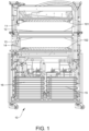
- the medical contract shock freezer 10 shown in Figs 1 and 2 comprises upper 11 and lower 12 freezing plates of a first pair of freezing plates 101 and upper 13 and lower 14 freezing plates of a second pair of freezing plates 102 , each pair of freezing plates having the same footprint (for example about 1 m wide by about 0.8 m deep) with the first pair of freezing plates 101 being arranged above the second pair of freezing plate 102 within the same footprint.
- the lower freezing plate 12 of the first pair of freezing plates and the upper freezing plate 13 of the second pair of freezing plates are provided by a single, immobile, integrated freezing plate.
- Each of the freezing plates 11, 12, 13, 14 is arranged at an angle of 5° to the horizontal sloping downwards from the rear of the contact shoch freezer to the front.
- Fig 1 shows the freezing plates 11, 12, 13,14 in their loading position in which sufficient separation is provided between the freezing plates of each pair to allow a heat conductive tray carrying individual bags of blood plasma (for example a heat conductive tray carrying fifteen individual bags, each containing 250 ml of blood plasma arranged in five rows in the width direction and three rows in the depth direction of the contact shock freezer) to be loaded between each pair of freezing plates prior to freezing.
- the loading position is also used during removal of the frozen plasma bags from between each pair of freezing plates subsequent to the freezing operation.
- the moveable freezing plate 11 of the first pair of freezing plates In order to clamp the plasma bags between their respective freezing plates for the freezing operation, the moveable freezing plate 11 of the first pair of freezing plates it moved vertically, linearly downwardly by vertically arranged hydraulic cylinders to clamp plasma bags between the first pair of freezing plates and the moveable freezing plate 14 of the first pair of freezing plates is moved vertically, linearly upwards by vertically arranged hydraulic cylinders to clamp plasma bags between the second pair of freezing plate. These movements are reversed to move from the freezing position to the loading position.
- the first 15 and second 16 cascade refrigeration circuits are independently operable so that each of the pairs of freezing plates can be operated independently of the other.
- Each of the refrigeration circuits is connected to its respective moveable freezing plates by flexible stainless-steel hoses of appropriate length.
- the components, and configuration of each of the individual refrigeration circuits 15,16 are preferably identical; consequently, only one of the refrigeration circuits 15 is described below.
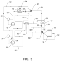
- Fig 3 illustrates the first refrigeration circuit 15 which comprises a cascade refrigeration circuit comprising a first stage refrigeration circuit S1, a second stage refrigeration circuit S2 and an inter-stage heat exchanger 17.
- first stage refrigerant is 150g of R290 (propane)
- second refrigerant is 150g of R170 (ethane). Operation during the refrigeration mode is described in the following paragraphs, the temperatures and pressures indicated being typical, order of magnitude values (given only by way of example) during stable operation during the refrigeration mode.
- the R290 (propane) first stage refrigerant is sequentially:
- the first stage refrigerant preferably enters the inter-stage heat exchanger in a mixed liquid and gas phase and exits the inter-stage heat exchanger in a gas phase.
- the R170 (ethane) second stage refrigerant is sequentially:
- Fig 4 is a schematic cross-section through a freezing plate 40 having a front edge 41, rear edge 42, left-hand edge 43 and right-hand edge 44 and which may be used as the upper freezing plate 11 of the first pair of freezing plates described above.
- a series of refrigerant baffles 45 arranged within the freezing plate 40 define a flow path for the second stage refrigerant (which in the illustrated example is a serpentine flow path) as it passes through the freezing plate between i) a first connecting orifice 46 for the second stage refrigerant which is situated at the front, left-hand corner of the freeing plate 40 and ii) a second connecting orifice 47 for the second stage refrigerant which is situated at the rear, left-hand corner of the freeing plate 40.
- Each of the freezing plates may be provided with one or more electrical defrost heaters.
- the freezing plate 40 of Fig 4 is provided with three electrical resistance defrost heaters 48a, 48b, 48c.
- electrical defrost heaters are provided for the freezing plates it is advantageous for the number of electrical defrost heaters to be a multiple of 3; this facilitates equilibrating the electrical load between each phase of a three-phase supply.
- one convenient configuration is to arrange three defrost heaters at each freezing plate, each of which is powered by a separate phase of a three-phase supply; this helps to equilibrate the load on the three-phase electrical supply by allowing the electrical resistance of the circuit of each of the three electrical phases to be similar or, preferably, the same.
- the inter-stage heat exchanger may be multiplate heat exchanger, preferably a brazed plate multiplate heat exchanger, a preferred arrangement of which is illustrated in Fig 5 .
- the multiplate heat exchanger 51 is preferably arranged within a heat insulated enclosure 52 containing the first stage capillary tube 21, the second stage filter/dryer 26 and the second stage capillary tube 27; any free space may be filled with insulating foam, for example PUR foam.
- the outlet of the first stage capillary tube 21 is connected to a first stage inlet 53 of the multiplate heat exchanger 51 with a first stage outlet 54 of the multiplate heat exchanger 51 being connected to return the first stage refrigerant to the first stage compressor 18.
- a second stage inlet 55 of the inter-stage heat exchanger 17 is fed with second stage refrigerant from an outlet of the second stage compressor 23 (via the second stage desuperheater 24 and anti-frost heat exchanger 25).
- a second stage outlet 26 of the inter-stage heat exchanger 17 feeds the second stage refrigerant to the second stage capillary tube 27 via the filter/dryer 26.
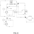
- Fig 6 illustrates an alternative arrangement in which defrosting of the freezing plates is provided by a first stage circuit reverser 61 and a second stage circuit reverser 62. In this case, electrical defrosting heaters are no longer required.
- the following considerations apply in relation to the specific refrigeration circuits described above, and also more broadly in relation to other refrigeration circuits which are disclosed herein and/or are used in relation to the inventions disclosed herein:
Landscapes
- Engineering & Computer Science (AREA)
- Physics & Mathematics (AREA)
- Thermal Sciences (AREA)
- General Engineering & Computer Science (AREA)
- Mechanical Engineering (AREA)
- Chemical & Material Sciences (AREA)
- Life Sciences & Earth Sciences (AREA)
- Combustion & Propulsion (AREA)
- Health & Medical Sciences (AREA)
- Dentistry (AREA)
- General Health & Medical Sciences (AREA)
- Wood Science & Technology (AREA)
- Zoology (AREA)
- Environmental Sciences (AREA)
- Analytical Chemistry (AREA)
- Power Engineering (AREA)
- Devices That Are Associated With Refrigeration Equipment (AREA)
Applications Claiming Priority (2)
| Application Number | Priority Date | Filing Date | Title |
|---|---|---|---|
| GBGB2110256.1A GB202110256D0 (en) | 2021-07-16 | 2021-07-16 | Medical contact shock freezer |
| PCT/EP2022/069852 WO2023285652A1 (en) | 2021-07-16 | 2022-07-15 | Medical contact shock freezer |
Publications (2)
| Publication Number | Publication Date |
|---|---|
| EP4352433A1 EP4352433A1 (en) | 2024-04-17 |
| EP4352433B1 true EP4352433B1 (en) | 2025-01-29 |
Family
ID=77443310
Family Applications (1)
| Application Number | Title | Priority Date | Filing Date |
|---|---|---|---|
| EP22741540.3A Active EP4352433B1 (en) | 2021-07-16 | 2022-07-15 | Medical contact shock freezer |
Country Status (6)
| Country | Link |
|---|---|
| US (1) | US20240328680A1 (da) |
| EP (1) | EP4352433B1 (da) |
| CN (1) | CN117677813A (da) |
| DK (1) | DK4352433T3 (da) |
| GB (1) | GB202110256D0 (da) |
| WO (1) | WO2023285652A1 (da) |
Families Citing this family (1)
| Publication number | Priority date | Publication date | Assignee | Title |
|---|---|---|---|---|
| GB202410275D0 (en) | 2024-07-15 | 2024-08-28 | B Medical Systems Sarl | Medical contact shock freezer |
Citations (2)
| Publication number | Priority date | Publication date | Assignee | Title |
|---|---|---|---|---|
| US20180146800A1 (en) * | 2015-04-29 | 2018-05-31 | Aht Cooling Systems Gmbh | Refrigerated display case |
| US20180146799A1 (en) * | 2015-06-16 | 2018-05-31 | Aht Cooling Systems Gmbh | Refrigerated display case |
Family Cites Families (15)
| Publication number | Priority date | Publication date | Assignee | Title |
|---|---|---|---|---|
| US1905131A (en) * | 1931-02-25 | 1933-04-25 | Frosted Foods Co Inc | Refrigerating apparatus |
| US3392541A (en) * | 1967-02-06 | 1968-07-16 | Larkin Coils Inc | Plural compressor reverse cycle refrigeration or heat pump system |
| IT1226765B (it) * | 1987-07-31 | 1991-02-06 | Samifi Stal Spa | Congelatore automatico a piastre refrigeranti orizzontali avente la capacita' di comprimere il prodotto durante la congelazione. |
| FR2632391A1 (fr) * | 1988-06-07 | 1989-12-08 | Trapani Sauveur | Dispositif de congelation rapide de poches de plasma et produits sanguins analogues |
| DE19736372A1 (de) * | 1997-08-21 | 1999-02-25 | Ingo Dipl Ing Heschel | Verfahren und Vorrichtung zum Kühlen, insbesondere Gefrieren eines Kühlgutes |
| US6393853B1 (en) * | 2000-12-19 | 2002-05-28 | Nortel Networks Limited | Liquid cooling of removable electronic modules based on low pressure applying biasing mechanisms |
| US6698213B2 (en) * | 2001-05-22 | 2004-03-02 | Integrated Biosystems, Inc. | Systems and methods for freezing and storing biopharmaceutical material |
| WO2008112568A2 (en) * | 2007-03-09 | 2008-09-18 | Johnson Controls Technology Company | Compressor with multiple inlets |
| WO2012128229A1 (ja) * | 2011-03-18 | 2012-09-27 | 東芝キヤリア株式会社 | 二元冷凍サイクル装置 |
| JP2014070832A (ja) * | 2012-09-28 | 2014-04-21 | Panasonic Corp | 冷凍装置 |
| WO2015045354A1 (ja) * | 2013-09-27 | 2015-04-02 | パナソニックヘルスケア株式会社 | 冷凍装置 |
| GB201708815D0 (en) * | 2017-06-02 | 2017-07-19 | B Medical Systems S À R L | Medical contact shock freezer |
| ES2994180T3 (en) * | 2019-09-04 | 2025-01-20 | Daikin Ind Ltd | Refrigeration apparatus |
| CN112195015B (zh) * | 2019-09-18 | 2021-12-07 | 冰山松洋生物科技(大连)有限公司 | 混合制冷剂及制冷系统 |
| US12410960B2 (en) * | 2023-05-15 | 2025-09-09 | MH Product Development, LLC | Device and methods for freezing liquids into a flat form |
-
2021
- 2021-07-16 GB GBGB2110256.1A patent/GB202110256D0/en not_active Ceased
-
2022
- 2022-07-15 CN CN202280050294.1A patent/CN117677813A/zh active Pending
- 2022-07-15 EP EP22741540.3A patent/EP4352433B1/en active Active
- 2022-07-15 DK DK22741540.3T patent/DK4352433T3/da active
- 2022-07-15 US US18/579,453 patent/US20240328680A1/en active Pending
- 2022-07-15 WO PCT/EP2022/069852 patent/WO2023285652A1/en not_active Ceased
Patent Citations (2)
| Publication number | Priority date | Publication date | Assignee | Title |
|---|---|---|---|---|
| US20180146800A1 (en) * | 2015-04-29 | 2018-05-31 | Aht Cooling Systems Gmbh | Refrigerated display case |
| US20180146799A1 (en) * | 2015-06-16 | 2018-05-31 | Aht Cooling Systems Gmbh | Refrigerated display case |
Also Published As
| Publication number | Publication date |
|---|---|
| US20240328680A1 (en) | 2024-10-03 |
| WO2023285652A1 (en) | 2023-01-19 |
| CN117677813A (zh) | 2024-03-08 |
| DK4352433T3 (da) | 2025-02-17 |
| EP4352433A1 (en) | 2024-04-17 |
| GB202110256D0 (en) | 2021-09-01 |
Similar Documents
| Publication | Publication Date | Title |
|---|---|---|
| US11073317B2 (en) | Refrigerator | |
| EP2778575B1 (en) | Active insulation hybrid dual evaporator with rotating fan | |
| WO2008112554A1 (en) | Refrigeration system | |
| EP3190356B1 (en) | Refrigerator and method of controlling the same | |
| US20100139297A1 (en) | Air cycle refrigeration capacity control system | |
| CN103038146A (zh) | 用于冷却容器的制冷系统 | |
| CN102713464A (zh) | 安装在台座内的制冷系统 | |
| EP3372919B1 (en) | Hot gas defrost in a cooling system | |
| EP4352433B1 (en) | Medical contact shock freezer | |
| EP3671063B1 (en) | Cooling system | |
| JP2009133624A (ja) | 冷凍空調装置 | |
| CN104748420A (zh) | 用于冰箱的冷却装置及其控制方法 | |
| CN101038113A (zh) | 用于冰箱的热交换装置 | |
| EP3839377A1 (en) | Cooling system with partly flooded low side heat exchanger | |
| EP1156288A1 (en) | Refrigerated merchandiser | |
| EP3492838A1 (en) | A condenser device for a refrigeration system and method of controlling thereof | |
| US12287133B2 (en) | Method for controlling refrigerating system using non-azeotropic mixed refrigerant | |
| WO2026017586A1 (en) | Medical contact shock freezer | |
| KR100504564B1 (ko) | 급속동결을 위한 냉동사이클 시스템의 제어방법 | |
| EP2781860A2 (en) | Refrigerator | |
| CN219713696U (zh) | 复叠式制冷系统和制冷设备 | |
| JP7647043B2 (ja) | 冷却装置 | |
| KR101421938B1 (ko) | 착제상용 열교환장치 및 이를 포함하는 냉장고 | |
| WO2017051643A1 (ja) | 冷却庫 | |
| WO2026017582A1 (en) | Ult freezer |
Legal Events
| Date | Code | Title | Description |
|---|---|---|---|
| STAA | Information on the status of an ep patent application or granted ep patent |
Free format text: STATUS: UNKNOWN |
|
| STAA | Information on the status of an ep patent application or granted ep patent |
Free format text: STATUS: THE INTERNATIONAL PUBLICATION HAS BEEN MADE |
|
| PUAI | Public reference made under article 153(3) epc to a published international application that has entered the european phase |
Free format text: ORIGINAL CODE: 0009012 |
|
| STAA | Information on the status of an ep patent application or granted ep patent |
Free format text: STATUS: REQUEST FOR EXAMINATION WAS MADE |
|
| 17P | Request for examination filed |
Effective date: 20240112 |
|
| AK | Designated contracting states |
Kind code of ref document: A1 Designated state(s): AL AT BE BG CH CY CZ DE DK EE ES FI FR GB GR HR HU IE IS IT LI LT LU LV MC MK MT NL NO PL PT RO RS SE SI SK SM TR |
|
| GRAP | Despatch of communication of intention to grant a patent |
Free format text: ORIGINAL CODE: EPIDOSNIGR1 |
|
| STAA | Information on the status of an ep patent application or granted ep patent |
Free format text: STATUS: GRANT OF PATENT IS INTENDED |
|
| RIC1 | Information provided on ipc code assigned before grant |
Ipc: F25D 21/04 20060101ALN20240517BHEP Ipc: F25B 40/04 20060101ALN20240517BHEP Ipc: F25B 49/02 20060101ALI20240517BHEP Ipc: F25B 47/02 20060101ALI20240517BHEP Ipc: F25B 43/00 20060101ALI20240517BHEP Ipc: F25B 41/42 20210101ALI20240517BHEP Ipc: F25B 41/37 20210101ALI20240517BHEP Ipc: F25B 5/02 20060101ALI20240517BHEP Ipc: F25B 7/00 20060101ALI20240517BHEP Ipc: F25D 31/00 20060101AFI20240517BHEP |
|
| DAV | Request for validation of the european patent (deleted) | ||
| DAX | Request for extension of the european patent (deleted) | ||
| INTG | Intention to grant announced |
Effective date: 20240607 |
|
| RAP3 | Party data changed (applicant data changed or rights of an application transferred) |
Owner name: B MEDICAL SYSTEMS S.A R.L. |
|
| GRAJ | Information related to disapproval of communication of intention to grant by the applicant or resumption of examination proceedings by the epo deleted |
Free format text: ORIGINAL CODE: EPIDOSDIGR1 |
|
| STAA | Information on the status of an ep patent application or granted ep patent |
Free format text: STATUS: REQUEST FOR EXAMINATION WAS MADE |
|
| GRAP | Despatch of communication of intention to grant a patent |
Free format text: ORIGINAL CODE: EPIDOSNIGR1 |
|
| STAA | Information on the status of an ep patent application or granted ep patent |
Free format text: STATUS: GRANT OF PATENT IS INTENDED |
|
| INTC | Intention to grant announced (deleted) | ||
| RIC1 | Information provided on ipc code assigned before grant |
Ipc: F25D 21/04 20060101ALN20240903BHEP Ipc: F25B 40/04 20060101ALN20240903BHEP Ipc: F25B 49/02 20060101ALI20240903BHEP Ipc: F25B 47/02 20060101ALI20240903BHEP Ipc: F25B 43/00 20060101ALI20240903BHEP Ipc: F25B 41/42 20210101ALI20240903BHEP Ipc: F25B 41/37 20210101ALI20240903BHEP Ipc: F25B 5/02 20060101ALI20240903BHEP Ipc: F25B 7/00 20060101ALI20240903BHEP Ipc: F25D 31/00 20060101AFI20240903BHEP |
|
| INTG | Intention to grant announced |
Effective date: 20240924 |
|
| GRAS | Grant fee paid |
Free format text: ORIGINAL CODE: EPIDOSNIGR3 |
|
| GRAA | (expected) grant |
Free format text: ORIGINAL CODE: 0009210 |
|
| STAA | Information on the status of an ep patent application or granted ep patent |
Free format text: STATUS: THE PATENT HAS BEEN GRANTED |
|
| AK | Designated contracting states |
Kind code of ref document: B1 Designated state(s): AL AT BE BG CH CY CZ DE DK EE ES FI FR GB GR HR HU IE IS IT LI LT LU LV MC MK MT NL NO PL PT RO RS SE SI SK SM TR |
|
| REG | Reference to a national code |
Ref country code: GB Ref legal event code: FG4D |
|
| REG | Reference to a national code |
Ref country code: CH Ref legal event code: EP |
|
| REG | Reference to a national code |
Ref country code: DK Ref legal event code: T3 Effective date: 20250212 |
|
| REG | Reference to a national code |
Ref country code: DE Ref legal event code: R096 Ref document number: 602022010254 Country of ref document: DE |
|
| REG | Reference to a national code |
Ref country code: IE Ref legal event code: FG4D |
|
| REG | Reference to a national code |
Ref country code: NL Ref legal event code: FP |
|
| PG25 | Lapsed in a contracting state [announced via postgrant information from national office to epo] |
Ref country code: RS Free format text: LAPSE BECAUSE OF FAILURE TO SUBMIT A TRANSLATION OF THE DESCRIPTION OR TO PAY THE FEE WITHIN THE PRESCRIBED TIME-LIMIT Effective date: 20250429 |
|
| PG25 | Lapsed in a contracting state [announced via postgrant information from national office to epo] |
Ref country code: FI Free format text: LAPSE BECAUSE OF FAILURE TO SUBMIT A TRANSLATION OF THE DESCRIPTION OR TO PAY THE FEE WITHIN THE PRESCRIBED TIME-LIMIT Effective date: 20250129 |
|
| PG25 | Lapsed in a contracting state [announced via postgrant information from national office to epo] |
Ref country code: PL Free format text: LAPSE BECAUSE OF FAILURE TO SUBMIT A TRANSLATION OF THE DESCRIPTION OR TO PAY THE FEE WITHIN THE PRESCRIBED TIME-LIMIT Effective date: 20250129 |
|
| PG25 | Lapsed in a contracting state [announced via postgrant information from national office to epo] |
Ref country code: ES Free format text: LAPSE BECAUSE OF FAILURE TO SUBMIT A TRANSLATION OF THE DESCRIPTION OR TO PAY THE FEE WITHIN THE PRESCRIBED TIME-LIMIT Effective date: 20250129 |
|
| REG | Reference to a national code |
Ref country code: LT Ref legal event code: MG9D |
|
| PG25 | Lapsed in a contracting state [announced via postgrant information from national office to epo] |
Ref country code: NO Free format text: LAPSE BECAUSE OF FAILURE TO SUBMIT A TRANSLATION OF THE DESCRIPTION OR TO PAY THE FEE WITHIN THE PRESCRIBED TIME-LIMIT Effective date: 20250429 Ref country code: IS Free format text: LAPSE BECAUSE OF FAILURE TO SUBMIT A TRANSLATION OF THE DESCRIPTION OR TO PAY THE FEE WITHIN THE PRESCRIBED TIME-LIMIT Effective date: 20250529 |
|
| PG25 | Lapsed in a contracting state [announced via postgrant information from national office to epo] |
Ref country code: HR Free format text: LAPSE BECAUSE OF FAILURE TO SUBMIT A TRANSLATION OF THE DESCRIPTION OR TO PAY THE FEE WITHIN THE PRESCRIBED TIME-LIMIT Effective date: 20250129 |
|
| PG25 | Lapsed in a contracting state [announced via postgrant information from national office to epo] |
Ref country code: LV Free format text: LAPSE BECAUSE OF FAILURE TO SUBMIT A TRANSLATION OF THE DESCRIPTION OR TO PAY THE FEE WITHIN THE PRESCRIBED TIME-LIMIT Effective date: 20250129 Ref country code: PT Free format text: LAPSE BECAUSE OF FAILURE TO SUBMIT A TRANSLATION OF THE DESCRIPTION OR TO PAY THE FEE WITHIN THE PRESCRIBED TIME-LIMIT Effective date: 20250529 |
|
| PG25 | Lapsed in a contracting state [announced via postgrant information from national office to epo] |
Ref country code: BG Free format text: LAPSE BECAUSE OF FAILURE TO SUBMIT A TRANSLATION OF THE DESCRIPTION OR TO PAY THE FEE WITHIN THE PRESCRIBED TIME-LIMIT Effective date: 20250129 Ref country code: GR Free format text: LAPSE BECAUSE OF FAILURE TO SUBMIT A TRANSLATION OF THE DESCRIPTION OR TO PAY THE FEE WITHIN THE PRESCRIBED TIME-LIMIT Effective date: 20250430 |
|
| PGFP | Annual fee paid to national office [announced via postgrant information from national office to epo] |
Ref country code: NL Payment date: 20250726 Year of fee payment: 4 Ref country code: LU Payment date: 20250728 Year of fee payment: 4 |
|
| PG25 | Lapsed in a contracting state [announced via postgrant information from national office to epo] |
Ref country code: SE Free format text: LAPSE BECAUSE OF FAILURE TO SUBMIT A TRANSLATION OF THE DESCRIPTION OR TO PAY THE FEE WITHIN THE PRESCRIBED TIME-LIMIT Effective date: 20250129 |
|
| PG25 | Lapsed in a contracting state [announced via postgrant information from national office to epo] |
Ref country code: SM Free format text: LAPSE BECAUSE OF FAILURE TO SUBMIT A TRANSLATION OF THE DESCRIPTION OR TO PAY THE FEE WITHIN THE PRESCRIBED TIME-LIMIT Effective date: 20250129 |
|
| PGFP | Annual fee paid to national office [announced via postgrant information from national office to epo] |
Ref country code: DE Payment date: 20250729 Year of fee payment: 4 Ref country code: DK Payment date: 20250725 Year of fee payment: 4 |
|
| PGFP | Annual fee paid to national office [announced via postgrant information from national office to epo] |
Ref country code: TR Payment date: 20250710 Year of fee payment: 4 Ref country code: IT Payment date: 20250731 Year of fee payment: 4 |
|
| PGFP | Annual fee paid to national office [announced via postgrant information from national office to epo] |
Ref country code: BE Payment date: 20250728 Year of fee payment: 4 |
|
| PGFP | Annual fee paid to national office [announced via postgrant information from national office to epo] |
Ref country code: FR Payment date: 20250725 Year of fee payment: 4 Ref country code: AT Payment date: 20251020 Year of fee payment: 4 |
|
| PGFP | Annual fee paid to national office [announced via postgrant information from national office to epo] |
Ref country code: CH Payment date: 20250801 Year of fee payment: 4 |
|
| PG25 | Lapsed in a contracting state [announced via postgrant information from national office to epo] |
Ref country code: EE Free format text: LAPSE BECAUSE OF FAILURE TO SUBMIT A TRANSLATION OF THE DESCRIPTION OR TO PAY THE FEE WITHIN THE PRESCRIBED TIME-LIMIT Effective date: 20250129 Ref country code: CZ Free format text: LAPSE BECAUSE OF FAILURE TO SUBMIT A TRANSLATION OF THE DESCRIPTION OR TO PAY THE FEE WITHIN THE PRESCRIBED TIME-LIMIT Effective date: 20250129 |
|
| PG25 | Lapsed in a contracting state [announced via postgrant information from national office to epo] |
Ref country code: RO Free format text: LAPSE BECAUSE OF FAILURE TO SUBMIT A TRANSLATION OF THE DESCRIPTION OR TO PAY THE FEE WITHIN THE PRESCRIBED TIME-LIMIT Effective date: 20250129 |
|
| PG25 | Lapsed in a contracting state [announced via postgrant information from national office to epo] |
Ref country code: SK Free format text: LAPSE BECAUSE OF FAILURE TO SUBMIT A TRANSLATION OF THE DESCRIPTION OR TO PAY THE FEE WITHIN THE PRESCRIBED TIME-LIMIT Effective date: 20250129 |
|
| REG | Reference to a national code |
Ref country code: DE Ref legal event code: R097 Ref document number: 602022010254 Country of ref document: DE |
|
| PLBE | No opposition filed within time limit |
Free format text: ORIGINAL CODE: 0009261 |
|
| STAA | Information on the status of an ep patent application or granted ep patent |
Free format text: STATUS: NO OPPOSITION FILED WITHIN TIME LIMIT |
|
| 26N | No opposition filed |
Effective date: 20251030 |
|
| P01 | Opt-out of the competence of the unified patent court (upc) registered |
Free format text: CASE NUMBER: UPC_APP_0016990_4352433/2025 Effective date: 20251211 |
|
| REG | Reference to a national code |
Ref country code: AT Ref legal event code: UEP Ref document number: 1763817 Country of ref document: AT Kind code of ref document: T Effective date: 20250129 |