EP4352303B1 - Überbrückungskonstruktion zur abstützung mindestens einer schiene eines gleises im bereich einer bauwerksfuge sowie eisenbahnbauwerk mit einer solchen überbrückungskonstruktion - Google Patents
Überbrückungskonstruktion zur abstützung mindestens einer schiene eines gleises im bereich einer bauwerksfuge sowie eisenbahnbauwerk mit einer solchen überbrückungskonstruktion Download PDFInfo
- Publication number
- EP4352303B1 EP4352303B1 EP22732527.1A EP22732527A EP4352303B1 EP 4352303 B1 EP4352303 B1 EP 4352303B1 EP 22732527 A EP22732527 A EP 22732527A EP 4352303 B1 EP4352303 B1 EP 4352303B1
- Authority
- EP
- European Patent Office
- Prior art keywords
- bridging structure
- truss
- bearing
- rail
- structure according
- Prior art date
- Legal status (The legal status is an assumption and is not a legal conclusion. Google has not performed a legal analysis and makes no representation as to the accuracy of the status listed.)
- Active
Links
Images


Classifications
-
- E—FIXED CONSTRUCTIONS
- E01—CONSTRUCTION OF ROADS, RAILWAYS, OR BRIDGES
- E01B—PERMANENT WAY; PERMANENT-WAY TOOLS; MACHINES FOR MAKING RAILWAYS OF ALL KINDS
- E01B2/00—General structure of permanent way
- E01B2/003—Arrangement of tracks on bridges or in tunnels
-
- E—FIXED CONSTRUCTIONS
- E01—CONSTRUCTION OF ROADS, RAILWAYS, OR BRIDGES
- E01B—PERMANENT WAY; PERMANENT-WAY TOOLS; MACHINES FOR MAKING RAILWAYS OF ALL KINDS
- E01B11/00—Rail joints
- E01B11/56—Special arrangements for supporting rail ends
- E01B11/58—Bridge plates
-
- E—FIXED CONSTRUCTIONS
- E01—CONSTRUCTION OF ROADS, RAILWAYS, OR BRIDGES
- E01D—CONSTRUCTION OF BRIDGES, ELEVATED ROADWAYS OR VIADUCTS; ASSEMBLY OF BRIDGES
- E01D19/00—Structural or constructional details of bridges
- E01D19/06—Arrangement, construction or bridging of expansion joints
Definitions
- the present invention relates to a bridging structure for supporting at least one rail of a railroad track in the area of a construction joint.
- Such bridging structures are used in railroad structures when a rail of a track is to be guided over a joint in a structure (such as a railroad bridge).
- a structure such as a railroad bridge.
- railroad bridges have construction joints in the bridge deck to allow movement between the abutment and superstructure of the bridge.
- movements occur at the construction joints between adjacent superstructures.
- the movements are caused by structural deformations due to permanent and variable loads such as traffic, wind and temperature effects. Different settlements of the structure foundation can also lead to movements, which are to be specifically absorbed in such construction joints.
- the construction joints therefore represent an at least partial interruption of the railroad track.
- the term "track” refers to the entirety of at least one rail (in the case of a monorail), preferably two rails (in the case of a double-rail track), on which the railroad runs, sleepers and ballast bed.
- the term refers to the entirety of the rails and the components for fastening them to the bridge deck. These can be, for example, rail fastenings on a steel bridge deck, or bridge beams on an open deck of a steel truss bridge, or concrete slabs with rail fastenings on a solid bridge deck.
- ballast bed For a railroad track with a ballast bed (ballasted track), a separation of the ballast bed is required in Germany from about 300 mm longitudinal movement. This means that the possible longitudinal movement without the use of a bridging structure is limited to about 300 mm by the design of the ballast bed separation. In the case of a "slab track" type railroad track with concrete slabs, the possible longitudinal movement is limited to about 140 mm.
- bridging structures have now become known in the prior art.
- the simplest form is known as the filled section rail design.
- a so-called filled section rail is used in the area of the construction joint for the rail instead of the usual rail profile.
- this is the Vo-60E2 rail profile for the SA 60-340 rail extension. This has a stronger cross-section and a higher bending load capacity than the usual rail profile.
- This design has the advantage that, due to the greater bending load capacity, a greater distance is possible at the rail support points (e. g. a maximum of 1000 mm for rail profile Vo-60E2 instead of the usual 650 mm for standard rail profile 60E2) and thus a greater longitudinal movement (about 480 mm) is permissible.
- the disadvantage of this design is that the rail profile must be butted next to the construction joints. The joint must be formed in a fatigue-friendly manner by gradually bridging the cross-section from profile 60E2 to profile Vo-60E2. When installed on slab track, unfavorably large uplifting and pressing forces occur in the rail support points as a result of the higher bending stiffness of the filled section rail. The movements at the construction joint must therefore be severely limited, which is why the use of filled section rails is to be avoided in practice, at least in Germany at DB Netz AG.
- guard rail design An alternative design for large longitudinal movements has become known as the guard rail design.
- the rail is reinforced in the area of the construction joint by two laterally attached guard rails.
- DB Netz AG for example, uses this type of rail construction for the SA 60-830be rail extension.
- the guard rails extend to the sleepers or rail support points on both sides of the construction joint and participate in the transfer of loads from the rail vehicles.
- the advantage of this design is that the greater bending load capacity allows a greater span width. In Germany, for example, a sleeper spacing of at least 600 mm to a maximum of 1300 mm is permitted, which corresponds to 700 mm of permissible longitudinal movement.
- ballast bed must be tamped more frequently in the area of the construction joint, which is associated with the usual problems of individual defect removal for the track position. It is therefore expensive and in the transition to the un-tamped area, new track position defects are easily formed.
- the center distance of the sleepers next to the construction joint is then at least 750 mm and a maximum of 1950 mm. This means that 1200 mm of longitudinal movement is possible.
- the grillage is also torsionally soft due to the articulated connection of the cross sleepers to the trusses.
- a disadvantage of this design is that the trusses are supported on both sides of the construction joint on at least two sleepers each.
- the bearing arrangement is therefore statically indeterminate. In the case of a slab track, this leads to constraints. In the case of a ballasted track, this leads to uneven settlements. Therefore, the end tangent angles of the superstructures must be severely limited, which entails design effort.
- FIG. 1 Another well-known design of such a bridging structure is known as an articulated grillage with a fixed cross sleeper position.
- two trusses bridge the construction joint. They are supported on both sides of the adjacent sleepers in a longitudinally displaceable manner with stops.
- Up to three steel cross sleepers are suspended under the trusses to support the rails.
- the cross sleepers are articulated to the trusses and fixed in the longitudinal direction.
- This design is currently being used by DB Netz AG in a station for operational testing.
- the articulated connection between the trusses and the cross sleepers creates an articulated grillage, which has the advantage that it can accommodate movements of the construction joint for all six degrees of freedom without constraint.
- the longitudinal movement of the construction joint is distributed to only two sleeper compartments.
- the longitudinal movement that can be compensated in the longitudinal direction of the track is thus limited to twice the difference between the maximum and minimum spacing of the rail support points, which corresponds to about 800 mm longitudinal movement with a support point width of 200 mm.
- Due to the floating support of the trusses and the articulated connection of the sleepers to the trusses a trapezoidal deformation (away from the ladder with rungs arranged at right angles to rungs twisted against the ladder stiles) can also occur. This can lead to constraints and thus to increased wear in the articulated connections used in practice in the form of pairs of clamps with crowned contact surfaces.
- bridging construction known from the German disclosure DE 19 806 566 A1 is based on the use of compensation plates.
- a reinforced concrete slab or steel plate (so-called STOG plate) is supported on the bridge deck to bridge the construction joint.
- the slab is supported on both sides of the construction joint by two vertical force bearings, as well as by one bearing each in the transverse direction.
- the slab In the longitudinal direction, the slab is floated with stops or with a control system to maintain the maximum and minimum spacing of the rail support points. This has the advantage that the longitudinal movement of the construction joint is distributed over the two sleeper compartments at the ends of the slab.
- the longitudinal movement that can be compensated in the longitudinal direction of the track is thus twice the difference between the maximum and minimum spacing of the rail support points (about 800 mm longitudinal movement for a support point width of 200 mm).
- Another advantage is that the floating bearing in the longitudinal direction does not require any control mechanism. The design therefore requires little maintenance.
- the rail support points on the plate are fixed in their position relative to each other. Trapezoidal distortion of the track, as in the case of an uncontrolled, articulated grillage, is ruled out.
- a disadvantage of this solution is that the compensation plate is supported in a statically indeterminate manner by a total of four vertical force bearings. Twisting of the superstructure around the longitudinal axis of the structure leads to twisting of the plate and thus, in the case of excessive twisting, to lifting of one bearing, with detrimental consequences for the durability of the bearing.
- Another disadvantage results from the fact that the compensation slab is directly supported on the structure. This is not a problem with a slab track. In the case of a ballasted track, however, the unavoidable settlement of the ballast leads to a difference in the height of the upper edge of the rail on the bridging structure and the adjacent ballasted track, with adverse consequences for driving dynamics, passenger comfort and maintenance of the track.
- a further disadvantage is that the longitudinal movement that can be compensated in the longitudinal direction of the track is limited to twice the difference between the maximum and minimum distance between the rail support points. In the case of the so-called STOG plate, this limit is 800 mm of longitudinal movement. For larger longitudinal movements, two or more compensation plates must be built in series.
- the invention is therefore based on the task of creating a bridging structure that can absorb large longitudinal movements and/or torsions at the construction joint without constraint and that does not lead to high vertical forces in the rail support points when used with a slab track, nor does it lead to increased settlement of the ballast bed when used with a ballasted track.
- the bridging structure should make do with as few and simple bearings as possible. These should be as easy to inspect as possible.
- the bridging structure should also be located outside the clearance gauge and, if possible, above the top edge of the sleepers so that the bridging structure can be supported on the usual sleepers.
- a cradle carrier is to be understood as a simple articulated single-span beam which is preferably loaded centrally.
- a bending beam that is intended to be able to bend in a targeted manner without this leading to the introduction of bending moments into the railroad track.
- two approximately equal vertical forces are introduced into the railroad track via the bearings.
- the bridging structure has a first truss extending in the region of the construction joint essentially parallel to the longitudinal axis of the rail and arranged laterally next to the rail and bridging the construction joint, and a second truss arranged essentially parallel to the first truss and spaced apart on the other side of the rail.
- the trusses are designed in such a way that they can be fastened to parts of the railroad track adjacent to the construction joint and supporting the rail so as to be at least partially displaceable in the longitudinal direction, a first support beam for supporting at least one rail being arranged on the first truss.
- This is designed in such a way that it is aligned transversely with respect to the longitudinal axis of the first truss, is rigidly connected to the latter and is mounted on the second truss in an articulated manner such that it can be displaced parallel to the track plane, and is designed in such a way that it is arranged in the area of the construction joint and can be guided, at least in areas, underneath the at least one rail to be supported.
- the first truss which in plan view is shaped like the letter "T" is mounted on the second truss so that it can be moved - preferably in an articulated manner and in a plane parallel to the track plane (in the case of two rails to be supported defined as a connecting line across the top edges of the rails, in the case of only one rail to be supported defined as a tangent to the rail head in the center of the rail head).
- this can be designed as a straight beam.
- the support beam which is rigidly attached to the first truss, acts as a cross sleeper. The rigid attachment of the support beam ensures that there can be no distortions into the trapezoid as in the case of the articulated grillage without control, in which, as already explained above, skewing of the cross sleepers can occur.
- At least two, preferably four, cradle carriers are further articulated to the bridging structure. This allows the loads from the bridging structure to be distributed even more evenly.
- At least one cradle carrier has at one end a cradle carrier bearing which has a bearing which is displaceable in the longitudinal direction of the cradle carrier on a bearing sleeper used for the bearing of the transition structure and at another end a cradle carrier bearing which has a bearing which is fixed in the longitudinal direction on a second bearing sleeper used for the bearing.
- the mounting of the cradle carrier is designed as a statically determined bearing (i.e. a fixed bearing and a bearing that is movable at least in the longitudinal direction of the cradle carrier and is articulated in each case). This ensures that the occurrence of constraints can be reliably avoided even in the case of different settlements of the two bearing sleepers. This further increases the maintenance-free time of the ballast superstructure.
- At least one cradle carrier to have cradle carrier bearings at both ends, which enable the cradle carrier to be mounted on the relevant bearing sleepers so that it can be displaced or fixed in the longitudinal direction of the cradle carrier.
- the bearings that can be displaced on both sides may be useful if it is desired to achieve even greater safety against the introduction of horizontal forces into the sleepers.
- the bridging structure can basically be of any design.
- it can have a filled section rail, a guard rail, a grillage and/or a compensation plate.
- the bridging structure further comprises a second support beam for supporting at least one rail, which is designed such that it is aligned transversely to the longitudinal axis of the second truss, is rigidly connected thereto and is mounted on the first truss such that it can be displaced in an articulated manner parallel to the track plane, and which is designed such that it can be arranged in the area of the construction joint and can be guided at least in some areas under the at least one rail to be supported. Then the two support beams and thus the rail support points mounted thereon can move relative to each other.
- the bridging structure can therefore compensate for larger longitudinal movements of the construction joint or bridge larger joint gaps.
- At least one support beam is designed as a U- or L-shaped beam in some areas with at least one rail support point when viewed in the direction of the track axis.
- Such a shape is easy to manufacture, but at the same time ensures good rigidity or support of the rail support point.
- the bridging structure is designed to be as torsionally soft as possible. It is therefore particularly useful if the bearing arrangement of the support beam on the respective other truss is designed as a torsionally soft bearing arrangement about the longitudinal axis of the bridging structure.
- the bearing arrangement of a support beam on the respective other truss can be designed as an articulated bearing arrangement. This limits possible constraints to the restoring forces of the articulated bearing and gives the bridging structure a significant advantage over the design with a compensation plate, which tends to tilt. The main disadvantages of the latter are thus overcome in a very simple manner.
- At least one support beam has a mounting which is designed in such a way that the support beam can be suspended from a truss in such a way that it can slide along the latter in the longitudinal direction thereof.
- This is a very easy-to-produce mounting which, on the one hand, ensures safe mounting in the vertical direction - or in the track curve with cant perpendicular to the track plane - and free movement in the longitudinal and transverse directions, and, on the other hand, ensures a torsionally soft overall design.
- At least one support beam is of plate-like width, at least in certain areas, so that two or more rail support points are mounted on it to support the respective rail.
- bridging structures can also be created in a simple manner, in which at least two rail support points arranged in the construction joint have fixed distances to each other in the direction of the track axis.
- At least one truss it makes sense for at least one truss to have at least one stop which limits the displacement of the support beam mounted on it in the longitudinal direction of the respective truss. In this way, a very simple floating support of the truss can be used without the need for a complex control system for the spacing of the support beams - as an equivalent to the known cross sleepers controlled with controls in their spacing.
- At least one truss on one side of the construction joint is designed in such a way that fixed mounting on a part of the railroad track is possible in the longitudinal direction of the truss.
- This part of the railroad track can be, for example, a sleeper or also a concrete slab.
- the trusses in the area of the bearing can easily move in an articulated manner relative to the relevant part of the railroad track and at the same time transfer their loads, which act downwards and transversely to the track axis, into the subgrade via these parts.
- both trusses at each end of the truss in the longitudinal direction of the trusses is designed in such a way that they can be mounted on a part of the railroad track - preferably in the direction of the track axis - in a displaceable manner.
- the greatest possible mobility of the entire bridging structure in the direction of the track axis is then ensured. Constraints can practically no longer occur.
- the at least one support beam arranged under at least one rail ensures that the entire structure cannot move out of the construction joint.
- At least one truss has a truss bearing for securing the bridging structure, in particular to a part of the railroad track.
- a truss bearing for securing the bridging structure, in particular to a part of the railroad track.
- This can expediently be designed in the manner of a vertical force bearing, for example, as a point rocker bearing or as a uniaxially guided point sliding bearing. This is particularly useful if the truss is to be mounted on a concrete slab of a railroad track designed as a "slab track".
- a cradle carrier can also be arranged in an articulated manner on at least one truss bearing. This ensures - as already shown above - that there is a moment-free transfer of force from the truss via the cradle carrier into exactly two and not just one or three sleepers as in the prior art. In this way, the vertical load from the bridging structure can be transferred in a simple manner without constraint and yet over more than just one sleeper - and thus sufficiently distributed. This reduces deformations and settlements of the bearing sleepers, especially those located directly next to the construction joint. If both trusses are then also equipped with this at both ends, this provides a noticeable increase in the time the track bed can be used without tamping in the area near the construction joint. This greatly reduced maintenance requirement for the track or ballast superstructure is a considerable advantage over all known solutions. In particular, it eliminates the major disadvantages of filled section rail, guide rail and articulated grillage.
- the sliding mounting of a truss on a cradle carrier can be formed by a bearing pin attached to the cradle carrier and a longitudinal groove arranged in the respective truss, the bearing pin being guided in the longitudinal groove of the truss.
- At least one friction-reducing sliding plate may be arranged in at least one longitudinal groove. This reduces friction in the bearing, thus reducing undesirable forces in the longitudinal direction and reducing wear.
- At least one spring and/or damping means is or are arranged in at least one longitudinal groove at a front end of the recess. In the event of extreme loading, this ensures a spring-loaded or damped impact of the pin at the end of the longitudinal groove. This reduces the bending stress on the support beam and the truss as a whole. There is less noise and wear. This measure also ensures greater overall wear resistance of the entire bridging structure.
- the fixed bearing of a truss can be formed by a bearing pin and a bearing recess in the respective truss in such a way that the respective truss rests on the bearing pin in the bearing recess.
- This is also a very simple and inexpensive bearing arrangement that is fixed in the direction of the track axis and transverse to it, but at the same time articulated.
- the rail support point can further comprise an elastic plate for absorbing displacements of the at least one rail in its longitudinal direction. This ensures a high elasticity of the entire bridging structure in the direction of the track axis. Only very small longitudinal forces are generated in the bridging structure during movements of the structure. This is the case at least as long as it is not loaded by a traffic load rolling over it. In this case, only very small or no forces are introduced into the bridging structure and any existing edge sleepers.
- the bridging structure has at least one third support beam between the first support beam and the second support beam, the third support beam having at least one rail support point and the third support beam being connected to the first truss and to the second truss in each case in a longitudinally displaceable and articulated manner.
- the possible longitudinal movement of the bridging structure can be considerably increased.
- the bridging structure can additionally have a control device for setting uniform, in particular as small as possible, distances between individual rail support points of different support beams of the at least one rail. This is particularly useful if more than two support beams are used in the bridging structure. Then the positioning of the at least one additional support beam is sensibly carried out via the controller - for example a scissor lever control, articulated rod weight control or a rope pulley weight control - which is attached to both support beams.
- the controller - for example a scissor lever control, articulated rod weight control or a rope pulley weight control - which is attached to both support beams.
- the support of the bridging structure on the adjacent railroad track parts can still be simply statically determined as in the further embodiments of the invention described above, or in the best case even floating.
- the controllers are therefore subject to significantly less wear than in the prior art.
- At least one resilient and/or movable sealing element is fitted between the at least two adjacent support beams and/or between at least one support beam and at least one adjacent edge of the construction joint. In this way, the bridging structure can also be sealed.
- a railroad structure according to claim 24 with a construction joint and a railroad track which has at least one rail which is guided over the construction joint which extends between two structural parts of the railroad structure carrying the railroad track, in which the at least one rail is supported in the area of the construction joint by one of the bridging structures described above.
- the railroad structure has a railroad bridge.
- the application in a railroad bridge represents the most common application in which the bridging structure can be used.
- the bridging structure is attached to the railroad track in a floating manner. In this way, the occurrence of constraints can be avoided.
- the railroad track is designed as a slab track with a concrete slab and the bridging structure is attached to the concrete slab.
- the railroad track is designed as a conventional railroad track with ballast bed and sleepers, in which the bridging structure is attached to at least two, preferably four, bearing sleepers of the railroad track.
- the bearing sleepers each have a recess at their outer ends for receiving part of the bridging structure, in particular a cradle carrier bearing.
- the cradle carrier can be arranged in a somewhat lower position. This saves installation space and creates a greater possible installation height for the trusses under the clearance gauge. In this case, the bottom of the truss can even be moved below the top of the ballast bed. In this case, it may be necessary to provide a recess for the trusses in the boundary wall of the ballast bed towards the construction joint.
- bearing sleepers can be connected to other adjacent sleepers in the direction of the track axis by means of sleeper spacers, in particular appropriately dimensioned rods.
- longitudinal forces from the bearing sleepers are also transmitted to other adjacent sleepers via the spacers installed between the sleepers.
- spacers or suitably reinforced sections
- up to 20 sleepers can thus be connected over a length of up to 12.0 meters.
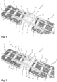
- the first embodiment of a bridging structure 1 according to the invention shown in Fig. 1 serves to support at least one rail 2 of a railroad track 3 in the area of a construction joint 4 in a railroad structure 5.
- This is a railroad structure 5 in which the railroad track 3 has two parallel rails 2, which in turn are fastened to a plurality of sleepers 37 arranged transversely to the rails 2 and which in turn lie in a ballast bed 7.
- the bridging structure 1 has a first truss 8 and a second truss 10.
- the first truss 8 has a long, straight main beam 9 extending across the construction joint and parallel to the longitudinal axis of a rail 2 shown on the left in the figure.
- the main beam of the first truss 8 is arranged laterally on the outer side shown on the left in the figure, next to the first rail 2.
- the second truss 10 also has such a straight main beam 11. However, this is arranged at the side of the first truss 8 and at a distance parallel to it. In other words, it is located on the other longitudinal side of the rail 2, i. e. on the right-hand side in the figure.
- both trusses 8 and 10 are designed in such a way that they can be fastened to parts of the railroad track 3 adjacent to the construction joint 4 and supporting the two rails 2 so that they can be displaced at least partially in the longitudinal direction.
- the two trusses 8 and 10 are namely mounted on two bearing sleepers 6 located to the left of the construction joint 4 and on two bearing sleepers 6 located to the right of the construction joint 4 so as to be at least partially displaceable in the longitudinal direction.
- the truss 8 is mounted on its left side and the truss 10 on its right side in an articulated but non-displaceable manner.
- the other side of the truss 8 or 10 is articulated and longitudinally displaceable, as indicated by the arrows drawn in the figure and pointing in the longitudinal direction of the trusses 8, 10 at the lateral ends of the trusses 8, 10.
- both trusses 8 and 10 are supported on each other in a displaceable manner. They can therefore be displaced relative to each other in the longitudinal direction, as can be seen in comparison with the condition shown in Fig. 2 . This is therefore a statically determined three-point mounting.
- a support beam 12 is arranged on the first truss 8 transverse to its main beam 9 and in its center to support the two rails 2.
- this support beam is aligned transversely to the longitudinal axis of the first truss 8, is rigidly connected to it and is mounted on the second truss 10 so that it can be articulated and moved parallel to the track plane.
- the support beam 12 is designed in such a way that it is arranged in the area of the construction joint 4 and can be guided at least in some areas under the rails 2 to be supported.
- the second truss 10 also has a support beam 13 attached centrally to the main beam 11 for supporting the two rails 2. This is also designed in such a way that it can be passed under the rails 2 to be supported, runs transversely to the longitudinal axis of the second truss 10 and is rigidly connected to the latter. Both trusses 8, 10 thus have a T-shape in plan view.
- the two support beams 12, 13 in turn have a U-shape when viewed in the direction of the track axis.
- Two rail support points 14 are arranged in the central part of the U to support the two rails 2.
- the bearing 15 of the two support beams 12, 13 on the respective other truss 8, 10 is designed as a torsionally soft bearing with respect to the longitudinal track axis. Specifically, this means that the two trusses 8, 10 with their support beams 12, 13 can rotate relative to each other about the longitudinal axis without this leading to significant stresses in the bridging structure 1. In the simplest case, this is achieved with a simple mounting of the support beams 12, 13 from the respective other truss 8, 10, as shown in this example embodiment.
- the support beam 12, 13, which is U-shaped when viewed in the direction of the track axis, has a horizontal retaining plate in the area of the mounting 15, which is attached to the respective upwardly pointing U-leg of the support beam 12, 13 in question.
- the support beam 12, 13 hangs on the respective other truss 8, 10 and, at the same time, longitudinally guided sliding is possible along the elongated main beams 9, 11 of the respective other trusses 8, 10.
- Fig. 1 shows the bridging structure 1 maximally open, i. e. with the maximum width of the construction joint 4 to be bridged.
- the limitation of the opening in the maximum direction is achieved with the aid of stops 16 attached to the trusses 8, 10. These prevent the support beams 12, 13 from sliding too far on the trusses 8, 10 or their main beams 9, 11 and then hitting the edges of the construction joint 4.
- Fig. 2 corresponds to a minimal opening of the bridging structure 1.
- the limitation of the pushing-together movement is effected by an impact of the end faces of the two supporting beams 12, 13 of the trusses 8, 10.
- Both trusses 8, 10 have a truss bearing 17 at each end of the main beams 9, 11 for fastening the trusses 8, 10 to a part of the railroad track 3.
- This fastening can be direct or - as shown here - indirect.
- a cradle carrier 18 is hinged to each truss bearing 17, which in turn is attached to two bearing sleepers 6 in each case.
- the truss bearings 17 can be designed in a fundamentally known manner as a fixed bearing that cannot be displaced or as a bearing that can be displaced in the longitudinal direction, as is also indicated in the figures by the double arrows pointing in the longitudinal direction.
- Each cradle carrier 18 is preferably symmetrically designed in this case.
- the truss bearing 17 is then fastened in the center of the cradle carrier 18, which is otherwise designed as a straight beam. In this way, the vertical forces introduced from the trusses 8, 10 via the cradle carriers 18 into the respective track sections are distributed in half. If the railroad track sections to which the trusses 8, 10 are attached via the cradle carriers 18 are bearing sleepers 6, this extends the time until the ballast bed 7 has to be tamped in this area very noticeably compared to known solutions.
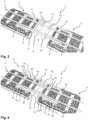
- the second example embodiment of a bridging structure 1 according to the invention shown in Figs. 3 and 4 differs from the first example embodiment only in the type of bearing of the trusses 8, 10. Namely, in this second example embodiment, all four truss bearings 17 are designed as bearings that can be displaced in the longitudinal direction of the trusses 8, 10. As a result, the minimum opening of the bridging structure 1 - as shown in Fig. 4 - can be reduced again compared to the minimum opening of the first example embodiment - as shown in Fig. 2 .
- the first truss 8 again has a long main beam 9 and a support beam 12.
- the support beam 12 is designed to be much wider in some areas than in the previously described example embodiments.
- two rail support points 14 located one behind the other in the direction of the track axis can be accommodated on it for supporting the respective rail 2.
- the support beam 12 thus carries a total of four rail support points 14 for two rails 2.
- the second truss 10 is now much simpler than in the previous examples. It has a straight main beam 11 on which the first truss 8 is suspended with its mounting 15.
- the bearing system of this bridging structure 1 is such that the two truss bearings 17 of the first truss 8 are designed to be longitudinally displaceable and articulated.
- the truss bearing 17 of the second truss 10 which is on the left in the figures, is also designed to be articulated and longitudinally displaceable.
- the bearing 17 lying on the right is an articulated bearing designed to be non-displaceable in the longitudinal direction.
- the second truss 10 is thus supported in a statically determined manner in the longitudinal direction. In conjunction with the stop 16 provided on the second truss 10, this fixed bearing ensures that neither the second truss 10 nor the first truss 8 can slip.
- the entire structure is therefore torsionally soft, statically supported and thus always free of constraints.
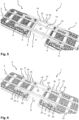
- the embodiment of the bridging structure 1 shown in Fig. 7 corresponds in principle and in its structural design to that of the first embodiment shown in Fig. 1 .
- the bridging structure is here installed in a railroad structure 5 which has a railroad track 3 of the "slab track" type - in this case a railroad track 3 with a concrete slab 19 instead of a ballast bed.
- the rail support points 14 here are attached directly to the concrete slab 19, which may be somewhat thicker in this area and in the form of a cross rib 20. If such cross ribs 20 are present in the concrete slab 19, the cross ribs 20 can be used, analogously to the bearing sleepers 6 shown in Fig.
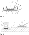
- Fig. 8 now shows the end of the main beam 9 with a longitudinally displaceable truss bearing 17 in an enlarged and longitudinally sectioned view.
- the truss bearing 17 basically consists of a recess in which a pin 21 is located, which is attached to an underlying part (here it is a cradle carrier 18, but it can also be a simple bearing plate, which is attached, for example, to a part of the railroad track 3, e.g. a concrete slab of a slab track) of the bearing 17.
- the truss bearing 17 is to be designed as a sliding bearing, as here, the recess is designed as a longitudinal groove 22 in the truss 8. This allows the pin 21 to slide back and forth in the longitudinal groove 22. So that the pin 21 does not strike hard against the end faces of the recess at maximum or minimum displacement, two spring and/or damping elements 23 are fitted in the example shown here.
- sliding guides 24 made of a low-friction sliding material are still arranged on each side of the longitudinal groove 22.
- the upper side of the pin 21 is of crowned design - as can be seen in Fig. 10 .
- the truss bearing 17 is articulated and can accommodate twisting without generating bending moments or torsional moments in the truss.
- the cradle carrier 18 is attached to two bearing sleepers 6 by two cradle carrier bearings 25.
- the cradle carrier bearings 25 are designed as longitudinally displaceable bearings and similar to a rail support point with low puncture resistance.
- the cradle carrier bearing 25 has a ribbed plate 27 arranged between two elastic intermediate layers 26.
- the cradle carrier 18 is clamped from top to bottom by a clamping plate 28. If very small and thus the resistance to sliding of the cradle carrier 18 in the cradle carrier bearing 25 is low, the cradle carrier 18 can shift relative to the ribbed plate 27 held in the direction of the track axis. In this way, the load introduction into the bearing sleepers 6 is noticeably reduced.
- a large pretensioning force of the clamping plates 28 can generate a resistance to displacement of the cradle carrier in the cradle carrier bearing 25 that is greater than the resistance to displacement of the bearing sleepers in the ballast.
- the cradle carriers are connected to the bearing sleepers in a non-displaceable manner in the direction of the track axis.
- a rail support point 14 which is particularly well suited to the invention, as shown enlarged and sectioned in Fig. 11 , also functions according to this principle. Accordingly, the rail 2 can slide in the direction of the track axis relative to the ribbed plate 29 of the rail support point 14, which has a holding effect due to ribbing transverse to the track axis.
- a sliding plate 30 is arranged under the rail 2 and on an elastic intermediate layer 31, which in turn lies on the ribbed plate 29. Ribbed plate 29 and rail 2 are clamped together by means of clamping screws 32 and tension clamps 33.
- the ribbed plate 29 is in turn braced to a base plate 35 with the interposition of a further elastic intermediate plate 34 by means of clamping screws 32 and tension clamps 33.
- the base plate 35 is ultimately fastened to a bearing sleeper 6 or to a support beam 12, 13, e. g. with screws.
- Elastic fastening of the rail 2 in the direction of the track axis is achieved by a corresponding elasticity of tension clamps 33, elastic intermediate layer 31 and elastic intermediate plate 34.
- the rail support point 14 shown in Fig. 11 is mounted on a bearing sleeper 6.
- the main beam 9 can be seen with the longitudinal groove 22 of the truss bearing 17 and the cradle carrier 18 located below it, together with the cradle carrier bearing 25 shown in detail in Fig. 9 .
- the cradle carrier bearing 25 of the cradle carrier 18 is fixed in a recess 36 at the outer end of the bearing sleeper 6.
Landscapes
- Engineering & Computer Science (AREA)
- Architecture (AREA)
- Civil Engineering (AREA)
- Structural Engineering (AREA)
- Mechanical Engineering (AREA)
- Railway Tracks (AREA)
- Bridges Or Land Bridges (AREA)
Claims (30)
- Überbrückungskonstruktion (1) zur Abstützung wenigstens einer Fahrschiene (2) einer Eisenbahn-Fahrbahn (3) im Bereich einer Bauwerksfuge (4),
dadurch gekennzeichnet, dassdie Überbrückungskonstruktion (1) wenigstens einen länglichen Wiegeträger (1) aufweist, der an der Überbrückungskonstruktion (1) gelenkig angeordnet ist und der zwei Enden mit jeweils einem daran befestigten Wiegeträger-Lager (25) aufweist, mit denen er an der Fahrbahn (3) befestigt werden kannsie eine erste sich im Bereich der Bauwerksfuge (4) im Wesentlichen parallel zur Längsachse der Fahrschiene (2) erstreckende und seitlich neben der Fahrschiene (2) angeordnete, die Bauwerksfuge (4) überbrückenden erste Traverse (8) und eine zur ersten Traverse (8) im Wesentlichen parallel und beabstandet auf der anderen Seite der Fahrschiene (2) angeordnete zweite Traverse (10) aufweist, wobei die Traversen (8, 10) so ausgebildet sind, dass sie an zur Bauwerksfuge (4) benachbarten und die Fahrschiene (2) tragenden Teilen der Eisenbahn-Fahrbahn (3) zumindest teilweise in Längsrichtung verschieblich befestigt werden können, wobei an der ersten Traverse (8) ein erster Stützträger (12) zur Abstützung wenigstens einer Fahrschiene (2) angeordnet ist, der so ausgebildet ist, dass er quer zur Längsachse der ersten Traverse (8) ausgerichtet, mit dieser starr verbunden und an der zweiten Traverse (10) gelenkig und parallel zur Gleisebene verschieblich gelagert ist, und der so gestaltet ist, dass er im Bereich der Bauwerksfuge (4) angeordnet und zumindest bereichsweise unter der wenigstens einen abzustützenden Fahrschiene (2) hindurch geführt werden kann.. - Überbrückungskonstruktion nach Anspruch 1,
dadurch gekennzeichnet, dass
an der Überbrückungskonstruktion (1) wenigstens zwei, vorzugsweise vier, Wiegeträger (18) gelenkig angeordnet sind. - Überbrückungskonstruktion nach Anspruch 1 oder 2,
dadurch gekennzeichnet, dass
wenigstens ein Wiegeträger (18) an einem Ende ein Wiegeträger-Lager (25) aufweist, das eine in Längsrichtung des Wiegeträgers (18) verschiebliche Lagerung an einer zur Lagerung der Übergangskonstruktion herangezogenen Lager-Schwelle (6) und an einem anderen Ende ein Wiegeträger-Lager (25) aufweist, das eine in Längsrichtung feste Lagerung an einer zweiten zur Lagerung herangezogenen Lager-Schwelle (6) ermöglicht. - Überbrückungskonstruktion nach einem der vorhergehenden Ansprüche,
dadurch gekennzeichnet, dass
wenigstens ein Wiegeträger (18) an beiden Enden Wiegeträger-Lager (25) aufweist, die eine in Längsrichtung des Wiegeträgers (18) verschiebliche oder feste Lagerung an den betreffenden Lager-Schwellen (6) ermöglichen. - Überbrückungskonstruktion (1) nach einem der vorhergehenden Ansprüche,
dadurch gekennzeichnet, dass
die Überbrückungskonstruktion (1) eine Vollschiene, eine Beischiene, einen Trägerrost und/oder eine Ausgleichsplatte aufweist. - Überbrückungskonstruktion nach einem der vorhergehenden Ansprüche,
dadurch gekennzeichnet, dass
die Überbrückungskonstruktion (1) einen zweiten Stützträger (13) zur Abstützung wenigstens einer Fahrschiene (2) aufweist, der so ausgebildet ist, dass er quer zur Längsachse der zweiten Traverse (10) ausgerichtet, mit dieser starr verbunden und an der ersten Traverse (8) gelenkig und parallel zur Gleisebene verschieblich gelagert ist und der so gestaltet ist, dass er im Bereich der Bauwerksfuge (4) angeordnet und zumindest bereichsweise unter der wenigstens einen abzustützenden Fahrschiene (2) hindurch geführt werden kann. - Überbrückungskonstruktion nach einem der vorhergehenden Ansprüche,
dadurch gekennzeichnet, dass
wenigstens ein Stützträger (12, 13) als in Richtung der Gleisachse bereichsweise U- oder L-förmiger Balken mit wenigstens einem Schienenstützpunkt (14) ausgebildet ist. - Überbrückungskonstruktion nach einem der vorhergehenden Ansprüche,
dadurch gekennzeichnet, dass
die Lagerung des Stützträgers (12, 13) an der jeweils anderen Traverse (8, 10) als um die Längsachse der Überbrückungskonstruktion (1) torsionsweiche Lagerung ausgeführt ist. - Überbrückungskonstruktion nach einem der vorhergehenden Ansprüche,
dadurch gekennzeichnet, dass
der Stützträger (12, 13) eine Aufhängung (15) aufweist, die so ausgebildet ist, dass der Stützträger (12, 13) an der anderen Traverse (8, 10) so angehängt werden kann, dass er an dieser in deren Längsrichtung entlang gleiten kann. - Überbrückungskonstruktion nach einem der Ansprüche 6 bis 9,
dadurch gekennzeichnet, dass
wenigstens ein Stützträger (12, 13) zumindest bereichsweise plattenartig so breit ausgebildet ist, dass zwei oder mehr Schienenstützpunkte (14) zur Abstützung der jeweiligen Fahrschiene (2) auf ihm angebracht sind. - Überbrückungskonstruktion nach einem der vorhergehenden Ansprüche,
dadurch gekennzeichnet, dass
wenigstens eine Traverse (8, 10) wenigstens einen Anschlag (16) aufweist, der die Verschiebung des auf ihr gelagerten Stützträgers (12, 13) in Längsrichtung der jeweiligen Traverse (8, 10) begrenzt. - Überbrückungskonstruktion nach einem der vorhergehenden Ansprüche,
dadurch gekennzeichnet, dass
wenigstens eine Traverse (8, 10) auf einer Seite der Bauwerksfuge (4) so ausgebildet ist, dass eine in Längsrichtung der Traverse (8, 10) feste Lagerung an einem Teil der Fahrbahn (3) möglich ist. - Überbrückungskonstruktion nach einem der vorhergehenden Ansprüche,
dadurch gekennzeichnet, dass
beide Traversen (8, 10) in Längsrichtung der Traversen (8, 10) so ausgebildet sind, dass sie verschieblich an einem Teil der Fahrbahn (3) gelagert werden können. - Überbrückungskonstruktion nach einem der vorhergehenden Ansprüche,
dadurch gekennzeichnet, dass
wenigstens eine Traverse (8, 10) ein Traversen-Lager (17) zur Befestigung der Überbrückungskonstruktion (1) aufweist. - Überbrückungskonstruktion nach Anspruch 14,
dadurch gekennzeichnet, dass
an wenigstens einem Traversen-Lager (17) ein Wiegeträger (18) gelenkig angeordnet ist. - Überbrückungskonstruktion nach Anspruch 15,
dadurch gekennzeichnet, dass
die verschiebliche Lagerung einer Traverse (8, 10) durch einen an einem Wiegeträger (18) befestigten Lagerzapfen (21) und eine in der jeweiligen Traverse (8, 10) angeordnete Längsnut (22) ausgebildet wird, wobei der Lagerzapfen (21) in der Längsnut (22) der Traverse (8, 10) geführt wird. - Überbrückungskonstruktion nach Anspruch 16,
dadurch gekennzeichnet, dass
in der Längsnut (22) wenigstens eine reibungsreduzierende Gleitplatte (24) angeordnet ist. - Überbrückungskonstruktion nach Anspruch 16 oder 17,
dadurch gekennzeichnet, dass
wenigstens ein Feder- und/oder Dämpfungsmittel (23) an wenigstens einem stirnseitigen Ende einer Längsnut (22) der Traverse (8, 10) angeordnet ist oder sind. - Überbrückungskonstruktion nach Anspruch 12,
dadurch gekennzeichnet, dass
die feste Lagerung einer Traverse (8, 10) durch einen Lagerzapfen (21) und eine Lagerausnehmung (22) in der jeweiligen Traverse so ausgebildet ist, dass die jeweilige Traverse (8, 10) in der Lagerausnehmung (22) auf dem Lagerzapfen (21) in seitlicher Richtung im Wesentlichen unverschieblich aufliegt. - Überbrückungskonstruktion nach einem der vorhergehenden Ansprüche,
dadurch gekennzeichnet, dass
wenigstens ein Schienenstützpunkt (14) vorgesehen ist, der als längsbeweglicher Schienenstützpunkt (14) ausgeführt ist, und der vorzugsweise eine elastische Platte (31, 34) zur Aufnahme von Verschiebungen der wenigstens einen Fahrschiene (2) in deren Längsrichtung aufweist. - Überbrückungskonstruktion nach einem der vorhergehenden Ansprüche,
dadurch gekennzeichnet, dass
die Überbrückungskonstruktion (1) zwischen dem ersten Stützträger (12) und dem zweiten Stützträger (13) wenigstens einen dritten Stützträger aufweist, der wenigstens einen Schienenstützpunkt (14) aufweist, wobei der dritte Stützträger mit der ersten Traverse (8) und mit der zweiten Traverse (10) jeweils gelenkig und längsverschieblich verbunden ist. - Überbrückungskonstruktion nach einem der vorhergehenden Ansprüche,
dadurch gekennzeichnet, dass
die Überbrückungskonstruktion (1) eine Steuervorrichtung zum Einstellen von gleichmäßigen, insbesondere möglichst kleinen, Abständen zwischen den einzelnen Stützträgern (12, 13) der wenigstens einen Fahrschiene (2) aufweist. - Überbrückungskonstruktion nach einem der vorhergehenden Ansprüche,
dadurch gekennzeichnet, dass
zwischen den wenigstens zwei benachbarten Stützträgern (12, 13) und/oder zwischen wenigstens einem Stützträgern (12,13) und wenigstens einem benachbarten Rand der Bauwerksfuge (4) wenigstens ein nachgiebiges und/oder bewegliches Dichtungselement angebracht ist. - Eisenbahnbauwerk (5) welches eine Bauwerksfuge (4) und eine Fahrbahn (3) aufweist, welche wenigstens eine Fahrschiene (2) aufweist, die über die Bauwerksfuge (4) geführt wird, die sich zwischen zwei die Fahrbahn (3) tragenden Bauwerksteilen des Eisenbahnbauwerks (5) erstreckt,
dadurch gekennzeichnet, dass
die wenigstens eine Fahrschiene (2) im Bereich der Bauwerksfuge (4) durch eine Überbrückungskonstruktion (1) nach einem der vorhergehenden Ansprüche abgestützt wird. - Eisenbahnbauwerk nach Anspruch 24,
dadurch gekennzeichnet, dass
das Eisenbahnbauwerk (5) eine Eisenbahnbrücke aufweist. - Eisenbahnbauwerk nach Anspruch 24 oder 25,
dadurch gekennzeichnet, dass
die Überbrückungskonstruktion (1) schwimmend an der Fahrbahn (3) befestigt ist. - Eisenbahnbauwerk nach einem der Ansprüche 24 bis 26,
dadurch gekennzeichnet, dass
die Fahrbahn (3) als Feste Fahrbahn mit einer Betonplatte (19) ausgeführt ist und die Überbrückungskonstruktion (1) an der Betonplatte (19) befestigt ist. - Eisenbahnbauwerk nach einem der Ansprüche 24 bis 26,
dadurch gekennzeichnet, dass
die Fahrbahn (3) als Fahrbahn mit Schotterbett (7) und Schwellen (37) ausgeführt ist und die Überbrückungskonstruktion (1) an wenigstens zwei, vorzugsweise vier, Lager-Schwellen (6) der Fahrbahn (3) befestigt ist. - Eisenbahnbauwerk nach einem der Ansprüche 24 bis 26 oder 28,
dadurch gekennzeichnet, dass
die Lager-Schwellen (6) an denen die Überbrückungskonstruktion (1) befestigt ist an ihren äußeren Enden jeweils eine Ausnehmung (36) zur Aufnahme eines Teils der Überbrückungskonstruktion, insbesondere eines Wiegeträger-Lagers (25), aufweisen. - Eisenbahnbauwerk nach einem der Ansprüche 24 bis 26, 28 oder 29,
dadurch gekennzeichnet, dass
die zur Auflagerung der Überbrückungskonstruktion (1) herangezogenen Lager-Schwellen (6) mittels Abstandshaltern, insbesondere entsprechend dimensionierten Stangen, mit weiteren benachbarten Schwellen (37) in Längsrichtung der Fahrschiene (2) lastabtragend verbunden werden.
Applications Claiming Priority (2)
| Application Number | Priority Date | Filing Date | Title |
|---|---|---|---|
| DE102021205982.1A DE102021205982A1 (de) | 2021-06-11 | 2021-06-11 | Überbrückungskonstruktion zur Abstützung wenigstens einer Fahrschiene einer Eisenbahn-Fahrbahn im Bereich einer Bauwerksfuge und Eisenbahnbauwerk mit einer solchen Überbrückungskonstruktion |
| PCT/EP2022/065801 WO2022258798A1 (en) | 2021-06-11 | 2022-06-10 | Bridging structure for supporting at least one rail of a railroad track in the area of a construction joint and railroad structure with such a bridging structure |
Publications (3)
| Publication Number | Publication Date |
|---|---|
| EP4352303A1 EP4352303A1 (de) | 2024-04-17 |
| EP4352303B1 true EP4352303B1 (de) | 2025-04-23 |
| EP4352303C0 EP4352303C0 (de) | 2025-04-23 |
Family
ID=82156523
Family Applications (1)
| Application Number | Title | Priority Date | Filing Date |
|---|---|---|---|
| EP22732527.1A Active EP4352303B1 (de) | 2021-06-11 | 2022-06-10 | Überbrückungskonstruktion zur abstützung mindestens einer schiene eines gleises im bereich einer bauwerksfuge sowie eisenbahnbauwerk mit einer solchen überbrückungskonstruktion |
Country Status (9)
| Country | Link |
|---|---|
| EP (1) | EP4352303B1 (de) |
| KR (1) | KR20240019355A (de) |
| CN (1) | CN117529589A (de) |
| CO (1) | CO2023018588A2 (de) |
| DE (1) | DE102021205982A1 (de) |
| ES (1) | ES3035394T3 (de) |
| MX (1) | MX2023014472A (de) |
| PL (1) | PL4352303T3 (de) |
| WO (1) | WO2022258798A1 (de) |
Families Citing this family (1)
| Publication number | Priority date | Publication date | Assignee | Title |
|---|---|---|---|---|
| PL447071A1 (pl) * | 2023-12-12 | 2025-06-16 | Politechnika Warszawska | Tor kolejowy o zwiększonej odporności na rozszerzalność cieplną szyn |
Family Cites Families (9)
| Publication number | Priority date | Publication date | Assignee | Title |
|---|---|---|---|---|
| DE1963457U (de) | 1967-02-04 | 1967-07-06 | Johannes Doernen Stahlbauwerk | Abdeckvorrichtung fuer dehnungsfugen von bruecken od. dgl. |
| DE19806566C5 (de) | 1998-02-17 | 2007-04-05 | Stog, Arnulf | Ausgleichplatte für Eisenbahnbrücken |
| DE19861397B4 (de) * | 1998-02-17 | 2012-03-01 | Arnulf Stog | Ausgleichskonstruktion |
| DE10030448B4 (de) * | 2000-06-21 | 2005-04-21 | Stog, Arnulf | Übergangskonstruktion für Gleise von Eisenbahnbrücken |
| DE10033553A1 (de) | 2000-07-11 | 2002-01-24 | Butzbacher Weichenbau Gmbh | Unterstützung für Schienen |
| AT8456U1 (de) * | 2005-02-09 | 2006-08-15 | Gmundner Fertigteile Gmbh | Schienengleicher bahnübergang |
| DE102013205573A1 (de) * | 2013-03-28 | 2014-10-02 | Maurer Söhne Engineering GmbH & Co. KG | Übergangskonstruktion und Eisenbahnbrücke mit einer solchen Übergangskonstruktion |
| CN203229869U (zh) * | 2013-04-27 | 2013-10-09 | 中铁二院工程集团有限责任公司 | 铁路无砟轨道桥梁钢桁梁与混凝土简支梁交界位置梁端构造 |
| CN108517761B (zh) * | 2018-05-25 | 2024-01-12 | 中国铁道科学研究院集团有限公司铁道建筑研究所 | 一种适用于超大跨度铁路钢桥的整体式梁端伸缩装置 |
-
2021
- 2021-06-11 DE DE102021205982.1A patent/DE102021205982A1/de active Pending
-
2022
- 2022-06-10 MX MX2023014472A patent/MX2023014472A/es unknown
- 2022-06-10 EP EP22732527.1A patent/EP4352303B1/de active Active
- 2022-06-10 PL PL22732527.1T patent/PL4352303T3/pl unknown
- 2022-06-10 ES ES22732527T patent/ES3035394T3/es active Active
- 2022-06-10 CN CN202280041718.8A patent/CN117529589A/zh active Pending
- 2022-06-10 WO PCT/EP2022/065801 patent/WO2022258798A1/en not_active Ceased
- 2022-06-10 KR KR1020247001127A patent/KR20240019355A/ko active Pending
-
2023
- 2023-12-28 CO CONC2023/0018588A patent/CO2023018588A2/es unknown
Also Published As
| Publication number | Publication date |
|---|---|
| CO2023018588A2 (es) | 2024-01-25 |
| ES3035394T3 (en) | 2025-09-02 |
| PL4352303T3 (pl) | 2025-08-11 |
| EP4352303A1 (de) | 2024-04-17 |
| KR20240019355A (ko) | 2024-02-14 |
| CN117529589A (zh) | 2024-02-06 |
| DE102021205982A1 (de) | 2022-12-15 |
| MX2023014472A (es) | 2024-01-17 |
| WO2022258798A1 (en) | 2022-12-15 |
| EP4352303C0 (de) | 2025-04-23 |
Similar Documents
| Publication | Publication Date | Title |
|---|---|---|
| CN103469726B (zh) | 一种大位移铁路桥梁梁端伸缩装置 | |
| KR102279940B1 (ko) | 접속 영역용 레일 체결 장치 | |
| US20100065651A1 (en) | Solid track comprising a concrete strip | |
| Kaewunruen | Acoustic and dynamic characteristics of a complex urban turnout using fibre-reinforced foamed urethane (FFU) bearers | |
| DK2978897T3 (en) | Transition construction and railway bridge with such a transitional construction | |
| EP4352303B1 (de) | Überbrückungskonstruktion zur abstützung mindestens einer schiene eines gleises im bereich einer bauwerksfuge sowie eisenbahnbauwerk mit einer solchen überbrückungskonstruktion | |
| KR101399839B1 (ko) | 철도교량 단부 횡단 궤도 구조 및 그 시공 방법 | |
| DE19806566C5 (de) | Ausgleichplatte für Eisenbahnbrücken | |
| US20050166786A1 (en) | Method for precisely placing a guideway support, and guideway | |
| KR100655861B1 (ko) | 철도교량용 침목 체결시스템 | |
| KR101225807B1 (ko) | 교량 위의 철도 차량용 고정 트랙 | |
| KR20180086961A (ko) | 슬라이드층을 이용한 종방향 변위 분리에 의한 교량 상호작용 저감형 슬라이딩 콘크리트 궤도 및 이러한 슬라이딩 콘크리트 궤도가 부설된 철도 교량 | |
| KR102003695B1 (ko) | 철도교량용 궤도상판조립체 | |
| US6581848B1 (en) | Sleeper frame for a rail system for rail-mounted vehicles, especially for a ballasted track | |
| Hess | Rail expansion joints–the underestimated track work material? | |
| RU2328569C1 (ru) | Железнодорожный путь для тоннелей | |
| RU112203U1 (ru) | Устройство верхнего строения пути | |
| CN110700017A (zh) | 一种下承式连续支承轨道系统的施工方法 | |
| RU2817708C1 (ru) | Верхнее строение железнодорожного пути с непрерывным опиранием рельсов | |
| Matsumoto et al. | Some experiences on track-bridge interaction in Japan | |
| RU2415987C2 (ru) | Железнодорожный путь для мостов и тоннелей | |
| CN101139818B (zh) | 桥梁轨道纵向隔离装置 | |
| JP2014163150A (ja) | 下路桁 | |
| RU2765269C1 (ru) | Железнодорожный лежневый путь | |
| CN119711264B (zh) | 一种含钢护板的梁式无砟轨道 |
Legal Events
| Date | Code | Title | Description |
|---|---|---|---|
| STAA | Information on the status of an ep patent application or granted ep patent |
Free format text: STATUS: UNKNOWN |
|
| STAA | Information on the status of an ep patent application or granted ep patent |
Free format text: STATUS: THE INTERNATIONAL PUBLICATION HAS BEEN MADE |
|
| PUAI | Public reference made under article 153(3) epc to a published international application that has entered the european phase |
Free format text: ORIGINAL CODE: 0009012 |
|
| STAA | Information on the status of an ep patent application or granted ep patent |
Free format text: STATUS: REQUEST FOR EXAMINATION WAS MADE |
|
| 17P | Request for examination filed |
Effective date: 20240110 |
|
| AK | Designated contracting states |
Kind code of ref document: A1 Designated state(s): AL AT BE BG CH CY CZ DE DK EE ES FI FR GB GR HR HU IE IS IT LI LT LU LV MC MK MT NL NO PL PT RO RS SE SI SK SM TR |
|
| DAV | Request for validation of the european patent (deleted) | ||
| DAX | Request for extension of the european patent (deleted) | ||
| GRAP | Despatch of communication of intention to grant a patent |
Free format text: ORIGINAL CODE: EPIDOSNIGR1 |
|
| STAA | Information on the status of an ep patent application or granted ep patent |
Free format text: STATUS: GRANT OF PATENT IS INTENDED |
|
| INTG | Intention to grant announced |
Effective date: 20241213 |
|
| GRAS | Grant fee paid |
Free format text: ORIGINAL CODE: EPIDOSNIGR3 |
|
| GRAA | (expected) grant |
Free format text: ORIGINAL CODE: 0009210 |
|
| STAA | Information on the status of an ep patent application or granted ep patent |
Free format text: STATUS: THE PATENT HAS BEEN GRANTED |
|
| AK | Designated contracting states |
Kind code of ref document: B1 Designated state(s): AL AT BE BG CH CY CZ DE DK EE ES FI FR GB GR HR HU IE IS IT LI LT LU LV MC MK MT NL NO PL PT RO RS SE SI SK SM TR |
|
| REG | Reference to a national code |
Ref country code: GB Ref legal event code: FG4D |
|
| REG | Reference to a national code |
Ref country code: CH Ref legal event code: EP |
|
| REG | Reference to a national code |
Ref country code: DE Ref legal event code: R096 Ref document number: 602022013617 Country of ref document: DE |
|
| REG | Reference to a national code |
Ref country code: IE Ref legal event code: FG4D |
|
| U01 | Request for unitary effect filed |
Effective date: 20250520 |
|
| U07 | Unitary effect registered |
Designated state(s): AT BE BG DE DK EE FI FR IT LT LU LV MT NL PT RO SE SI Effective date: 20250526 |
|
| U20 | Renewal fee for the european patent with unitary effect paid |
Year of fee payment: 4 Effective date: 20250715 |
|
| REG | Reference to a national code |
Ref country code: GR Ref legal event code: EP Ref document number: 20250401365 Country of ref document: GR Effective date: 20250808 |
|
| REG | Reference to a national code |
Ref country code: ES Ref legal event code: FG2A Ref document number: 3035394 Country of ref document: ES Kind code of ref document: T3 Effective date: 20250902 |
|
| PGFP | Annual fee paid to national office [announced via postgrant information from national office to epo] |
Ref country code: ES Payment date: 20250718 Year of fee payment: 4 |
|
| PGFP | Annual fee paid to national office [announced via postgrant information from national office to epo] |
Ref country code: NO Payment date: 20250702 Year of fee payment: 4 Ref country code: GR Payment date: 20250708 Year of fee payment: 4 |
|
| PGFP | Annual fee paid to national office [announced via postgrant information from national office to epo] |
Ref country code: TR Payment date: 20250718 Year of fee payment: 4 Ref country code: PL Payment date: 20250611 Year of fee payment: 4 |
|
| PG25 | Lapsed in a contracting state [announced via postgrant information from national office to epo] |
Ref country code: HR Free format text: LAPSE BECAUSE OF FAILURE TO SUBMIT A TRANSLATION OF THE DESCRIPTION OR TO PAY THE FEE WITHIN THE PRESCRIBED TIME-LIMIT Effective date: 20250423 |
|
| PGFP | Annual fee paid to national office [announced via postgrant information from national office to epo] |
Ref country code: CH Payment date: 20250701 Year of fee payment: 4 |
|
| PG25 | Lapsed in a contracting state [announced via postgrant information from national office to epo] |
Ref country code: RS Free format text: LAPSE BECAUSE OF FAILURE TO SUBMIT A TRANSLATION OF THE DESCRIPTION OR TO PAY THE FEE WITHIN THE PRESCRIBED TIME-LIMIT Effective date: 20250723 |
|
| PG25 | Lapsed in a contracting state [announced via postgrant information from national office to epo] |
Ref country code: IS Free format text: LAPSE BECAUSE OF FAILURE TO SUBMIT A TRANSLATION OF THE DESCRIPTION OR TO PAY THE FEE WITHIN THE PRESCRIBED TIME-LIMIT Effective date: 20250823 |
|
| PG25 | Lapsed in a contracting state [announced via postgrant information from national office to epo] |
Ref country code: SM Free format text: LAPSE BECAUSE OF FAILURE TO SUBMIT A TRANSLATION OF THE DESCRIPTION OR TO PAY THE FEE WITHIN THE PRESCRIBED TIME-LIMIT Effective date: 20250423 |
|
| PG25 | Lapsed in a contracting state [announced via postgrant information from national office to epo] |
Ref country code: CZ Free format text: LAPSE BECAUSE OF FAILURE TO SUBMIT A TRANSLATION OF THE DESCRIPTION OR TO PAY THE FEE WITHIN THE PRESCRIBED TIME-LIMIT Effective date: 20250423 |
|
| PG25 | Lapsed in a contracting state [announced via postgrant information from national office to epo] |
Ref country code: SK Free format text: LAPSE BECAUSE OF FAILURE TO SUBMIT A TRANSLATION OF THE DESCRIPTION OR TO PAY THE FEE WITHIN THE PRESCRIBED TIME-LIMIT Effective date: 20250423 |
|
| PG25 | Lapsed in a contracting state [announced via postgrant information from national office to epo] |
Ref country code: MC Free format text: LAPSE BECAUSE OF FAILURE TO SUBMIT A TRANSLATION OF THE DESCRIPTION OR TO PAY THE FEE WITHIN THE PRESCRIBED TIME-LIMIT Effective date: 20250423 |
|
| PLBE | No opposition filed within time limit |
Free format text: ORIGINAL CODE: 0009261 |
|
| STAA | Information on the status of an ep patent application or granted ep patent |
Free format text: STATUS: NO OPPOSITION FILED WITHIN TIME LIMIT |
|
| REG | Reference to a national code |
Ref country code: CH Ref legal event code: L10 Free format text: ST27 STATUS EVENT CODE: U-0-0-L10-L00 (AS PROVIDED BY THE NATIONAL OFFICE) Effective date: 20260304 |